

Window Master WSC 204, WSC 204KP, WSC 204MH, WSC 204BZ Operating Manual/technical Information
DK
+45 4567 0300
info.dk@windowmaster.com
UK & IE
+44 (0) 1536 510990
info@windowmaster.co.uk
DE
+49 (0) 5221 6940 -500 Vertrieb / -650 Technik
info@windowmaster.de
CH
+41 (0) 62 289 22 22
info@windowmaster.ch
www.windowmaster.com
Other markets
+45 4567 0300
info@windowmaster.com
WSC 204 0102 / WSC 204MH 0102 / WSC 204BZ 0102 / WSC 204KP 0102 install 1606-UK ©WindowMaster 2011, 2016 ®WindowMaster is a registered trademark used under licence by WindowMaster Group
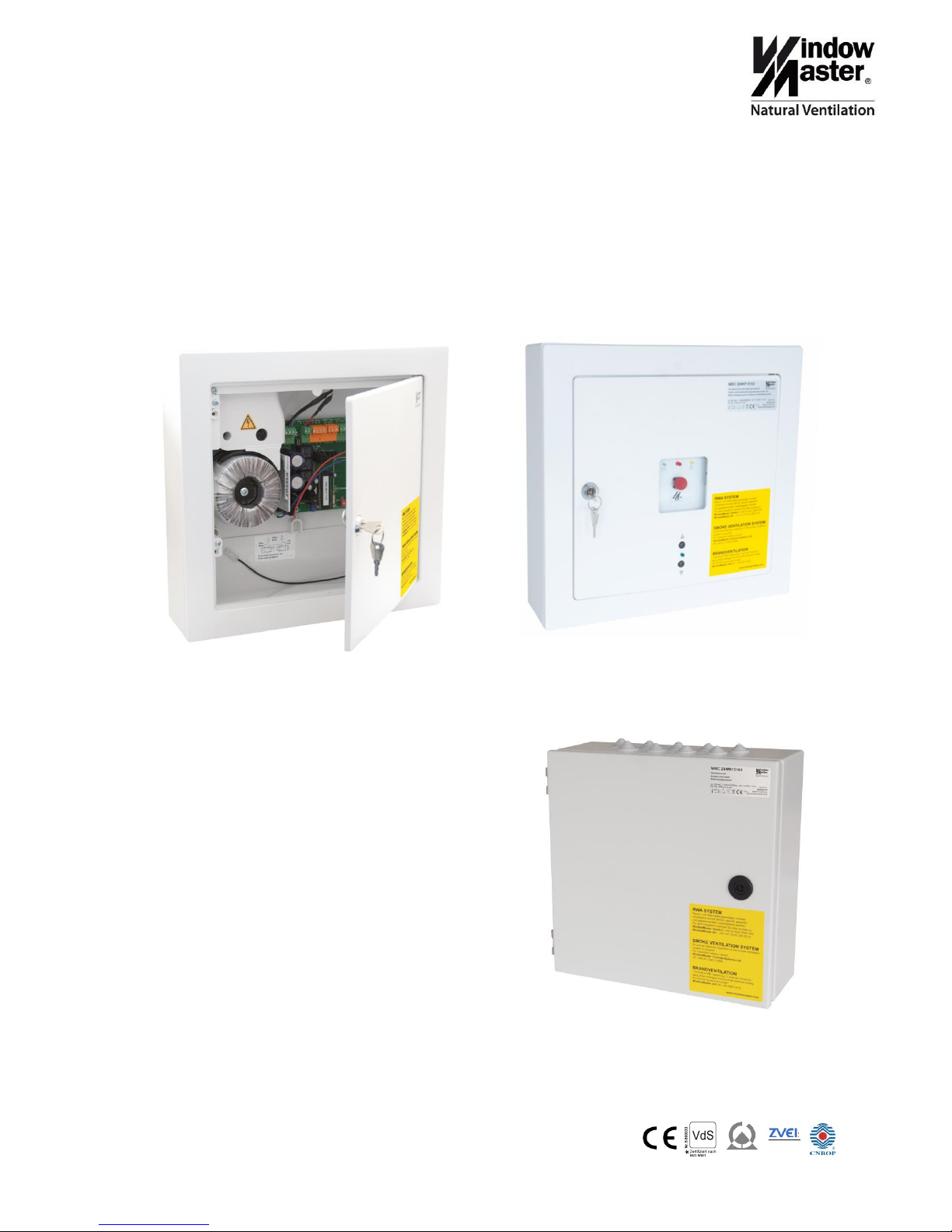
WSC 204
(WSC 204 0102 / WSC 204MH 0102 / WSC 204KP 0102 / WSC 204BZ 0102)
Smoke control panel
Operating manual / Technical information
WSC 204 0102 – WSC 204BZ 0102
plastic housing
WSC 204KP 0102
plastic housing with integrated break glass unit
WSC 204MH 0102 steel housing
Mitglied im
Fach krei s
elek trom otori sc h
betri eben e
Rauch - und Wärm e-
abz ugs anla gen

2
Table of contents
1. Safety information .......................................................................................................................................... 3
2. Technical description ..................................................................................................................................... 4
2.1. Accessories ........................................................................................................................................... 5
3. Operating elements and fuse review ............................................................................................................. 6
4. Function description....................................................................................................................................... 7
4.1. Smoke and heat extraction .................................................................................................................... 7
4.2. Ventilation functions............................................................................................................................... 8
4.3. General information ............................................................................................................................... 9
4.4. Connection possibilities ......................................................................................................................... 9
4.5. Optional plug-in modules ..................................................................................................................... 10
4.6. Back-up batteries charge ..................................................................................................................... 10
4.7. Operation/ Setting possibilities ............................................................................................................ 10
5. Installation .................................................................................................................................................... 11
5.1. Surface mounting ................................................................................................................................. 11
5.2. Countersunk mounting ........................................................................................................................ 12
5.3. Cable routing ....................................................................................................................................... 12
5.4. Installation ............................................................................................................................................ 12
5.5. Installation of the Break glass unit, ventilation keypad and detector ................................................... 13
6. Cable dimensioning ..................................................................................................................................... 13
6.1. Cable length table ................................................................................................................................ 13
7. Cable plan .................................................................................................................................................... 14
8. Wiring diagram ............................................................................................................................................. 15
8.1. Standard wiring diagram ...................................................................................................................... 15
8.2. Wiring diagram WSC 204KP ............................................................................................................... 16
8.3. Various wiring diagrams ...................................................................................................................... 17
9. Commisioning and troubleshooting ............................................................................................................. 18
10. Maintenance ............................................................................................................................................ 20

3
1. Safety information
Attention!
Adherence to the following information is mandatory:
Only allow correspondingly trained, qualified and skilled personnel to carry out installation work.
Reliable operation and the avoidance of damage and hazards is only guaranteed if installation and settings are
carried out carefully in accordance with these instructions.
Hazards to persons ensuing from flaps and wings operated by electric motors.
The forces occurring in the automatic mode can be such that parts of the body could get crushed.
When opened, actuators could protrude into the room. For this reason, measures have to be taken prior to
starting up the actuators, which exclude the danger of injury.
With wings tilting inwards or outwards, the wing must be protected from hinging down once the actuator is
unhooked (e.g. for window cleaning).
For safety reasons we recommend the use of catching shears.
In the event that wings and flaps are subjected to rain or high wind loads, we recommend to connect a rain
and/or wind detector to the smoke control panel, which will automatically close the flaps when comfort
ventilation.
The house can be mounted either as counter sunk or surface.
The manufacturer does not assume any liability for possible damage resulting from inappropriate use.
230V AC dangerous voltage
Can cause death, severe injury or considerable damage to assets.
The connection of the control system is reserved for qualified personnel.
Disconnect all poles of the unit from the supply voltage prior to opening, installation or assembling. Adhere to
national regulations.
Field of application
The central control system is exclusively designed for the automatic closing of smoke extraction systems,
windows, flaps or doors.
Always check that your system meets the valid regulations.
Pay particular attention to the opening cross section, the opening time and opening speed. The cable cross
sections depend on the cable length and current consumption (amperage).
Maintenance work
See last page in this instruction.
Cable routing and electrical connection
Fuse the 230V AC power supply cable separately on site.
Leave the insulation of the power supply cable in place up to the mains terminal.
Adhere to the DIN and VDE regulations (Germany) or equivalent in your country.
Establish the cable types, if necessary, with the local approval bodies or the fire protection authority.
Do not conceal flexible cables. Junction box must be accessible for maintenance purposes.
Disconnect all poles of the mains voltage and the accumulators prior to starting maintenance work or making
changes to the system.
Secure the system to prevent unintentional switching on again.
Design cable types, lengths and cross sections in accordance with the technical information.
Route all low voltage cables (24V DC) separate from the power current cables.

4
2. Technical description
Function
WSC 204 / WSC 204KP / WSC 204MH
Opens the window actuators when triggered by a SHE-signal caused by smoke
detector or break glass unit.
WSC 204BZ
Closes the window actuators when triggered by a SHE-signal caused by smoke
detector and opens the actuators when activating a break glass unit.
Supply voltage
230V AC / 50/60Hz ((±10%))
Safety transformer
according EN 61558
Power consumption
max. 150VA
Actuator secondary voltage
rated voltage 24V
open circuit voltage at 230 VAC typ. 28V DC
open circuit voltage at 253VAC max 31.3V DC
actuator voltage at 230 VAC / 4.8A load typ. 22V DC
ripple at full load (4.8A) max. 6% (= 3.8Vpp)
open circuit voltage at battery operation min 18.7V DC
Inrush current
Max 6A<5msec
Standby consumption
4W
Switch time between 230V- and
battery operation
max 2.5sec
Emergency power supply
batteries
2 x 12V / 3,4Ah. Expected lifetime 4 years. (2pcs. WSA 003). Only use genuine
WindowMaster back up batteries.
Charging unit:
Charging voltage: 27,7 – 27,8 at 20ºC
Charging current: 350mA, current limited
Operating duration (emergency
power supply )
72 hours if batteries are fully charged (1,9Ah)
Current load of the actuators
(battery and 230V operation)
max. 4,8A
Current load of the smoke unit
(batteries, surveillance, periphery)
max. 0,7A
Switch-on duration
40% ED
Reopening the actuators
during the first 30 min. after a SHE-trig the actuators cyclically every 2 min.
Review of fuses
mains 1A slow-blow
actuator fuse 5A slow-blow
battery 630mA medium slow-blow
Type of connection to external
mains screw terminal / plug-screw terminals / 0.5-2.5mm²
Cable monitoring
automatic detectors (detector circuit with active end module), break glass unit
(detector circuit with end resistor), actuators (with motor end module), batteries
(cyclic measurement)
Message OK, fault and alarm
optically alternating or steady signals by LED's:
steady green LED = operating
alternating yellow LED = malfunction of battery(at battery voltage less than 19V
or above 29V), actuator, break glass unit or smoke
steady red LED = alarm (short circuit)
Automatic smoke triggering
Smoke triggering when temperature inside the compact unit exceeds 72°C
Operating conditions
-5°C - 40°C, max. 90% relative humidity (not condensing)
Approval / Certification
WSC 204 / WSC 204KP / WSC 204BZ: approved according to EN12101-10
Protection type
WSC 204 / WSC 204KP / WSC 204BZ
IP 30 (plastic housing)
WSC 204MH
IP54 (steel housing)

5
Housing
WSC 204 / WSC 204KP / WSC 204BZ
Plastic house for flush.
Delivered with a plastic frame for surface mounting.
Protection class I
Dimensions (WxHxD) 368x353x97/95mm
Cut-out hole (WxHxD) 325±5 x 311±5 x min.80mm.
WSC 204MH
Steel housing for surface mounting.
300 x 300 x 120mm.
Delivery includes
Smoke control panel with 2 x 3,4Ah back-up batteries (2 x WSA 003).
Note
We reserve the rights to make changes
2.1. Accessories
Alarm and fault module (master slave)
WSA 301
Linking of wind/rain signal module
WSA 302
Timer ventilation module
WSA 303
Gap ventilation module
WSA 304B
ASV Module
WSA 306
Motor end module
WSA 432
Smoke detector end module
WSA 433
Replacement PCB without transformer for WSC 204 & WSC 204BZ
WSA 321 0102
Replacement PCB without transformer for WSC 204KP
WSA 327 0101
Transformer
WSA 328 0101
Locking cylinder with 2 keys for WSC 204, WSC 204BZ & WSC 204KP
WSA 440
Spare key for WSC 204, WSC 204BZ & WSC 204KP
WSA 441
Spare key for WSC 204MH
WSA 439
6
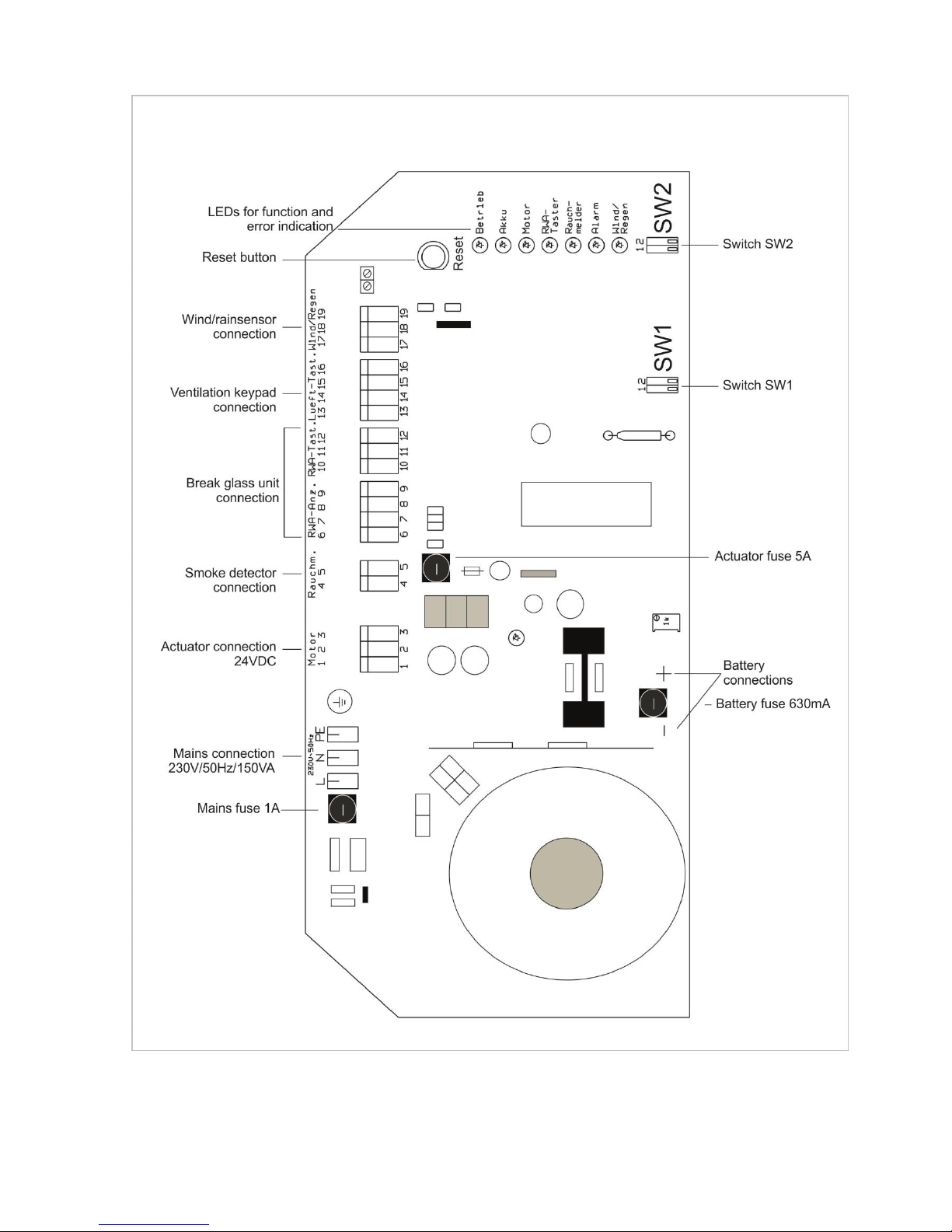
3. Operating elements and fuse review
 Loading...