

Page 1

www.WindowMaster.com
WindowMaster A/S Skelstedet 13 2950 Vedbæk
Danmark
Tel.: +45 4567 0300 Fax: +45 4567 0390
WindowMaster GmbH Zum Bache 4 32549 Bad Oeynhausen
Deutschland
Tel.: +49 (0) 5731-7583-0 Fax: +49 (0) 5731-7583-79
WindowMaster Control Systems Ltd. UNIT 21 Port Tunnel Business Park Dublin 17
Ireland
Tel: +353 (0) 1894 1444 Fax: +44 (0) 1536 526321
WindowMaster AG Industriestrasse 7 4632 Trimbach
Schweiz
Tel.: +41 (0) 62 289 22 22 Fax: +41 (0) 62 289 22 20
WindowMaster Control Systems Ltd. Kettering Parkway Wellingborough Road Kettering Northants NN15 6XR
United Kingdom
Tel.: +44 (0) 1536 510990 Fax: +44 (0) 1536 526321
WEA 102 install 0510-UK ©WindowMaster 2009,2010 ®WindowMaster is a registered trademark used under license by WindowMaster Group 1
WEA 102
KNX - Power supply
Installation instruction: Please read the manual carefully before installment. The manual should be kept.
Table of content:
1. Technical data
2. Declaration of conformity
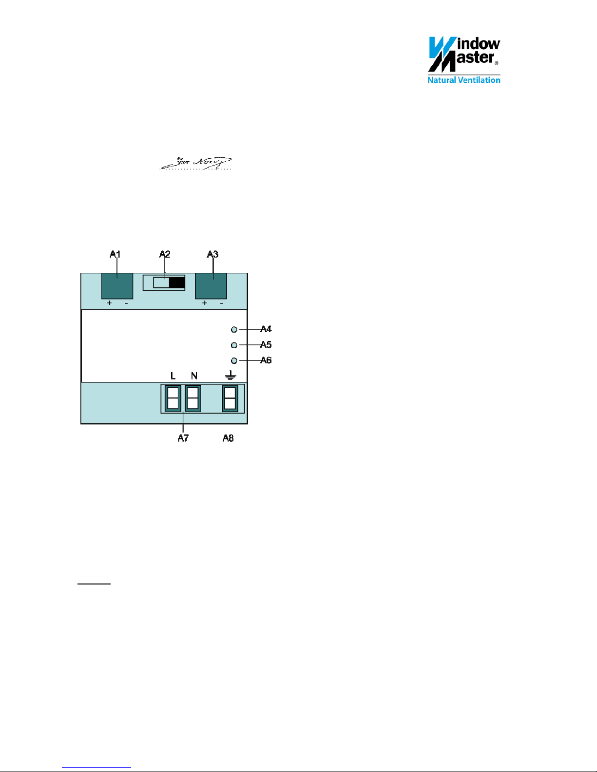
3. Placement and functions of LEDs and switches
4. Mounting and connection
1.Technical data
Size
4 DIN-rail modules of 18mm
Input voltage
120-230 VAC, 50 / 60Hz, allowed range 102-253 VAC
Power consumption
approx 24VA (nominal)
Output voltage
29 VDC (nominal value), allowed range 28-30 VDC, low current (SELV)
Output current
640 mA (nominal value), short circuit current limited to 1,5 A
Buffer time
by power failure of the engagement voltage approx 200ms by nominal load
Connection
Input (net)
plug-in terminals
- 0,5…3,3mm² (AWG 12) onewired, stripping length 9-10mm
Output (bus)
spring contact on data rail
bus terminal (black-red), plug-in terminals, 0,6…0,8mm² onewired
Output voltage
(unthrottlet)
bus terminal (yellow-white), plug-in terminals, 0,6…0,8mm² onewired
Protection type
IP 20
EMC-requirements
EN 50090-2-2
Surrounding
conditions
Working Working temperature -5 - +45°C
Rel. humidity 5% - 93% (non condensation)
Storage Storage temperature -25 - +70°C
rel. Humidity 5% - 93% (non condensation)
Page 2
WEA 102 install 0510-UK ©WindowMaster 2009,2010 ®WindowMaster is a registered trademark used under license by WindowMaster Group
2. Declaration of conformity
We hereby confirm that power supply WEA 102 complies with
- EMC directive 89/336/EEC, as amended (91/263/EEC, 92/31/EEC, 93/68/EEC)
- Low Voltage Directive 73/23/EEC as amended (93/68/EEC) and
- EIB Handbook version 3 Volume 4 Part 2 (Electrical Safety, EMC, environmental conditions) and
Volume 9 part 1/Part 2/del 3 (Electrical and mechanical features standardized EIB).
WindowMaster A/S: . . . . . . . . . . . . . . . . . . . . . . . . . . . . . . . . . . . . . . . . . . . . . .
(Jan Norup, Manager Product Solutions)
Skelstedet 13, DK-2950 Vedbæk, 25. May 2010 Declaration no. 029 0510 CE
3. Placement and functions of LEDs- and switches
Picture 2
A1 Bus terminal red-black (low current terminal)
A2 Reset-contact
A3 Bus terminal yellow-white (low current terminal)
A4 Red LED – indicates that the WEA 102 is positioned in reset mode
A5 Green LED – indicates that the WEA 102 is working correct
A6 Red LED – indicates that the bus line is overloaded or short circuited
A7 Plug-in terminals for connection supply voltage (net terminal)
A8 Earth terminal
Installation conditions
The instrument can be used for permanent installations indoor in dry rooms for built-in distribution board or cabinets with
DIN-rail.
Warning
The product must be built-in to a powercurrent distribution board (230/400).
The product must be installed and started by an authorized electrician.
For safety reasons it must be possible to disconnect the WEA 102.
The existing safety precautions must be kept.
The product must not be opened.
The planning and working on electric systems must respect all relevant national guidelines, directions and regulations.
2
Page 3
WEA 102 install 0510-UK ©WindowMaster 2009,2010 ®WindowMaster is a registered trademark used under license by WindowMaster Group
4. Mounting and connecting
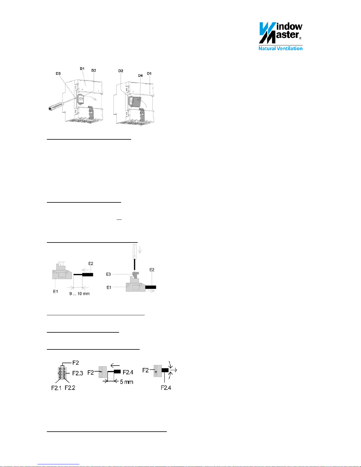
Picture 3
Connection to Bus without DIN-rain
If the connection to the Bus terminals is established without the use of a DIN-rail, the screening cap on the data rail
connection must be removed and replaced with the enclosed isolation cap, to ensure sufficient isolation from the DIN-rail.
Removal of cap: (picture 3)
On the back side of the power supply (D1) a cap (D3) is covering the connection contact (D2).
Insert a screwdriver between the power supply (D1) and the cap (D3) and remove the cap.
Mounting of isolation cap: (picuture 3)
Place the isolation cap (D4) on top of the contact system and press it down until it clicks.
Connection to bus with DIN-rail
WEA 102 is clicked onto the DIN-rail.
Ensure that the type shields on all
the products placed on the DIN-rail are turning in the same direction (reading
direction), this will ensure that the polarization of the products are correct.
Free areas on the DIN-rail must be shielded / covered.
Connection of main voltage (picture 4)
Picture 4
Connection is carried out with the plug-in terminals (E1).
The wire (E2) is stripped ca. 9-10mm.
Disconnection of main voltage (picture 4)
With a screwdriver, press on the lock (E3) on the terminal and pull out the wire (E2) of the terminal (E1).
Installation of the bus terminal
Place the terminal in the guiding groove and press the terminal down to the stop.
Connection of bus terminals (picture 5)
Picture 5
- For terminal (F2) a 0,6…0,8mm² onewired conductor is used.
- Terminal F2 consists of a red (yellow) terminal (F2.1) and a black (white) terminal F2.2.
- Each terminal can be connected to up to 4 onewired of 0,6…0,8mm².
- Conductor F2.4 is stripped approx 5mm and inserted into terminal F2 (red/yellow = +, black/white = -).
Dismounting of the low current terminal (picture 5)
Pull the terminal F2 off and wriggle the BUS conductor F2.4 back and forth while pulling. 3
 Loading...