

Window Master WCC 310, WCC 320, WCC 310 UL, WCC 320 UL Installation Instructions Manual
UK
+44 (0) 1536 0614 070
info.uk@windowmaster.com
Other markets
+45 4567 0300
info@windowmaster.com
www.windowmaster.com
WCC 3xx STANDARD install 1711-Firmware v122 - UK ©WindowMaster 2016, 2017 ®WindowMaster is a registred trademark used under the license by WindowMaster International A/S
WindowMaster International A/S, Skelstedet 13, DK-2950 Vedbæk
WCC 310 & WCC 320
Standard versions
Installation instruction
MotorController
(Version 1711 – for firmware from version 1.22 (motorline card))
Save this installation instruction to the end user

2
1 Safety information ........................................................................................................................................................ 3
1.1 Safety ................................................................................................................................................................ 3
1.2 230V AC ............................................................................................................................................................ 3
1.3 Application ......................................................................................................................................................... 3
1.4 Cable routing and electrical connection ............................................................................................................. 3
2 Structure of the MotorController ................................................................................................................................ 4
3 Variants of MotorControllers ....................................................................................................................................... 4
3.1 MotorController versions ................................................................................................................................... 5
3.2 Max numbers of actuators per motor line and MotorContoller
................................................................................ 5
4 Accessories and spare parts ...................................................................................................................................... 6
5 Technical data .............................................................................................................................................................. 7
6 Mounting ....................................................................................................................................................................... 7
7 Installation .................................................................................................................................................................... 8
7.1 Cable routing ..................................................................................................................................................... 8
7.2 Cables into housing ........................................................................................................................................... 8
7.3 Connection of safety earth wire and 230V AC ................................................................................................... 8
7.4 Installation of the ventilation keypad .................................................................................................................. 8
7.5 Assembly instructions ........................................................................................................................................ 8
8 Cable dimensioning ..................................................................................................................................................... 9
8.1 Max. cable Length ............................................................................................................................................. 9
8.1.1 Formula for the calculation of the maximum actuator cable length ............................................................... 9
8.1.2 Max cable length – ±24V standard actuators ................................................................................................ 9
8.1.3 Max cable length – actuators with MotorLink® ............................................................................................... 9
9 Cable plan for connection to WCC 310 / 320 Standard version ............................................................................. 11
10 Description of cards and mains connection ............................................................................................................ 12
10.1 WCC connection to mains and power supply units – WCA 3P3, WCA 3P5 and WCA 3P6 .............................12
10.2 Motor line card WCA 3M4 and WCA 3M8 ........................................................................................................13
10.3 Input card – WCA 3KI .......................................................................................................................................15
10.4 Power supply card – WCA 3P6 ........................................................................................................................17
11 Configuration of the MotorController ....................................................................................................................... 17
12 Fault detection via LED.............................................................................................................................................. 17
12.1 Fault detection on the MotorController .............................................................................................................17
13 Hardware error ........................................................................................................................................................... 18
14 Commissioning and test run ..................................................................................................................................... 18
14.1 The MotorController is completely installed, without the operating voltage applied .........................................18
14.2 With mains voltage ...........................................................................................................................................18
14.3 Ventilation keypad ............................................................................................................................................18
14.4 Wind/rain detector ............................................................................................................................................18
15 Maintenance ............................................................................................................................................................... 19
15.1 Maintenance agreements .................................................................................................................................19
15.2 Replacement 3M4, 3M8 and 3KI card ..............................................................................................................19
16 Declaration of Conformity ......................................................................................................................................... 19

3
1 Safety information
1.1 Safety
Only allow correspondingly trained, qualified and skilled personnel to carry out installation work.
Reliable operation and the avoidance of damage and hazards are only guaranteed if installation and settings are carried out
carefully in accordance with these instructions.
There may be personal danger by electrically operated windows:
- the forces occurring in the automatic mode can be such that parts of the body could get crushed
- when opened, actuators (spindles) could protrude into the room
For this reason, measures have to be taken prior to starting up the actuators, which exclude the danger of injury.
For safety reasons we recommend to install opening restrictors on bottom-hung windows.
In the event that windows are subjected to rain and/or high wind loads, we recommend connecting a wind/rain sensor to the
MotorController for the automatically closing of the windows.
The MotorController is to be located in a safe place, protected from the effects of fire and smoke.
The MotorController is to be surface mounted.
The MotorController is to be supplied with 230V AC.
The manufacturer does not assume any liability for possible damage resulting from inappropriate use.
1.2 230V AC
230V AC can cause death, severe injury or considerable damage to assets.
The connection of the MotorController is reserved for qualified personnel.
Disconnect all poles of the MotorController from the supply voltage prior to opening, installation or assembling.
Installation and use according to the national regulations.
1.3 Application
The MotorController is exclusively designed for the automatic opening and closing of windows, flaps or doors.
Always check that your system meets the valid national regulations.
Pay particular attention to the opening cross section, the opening time and opening speed.
The cable cross sections depend on the cable length and current consumption (amperage).
1.4 Cable routing and electrical connection
Fuse the 230V AC power supply cable separately on site.
Cable routing and connection - adhere to national regulations.
Establish the cable types, if necessary, with the local approval bodies.
Do not conceal flexible cables.
Junction box must be accessible for maintenance purposes.
Disconnect all poles of the mains voltage prior to starting maintenance work or making changes to the system.
Secure the system to prevent unintentional switching on again.
Route all low voltage cables (24V DC) separate from the power current cables.
Design cable types, lengths and cross sections in accordance with the technical information.
Cable specifications is a guide only, the overall responsibility resides with the electrical contractor on site.
Installation must be in accordance with the national electrical regulations.
4
2 Structure of the MotorController
Sizes & Versions
The WCC 310 and WCC 320 MotorControllers are available in two different versions namely a Standard and a Plus version.
This installation instruction only deals with the Standard versions. Please see separate installation instruction for the Plus
versions of WCC 310 and WCC 320.
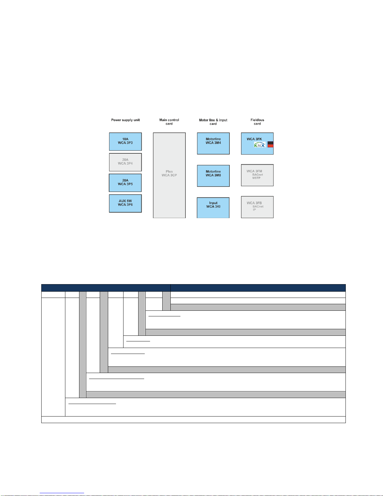
Cards
Each MotorController contains a power supply unit (SMPS), either a WCA 3P3 or a WCA 3P5 for the 10A or 20A version
respectively, as well as a 5W auxiliary power supply for wind / rain sensor. Aside from the power supply units the Standard
version also includes a motorline card type WCA 3M4 or WCA 3M8 with 4 and 8 motor lines respectively and an input card
WCA 3KI with 10 inputs. Additionally, the Standard version is also available in a version with fieldbus interface for KNX.
If additional motor lines, inputs or fieldbus connection is required a Plus version of the MotorController is necessary.
Motor groups and motor lines
A motor group consists of one or more motor lines and all the motor lines are operated simultaneously.
All motor lines on the motor cards (WCA 3M4 & WCA 3M8) can be configured for either a ±24V standard actuators or
MotorLink® actuators. A motor group can contain motor lines with both ±24V standard actuators and MotorLink® actuators,
whereas a motor line only can have ±24V standard or MotorLink® actuators connected.
3 Variants of MotorControllers
Item composing
WCC 3
xx x xx
xx xxx 01
01 = Product version number
Fieldbus card
” ” = No fieldbus card
KNX = Fieldbus card with interface to KNX
Input card
10 = Input card with 10 inputs
Motorline card
04 = Motor line card with 4 motor lines
08 = Motor line card with 8 motor lines
MotorController version
S = Standard
P = Plus
MotorController size
10 = 10A
20 = 20A
MotorController series 3
5
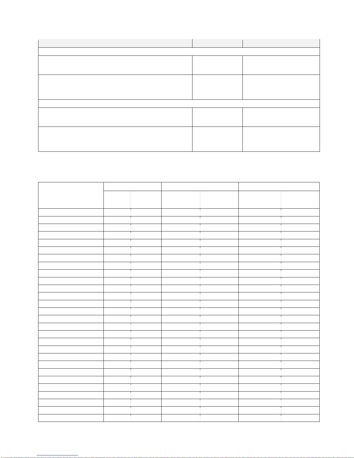
3.1 MotorController versions
Number of motor lines and other functions
Cards
Item number
WCC 310 versions
Standard version
4 motor lines
10 keypads / inputs
1 x WCA 3M4
1 x WCA 3KI
WCC 310 S 0410 01
Standard version
4 motor lines
10 keypads / inputs
KNX interface
1 x WCA 3M4
1 x WCA 3KI
1 x WCA 3FK
WCC 310 S 0410 KNX 01
WCC 320 versions
Standard version
8 motor lines
10 keypads / inputs
1 x WCA 3M8
1 x WCA 3KI
WCC 320 S 0810 01
Standard version
8 motor lines
10 keypads / inputs
KNX interface
1 x WCA 3M8
1 x WCA 3KI
1 x WCA 3FK
WCC 320 S 0810 KNX 01
3.2 Max numbers of actuators per motor line and MotorContoller
The table shows the maximum number of actuators, which can be connected per motor line and MotorController depending on the
type of the actuators, MotorController and connected cards. The total power consumption of all the connected actuators must not
exceed 10A or 20A depending on MotorController size.
Per motorline
Per 10A MotorController
Per 20A MotorController
± 24V
Actuators
MotorLink®
Actuators
± 24V
Actuators
MotorLink®
Actuators
(4 Motorlines)
± 24V
Actuators
MotorLink®
Actuators
(8 Motorlines)
WMS 306-1
10 4 10
10
20
20
WMS 306-2
10 2 10 8 20
16
WMS 306-3
9 3 9 9 18
18
WMS 306-4
8 4 8 8 20
20
WMS 309-1
10 4 10
10
20
20
WMS 309-2
10 2 10 8 20
16
WMS 309-3
9 3 9 9 18
18
WMS 309-4
8 4 8 8 20
20
WMS 409 xxxx 01
5 0 5 0 10
0
WMS 409-1
5 4 5 5 10
10
WMS 409-2
4 2 4 4 10
10
WMS 409-3
3 3 3 3 9
9
WMS 409-4
4 4 4 4 8
8
WMS 515 2 0 2 0 4 0
WMU 836-1
10 4 10
10
20
20
WMU 836-2
10 2 10 8 20
16
WMU 836-3
9 3 9 9 18
18
WMU 836-4
8 4 8 8 20
20
WMU 861-1
6 4 6 6 12
12
WMU 861-2
6 2 6 6 12
12
WMU 861-3
6 3 6 6 12
12
WMU 861-4
4 4 4 4 12
12
WMU 842 / 862 / 882-1
4 4 4 4 8
8
WMU 842 / 862 / 882-2
4 2 4 4 8
8
WMU 842 / 862 / 882-3
3 3 3 3 6
6
WMU 842 / 862 / 882-4
4 4 4 4 8
8
WMU 863 / 883-1
3 3 3 3 6
6
WMU 863 / 883-2
2 2 2 2 6
6
6
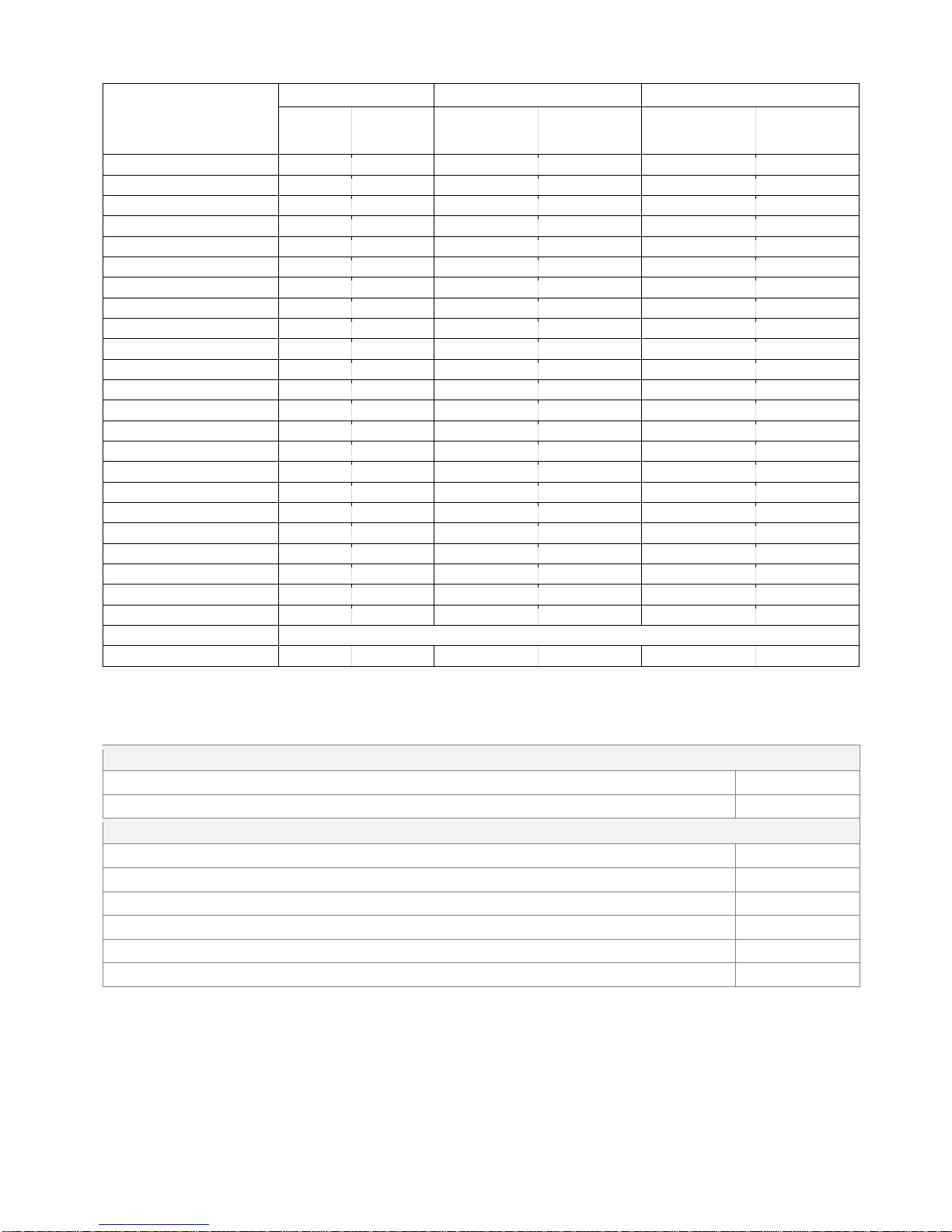
Per motor line
Per 10A MotorController
Per 20A MotorController
± 24V
Actuators
MotorLink®
Actuators
± 24V
Actuators
MotorLink®
Actuators
(4 Motor lines)
± 24V
Actuators
MotorLink®
Actuators
(8 Motor lines)
WMU 863 / 883-3
3 3 3 3 6
6
WMU 863 / 883-4
0 0 0 0 0
0
WMU 864 / 884-1
2 2 2 2 4
4
WMU 864 / 884-2
2 2 2 2 4
4
WMU 864 / 884-3
0 0 0 0 0
0
WMU 864 / 884-4
0 0 0 0 0
0
WMU 885 / 895-1
2 2 2 2 4
4
WMU 885 / 895-2
2 2 2 2 4
4
WMU 885 / 895-3
0 0 0 0 0
0
WMU 885 / 895-4
0 0 0 0 0
0
WMX 503 / 504 / 523 / 526-1
20 4 20
16
40
32
WMX 503 / 504 / 523 / 526-2
20 2 20 8 40
16
WMX 503 / 504 / 523 / 526-3
18 3 18
12
39
24
WMX 503 / 504 / 523 / 526-4
20 4 20
16
40
32
WMX 803 / 804 / 823 / 826-1
10 4 10
10
20
20
WMX 803 / 804 / 823 / 826-2
10 2 10 8 20
16
WMX 803 / 804 / 823 / 826-3
9 3 9 9 18
18
WMX 803 / 804 / 823 / 826-4
8 4 8 8 20
20
WML 820/825
10 0 10 0 20
0
WML 860-1
10 4 10
10
20
20
WML 860-2
10 2 10 8 20
16
WML 860-3
9 3 9 9 18
18
WML 860-4
8 4 8 8 20
20
WMB 801/802*
max. 4A connected to WMB
WMB 811/812 */**
10 2 10 8 20
16
* Do not exceed the total power consumption of the motor line
** When having two locking actuators per motor line, it must be one of each type: 1 x WMB 811 and 1 x WMB 812
4 Accessories and spare parts
Accessories
Rain sensor
WLA 331
Rain/wind speed sensor
WLA 330
Spare parts
10A power supply unit for WCC 310
WCA 3P3
20A power supply unit for WCC 320
WCA 3P5
5W 230 AC / 24V DC – 24V AUX supply for sensors
WCA 3P6
Motor line card with 4 motor lines incl cover
WCA 3M4
Motor line card with 8 motor lines incl cover
WCA 3M8
Input card with 10 inputs for e.g. comfort keypad incl. cover
WCA 3KI
 Loading...