

Window Master WCC 310 UL, WCC 320 UL Installation Instructions Manual
US
+1 650 543 8166
info.us@windowmaster.com
Other markets
+45 4567 0300
info@windowmaster.com
www.windowmaster.com
WCC 3xx install 1711-Firmware v123 UL - UK ©WindowMaster 2016, 2017 ®WindowMaster is a registred trademark used under the license by WindowMaster International A/S
WindowMasterInternational A/S, Skelstedet 13, DK-2950 Vedbæk
WCC 310 & WCC 320 UL
Plus versions
Installation instruction
UL MotorController
(Version 1711 – for firmware from version 1.23 (main card) &
from version 1.06 (motor line card))
Save this installation instruction to the end user

2
1 Safety information ........................................................................................................................................................ 4
Safety ................................................................................................................................................................ 4
120V AC ............................................................................................................................................................ 4
Application ......................................................................................................................................................... 4
Cable routing and electrical connection ............................................................................................................. 4
2 Structure of the MotorController ................................................................................................................................ 5
3 Variants of MotorControllers ....................................................................................................................................... 6
MotorController version ..................................................................................................................................... 6
Max numbers of actuators per motor line and
MotorController ............................................................................. 6
4 Accessories and spare parts ...................................................................................................................................... 7
5 Technical data .............................................................................................................................................................. 8
6 Mounting ....................................................................................................................................................................... 9
7 Installation .................................................................................................................................................................... 9
Cable routing ..................................................................................................................................................... 9
Cables into housing ........................................................................................................................................... 9
Connection of safety earth wire and 120V AC ................................................................................................... 9
Installation of the ventilation keypad .................................................................................................................. 9
Assembly instructions ........................................................................................................................................ 9
8 Cable dimensioning ................................................................................................................................................... 10
Max. cable Length ............................................................................................................................................10
8.1.1 Formula for the calculation of the maximum actuator cable length ............................................................. 10
8.1.2 Max cable length – ±24V standard actuators .............................................................................................. 10
8.1.3 Max cable length – actuators with MotorLink® ............................................................................................. 11
9 Cable plan for connection to WCC 310 / 320 Plus version ..................................................................................... 12
10 Description of cards and mains connection ............................................................................................................ 13
WCC connection to mains and power supply units – WCA 3P3, WCA 3P4 and WCA 3P6 .............................13
Connections between cards .............................................................................................................................13
Main control card WCA 3CP – Plus Version ....................................................................................................14
Motor line card – WCA 3M4 / WCA 3M8 ..........................................................................................................21
Keypad card – WCA 3KI ..................................................................................................................................22
Power supply card – WCA 3P6 ........................................................................................................................23
Fieldbus cards ................................................................................................ ..................................................23
11 Touch screen .............................................................................................................................................................. 24
Icons .................................................................................................................................................................24
Rotation of the touch screen ............................................................................................................................25
12 Configuration – main menu ....................................................................................................................................... 25
Motor lines – motor groups ...............................................................................................................................25
12.1.1 Examples with motor lines / motor groups ................................................................................................... 25
Motor line .........................................................................................................................................................26
12.2.1 Motor line - numbering ................................................................................................................................ 26
12.2.2 Motor line - configuration ............................................................................................................................. 26
12.2.3 Colour code - motor line .............................................................................................................................. 27
Motor group ......................................................................................................................................................27
12.3.1 Motor group - configuration ......................................................................................................................... 27
12.3.2 Colour code – motor group .......................................................................................................................... 27
Local input ........................................................................................................................................................28
12.4.1 Numbering of local inputs ............................................................................................................................ 28
3
12.4.2 Local input - configuration ........................................................................................................................... 28
12.4.3 Usage of wind/rain sensors - WLA 33x ...................................................................................................... 29
Local output ......................................................................................................................................................29
12.5.1 Numbering of local output ........................................................................................................................... 29
12.5.2 Local output - configuration ......................................................................................................................... 30
Weather station type ........................................................................................................................................30
Sequence control .............................................................................................................................................31
WSK-Link™ - master/slave connection ............................................................................................................32
Network ............................................................................................................................................................32
Log in ...............................................................................................................................................................33
Configuration files on USB ...............................................................................................................................34
System .............................................................................................................................................................35
Fieldbus (KNX and BACnet) .............................................................................................................................35
12.13.1 KNX configuration ....................................................................................................................................... 35
12.13.2 BACnet configuration .................................................................................................................................. 36
13 Status – main menu ................................................................................................................................................... 36
14 Manual operation and main menu ............................................................................................................................ 37
15 Configuration missing – main menu ........................................................................................................................ 37
16 Hardware error – main menu ..................................................................................................................................... 37
17 View all details – main menu ..................................................................................................................................... 37
18 Remote control of MotorController .......................................................................................................................... 38
19 Commissioning and test run ..................................................................................................................................... 38
The MotorController is completely installed, without the operating voltage applied .........................................38
With mains voltage ...........................................................................................................................................39
Ventilation keypad ............................................................................................................................................39
Wind/rain detector ............................................................................................................................................39
20 Maintenance ............................................................................................................................................................... 39
Maintenance agreements .................................................................................................................................39
Replacement cards ..........................................................................................................................................39
20.2.1 Replacement of 3M4, 3M8 and 3KI cards ................................................................................................... 39
20.2.2 Replacement of 3CP card ........................................................................................................................... 39
21 Declaration of Conformity ......................................................................................................................................... 39

4
1 Safety information
Safety
Only allow correspondingly trained, qualified and skilled personnel to carry out installation work.
Reliable operation and the avoidance of damage and hazards are only guaranteed if installation and settings are carried out
carefully in accordance with these instructions.
There may be personal danger by electrically operated windows:
- the forces occurring in the automatic mode can be such that parts of the body could get crushed
- when opened, actuators (spindles) could protrude into the room
For this reason, measures have to be taken prior to starting up the actuators, which exclude the danger of injury.
For safety reasons we recommend to install opening restrictors on bottom-hung windows.
In the event that windows are subjected to rain and/or high wind loads, we recommend connecting a wind/rain sensor to the
MotorController for the automatically closing of the windows.
The MotorController is to be located in a safe place, protected from the effects of fire and smoke.
The MotorController is to be surface mounted.
The MotorController is supplied by 120 V AC
The manufacturer does not assume any liability for possible damage resulting from inappropriate use.
120V AC
120V AC can cause death, severe injury or considerable damage to assets.
The connection of the MotorController is reserved for qualified personnel.
Disconnect all poles of the MotorController from the supply voltage prior to opening, installation or assembling.
Installation and use according to the national regulations.
Application
The MotorController is exclusively designed for the automatic opening and closing of windows, flaps or doors.
Always check that your system meets the valid national regulations.
Pay particular attention to the opening cross section, the opening time and opening speed.
The cable cross sections depend on the cable length and current consumption (amperage).
Cable routing and electrical connection
Fuse the 120VAC power supply cable separately on site.
Cable routing and connection - adhere to national regulations.
Establish the cable types, if necessary, with the local approval bodies.
Do not conceal flexible cables.
Junction box must be accessible for maintenance purposes.
Disconnect all poles of the mains voltage prior to starting maintenance work or making changes to the system.
Secure the system to prevent unintentional switching on again.
Route all low voltage cables (24VDC) separate from the power current cables.
Design cable types, lengths and cross sections in accordance with the technical information.
Cable specifications is a guide only, the overall responsibility resides with the electrical contractor on site.
Installation must be in accordance with the national electrical regulations.
5
2 Structure of the MotorController
Sizes & Versions
The WCC 310 and WCC 320 MotorControllers are available in two different versions namely a Standard and a Plus version.
This installation instruction only deals with the Plus versions. Please see separate installation instruction for the Standard
versions of WCC 310 and WCC 320.
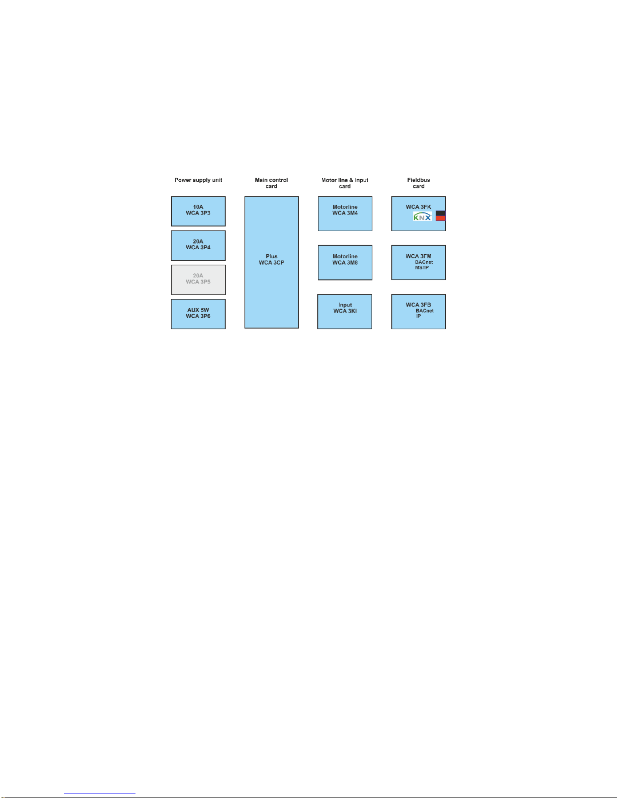
Cards
Each MotorController contains a power supply unit (SMPS), either a WCA 3P3 or a WCA 3P4 for the 10A or 20A version
respectively, as well as a 5W auxiliary power supply. Aside from the power supply unit the Plus version also includes a main
control card type WCA 3CP, which includes a touch screen for easy configuration of the MotorController. Motor line and input
cards, as well as fiedbus cards, can be added to the MotorController depending on requirements.
Selection of cards
The Main control card type WCA 3CP allows connections of 2 motor lines and 2 keypads. If more than 2 motor lines or 2
keypads are required, the necessary cards can be added.
Cards:
- WCA 3M4 motor line card, allows additional 4 motor lines.
- WCA 3M8 motor line card, allows additional 8 motor lines.
- WCA 3KI input card, allows additional 10 keypads (requires WCA 3M4 or WCA 3M8).
A fieldbus card must be added, if communication via KNX or BACnet is required.
Fieldbus cards:
- WCA 3FK fieldbus card, fieldbus interface for KNX
- WCA 3FM fieldbus card, fieldbus interface for BACnet / MSTP
- WCA 3FB fieldbus card, fieldbus interface for BACnet IP
Installation of cards may only be done when there is no power on the MotorController. Motor line and input cards are ordered
together with the MotorController and mounted to the MotorController from the factory side, whereas the fieldbus cards are
delivered as individual products and are to be mounted by the customer – see separate installation manual for mounting of
fieldbus card.
The item no. of the MotorController specifies the type and mounting of the cards - see "Variants of MotorController" for more
information
Motor groups and motor lines
A motor group consists of one or more motor lines and all the motor lines are operated simultaneously.
The motor lines on both the main control card (WCA 3CP) and the motor line cards (WCA 3M4 or WCA 3M8) can all be
configured for either a ±24V standard actuators or MotorLink® actuators. A motor group can contain motor lines with both ±24V
standard actuators and MotorLink® actuators, whereas a motorline only can have ±24V standard or MotorLink® actuators
connected.
Adding MotorControllers
The natural ventilation installation can be expanded by adding more MotorControllers and creating a master/slave connection
among them. The master/slave connection is done directly on the WSA 3CP card. The total cable length between 2
MotorControllers must not exceed 200m.
6
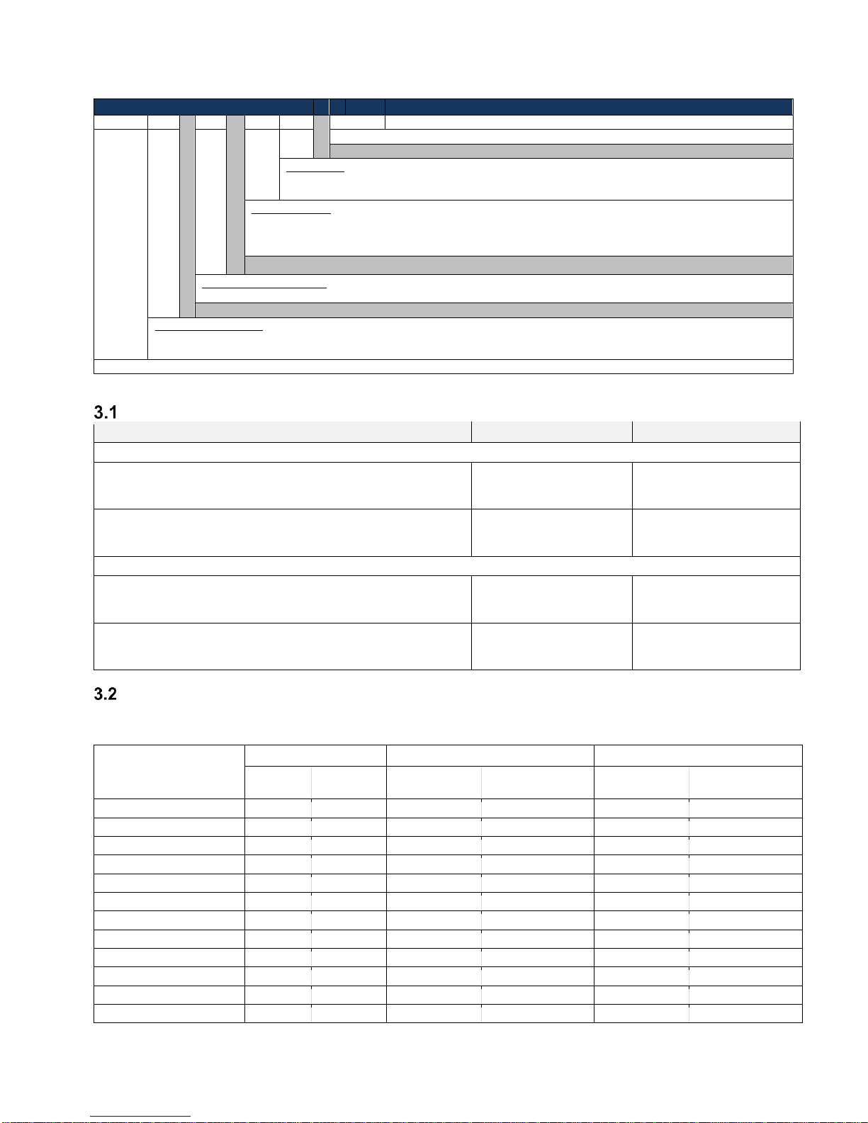
3 Variants of MotorControllers
Item composing
WCC 3
xx P xx
xx U1
U1 = UL Std. 325 and product version number 1
Input card*
02 = No input card
12 = Input card (10 additional keypad inputs)
Motor line card
02 = No motor line card
06 = Motor line card (4 additional lines)
10 = Motor line card (8 additional lines)
MotorController version
P = Plus
MotorController size
10 = 10A
20 = 20A
MotorController series 3
*requires a motor line card
MotorController version
Number of motor lines and other functions
Cards
Item number
WCC 310 versions
Plus version
2 motor lines
2 keypads / inputs
1 x WCA 3CP
WCC 310 P 0202 U1
Plus version
10 motor lines
12 keypads / inputs
1 x WCA 3CP
1 x WCA 3M8
1 x WCA 3KI
WCC 310 P 1012 U1
WCC 320 versions
Plus version
6 motor lines
12 keypads / inputs
1 x WCA 3CP
1 x WCA 3M4
1 x WCA 3KI
WCC 320 P 0612 U1
Plus version
10 motor lines
12 keypads / inputs
1 x WCA 3CP
1 x WCA 3M8
1 x WCA 3KI
WCC 320 P 1012 U1
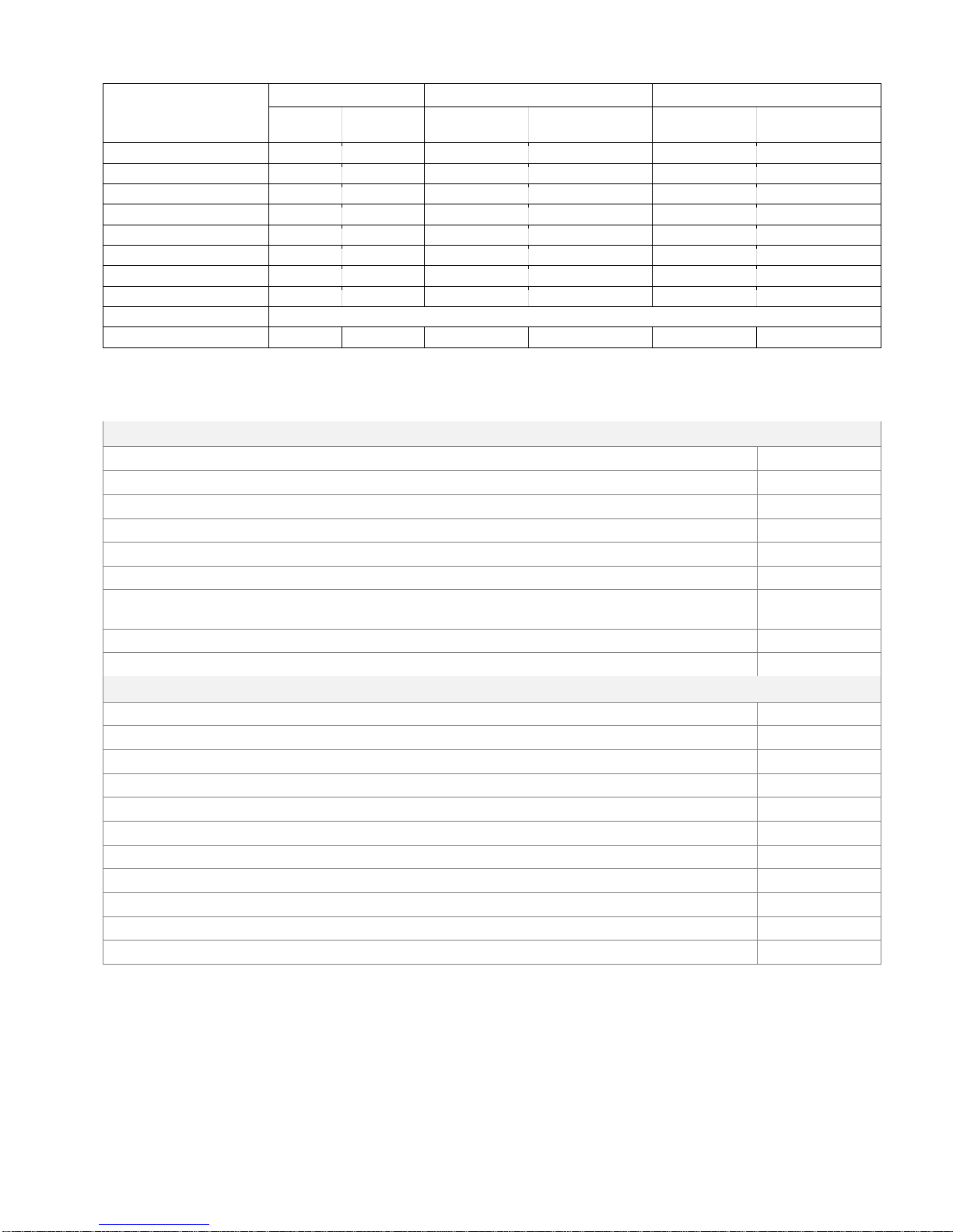
Max numbers of actuators per motor line and
MotorController
The table shows the maximum number of actuators, which can be connected per motor line and MotorController depending on the
type of the actuator, MotorController and connected card. The total power consumption of all the connected actuators must not
exceed 10A for WCC 310 and 20A for WCC 320.
Per motor linie
Per 10A MotorController
Per 20A MotorController
± 24V
actuators
MotorLink®
actuators
± 24V actuators
MotorLink® actuators
(10 Motor lines)
± 24V actuators
MotorLink® actuators
(10 Motor lines)
WMU 836-1
4 4 10
10
20
20
WMU 836-2
4 2 10
10
20
20
WMU 836-3
3 3 9 9 18
18
WMU 836-4
4 4 8 8 20
20
WMU 861-1
4 4 6 6 12
12
WMU 861-2
4 2 6 6 12
12
WMU 861-3
3 3 6 6 12
12
WMU 861-4
4 4 4 4 12
12
WMU 842 / 862 / 882-1
4 4 4 4 8
8
WMU 842 / 862 / 882-2
4 2 4 4 8
8
WMU 863 / 883-1
3 3 3 3 6
6
WMU 864 / 884-1
1 1 2 2 4
4
7
Per motor linie
Per 10A MotorController
Per 20A MotorController
± 24V
actuators
MotorLink®
actuators
± 24V actuators
MotorLink® actuators
(10 Motor lines)
± 24V actuators
MotorLink® actuators
(10 Motor lines)
WMX 503 / 504 / 523 / 526-1
8 4 20
20
40
40
WMX 503 / 504 / 523 / 526-2
8 2 20
16
40
20
WMX 503 / 504 / 523 / 526-3
6 3 18
18
39
30
WMX 503 / 504 / 523 / 526-4
8 4 20
20
40
40
WMX 803 / 804 / 823 / 826-1
4 4 10
10
20
20
WMX 803 / 804 / 823 / 826-2
4 2 10
10
20
20
WMX 803 / 804 / 823 / 826-3
3 3 9 9 18
18
WMX 803 / 804 / 823 / 826-4
4 4 8 8 20
20
WMB 801/802*
max. 4A tilsluttet på WMB
WMB 811/812 */**
4 2 10
10
20
20
* Do not exceed the total power consumption of the motor line
** When having two locking actuators per motor line, it must be one of each type: 1 x WMB 811 and 1 x WMB 812
4 Accessories and spare parts
Accessories
Fieldbus card with field bus interface for KNX incl. cover – sold separately, not factory mounted
WCA 3FK
Fieldbus key with field bus interface for BACnet / MSTP incl. cover - sold separately, not factory mounted
WCA 3FM
Fieldbus card with field bus interface for BACnet-IP incl. cover - sold separately, not factory mounted
WCA 3FB
Rain sensor
WLA 331
Rain/wind speed sensor
WLA 330
Rain/wind speed sensor, with pulse output
WLA 340
Wind speed sensor & Wind direction sensor
WOW 201 &
WOW 202
Bracket for junction box
WOW 203
Junction box for WOW 201 and WOW 202
WOW 204
Spare parts
10A power supply unit for WCC 310
WCA 3P3
20A power supply unit for WCC 320
WCA 3P4
5W 120 AC / 24V DC
WCA 3P6
Main control card for Plus version WCC 310 / WCC 320 incl. cover
WCA 3CP
Motor line card with 4 motor lines incl. cover
WCA 3M4 UL
Motor line card with 8 motor lines incl. cover
WCA 3M8 UL
Input card with 10 inputs for e.g. key pads incl. cover (requires WCA 3M4 or WCA 3M8)
WCA 3KI
Plastic covers for the cards in the WCC 310 / WCC 320 Plus version
WCA 301
Fieldbus card with field bus interface for KNX incl. cover
WCA 3FK
Fieldbus card with field bus interface for BACnet / MSTP incl. cover
WCA 3FM
3.15A fuse for motorline, 10 pcs (Littelfuse 807 13150440)
WCA 308
8
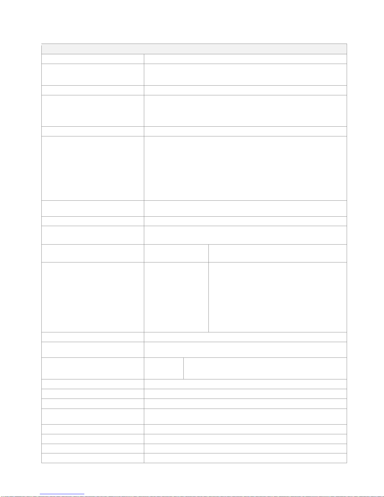
5 Technical data
Technical data
Output current (nominal)
WCC 310: 10A / WCC 320: 20A
Secondary voltage
Voltage 24V DC (±15%)
Open circuit voltage (no load) 27.6V DC @ 20°C
Ripple at max load max. 6% (3.5Vpp)
AUX
24V DC, 0.23A
Motor lines
Motor groups
WCC 310 0202: max 2, WCC 320 1012: max 10
A motor line can contain either ±24V standard or MotorLink® actuators
WCC 310 0202: max 2, WCC 320 1012: max 10
Via the touch screen motor motorlines can be connected in the same group
Primary voltage
120V AC, 60Hz (85-264V AC, 47-63Hz)
Power consumption
Idle consumption
WCC 310: min 2W1, typ. 4.2W
2
WCC 320: min 2W1, typ. 5W3
1) min.: 1 MotorLink® actuator
2) min.: 20 MotorLink® actuators + rain sensor
3) min.: 40 MotorLink® actuators + rain sensor
Max:
WCC 310: At max load 305W
WCC 320: At max load 605W
Inrush current on primary site
70A<5ms. Max 3 x WCC 310/320 per 10 A supply group.
Circuit breaker “C” characteristic.
±24V change over time
min 500ms
Cable monitoring
±24V standard actuators with end of line module are monitored by closed-circuit
Actuators with MotorLink® are monitored by data communication
LED message OK and fault
Green
Yellow
CPU working
fault
Connection cable
Actuators
Other components
Mains
flexible max 6 mm² / solide max 10 mm²
Min. 22AWG, 300V, 80°C
Listed / Recognized to UL 13
min 0.2mm² / max 1.5mm²
Listed / Recognized to UL 13
Mains must be done per relevant Electrical Code.
For permanent connection (rigid or flexible 1/2’’
conduit or equivalent) use the supplied 1/2’’ adaptor
in the Knockout. Use 10, 12, or 14AWG conductors
(same size).
Operating conditions
-5°C - +40°C, for indoor only, MotorController must not be covered
Max actuator activation duration (duty
cycle)
ED 40% (4min. per 10min.)
Number of motor lines per card
WCA 3CP
WCA 3M4
WCA 3M8
2 x 10A motor line for ±24V standard or MotorLink® actuators
4 x 10A motor line for ±24V standard or MotorLink® actuators
8 x 10A motor line for ±24V standard or MotorLink® actuators
Material
Metal housing for surface mounting
Colour
White (RAL 9010)
Size
355 x 320 x 76mm (HxWxD)
Weight
WCC 310: 4kg
WCC 320: 4.8kg
Protection class
IP 20
Certification
UL 325 and CSA C22.2 no 247-14 approved
Delivery
MotorController
Note
We reserve the right to make technical changes
9
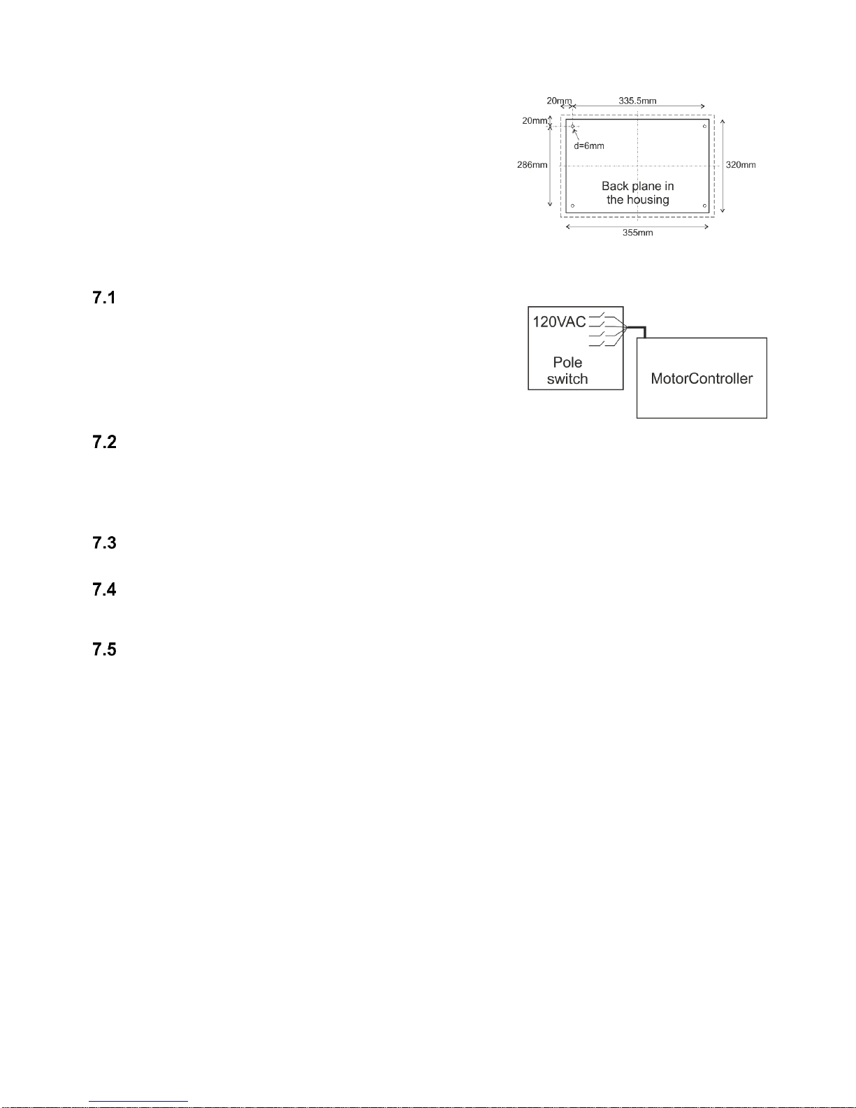
6 Mounting
The MotorController is fixed to the wall through the Ø6mm holes in
the back plane of the housing.
The MotorController is to be located in a safe place, protected from
the effects of fire and smoke.
7 Installation
Cable routing
See also chapter 8 “Cable dimensioning” in this instruction.
However, this has to be agreed with the Engineer.
Do not reduce the cable cross sections specified in the cable lengths table.
All cables of the control (except the mains supply cable) carry 24V DC and
have to be routed separate from the mains supply cable.
Adhere to the pertinent national and local regulations when routing the
cables.
Cables into housing
All connection terminals (except the mains terminals) are of the plug-in type.
Connect the connection cables in accordance with the terminal plan. Ensure that the connections are made correctly.
Incorrect cable clamping, mixing up numbers or colours could lead to malfunctions of the control MotorController or of the
external components.
Ensure that the electrical cables are always routed according to the valid national and local regulations.
Connection of safety earth wire and 120V AC
See chapter 10 ‘Description of cards’, for further description.
Installation of the ventilation keypad
Ensure that the ventilation buttons are visible and well accessible. Do not install behind protruding walls, door MotorControllers
or hidden by the building structure.
Assembly instructions
Always have assembly, installation, repair and maintenance of ventilation systems carried out by qualified personnel
trained for this purpose.
Rules to be adhered to for setting up and installation
The following safety relevant rules have to be adhered to when planning the use of a ventilation system and its set-up and
installation:
• The Provincial Building Ordinance of the provinces
Accident prevention regulations
Adhere to the general accident prevention regulations (APR), the APR for power operated windows and doors, and the
installation rules in your country.
CAUTION:
Live components are directly accessible after opening the system housing.
Prior to inserting / removing cards disconnect to the MotorController from the mains supply.
• adhere to the installation instructions and your local energy providers
• select the place of installation such that free access is guaranteed for maintenance purposes
• select cables according to regulations in this instruction - take the calculation of the actuators supply cable lengths
into account when laying the cables
• connect the cables in accordance with the drawings provided by the manufacturer
• route the cables in the building according to the regulations in this instruction
• check all system functions
10
8 Cable dimensioning
Max. cable Length
Maximum permissible cable length from the MotorController to the actuators taking into account the cable cross-section is
shown in the following tables for “± 24V standard actuators“, “MotorLink® actuators“.
8.1.1 Formula for the calculation of the maximum actuator cable length
Max. cable length = permissible voltage drop 2V (UL) x conductivity of copper(56) x cable cross section in mm2 (a)
max. actuator current total in amps (I) x 2
For both ±24V standard actuators and actuators with MotorLink® the cross section of the cable must not be less than 0.75mm2
regardless of the result of above formula.
Maximum actuator cable length: Always measured from the Motorcontroller to the last junction box + actuator cable
Permissible max. voltage drop in the line: 2 Volt
Actuating current: Sum of all actuator power consumption per motor line
Note: do not use the PE wire / green/yellow wire in the actuator cable!
Example
Max actuator cable length with cable cross section 0.75mm2 and actuator current 2A: (2 x 56 x 0.75) : (2 x 2) = 21m
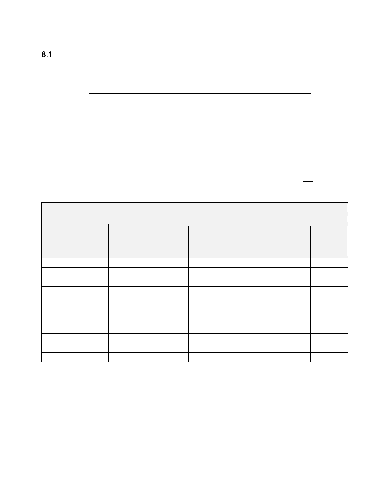
8.1.2 Max cable length – ±24V standard actuators
The actuator supply cable must have 2 wires. If monitoring is desired use min. 3: 2 wires current carrying / 1 wire for monitoring.
±24V standard actuators
Do not use the PE wire / green/yellow wire!
cable cross
section [a]
Total
actuator current [I]
3 wire
0.75mm²
3 wire
1.50 mm²
5 wire
1.50 mm²
2 wire
parallel
3 wire
2.50 mm²
5 wire
2.50 mm²
2 wire
parallel
3 wire
4.00 mm²
1A
42m
84m
168m
140m
280m
224m
2A
21m
42m
84m
70m
140m
112m
3A
14m
28m
56m
47m
93m
75m
4A
11m
21m
42m
35m
70m
56m
5A
8m
17m
34m
28m
56m
45m
6A
7m
14m
28m
23m
47m
37m
7A
6m
12m
24m
20m
40m
32m
8A
5m
11m
21m
18m
35m
28m
9A
9m
18m
15m
31m
25m
10A
8m
16m
14m
28m
22m
20A
4m
8m
7m
14m
11m
11
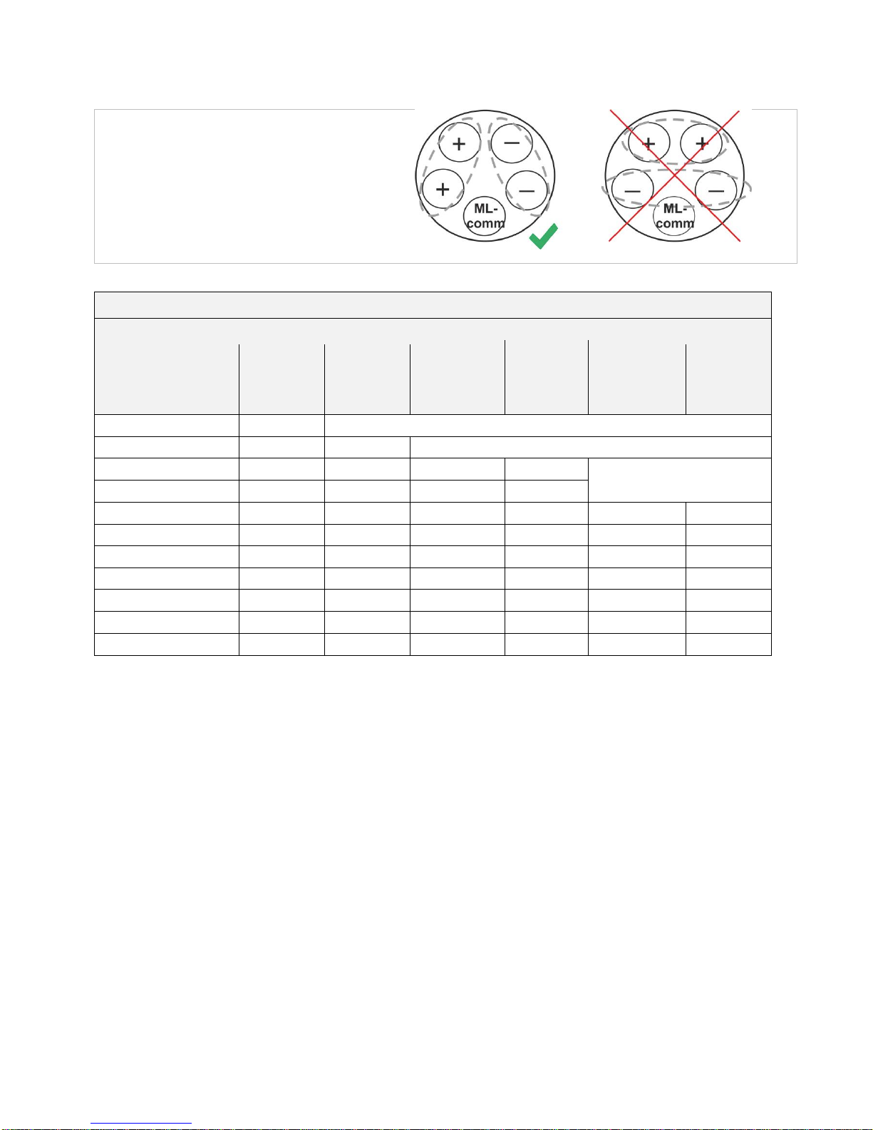
8.1.3 Max cable length – actuators with MotorLink®
The actuator supply cable must have 3 wires: 2 wires current carrying / 1 wire for communication.
When a 5 wire cable is used for MotorLink®
It is not recommended to use parallel-wire.
ML-comm = MotorLink® communication.
When using actuators with MotorLink® the max cable length is 50m regardless of the result of the above mentioned formula.
Actuators with MotorLink®
Do not use the PE wire / green/yellow wire!
cable cross
section [a]
Total
actuator current [I]
3 wire
0.75mm²
3 wire
1.50 mm²
5 wire
1.50 mm²
2 wire
parallel
3 wire
2.50 mm²
5 wire
2.50 mm²
2 wire
parallel
3 wire
4.00 mm²
1A
42m
50m
2A
21m
40m
50m
3A
14m
28m
50m
47m
50m
4A
11m
21m
42m
35m
5A
8m
17m
34m
28m
50m
45m
6A
7m
14m
28m
23m
47m
37m
7A
6m
12m
24m
20m
40m
32m
8A
5m
11m
21m
18m
35m
28m
9A
9m
18m
15m
31m
25m
10A
8m
16m
14m
28m
22m
20A
4m
8m
7m
14m
11m
12
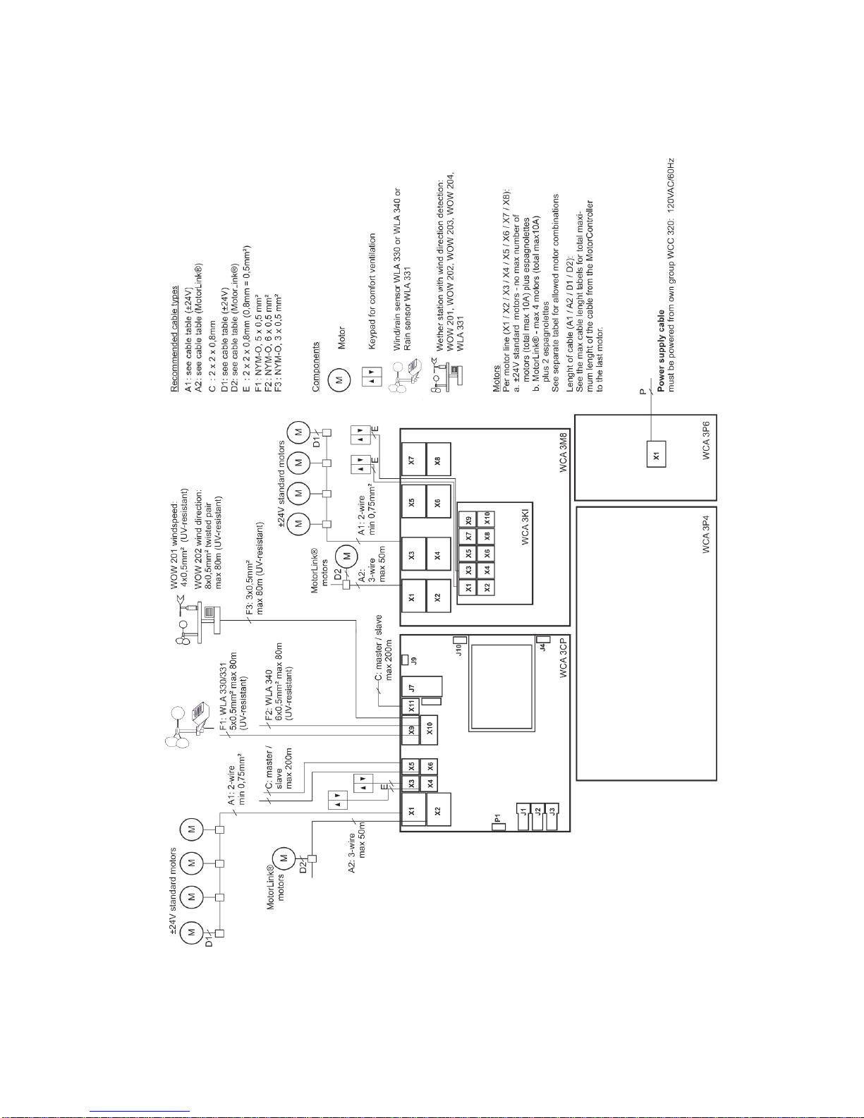
9 Cable plan for connection to WCC 310 / 320 Plus version
The above plan shows a WCC 320 MotorController
 Loading...