

Window Master futurevent Installation Instructions Manual
DK
+45 4567 0300
info.dk@windowmaster.com
www.windowmaster.com
UK & IE
+44 (0) 1536 510990
info@windowmaster.co.uk
DE
+49 (0) 5221 6940 – 500 Vertrieb / -650 Technik
info@windowmaster.de
CH
+41 (0) 62 289 22 22
info@windowmaster.ch
Other markets
+45 45 37 0300
info@windowmaster.com
FutureVent–install_WFC_WFZ_UK_DK_1602 ©WindowMaster 2016 ®WindowMaster is a registered trademark used under license by WindowMaster Group
FutureVent™
EN – Installation instruction – control unit (WFC) and Interface (WFI)
DK – Installationsvejledning – styreenhed (WFC) og interface (WFI)

2
1. EN ........................................................................................................................................3
System overview ........................................................................................................................................................... 3
Generel information ....................................................................................................................................................... 3
Electrical installation ...................................................................................................................................................... 4
Cable entries in the unit ............................................................................................................................................ 4
The connections of the FutureVent™ unit ................................................................................................................. 4
Service point ................................................................................................................................................................. 4
FutureVent™ bus connection .................................................................................................................................... 4
230V supply .............................................................................................................................................................. 5
Service gateway (used by WindowMaster
®
service engineers) ..................................................................................... 5
Checking the electrical installation ................................................................................................................................ 5
Checking the functionality of the installation when commissioned. ........................................................................... 5
Troubleshooting on the FutureVent™ installation ..................................................................................................... 6
2. DK ........................................................................................................................................6
System oversigt ............................................................................................................................................................. 6
Generelle informationer ................................................................................................................................................. 6
Elektrisk installation ....................................................................................................................................................... 7
Kabelindføringer i enheden ....................................................................................................................................... 7
FutureVent™ enhedens tilslutninger ......................................................................................................................... 7
Servicepunkt ................................................................................................................................................................. 7
FutureVent-bus forbindelse ....................................................................................................................................... 8
230V forsyning .......................................................................................................................................................... 8
Service gateway (anvendes af WindowMaster
®
serviceteknikere) ................................................................................ 8
Kontrol af elektrisk installation ....................................................................................................................................... 9
Kontrol af funktion når anlægges sættes i drift. ......................................................................................................... 9
Fejlfinding på FutureVent™ anlæg ........................................................................................................................... 9
3
1. EN
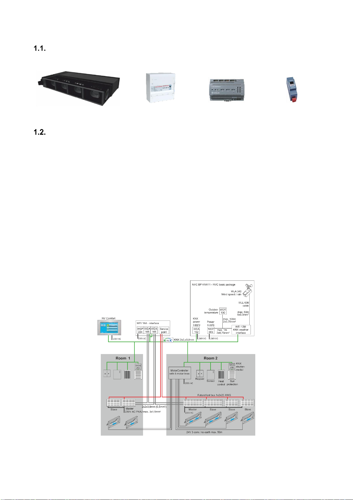
System overview
Shown below are the most common system components. In agreement with WindowMaster®, it is possible to use other
components.
FutureVent™ unit
FutureVent™
interface
SmartServer
FutureVent™ bus
termination unit
Generel information
Each FutureVent™-unit has a built in control intelligence with five analogue inputs, one analogue output and one digital output.
The units communicate mutually via FutureVent™ bus (FV-Bus) and must therefore be connected to 230V and FutureVent™
bus connection.
In each case plan the FutureVent™ bus cabling carefully. The cabling is planed together with WindowMaster®.
One installation can consist of many FutureVent™ units installed in various rooms. In each room, a WindowMaster® control unit
is connected to the analogue and digital inputs on one of the FutureVent™ units (Master).
The FutureVent™ units have a unique ID-number (Neuron ID) and before delivery, WindowMaster® programs the units. The
unique ID-number is indicated on the unit. WindowMaster® prepares and supplies documentation for each project showing
where each unit is to be place and which unit is to be connected to the control unit.
It is therefore of great importance that the FutureVent™ units are placed correct and that the control signals are
connected the right FutureVent™ unit.
Incorrect placement or wrong connected FutureVent™ units requires reprogramming of the installation in order for it to work.
The most common control signals are:
X1-X2: 0-10V for operation and air volume
X3-X10: on/off for one-way / balanced operation
Note all FutureVent™ units must be connected to 230V and the FutureVent™ bus.
1-1 Example of floor plan
 Loading...