

Wind n Go 7700, 7701, 7702, 7703, 7750 Operating Instructions
...
Emergency Light
& Communication
Center
OPERATING INSTRUCTIONS FOR
7700, 7701, 7702, 7703,
7750, 7751, 7752, 7753
ATHENA BRANDS
An Aervoe Industries, Inc. Company
Gardnerville, NV 89410 • 800-227-0196
www.athenabrands.com • mailbox@athenabrands.com
Wind ‘N Go is a registered trademark of Aervoe Industries, Inc.
7700inst; cs9/10
WIND ‘N GO FLASHLIGHT, BRITELIGHT, OR 2-WAY RADIO OPERATION
Not all Emergency Light & Communication Centers come with the same configuration of units. If
the Center that you purchased did not come with the combination that you want, you may purchase
additional Wind ‘N Go units through your local retailer or www.athenabrands.com.
3 LED Light: (#7111 or #7208)
Press the Power button:
1 time for 1 LED•
2 times for 3 LEDs•
3 times for off•
FM Scan Radio: (#7208 only)
Turn the Radio ON/OFF dial clockwise to turn on and to adjust the volume•
Extend the Antenna and adjust to obtain the best reception•
Press the Reset button to begin scanning the FM band from the beginning of the frequency•
Press the Scan button to tune in the first audible station. Continue pressing the Scan button •
until you reach your desired radio station.
When you have reached the end of the FM band, press the Reset button to return to the •
beginning of the FM frequency
Siren: (#7208 only)
Press the Siren button to activate the siren and 3 flashing LEDs•
Press again to deactivate•
Cell Phone Charging (#7111 or #7208 only):
Winding for 3 minutes will generate power for a 1-3 minute emergency phone call. •
Longer winding will produce a longer power duration. •
The Wind ‘N Go Cell Phone Adapter Kit #7995 contains connectors for many common cell phones, •
available from your local retailer or www.athenabrands.com.
2-Way Radio Operation:
For complete instructions, read the enclosed instructions for the 2-Way Radio.•
General operating specifications for use with the Emergency Light & Communication center are •
listed on the following page.
Additional 2-Way Radios may be purchased from your local retailer or www.athenabrands.com.•
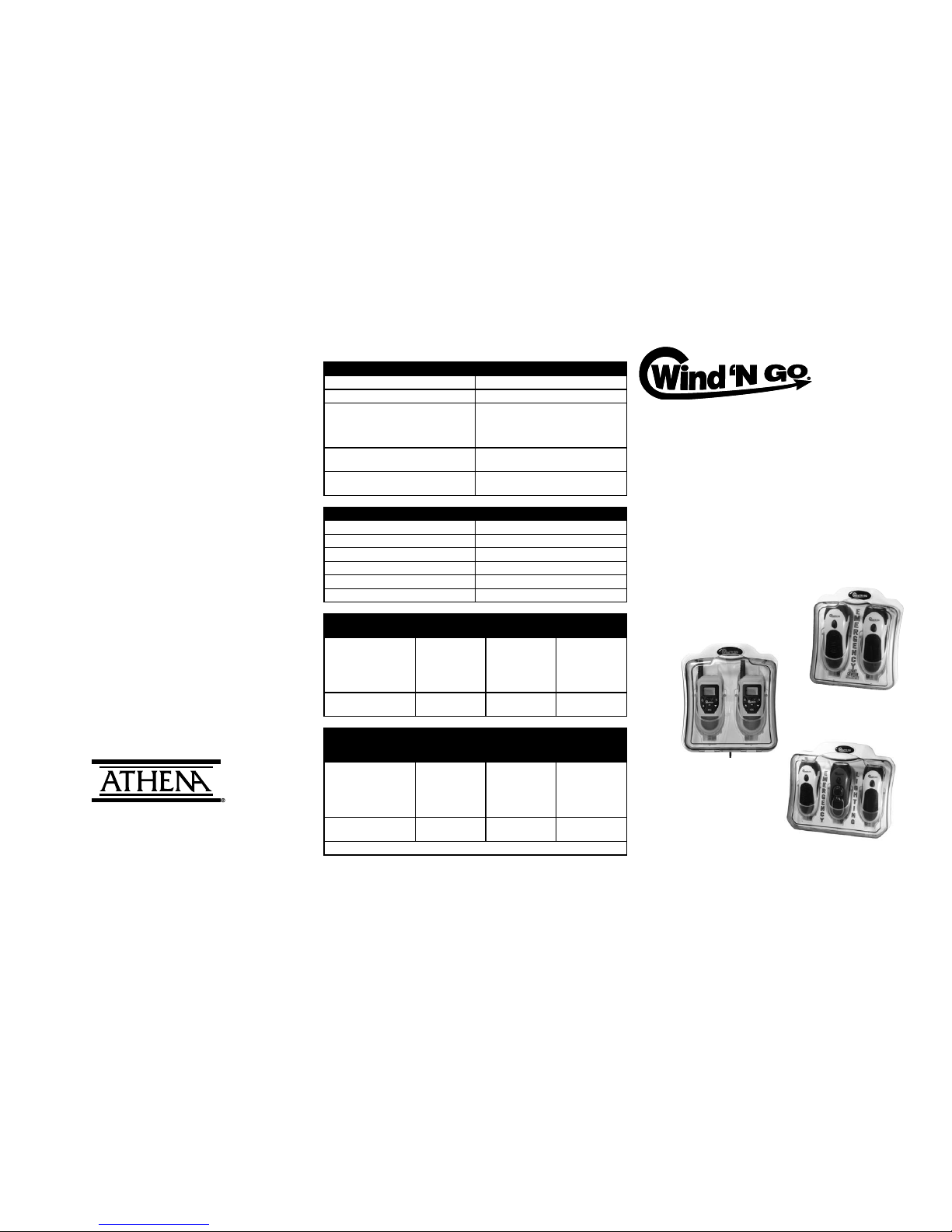
TECHNICAL INFORMATION
CHARGING CENTER SPECIFICATIONS
DC IN 6V 300 mA
DC OUT (to units) 6V 300 mA
AC/DC POWER ADAPTER UL Approved Class 2 Transformer
INPUT: 120V AC 60 Hz
OUTPUT: 6V DC 300 mA
Replacement #7991 available
DIMENSIONS 2-Station: 7.5” L x 3.25” W x 8.5” H
3-Station: 10.625” L x 3.375” W x 9.25” H
WEIGHT 2-Station: 1 lb. 11 oz.
3-Station: 2 lbs. 8 oz.
Unit FLASHLIGHT & BRITELIGHT SPECIFICATIONS
INTERNAL RECHARGEABLE BATTERY LIR 14250/300 mAH 3.6V
DC IN 6V 300 mA
DIMENSIONS 5.46” L x 2.08 “ W x 2.05” H
WEIGHT 5 oz.
SIREN (#7208 only) 105dB
RADIO BAND (#7208 only) FM 87-108.5 MHZ
CHARGING TIME/
POWER DURATION
FLASHLIGHT
(#7111 & #7208)
RADIO
(#7208 only)
SIREN
(#7208 only)
Using the charging center
to fully charge:
1 ashlight = 6 hours
2-Station center = 12 hours
3-Station center = 18 hours
1 LED = 15 hours
3 LEDs = 5 hours
12 hours 12 hours
After winding for 1 minute 1 LED = 60 minutes
3 LEDs = 30 minutes
25 minutes 30 minutes
CHARGING TIME/
POWER DURATION
2-WAY RADIO
(#7910 only)
2-LED FLASHLIGHT
(#7910 only)
EMERGENCY CELL
PHONE CHARGE
(#7910 only)
Using the charging center
to fully charge:
1, 2-Way Radio = 6 hours
2, 2-Way Radios = 12 hours
3, 2-Way Radios = 18 hours
Standby = 30-35
hours
Push To Talk = 1-2
hours
14 hours N/A
After winding for 3 minute 1-2 minutes 30 minutes 1-3 minutes talk
time
Actual times may vary depending on communication and reception variables.
Wind ‘N Go®
Emergency Light & Communications Center
#7700, 7701, 7702, 7703, 7750, 7751, 7752, 7753
READ ALL INSTRUCTIONS BEFORE INSTALLING AND OPERATING
IMPORTANT SAFEGUARDS
Mount the charging center in an indoor, dry location using the instructions provided. Mount •
according to instructions to avoid damage.
To reduce the risk of electric shock, do not submerge. All components are water resistant but •
not waterproof.
Do not install the charging center or operate units in ammable or explosive environments•
Use only Class 2 UL approved, or equivalent, AC/DC power adapter (included)•
Do not operate the charging center or components if any damage is noticed•
Do not use on electrical circuits exceeding 120V AC•
Do not look directly at the light from the ashlight; may cause injury to your eyes•
Do not operate at temperatures above 120ºF or below 32ºF•
Avoid placing near the ears when using the siren (available only on the #7208 BriteLight)•
Turn off all lights and radio features before charging•
Charging center may be cleaned with a damp cloth and followed with a clean dry cloth. Dust •
charging center regularly.
Use only Wind ‘N Go units designed for use in this charging center. Other models could cause •
damage and void the warranty.
Administer close supervision around children.•
Do not operate the 2-Way Radio within 6” (15 cm) of a person with a pacemaker. People with a •
pacemaker should not carry the 2-Way Radio in the breast pocket.
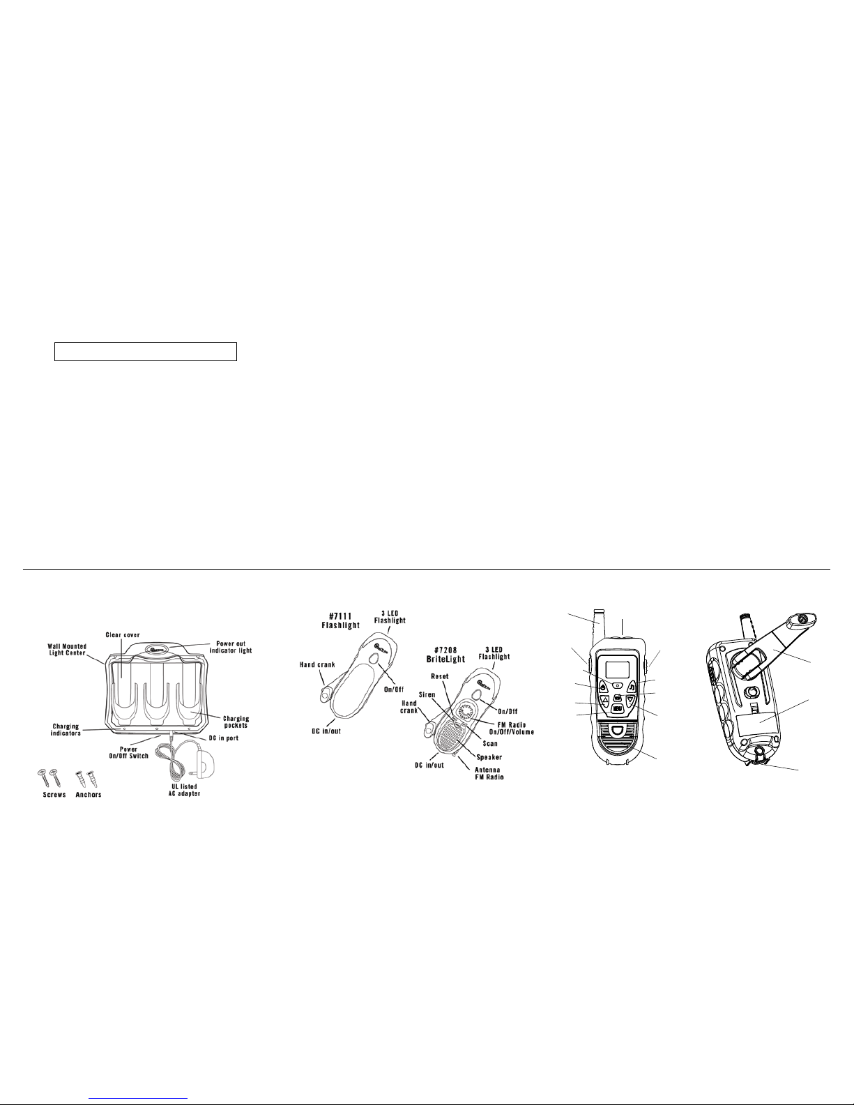
PARTS IDENTIFICATION
A 3-station charging center is shown below. A 2-station charging center is also available. Models are
available featuring a combination of #7111 Flashlights, #7208 BriteLights and #7910 2-Way Radios.
See outside of the box for the contents of your Emergency Light & Communication Center.
MATERIALS NEEDED
Pencil or Pen Tape Level Awl or drill with 9/32” drill bit
Hammer Phillips head screw driver Tape measure
MOUNTING & ASSEMBLY INSTRUCTIONS
Locate a wall within 4 feet of an electrical outlet that would be easily accessible in total 1.
darkness. The power cord should easily reach between the charging center and the outlet. An
ideal location would be near an exit door, electrical or maintenance room, laundry room, or
basement. It is not necessary to locate a wall stud to hang this unit.
Tape the included installation template on the designated wall and level. Mark the center 2.
location for the two plastic wall anchors using a pen or pencil. Remove template.
Using an awl or drill, make holes for the plastic wall anchors that are just slightly smaller than 3.
the anchor. Press the anchor into the hole until it is flush wit the surface. If necessary, gently tap
the anchor flush with a hammer.
Place the screw fastener into the opening of the anchor. Using a Phillips head screwdriver, drive 4.
the screw 3/4 of the way into the fastener, leaving 1/4" exposed to mount the charging center.
Hang the center on the two screws by aligning the two mounting holes on the back over the 5.
screws. Pull down gently to seat inside of the slots.
If the charging center does not sit flush against the wall, remove it and drive the screws into the 6.
wall a little further and hang it again. If it still does not t onto the exposed screws, then they
need to be backed out of the wall slightly. Repeat either step if necessary.
Plug the male end of the AC/DC adapter into the DC input port on the charging center and the 7.
120V AC plug into an electrical outlet.
Seat units firmly into the charging pockets with the LED lens facing up and the power button 8.
facing out. Be sure to seat it rmly onto the plug inside of the pocket.
Slide the power switch to the ON position. After this, the switch should stay in this position 9.
to keep the units charged at all times. The Wind ‘N Go power indicator light at the top and the
small LED charging indicator lights under each pocket should be illuminated.
FLASHLIGHT OPTIONS AND PARTS IDENTIFICATION
This center will accommodate a combination of
CHARGING
The charging center will fully charge completely drained units within 10-12 hours for the 1.
2-station charging center and 18 hours for the 3-station charging center. Time will vary
depending on the power stored and the number of units requiring a charge. Once fully charged,
the units will continue to receive a trickle charge so they are always ready for use.
If the power is out and the units have been used until they are completely dead, charge them up 2.
by opening the hand crank and wind for emergency stand-by use.
REMOVING AND RETURNING UNITS FROM THE CHARGING CENTER
When units are needed, open the clear protective cover and remove it by grasping and pulling 1.
upward.
To return it to the charging center, slide it into the charging pocket with the LED lens facing up and 2.
the power button facing out. Be sure to seat it rmly onto the plug inside of the charging pocket.
The LED indicator light will illuminate (see below).
INDICATOR LIGHTS
Wind ‘N Go power indicator light:
When plugged in and receiving power = steady red light•
During power outage = blinking red light so that it is easily detected in complete darkness•
Charging indicator lights: When the units are seated inside of the charging pockets, a charging
indicator light will be illuminated.
GREEN = fully charged•
RED or RED/YELLOW = charge in process or the power is out•
2-WAY RADIO OPTIONS AND PARTS IDENTIFICATION
WALL MOUNTED CHARGING CENTER
Patent Pending
Antenna
Menu
Up Key
Scan/
Monitor
Power
On/Off
Call Tone
Flashlight
On/Off
PTT Button
Flashlight
Down Key
Speaker
Microphone
AC/DC Port
Dynamo Hand
Crank
Battery
Compartment
 Loading...