

Page 1
EN
OPERATING MANUAL
INFOWIN TOUCH
LOGWIN PREMIUM TOUCH
WOOD GASIFICATION BOILER
05/2017 095182/01–v1.2.x
LogWIN
75 °C
Modulation mode
Information level
Page 2

2
Table of contents
Table of contents
1. Important information for system operators .................................................................. 4
1.1 Safety precautions ......................................................................................................................... 4
1.1.1 Caution symbols .........................................................................................................................................................4
1.1.2 General safety information .........................................................................................................................................5
1.1.3 General statement on working with and using the web server ..................................................................................5
2. InfoWIN Touch display and operating unit ..................................................................... 6
2.1 Integrated web server in the InfoWIN Touch .................................................................................... 7
2.1.1 Data protection and security ......................................................................................................................................7
2.1.1.1 Passwords ........................................................................................................................................................................... 7
2.1.1.2 Connection via the Internet ................................................................................................................................................ 7
2.1.1.3 Authorisations ..................................................................................................................................................................... 7
2.2 InfoWIN Touch menu structure ........................................................................................................ 8
2.3 LogWIN Touch menu structure for the system operator ..................................................................... 9
2.4 Basic operating functions ............................................................................................................. 10
2.5 Symbols for operation/navigation ................................................................................................. 10
2.6 How to use the InfoWIN Touch .......................................................................................................11
2.6.1 Confirmation, cancel, slider button and arrow button ............................................................................................. 11
2.6.2 Confirming selection options ................................................................................................................................... 11
2.6.3 Editing a value and/or selection ............................................................................................................................... 12
2.6.4 On-screen keyboard .................................................................................................................................................. 12
2.7 Turning on for the first time ...........................................................................................................13
2.8 Homescreen (title screen) ..............................................................................................................15
2.9 InfoWIN Touch or master control Touch basic settings .................................................................... 16
2.9.1 Language ..................................................................................................................................................................17
2.9.2 Time/date .................................................................................................................................................................17
2.9.2.1 Time format ........................................................................................................................................................................17
2.9.2.2 Date format ........................................................................................................................................................................17
2.9.2.3 Timeserver ......................................................................................................................................................................... 18
2.9.2.4 Time zone .......................................................................................................................................................................... 18
2.9.2.5 Time................................................................................................................................................................................... 18
2.9.2.6 Date ................................................................................................................................................................................... 18
2.9.2.7 Sending interval time/date ............................................................................................................................................... 19
2.9.3 Temperature format ................................................................................................................................................. 19
2.9.4 Unit of weight ...........................................................................................................................................................19
2.9.5 Display brightness .................................................................................................................................................... 19
2.9.6 Homescreen ..............................................................................................................................................................20
2.9.7 Boiler ........................................................................................................................................................................20
2.9.8 Function titles ..........................................................................................................................................................20
2.9.9 Guided start-up......................................................................................................................................................... 21
2.9.10 LAN ........................................................................................................................................................................... 21
2.9.11 MB (master control) .................................................................................................................................................. 22
2.9.12 Read system ............................................................................................................................................................. 22
2.9.13 Restart ...................................................................................................................................................................... 22
2.9.14 Factory settings ........................................................................................................................................................22
2.9.15 Device information ................................................................................................................................................... 23
Page 3

3
Table of contents
3. Operation modes ........................................................................................................ 24
3.1 OFF mode .................................................................................................................................... 24
3.2 ON mode, self-test, display OFF ................................................................................................... 25
3.3 Chimney sweeper ......................................................................................................................... 26
4. Operating phases .......................................................................................................27
5. Information level .......................................................................................................29
6. Operator level ............................................................................................................ 31
6.1 Start-up delay automatic boiler ..................................................................................................... 32
6.2 Time/date .................................................................................................................................... 33
7. Troubleshooting .........................................................................................................34
7.1 Thermal discharge safeguard ........................................................................................................ 35
7.2 LED bar ...................................................................................................................................... 35
7.3 No display on InfoWIN Touch ....................................................................................................... 35
7.4 Error messages ............................................................................................................................ 35
7.5 Alarm messages ........................................................................................................................... 36
8. For the service technician/heating technician ...............................................................38
8.1 LogWIN menu structure for service level and actuator test .............................................................. 38
8.2 Service level................................................................................................................................ 39
8.2.1 Measurement values ................................................................................................................................................ 40
8.2.2 Parameters .............................................................................................................................................................. 40
8.3 Actuator test ............................................................................................................................... 41
8.4 Starting up the integrated web server ........................................................................................... 42
8.4.1 Internet connection and router configuration ..........................................................................................................42
8.4.2 Start-up.....................................................................................................................................................................42
8.4.3 Reserved IP address ranges .....................................................................................................................................42
Page 4
4
1. Important information for system operators
1. Important information for system operators
All content of this document is the property of WINDHAGER and is therefore protected by copyright. Reproducing this
content, passing it on to others or using it for other purposes without the written consent of the owner is strictly prohibited.
Dear Heating System Owner,
On the following pages we have provided specific information and important tips regarding the operation of the boiler.
Please pay close attention to these instructions.
Familiarity with the material in this document will allow you to enjoy long-term operation of the unit. We wish you all
the best with your Windhager boiler!
Note!
The cleaning process for the boiler is described in separate LogWIN operating manual. Please also pay
close attention to these instructions. Familiarity with the material in this document will allow you to enjoy
long-term operation of the unit. We wish you all the best with your Windhager boiler!
1.1 Safety precautions
The boiler together with its accessories complies with the latest state of the art as well as the relevant safety regulations, and is operated with electric current (230 V AC). Improper installation or repair can pose the danger of life-threatening electric shock. Installation may be performed only by appropriately qualified technicians.
1.1.1 Caution symbols
Please take note of the following safety information levels in this document.
DANGER
Ignoring the warnings identified by this symbol can lead to serious injuries or death.
WARNING
Ignoring the warnings identied by this symbol can lead to injury.
CAUTION
Ignoring the warnings identified by this symbol can lead to malfunction of or damage
to the boiler or heating system.
Note!
The blocks of text identified by this symbol provide information and tips for operation.
Page 5
5
1. Important information for system operators
1.1.2 General safety information
DANGER
When performing cleaning or repair work, disconnect the power plug!
When performing cleaning or repair work or before opening the cladding and covers
for electrical and moving parts, the boiler must be de-energised for safety reasons
(e.g. by disconnecting the power plug).
WARNING
Warning of hot surface: risk of burns!
Before touching these surfaces, you must turn off the boiler and let it cool.
1.1.3 General statement on working with and using the web server
• Operation of the InfoWIN Touch as a web server requires a monthly data volume of approx. 100–300 MB, depending
on usage.
• Do not clean the InfoWIN Touch or accessories with strong chemicals, cleaning solutions or aerosols.
• Do not expose the InfoWIN Touch or accessories to extreme temperatures or fluctuations in temperature (below 0
°C or above +50 °C).
Open source licences
This product contains in part some free software distributed under GPL licence terms and/or GPL-like licences. To obtain the source code covered under those licences, please contact [email protected]. We reserve the right to demand
a small fee of EUR 80.
Page 6
6
2. InfoWIN Touch display and operating unit
2. InfoWIN Touch display and operating unit
The InfoWIN Touch display is a central display and operating unit with integrated web server for operating the boiler,
buffer load function module, heating circuit function module, etc. The function modules are only shown on the display
when they are available and in the server level set by a trained member of service personnel.
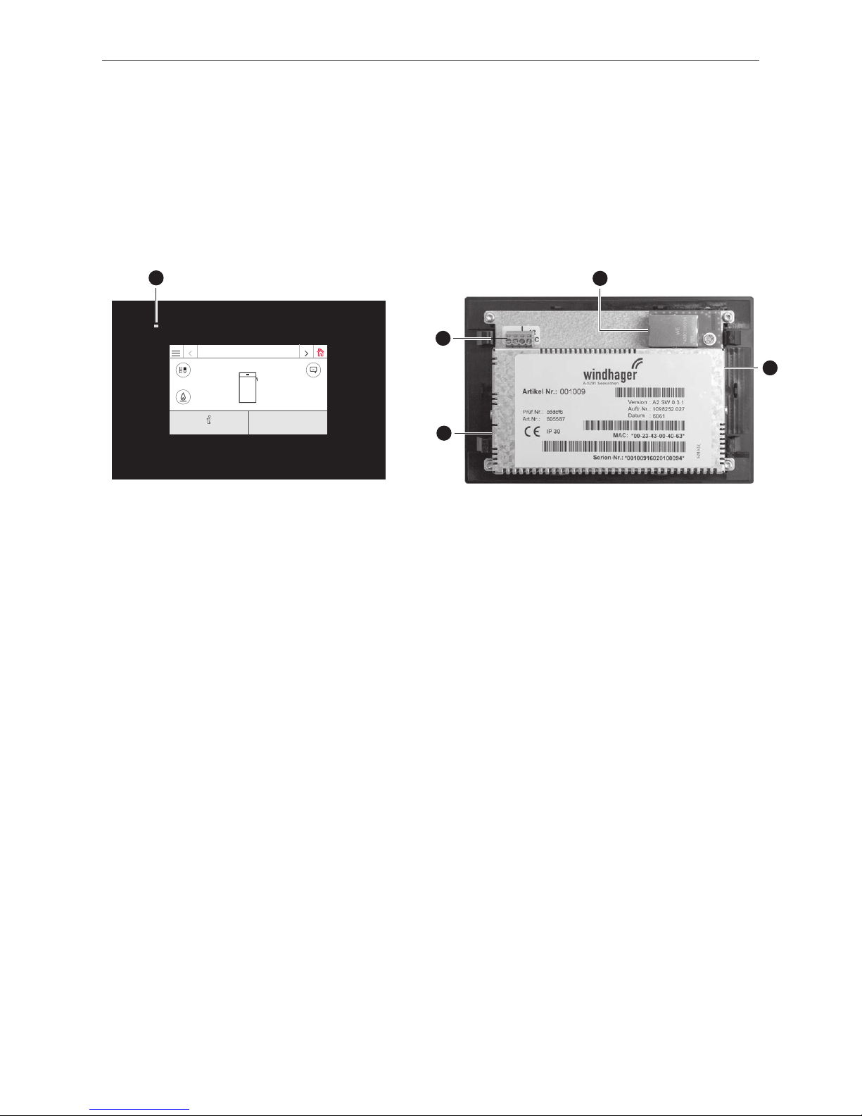
During operation, the homescreen (title screen) is displayed by default and the LED lights up green – Fig. 2. After
approx. 12min., the screensaver turns on (screen is black) and only the LED is lit up green. Pressing the touchscreen
reactivates it.
The InfoWIN Touch is fitted with a LAN and LON connection, an LED, a micro SD card and a reset button.
1 ........... LED
2 ........... Reset button
3 ........... LON connection / 12 V DC
4 .......... LAN connection
5 ........... micro SD card slot and micro SD card
2
4
5
Fig. 2 Front side of the Info Touch Fig. 3 Rear side of the Info Touch
1
3
LAN connection
There is an RJ45 socket on the InfoWIN Touch for the LAN connection. Use a standard LAN cable to connect the
InfoWIN Touch with your Internet router (Internet modem). Alternatively, the InfoWIN Touch is suited to all LAN connection types, such as Powerline and PowerLAN, also known as dLAN.
LON connection
The InfoWIN Touch is operated at an operating voltage of 12 VDC. A 4-pole cable is used to connect the InfoWIN Touch
to the boiler control panel. This cable connects the supply voltage and the LON field bus (data bus for communicating
with control components).
micro SD card
The microSD card is required for software update.
Reset button
If the reset button is pressed for more than 10 sec., the user name and password for the integrated web server in the
InfoWIN Touch are reset to the factory settings.
Factory settings:
User name: Service User name: USER
Password: 123 Password: 123
These passwords are automatically overwritten with a secure password the first time a connection is established to the
"WindhagerConnect" portal.
LogWIN
65 °C
Modulation mode
Information level
Page 7

7
2. InfoWIN Touch display and operating unit
2.1 Integrated web server in the InfoWIN Touch
The integrated web server can only be used in combination with a Windhager boiler and an MES INFINITY control system. An Internet connection (router) is needed for communication via the Internet. Operation requires a monthly data
volume of approx. 100–300 MB, depending on usage.
The integrated web server automatically connects to the "WindhagerConnect" Windhager portal once started up. This
web portal manages all data from the system owner of relevance to connections and systems. As the system owner,
you have to register with the portal using your user name (e-mail address) and a password. Then your heating system
is connected to the "WindhagerConnect" portal via the integrated web server and provides all data for the Windhager
heating app "myComfort".
You can download and install the Windhager app "myComfort" for free from app stores. Once installed, launch "myComfort". Log on with your user name (e-mail address) and password and "myComfort" connects to your heating system.
2.1.1 Data protection and security
2.1.1.1 Passwords
Please use a secure password for the portal.
It should contain at least 8 characters made up of a combination of numbers, upper case and lower case letters as well
as special characters (e.g. 123abcA!).
The password for connecting to web serverTouch is issued automatically the first time the connection is established
and is transferred to the web serverTouch. This password is secure and unique and does not have to be changed. This
password contains at least 10 characters and is also made up of numbers, upper case and lower case letters as well as
special characters.
2.1.1.2 Connection via the Internet
The web serverTouch automatically connects to the "WindhagerConnect" Windhager portal once started up. This connection is a secure VPN tunnel.
With your web browser you connect to the "WindhagerConnect" using the link provided below. Simply enter the link in
your web browser's address line.
https://connect.windhager.com
The connection between the "myComfort" app and the web serverTouch is established via the HTTPS protocol.
2.1.1.3 Authorisations
You manage data and authorisations for your system and decide who may connect to your system. The system owner
e-mails invitations to the authorised group of people and can uninvite them again if need be. Windhager Zentralheizung
GmbH has no influence on this.
Page 8
8
2. InfoWIN Touch display and operating unit
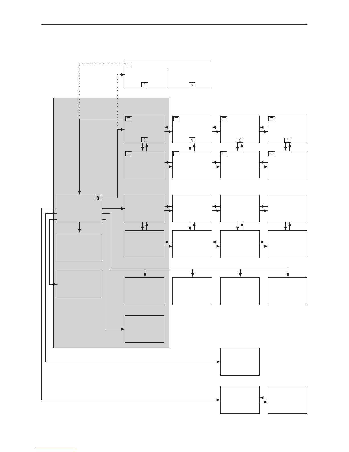
Menu
1
In the basic settings, it is possible to set whether the homescreen should be displayed as fullscreen or splitscreen, see Section 2.9.6.
Homescreen
boiler
Homescreen
heating circuit 1
function module
Homescreen
heating circuit 2
function module
Basic settings
Information level
boiler
Information level
buffer load,
cascade, etc.
Information level
heating circuit 1
function module
Information level
heating circuit 2
function module
Messages
Operator level
boiler
Operator level
buffer load,
cascade, etc.
Operator level
heating circuit 1
function module
Operator level
heating circuit 2
function module
Service level
boiler
Service level
buffer load,
cascade, etc.
Service level
heating circuit 1
function module
Service level
heating circuit 2
function module
Actuator test
boiler
Actuator test
buffer load,
cascade, etc.
Actuator test
heating circuit 1
function module
Actuator test
heating circuit 2
function module
Chimney sweeper
Hot water
program for heat-
ing circuit 1
Heating
programs
heating circuit 1
Heating
programs
heating circuit
2
Homescreen
buffer load,
cascade, etc.
Split homescreen
1
Boiler Buffer load
2.2 InfoWIN Touch menu structure
The following is described
in this manual:
Page 9
9
2. InfoWIN Touch display and operating unit
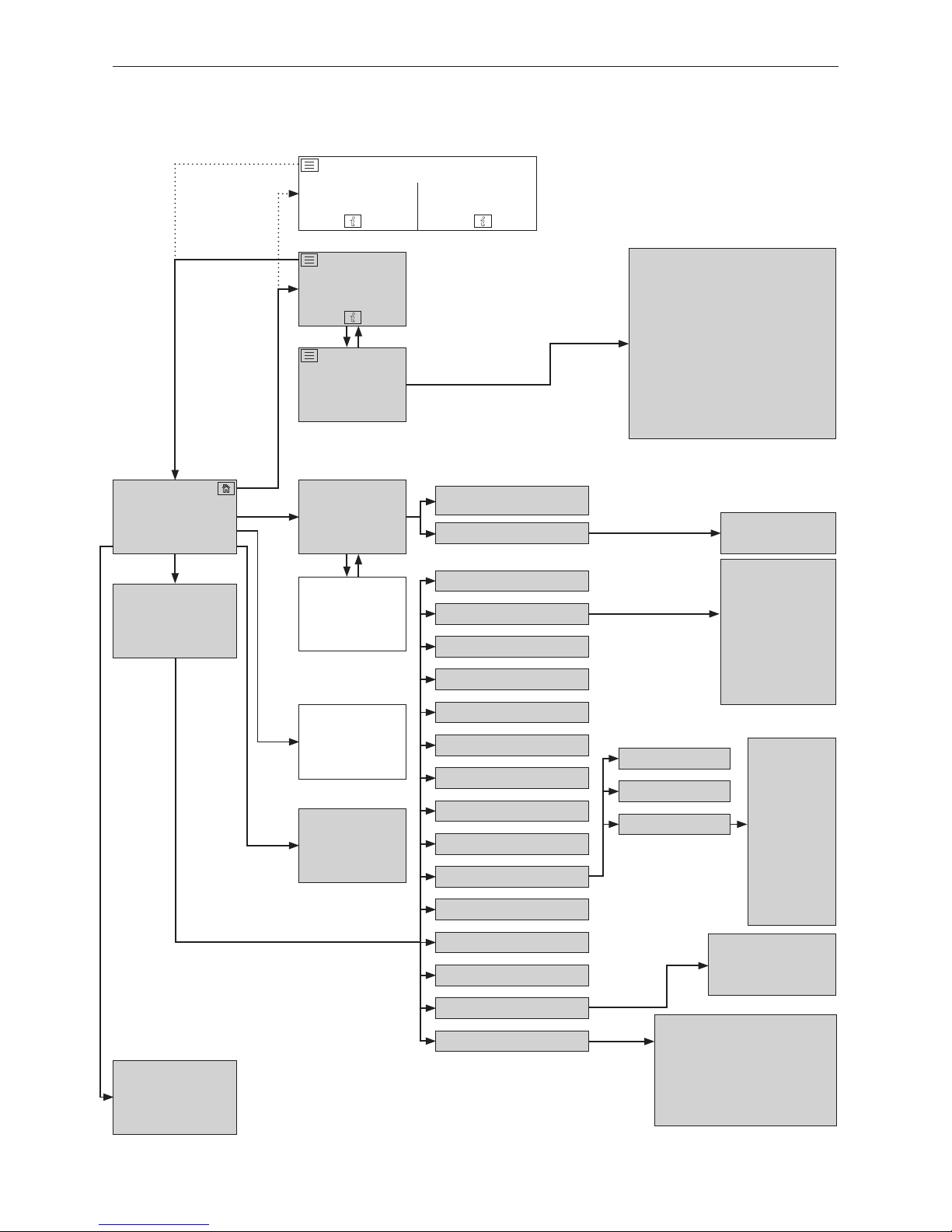
Menu
Homescreen
boiler
Basic settings
(see Section 2.9)
Information level
boiler
(see Section 5)
Messages
(see Section 7)
Operator level
boiler
(see Section 6)
Service level
boiler
(see Section 8.2)
Actuator test
boiler
(see Section 8.3)
Chimney sweeper
(see Section 3.3)
Split homescreen
1
Boiler Buffer load
2.3 LogWIN Touch menu structure for the system
operator
Top buffer temperature
Centre buffer temperature
Bottom buffer temperature
Charge status
Combustion chamber temperature
Flue gas temperature
Operating hours
Number of starts
Software version
Boiler model
Start-up delay
automatic boiler
Time / Date
Time
Date
Language
Time / Date
Temperature format
Unit of weight
Display brightness
Homescreen
Boiler
Function titles
Guided start up
LAN
MB
Read system
Restart
Factory settings
Time format
Date format
Timeserver
Time zone
Time
Date
Sending interval
time/date
No function at present
DYN IP
VPN
Alarm
Alarm URL
MAC-address
DHCP
IPV4
Subnet
Gateway
DNS
Device information
1
In the basic settings, it is possible to set whether the homescreen should be displayed as fullscreen or splitscreen, see Section 2.9.6.
LAN
LAN status
LAN settings
Software version display module
Firmware version
MAC-address
Serial number
Test number
Scan systems on restart
Page 10
10
2. InfoWIN Touch display and operating unit
2.4 Basic operating functions
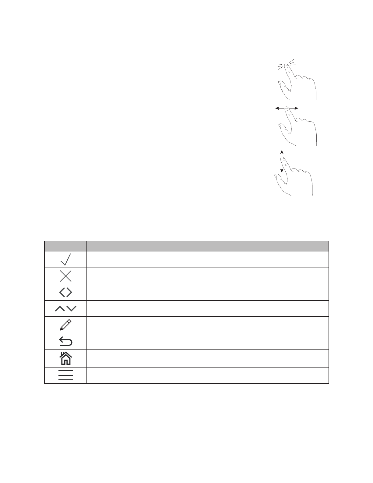
An action is triggered by touching, swiping or scrolling.
Touching:
Touch the desired area (button) with your finger and then remove your finger.
Swiping:
Place finger on the touch display and slide right or left.
You can switch between the individual modules (on the same level).
Scrolling:
Place finger on the touch display and slide up or down.
You can scroll within a level (basic settings, messages, info, operators,
service, actuator test).
2.5 Symbols for operation/navigation
The following actions are performed by touching the symbols:
Symbol Description
Confirmation; action is confirmed
Cancel; action is cancelled and you are taken back to the last step
Next; switch between the modules or sub-items
Up-down; scroll through the levels or change the values
Editing pen; point can be edited
Back; go back a step or a level
Home button; back to the homescreen
Menu button; back to the main menu
Page 11
11
2. InfoWIN Touch display and operating unit
Language selection
Dansk Deutsch English Español
Français Italiano Polski Slovenščina
2.6 How to use the InfoWIN Touch
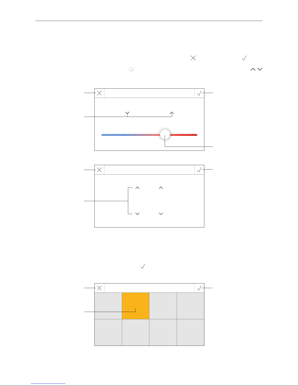
2.6.1 Confirmation, cancel, slider button and arrow button
You can cancel or confirm a selection and/or input by pressing the cancel button or confirmation button – Fig. 4,
Fig. 5.
A value is changed by moving the slider button
to the left or right (Fig. 4) or by moving the arrow buttons
(Fig. 4, Fig. 5) up or down.
2.6.2 Confirming selection options
Selection options (e.g. Fig. 6) can be specified by pressing the desired button. The selected field is highlighted. Then
save the selection by pressing the confirmation button
.
Fig. 4
Temperature
22.0 °C
5.0 °C 30.0 °C
Fig. 5
Set time
16 : 19
Fig. 6
Cancel button Confirmation button
Slider button
Arrow button
Arrow button
Cancel button
Confirmation button
Selected field
(highlighted)
Confirmation button
Cancel button
Page 12
12
2. InfoWIN Touch display and operating unit
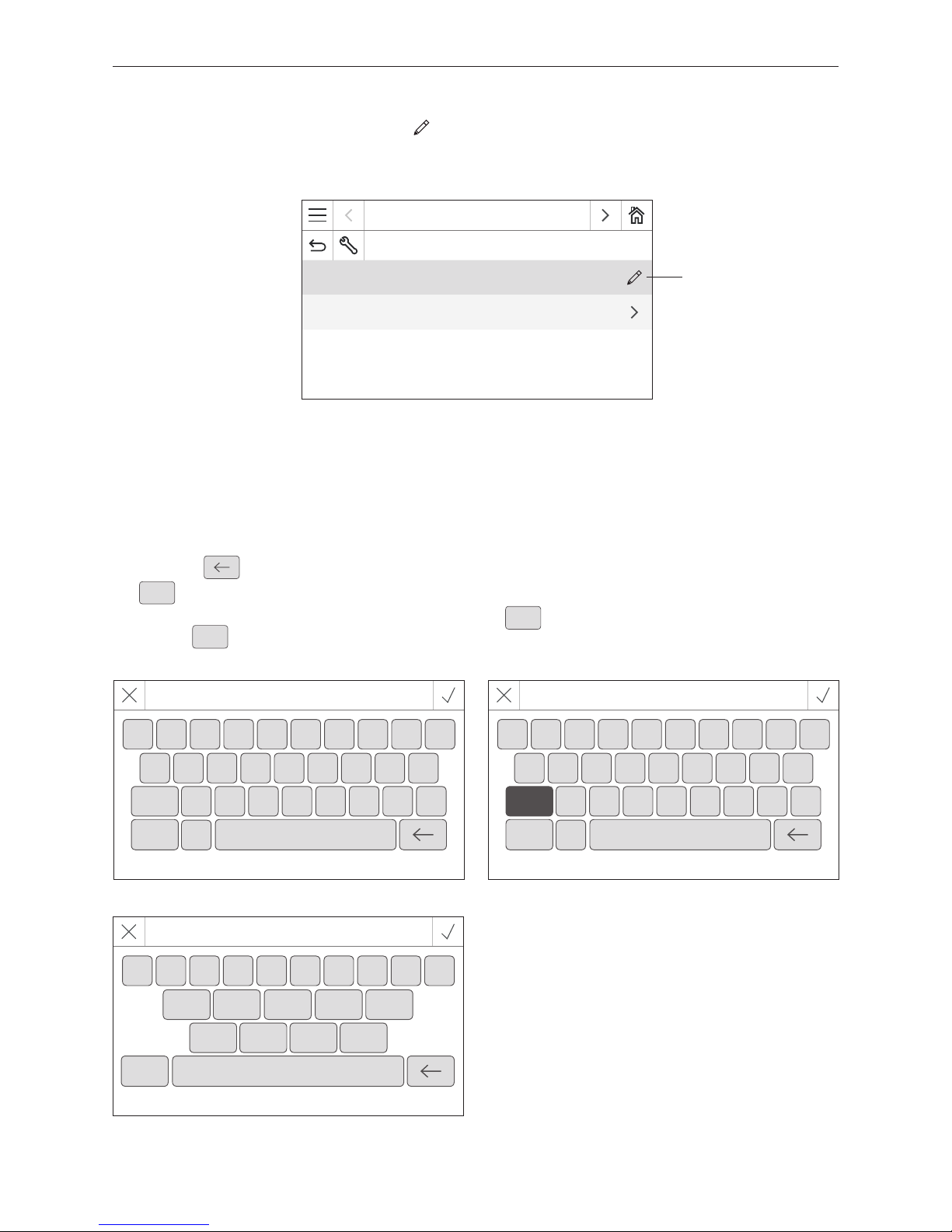
2.6.3 Editing a value and/or selection
A value can always be changed if the editing pen is displayed and pressed – (Fig. 7).
You are then taken to editing mode where the value can be changed and confirmed.
Fig. 7
LogWIN
Operator level
Start-up delay automatic boiler 0 h
Time / Date
Editing pen
2.6.4 On-screen keyboard
Some texts and values are entered using the on-screen keyboard.
When you tap the corresponding letters, the input appears at the top of the display – Fig. 8. You can delete an incorrect
input with the key.
The
Shift
key switches between upper and lower-case letters – Fig. 9.
Numbers and punctuation marks can be entered by tapping the
123+
key – Fig. 10. The letters are displayed again by
pressing the
ABC
key.
Fig. 8 Lower-case letters Fig. 9 Upper-case letters
Fig. 10 Numbers, punctuation marks
LogWIN
Q W E R T Y U I O P
A S D F G H J K L
Shift Z X C V B N M -
123+
.
LogWIN
1 2 3 4 5 6 7 8 9 0
.
,
(
)
=
-
+
*
/
abc
LogWIN
q w e r t y u i o p
a s d f g h j k l
Shift z x c v b n m -
123+
.
Page 13
13
2. InfoWIN Touch display and operating unit
2.7 Turning on for the first time
Setting the language, choosing the boiler and guided start-up
CAUTION
Before turning on for the rst time, the system must be fully wired up electrically, the
DIP switches for the function modules (MES INFINITY control system) must be set
correctly, and the function modules (MES INFINITY control system) and boiler(s) must
be connected to one another – see the installation instructions for the relevant units.
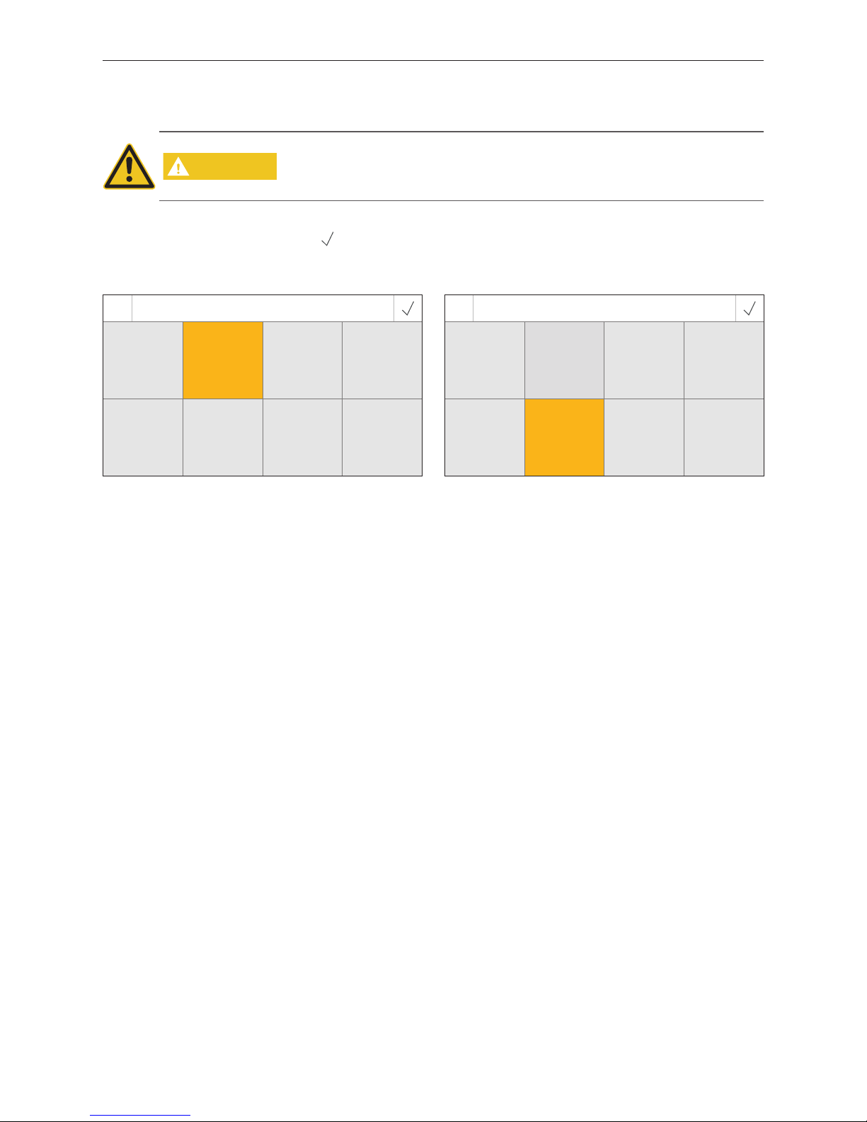
When turning the system on for first time, the language (Fig. 11) and then the boiler (Fig. 12) must be selected. These
displays do not appear again once the
button has been pressed. To change the language and boiler at a later date,
see Section2.9 Basic settings.
Fig. 11 Choosing the language
Language selection
Dansk Deutsch English Español
Français Italiano Polski Slovenščina
Fig. 12 Choosing the boiler
Choose boiler
Pellets Wood Combi boiler Wood chips
Heating oil No MB 1 MB 2
Choose boiler
Setting determining which boiler the InfoWIN Touch controls, e.g. wood chips, wood or pellet boiler, etc.
Factory setting: No, the setting must be selected when the boiler is turned on for the first time.
Selection: Pellets: BioWIN 2
Wood: LogWIN
Combi boiler: DuoWIN
Wood chips: PuroWIN
Heating oil: No function
No: No boiler, e.g. for MultiWIN
PLUS
, simply master operation for remote switching or
web server
MB1: Master control 1 (without boiler)
MB2: Master control 2 (without boiler)
Page 14
14
2. InfoWIN Touch display and operating unit
Fig. 13 Startscreen
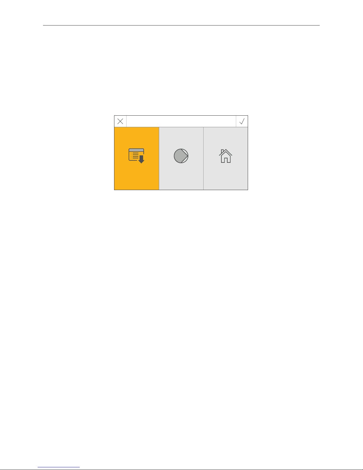
After the language and the boiler have been selected, the startscreen is displayed.
3 selection options are available on the startscreen:
– Guided start-up (Section 2.9.9) for extraordinary circumstances where the unit is not started up by a trained techni-
cian1:
set the time and date, pre-configure the system, test the actuators, then it switches to the boiler homescreen.
– Actuator test (Section 8.3):
Different actuators can be turned on or off.
– Homescreen (Section 2.8):
The system switches directly to the homescreen of the boiler without any settings.
Startscreen
Guided
start up
Actuator test Homescreen
1
Not covered by the guarantee
Page 15
15
2. InfoWIN Touch display and operating unit
2.8 Homescreen (title screen)
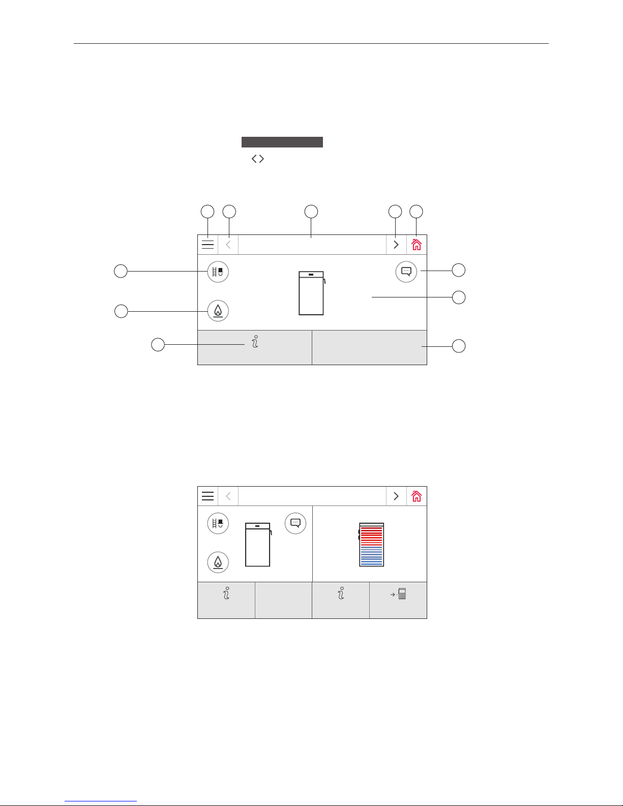
Each boiler and each function module or heating circuit has its own homescreen (title screen). When the system is
turned on, the boiler homescreen is always displayed. This can be displayed as fullscreen (Fig. 14) or splitscreen
(Fig. 15). In splitscreen mode, the homescreen for the buffer load function module is also displayed if this is available.
A splitscreen with other function modules or heating circuits is not possible.
For fullscreen or splitscreen settings, see
Basic settings
→ "Homescreen" – Section 2.9.
To switch to another homescreen, press the
buttons or "swipe"
.
Fig. 14 Fullscreen with LogWIN homescreen
LogWIN
75 °C
Modulation mode
Information level
Fig. 15 Splitscreen with LogWIN and buer load function module homescreen
1 2 23 4
7
8
6
1 ........... Menu button
2 ........... Next button
3 ........... Function title
4 .......... Home button
5 ........... Display of info, error and alarm messages
2
6 .......... Boiler temperature
7 ........... Operating mode and phase
8 .......... Info button
9 .......... Ignition button
1
10 ........ Chimney sweeper button
LogWIN
75 °C
50 %
Modulation
mode
Information
level
Information
level
Loading
10
9
5
1
Only for LogWIN with automatic ignition (accessories)
2
Only if there is an entry in the message list
Page 16
16
2. InfoWIN Touch display and operating unit
2.9 InfoWIN Touch or master control Touch basic settings
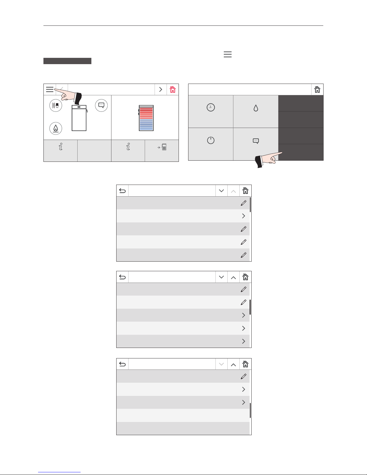
You can switch to the basic settings by initially pressing the menu button on the homescreen (Fig. 16) and then
Basic settings
(Fig. 17).
Fig. 16 Homescreen (shown as splitscreen) Fig. 17
Mo 05.10.2015 / 08:00
Chimney sweeper
Heating programs DHW program
Actuator test
Operator level
Boiler ON/OFF Messages
Basic settings
The following points can be set in the basic settings:
Fig. 18
Basic settings
Language de_DE
Time / Date
Temperature format °C
Unit of weight t, kg
Display brightness 4
Fig. 19
Basic settings
Homescreen
Fullscreen
Boiler
Wood
Function titles
Guided start up
LAN
Fig. 20
Basic settings
MB enabled
Read system
Restart
Factory settings
Device information
LogWIN
75 °C
50 %
Modulation
mode
Information
level
Information
level
Loading
Page 17
17
2. InfoWIN Touch display and operating unit
2.9.1 Language
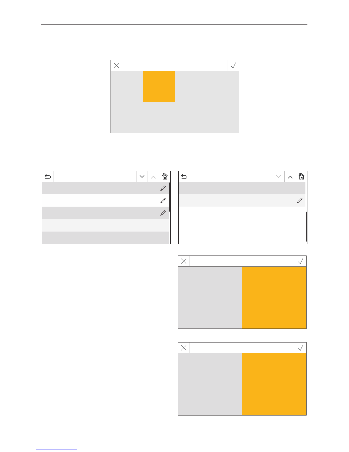
The InfoWIN Touch and master control Touch can show the display texts in several languages. In this sub-menu, you can
choose the language required.
2.9.2 Time/date
In Time / Date, you can select the format, whether the time / date should be synchronised with a timeserver on the
Internet and whether the InfoWIN Touch time / date should be sent.
Fig. 21
Language selection
Dansk Deutsch English Español
Français Italiano Polski Slovenščina
2.9.2.1 Time format
The time is displayed in the chosen format: (e.g. 14:12 or 02.12
PM).
Factory setting: 24 h
Selection: 24 h or 12 h
2.9.2.2 Date format
The date is displayed in the chosen format: (e.g. We17.02.2010
or We 02/17/2010).
Factory setting: TT.MM.JJJJ
Selection: MM/TT/JJJJ
TT.MM.JJJJ
Fig. 22
Time / Date
Time format 24h
Date format DD.MM.YYYY
Timeserver europe.pool.ntp.org
Time zone Europe/Paris
Time 14:16
Fig. 23
Time / Date
Date We 02.09.2015
Sending interval time/date 1 min
Fig. 24
Set time format
12h 24h
Fig. 25
Set date format
MM/TT/JJJJ TT.MM.JJJJ
Page 18
18
2. InfoWIN Touch display and operating unit
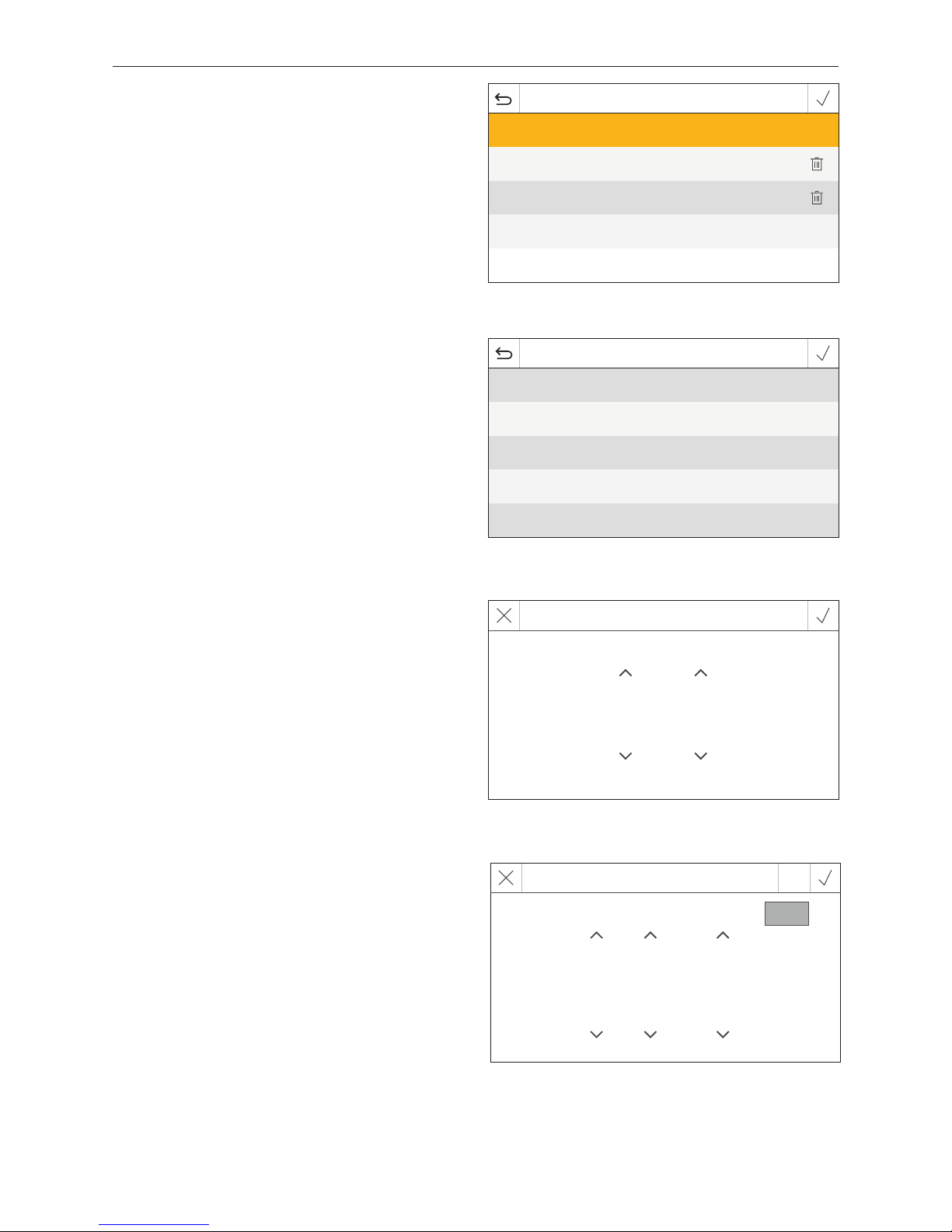
2.9.2.3 Timeserver
The timeserver allows you to select the server for synchronising the time/date or to choose to set these manually.
A maximum of four timeservers can be entered.
Factory setting: disabled
Selection: europa.pool.ntp.org
ch.pool.ntp.org
Add timeserver
Fig. 26
2.9.2.5 Time
The time can only be set if the timeserver is disabled.
2.9.2.6 Date
The date can only be set if the timeserver is disabled.
Choose timeserver
disabled
europe.pool.ntp.org
ch.pool.ntp.org
Add timeserver
+
2.9.2.4 Time zone
The time zone can be set on the here.
Factory setting: Europe/Paris
Selection: All time zones in the world
Fig. 27
Choose time zone
Africa/Cairo
America/Anchorage
America/Caracas
America/Chicago
America/Denver
Fig. 28
Set time
16 : 19
Fig. 29
Set date
3 . 9 . 2015
Today
Page 19
19
2. InfoWIN Touch display and operating unit
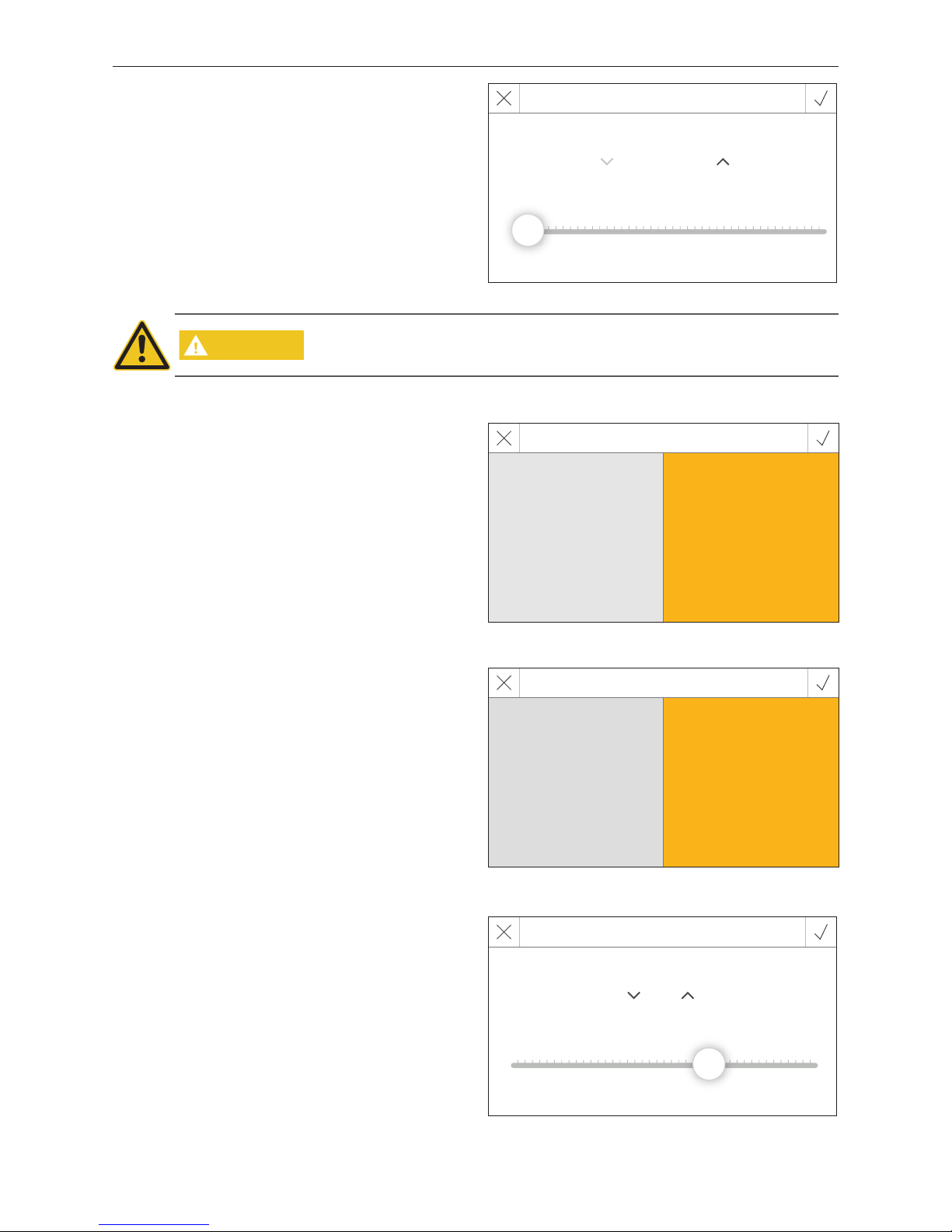
2.9.2.7 Sending interval time/date
This is used to set the interval for sending the time/date of
the InfoWIN Touch or master control Touch to other function modules (e.g. heating circuit function module, etc.). If
0 is set, no data is sent.
Factory setting: 0 min
Setting range: 0–30 min.
Fig. 30
LON-Sending interval
0 min
0 min 30 min
CAUTION
Only one web server Touch, InfoWIN Touch, function module or master control Touch
can send data in a system. The other linked function modules can receive and use the
data or a function module uses the local data.
Fig. 31
2.9.3 Temperature format
All temperatures are displayed in the chosen format (e.g.
30.6 °C or 87.0 °F).
Factory setting: °C
Selection: °C or °F
Set temperature format
°F °C
2.9.4 Unit of weight
The weight is displayed in the chosen format (e.g. 6.5kg
or 14.3 lbs).
Factory setting: t, kg
Selection: t, kg or tn. sh., lbs
Fig. 32
Choose unit of weight
tn. sh., lbs t, kg
2.9.5 Display brightness
The display brightness can be changed.
Factory setting: 4
Setting range: 1–6
Fig. 33
Set display brightness
4
1 6
Page 20
20
2. InfoWIN Touch display and operating unit
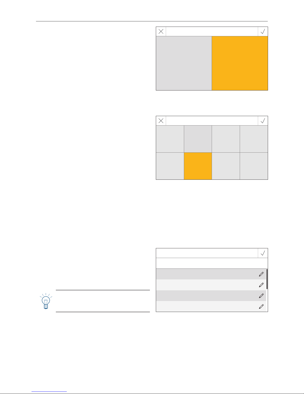
2.9.6 Homescreen
The homescreen can be displayed as fullscreen or
splitscreen (e.g. boiler and buffer load function module
simultaneously).
Factory setting: Fullscreen
Selection: Fullscreen
Splitscreen with buffer
Fig. 34
Configure homescreen
Splitscreen with buffer Fullscreen
2.9.7 Boiler
Setting determining which boiler the InfoWIN Touch controls, e.g. wood chips, wood or pellet boiler, etc.
Factory setting: No, the setting must be selected when the
boiler is turned on for the first time.
Selection:
Pellets: BioWIN 2
Wood: LogWIN
Combi boiler: DuoWIN
Wood chips: PuroWIN
Heating oil: No function
No: No boiler, e.g. for MultiWIN
PLUS
, simply master operation for remote switching or web
server
MB1: Master control 1 (without boiler)
MB2: Master control 2 (without boiler)
Fig. 35
Choose boiler
Pellets Wood Combi boiler Wood chips
Heating oil No MB 1 MB 2
2.9.8 Function titles
With function titles, the designations (e.g. LogWIN) of the
boiler or the function module (e.g. heating circuit 1) can
be changed.
Fig. 36
Function titles
By changing a restart is required.
Boiler LogWIN
Buffer tank 3000 l
Heating circuit
HEATING CIR-
CUIT 1
Heating circuit
HEATING CIR-
CUIT 2
Note!
After changing a function title, the system
must be read again – see Section 2.9.12.
Page 21
21
2. InfoWIN Touch display and operating unit
Fig. 38
2.9.10 LAN
Setting determining whether a LAN connection should be
established.
Factory setting: disabled
Selection: enabled/disabled
If enabled, the following can be set:
– DYN IP
– VPN
– Alarm
– Alarm URL
– MAC-address
– DHCP
– IPV4
– Subnet
– Gateway
– DNS
Fig. 39
LAN settings
LAN enabled
LAN status VPN/Internet connection
LAN settings
LAN settings
DYN IP disabled
VPN enabled
Alarm enabled
Alarm URL httpa://connect-api.wi...ager/api/v1/alarms
MAC-address 00:23:43:00:40:3a
Fig. 40
LAN settings
DHCP enabled
IPV4 192.168.0.108.
Subnet 255.255.255.0.
Gateway 192.168.0.254.
DNS 213.33.99.70.80.120.17.70.
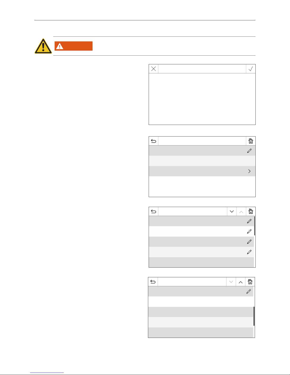
2.9.9 Guided start-up
WARNING
This assistant is used to provide support when turning the heating system on for the
first time without trained service personnel. It does not substitute professional commissioning and is not covered by the guarantee.
Fig. 37
Guided start up
This assistant is to support the first start up. It does
not substitute a professional
commissioning!
Page 22
22
2. InfoWIN Touch display and operating unit
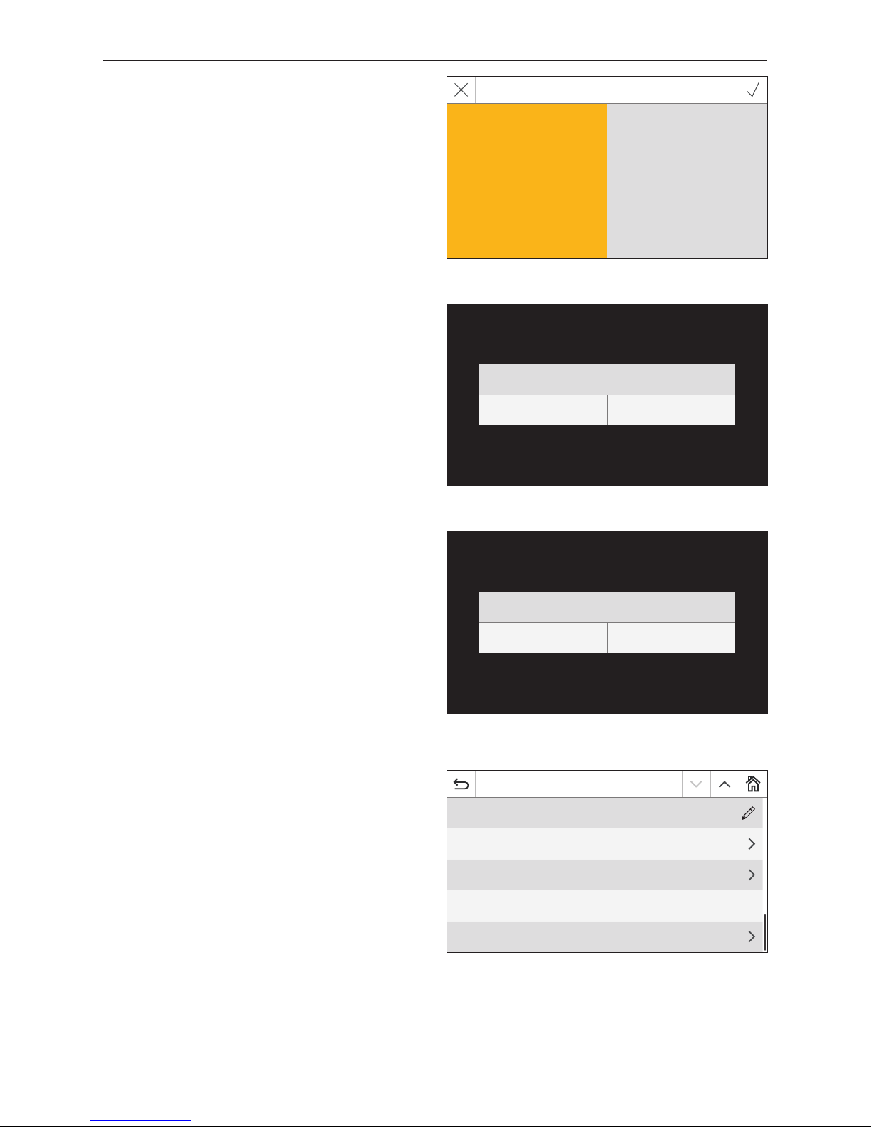
2.9.11 MB (master control)
Setting determining whether the other function modules
should be displayed next to the boiler.
Factory setting: enabled
Selection: enabled/disabled
Fig. 41
MB
disabled enabled
2.9.12 Read system
The entire system with boiler and function modules is read
in again.
Fig. 42
Read system new
Read Cancel
2.9.13 Restart
The InfoWIN Touch or master control Touch is restarted.
Fig. 43
2.9.14 Factory settings
No function at present.
Restart device
Restart Cancel
Fig. 44
Basic settings
MB enabled
Read system
Restart
Factory settings
Device information
Page 23
23
2. InfoWIN Touch display and operating unit
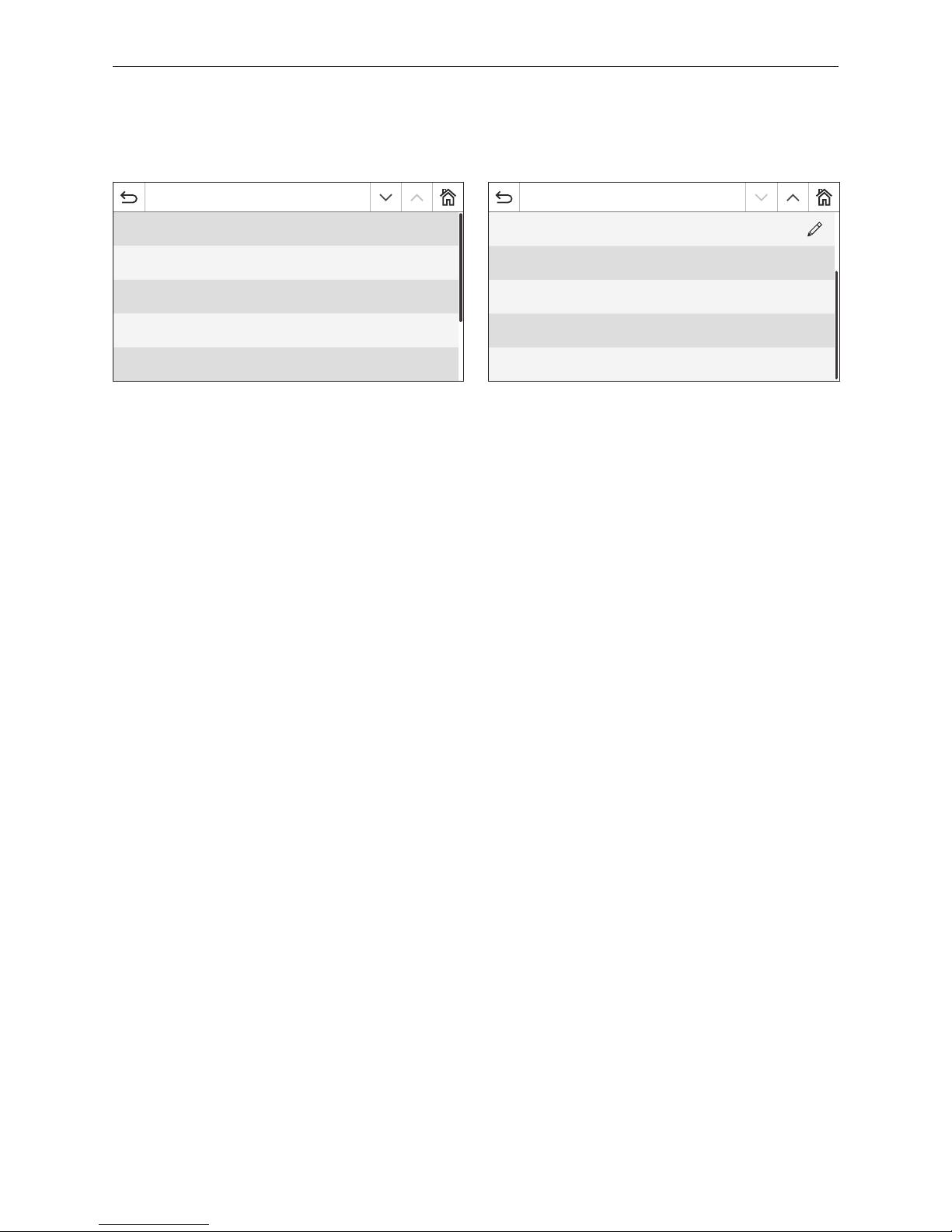
2.9.15 Device information
The current software version, serial numbers or check numbers is displayed.
Fig. 45
Basic settings
Software version display module v1.0.0
Firmware version 1.0
MAC-address 12:34:56:67:90:ac:
Serial number 001009160201425611
Test number 123456e
Basic settings
Scan systems on restart
Fig. 46
Page 24
24
3. Operation modes
Boiler Off
Turn off Cancel
Mo 05.10.2015 / 08:00
Chimney sweeper
Heating programs DHW program
Actuator test
Operator level
Boiler ON/OFF Messages
Basic settings
LogWIN
75 °C
Modulation mode
Information level
3. Operation modes
The various operating modes are displayed on InfoWIN Touch together with the corresponding operating phases.
3.1 OFF mode
Turning the boiler off
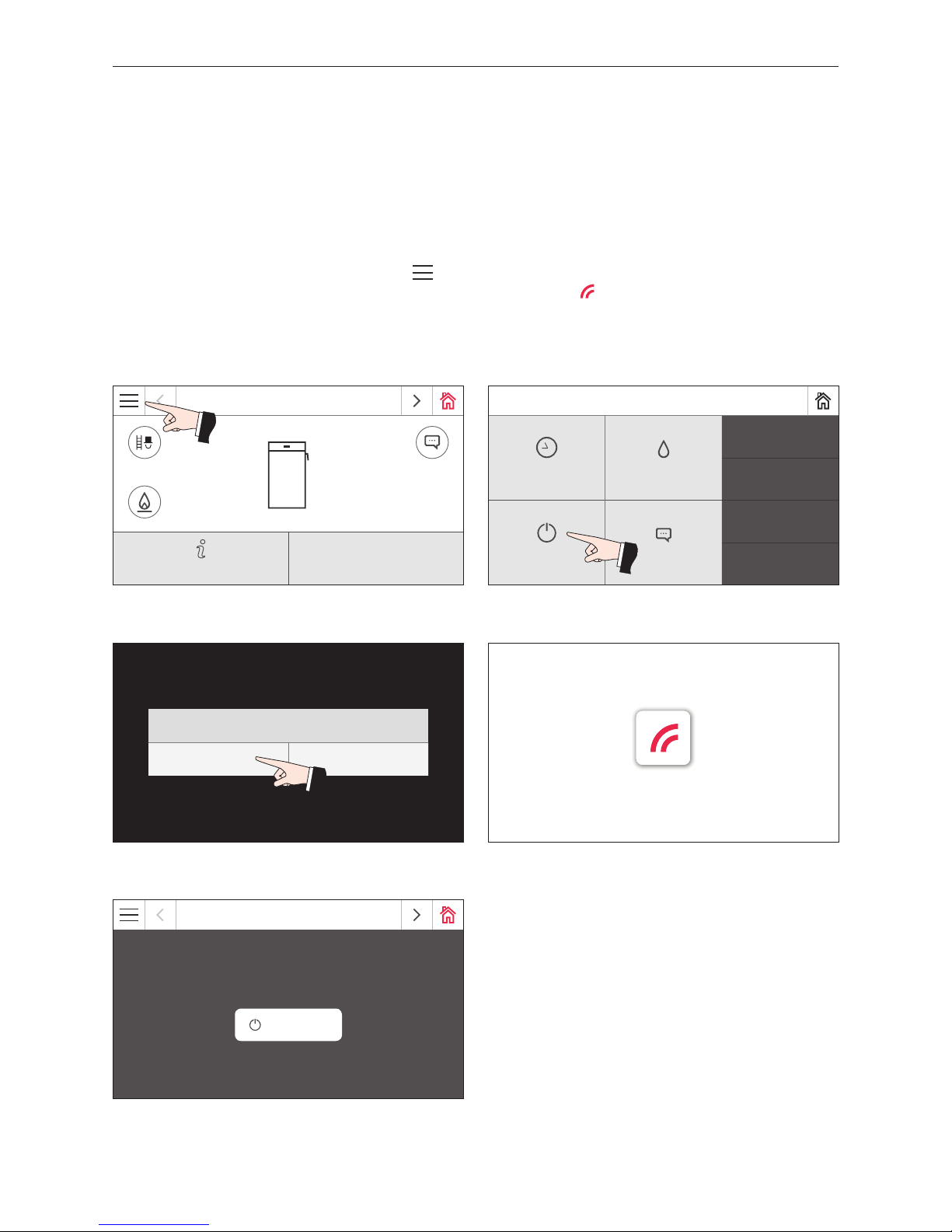
On the homescreen, first press the menu button (Fig. 47), then "Boiler ON/OFF" (Fig. 48) and then confirm "Boiler
Off" – Fig. 49. When turning off, the turning off screen is displayed initially (Fig. 50), following by "Boiler is turned
off" – Fig. 51.
In OFF mode, the boiler and the InfoWIN Touch display turn off and only the LED is lit up green. The display turns back
on again when the InfoWIN Touch is touched.
Fig. 47 Homescreen Fig. 48 Main menu
Fig. 49 Turning the boiler o Fig. 50 Boiler is turned o
Fig. 51 Boiler is turned o
LogWIN
Boiler is turned off
Turn on
Page 25
25
3. Operation modes
3.2 ON mode, self-test, display OFF
Turning the boiler on
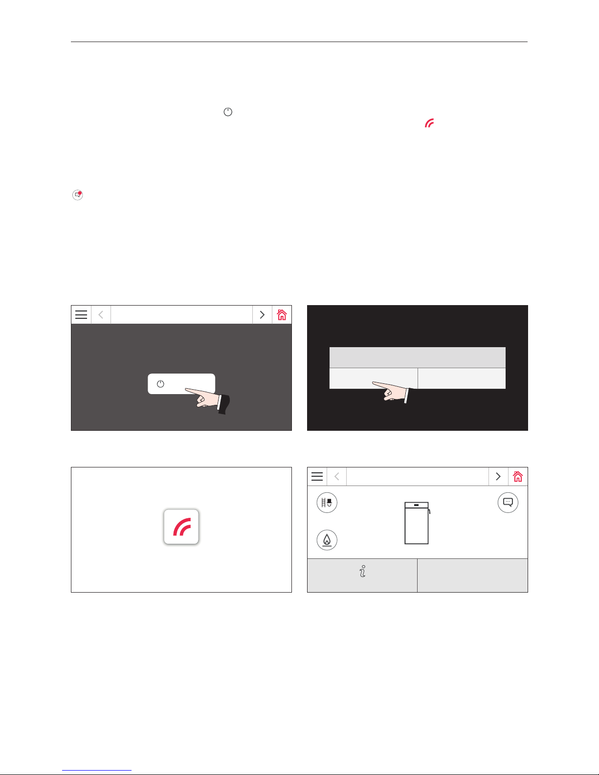
Touch the InfoWIN Touch, the press the turn on button (Fig. 52) and confirm "Boiler On" – Fig. 53. The system is identified during the power-up procedure. The self-test starts automatically and the load screen is displayed – Fig. 54.
Self-test
Some sensors, switches and motors are checked during the self-test.
After a successful self-test, the homescreen (Fig. 55) is displayed. If an error is found during the self-test, a message
1
is displayed (see Section7).
Display OFF
If the InfoWIN Touch is not touched for more than 12 min., the display goes dark and only the LED is lit up green. The
display turns back on again when the InfoWIN Touch is touched.
Fig. 52 Turning the boiler on Fig. 53 Conrming Boiler On
Fig. 54 Load screen
Fig. 55 Homescreen
LogWIN
Boiler is turned off
Turn on
Boiler On
Turn on Cancel
LogWIN
20 °C
Stand-by
Information level
Page 26
26
3. Operation modes
3.3 Chimney sweeper
This function aids the performance of legally required emissions testing.
Note!
The chimney sweeper function can only be started in the modulation mode or step-loading operating phases.
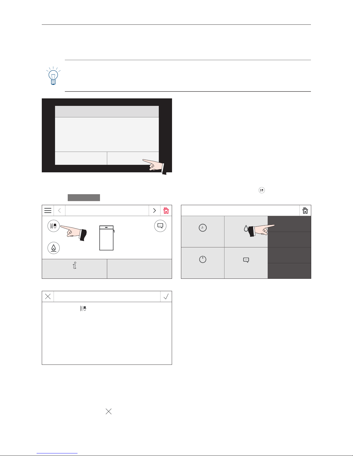
In all other operating phases, the information "This function is not possible in this opera phase!" (Fig. 56) is
displayed when the chimney sweeper button is pressed and the function is not started.
The boiler temperature is regulated to approx. 70°C for 45 min. on an MES INFINITY or MES
PLUS
control system. After
the lighting timer has counted down (12min.), the display goes dark but the function remains unchanged. The first time
that you press the display, only the display is turned on.
The chimney sweeper function ends:
– When the Cancel button
is pressed.
– Automatically after 45 min.
Press on the InfoWIN Touch briefly to turn the display on. Press the chimney sweeper button
on the homescreen
(Fig. 57) or
Chimney sweeper
in the menu to start the chimney sweeper function – Fig. 58.
Fig. 56
Information
This function is not possible in this opera phase!
Cancel
Fig. 57 Homescreen Fig. 58 Menu
Fig. 59
LogWIN
75 °C
Modulation mode
Information level
Mo 05.10.2015 / 08:00
Chimney sweeper
Heating programs DHW program
Actuator test
Operator level
Boiler ON/OFF Messages
Basic settings
Chimney sweeper func
Modulation mode
Boiler temperature
65 °C
Page 27
27
4. Operating phases
4. Operating phases
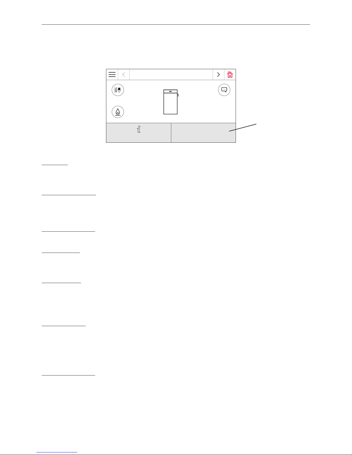
The relevant operating phase is displayed on the boiler homescreen – Fig. 60.
Stand-by
The boiler is ready for starting (see LogWIN operating manual).
After 12 min., the display goes dark; only the green LED is lit up.
Stand-by off period
The automatic boiler is locked out.
Pressing the Cancel button cancels the "Stand-by off period" operating phase and switches to the operating phase to
"Stand-by".
Cladding door open
If the cladding door is opened, "Cladding door open" is displayed for as long as it remains open.
Ignition ready
1
The boiler is prepared for automatic ignition mode.
Pressing the Cancel button cancels the "Ignition ready" operating phase and switches to the operating phase to "Stand-by".
Ignition phase
1
The boiler is in automatic ignition mode. Once the ignition phase is complete, the system switches to the "Start procedure" operating phase.
Pressing the Cancel button cancels the "Ignition phase" operating phase; the blower runs for a further 2 minutes before
switching to the "Stand-by" operating phase.
Start procedure
The start procedure is started automatically once the ignition phase1 is complete or the cladding door is closed. Once
the "Start procedure" operating phase is complete (at least 30 min.), the system switches into the "Modulation mode"
operating phase.
The start procedure is cancelled by pressing the Cancel button or automatically after around 15 min. if the combustion
chamber temperature is not increasing sufficiently. The system them switches into the stand-by operating phase.
Flame stabilisation
Once combustion has been interrupted, an attempt is made to build constant combustion back up and the system then
changes into the "Modulation mode" or "Stand-by" operating mode.
Fig. 60 Homescreen
Operating phase display
1
Only for LogWIN with automatic ignition (accessories).
LogWIN
75 °C
Modulation mode
Information level
Page 28

28
4. Operating phases
Modulation mode
The boiler is in the "Modulation mode" operating phase, i.e. in normal heating mode. The boiler output is controlled in
a continuously variable manner.
Step-loading
If the "Step-loading" function is set, the system automatically changes to the "Step-loading" operating phase once the
step-loading conditions are met.
Blower OFF
If the boiler temperature exceeds 87 °C (90 °C), the blower switches off and only switches on again when the boiler temperature drops below the set "restart temperature" (65–75 °C) or automatically after 2 hours. The system then switches
to the "Flame stabilisation" operating phase.
Burnout
The boiler enters burnout at the end of combustion. The blower continues to run until the combustion chamber has
cooled down. The blower then turns off and the system switches to the "Stand-by" operating phase.
Page 29
29
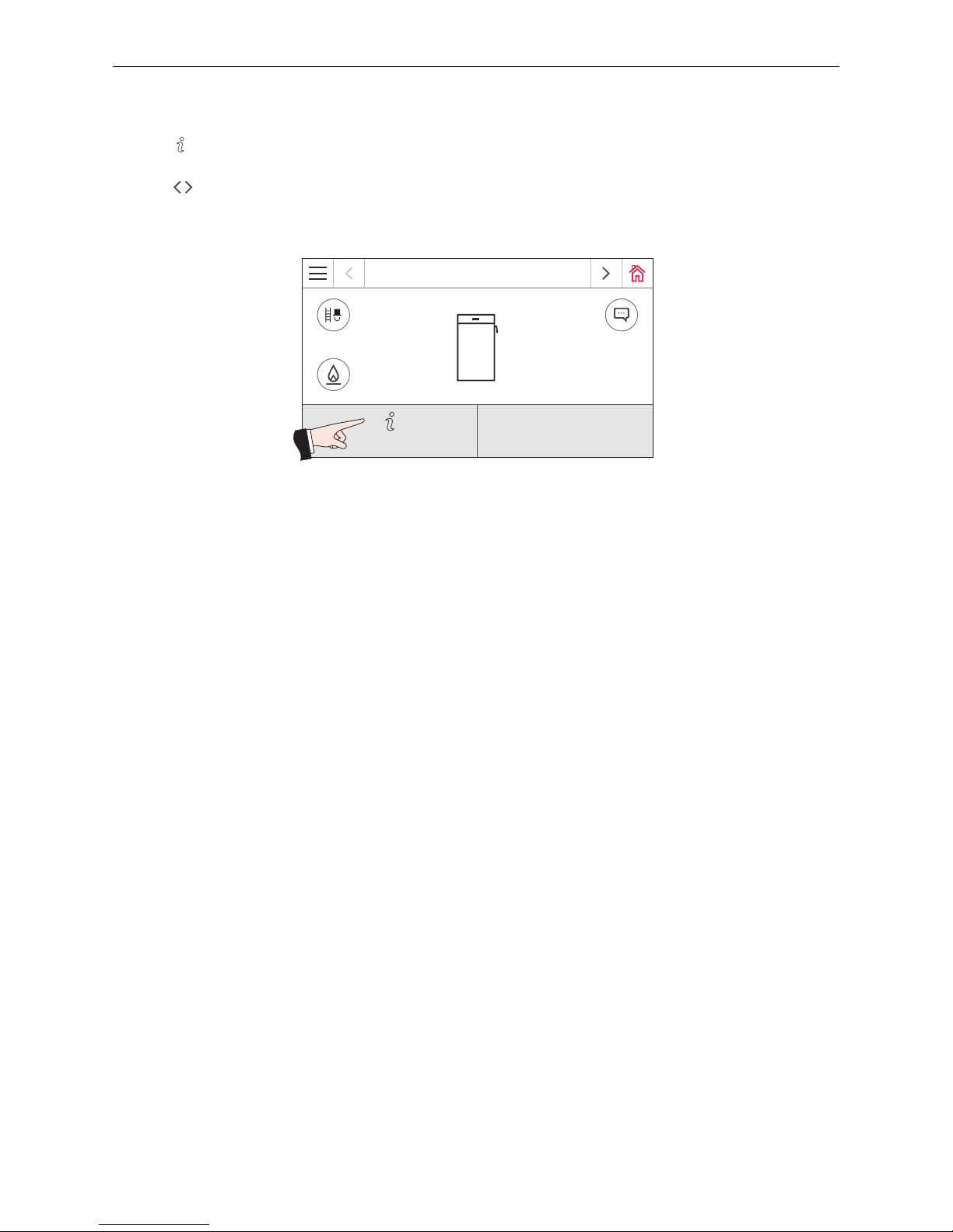
5. Information level
Fig. 61 Homescreen
LogWIN
75 °C
Modulation mode
Information level
5. Information level
Press the to switch to the information level. You can call up the most important boiler information here – Fig. 61.
Each heating circuit, boiler and function module has its own information level. To switch to another information level,
press the
buttons or "swipe"
.
The following information can be called up at the information level:
– Top buffer temperature
– Centre buffer temperature
– Bottom buffer temperature
– Charge status
– Combustion chamber temperature
– Flue gas temperature
– Operating hours
– Number of starts
– Software version
– Boiler model
Page 30

30
5. Information level
Top, centre, bottom buffer temperatures
The buffer temperatures are shown only in combination with a buffer tank and the MES
PLUS
WVF+ module with sensors
connected the for top, centre and bottom respectively.
Charge status
The charge status shows the usable energy of the buffer in percentage steps.
The charge status is calculated continuously based on the buffer temperatures (top, centre, bottom) and the highest
heating circuit or hot water set point.
Combustion chamber temperature
The current temperature in the boiler's combustion chamber is displayed.
Flue gas temperature
The current flue gas temperature is displayed.
Note!
The flue gas temperature is measured directly on the flue outlet. It may therefore deviate from a standard
measurement.
Operating hours
The total number of boiler operation hours is displayed.
Number of starts
The number of starts is displayed.
Software version
The current software version of the firing automates (main PCB) is displayed.
Boiler model
The boiler model of the LogWIN is displayed.
Page 31
31
6. Operator level
6. Operator level
Each heating circuit, boiler and function module has its own operator level. The information and settings at operator
level are accessible to everyone.
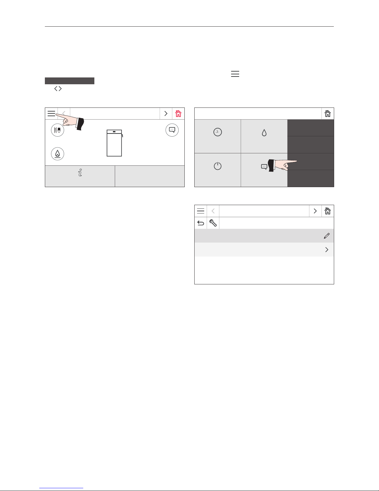
You can switch to the operator level by initially pressing the menu button
on the homescreen (Fig. 62) and then
Operator level
(Fig. 63). Switch between the different operator levels for the boiler and the function modules with
the buttons or by "swiping".
Fig. 62 Homescreen Fig. 63
Fig. 64 Operator level
LogWIN
75 °C
Modulation mode
Information level
Mo 05.10.2015 / 08:00
Chimney sweeper
Heating programs DHW program
Actuator test
Operator level
Boiler ON/OFF Messages
Basic settings
LogWIN
Operator level
Start-up delay automatic boiler 0 h
Time / Date
Page 32
32
6. Operator level
6.1 Start-up delay automatic boiler
With the start-up delay on the automatic boiler, you can set a period during which the automatic boiler remains locked
after the end of the burnout of the solid fuel boiler. The set time is saved.
Factory setting: 0 h
Setting range: 0–24 h
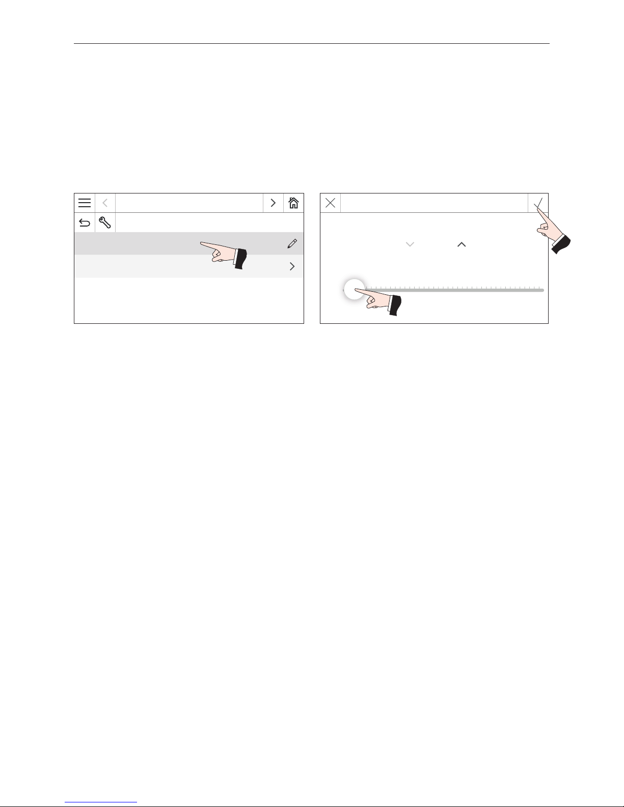
Set the required start-up delay with the slider and confirm – Fig. 66.
Fig. 65 LogWIN operator level Fig. 66
LogWIN
Operator level
Start-up delay automatic boiler 0 h
Time / Date
Start-up delay automatic boiler
0 h
0 h 24 h
Page 33
33
6. Operator level
LogWIN
Operator level
Start-up delay automatic boiler 0 h
Time / Date
6.2 Time/date
The time or the date must only be set here when the "Sending interval time/date" is set to 0 min in the basic settings
in Section 2.9.2.7. Otherwise, the time or date set here is overwritten.
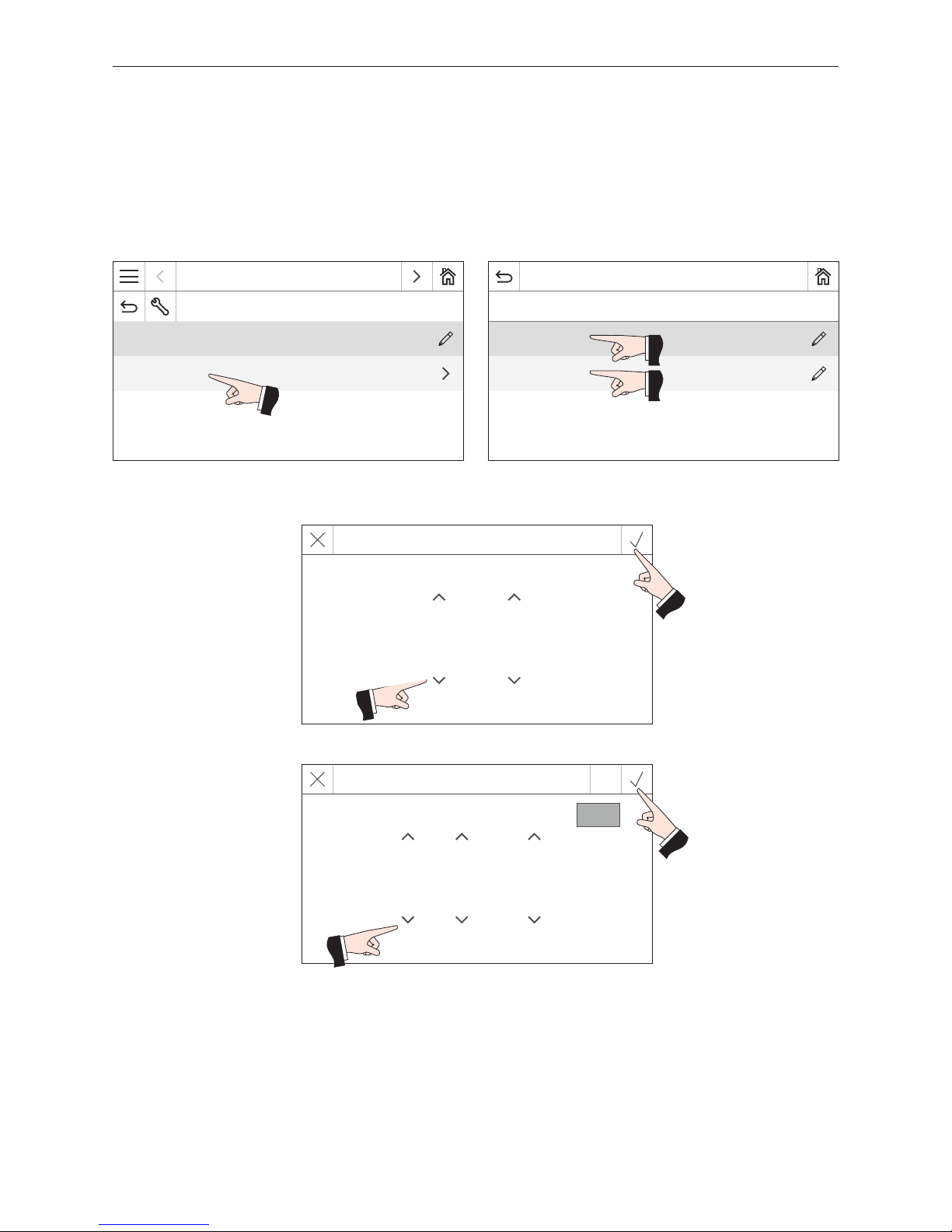
This time or date is used for the time control of the automatic ignition (accessories). Select the time or date (Fig. 68).
Set the time or date and confirm – Fig. 69, Fig. 70.
Fig. 67 LogWIN operator level Fig. 68 Selecting the time or date
LogWIN
Time / Date
Time 11:36
Date 20.11.2015
Fig. 69 Setting the time and conrming
Set time
16 : 19
Fig. 70 Setting the date and conrming
Set date
3 . 3 . 2016
Today
Page 34
34
7. Troubleshooting
7. Troubleshooting
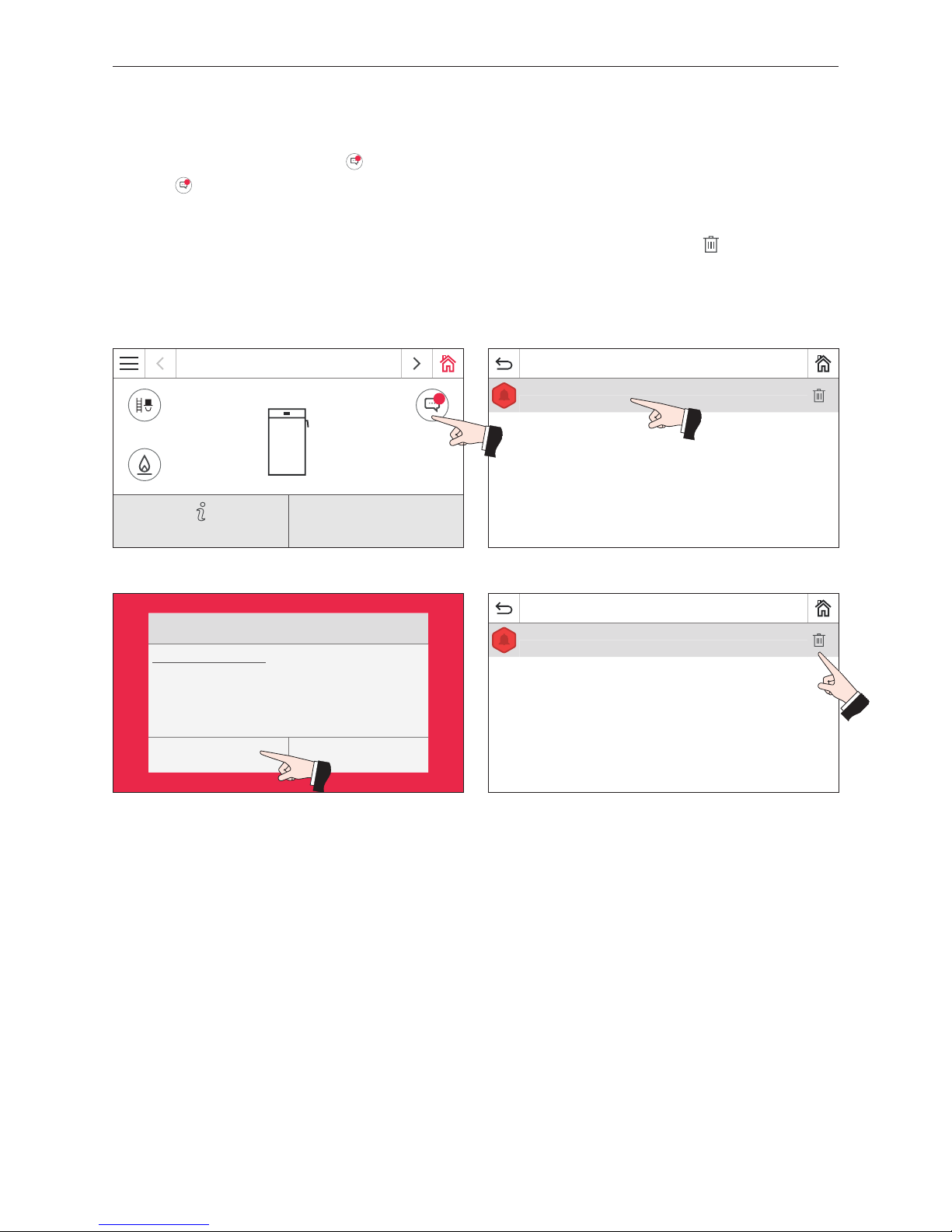
The boiler is self-monitoring during operation. All deviations from normal operation are displayed on the InfoWIN Touch
or master control Touch by messages 1.
Press the
1
button (Fig. 71) to display all available messages in a list – Fig. 72. Press the message directly to display
the corresponding info text – Fig. 72.
For nearly all messages, the system must be reset after the problem has been rectified. In these cases, "Reset" is
displayed – Fig. 73. When the problem has been rectified, the message can be deleted with the
button – Fig. 74.
If "Reset" is not displayed, the boiler starts operating again automatically after the problem has been rectified.
Fig. 71 Fig. 72
Fig. 73 Fig. 74
If you wish to call Windhager Customer Service or your customer service partner due to a malfunction, please first make
a note of the following data from the rating plate:
– Type
– Factory number
– Year of manufacture
– Error or alarm message
Messages
Boiler sensor defective
LogWIN, alarm 076 Tu 08.09.2015 / 09:06
Alarm 076
Boiler sensor defective
Check boiler sensor and connections.
LogWIN / Tu 08.09.2015 / 09:06
Reset Cancel
Messages
Boiler sensor defective
LogWIN, alarm 076 Tu 08.09.2015 / 09:06
LogWIN
1
75 °C
Modulation mode
Information level
Page 35
35
7. Troubleshooting
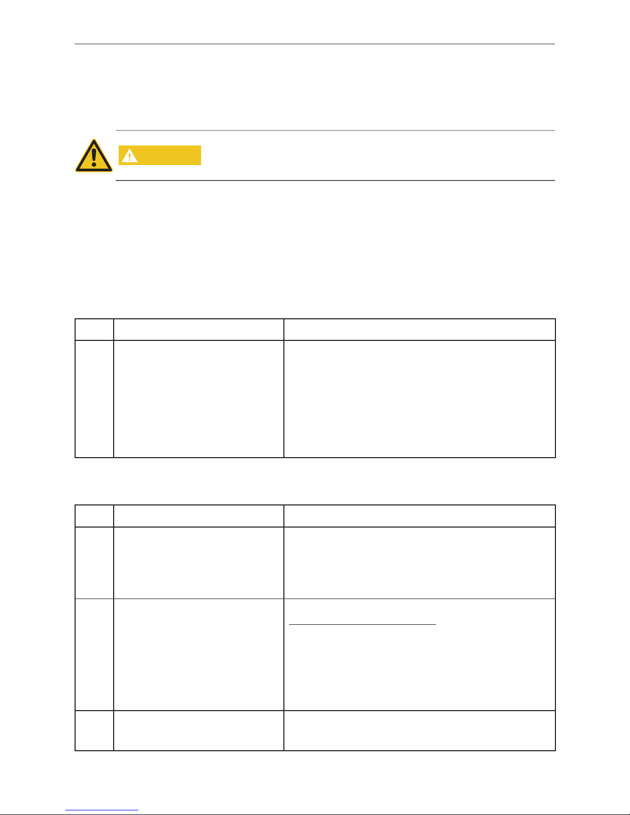
7.3 No display on InfoWIN Touch
Code Display on InfoWIN Touch Cause/remedy
–
No display,
LED not lit up
Boiler is off, cannot be turned on.
a) No electricity, check the cable to the device and the building fuse.
b) No electricity, device fuse blown – check and replace if necessary – see
Fig. 75.
c) Power plug loose or poorly or not connected together during installation –
check and connect together firmly if necessary
d) InfoWIN
Touch
plug loose or poorly or not connected together during installation – check and connect together firmly if necessary, plug is located behind
the right side panel cladding – see LogWIN installation instructions; Installing the cladding.
e) Inform Windhager Customer Service or a heating technician.
7.4 Error messages
Code Display on InfoWIN Touch Cause/remedy
Error
226
No flame during ignition
Ignition failure.
a) No fuel in front of ignition opening. Start procedure not performed according
to the instructions. "Reset" or delete message.
b) Ignition opening in lighting door or on vertical grate covered with ash, clean
(see LogWIN Premium Touch operating manual). Press the Reset button.
c) Ignition element is defective, inform Windhager Customer Service or a
heating technician.
Error
268
Cladding door switch defective
Verify cladding door sensor!
Let the boiler burn out, the error must be rectified.
After burning out (stand-by operating phase):
Open the cladding door – blower must be running.
Close cladding door and press "Shut down start" – blower must stop. If this
doesn't happen:
a) Check and adjust shifting travel of cladding door switch (audible click) – see
LogWIN installation instructions.
b) Cladding door switch defective, inform Windhager Customer Service or a
heating technician.
Error
281
Flue gas temperature sensor defective
Verify flue gas temperature sensor
and connections.
It is not possible to display the flue gas temperature. No effect on operation.
Replace the flue gas temperature sensor, inform Windhager Customer Service or
a heating technician.
7.1 Thermal discharge safeguard
If the thermal discharge safeguard is dripping, clean the seals and the valve seat. Replace the piston and the seal if
necessary – see the enclosed list of spare parts.
Note: There is no need to remove the fitting for this purpose.
CAUTION
The function of the thermal discharge safeguard must be checked once a year by a
technician and the thermal safety device must be checked for limescale – see installation instructions. If there is limescale in the thermal safety device then it must always
be removed.
7.2 LED bar
In the event of an error or alarm message, the LED bar on the front of the operating panel flashes.
Alarm 1 to 199: Red
Error 200 to 399: Orange
Page 36
36
7. Troubleshooting
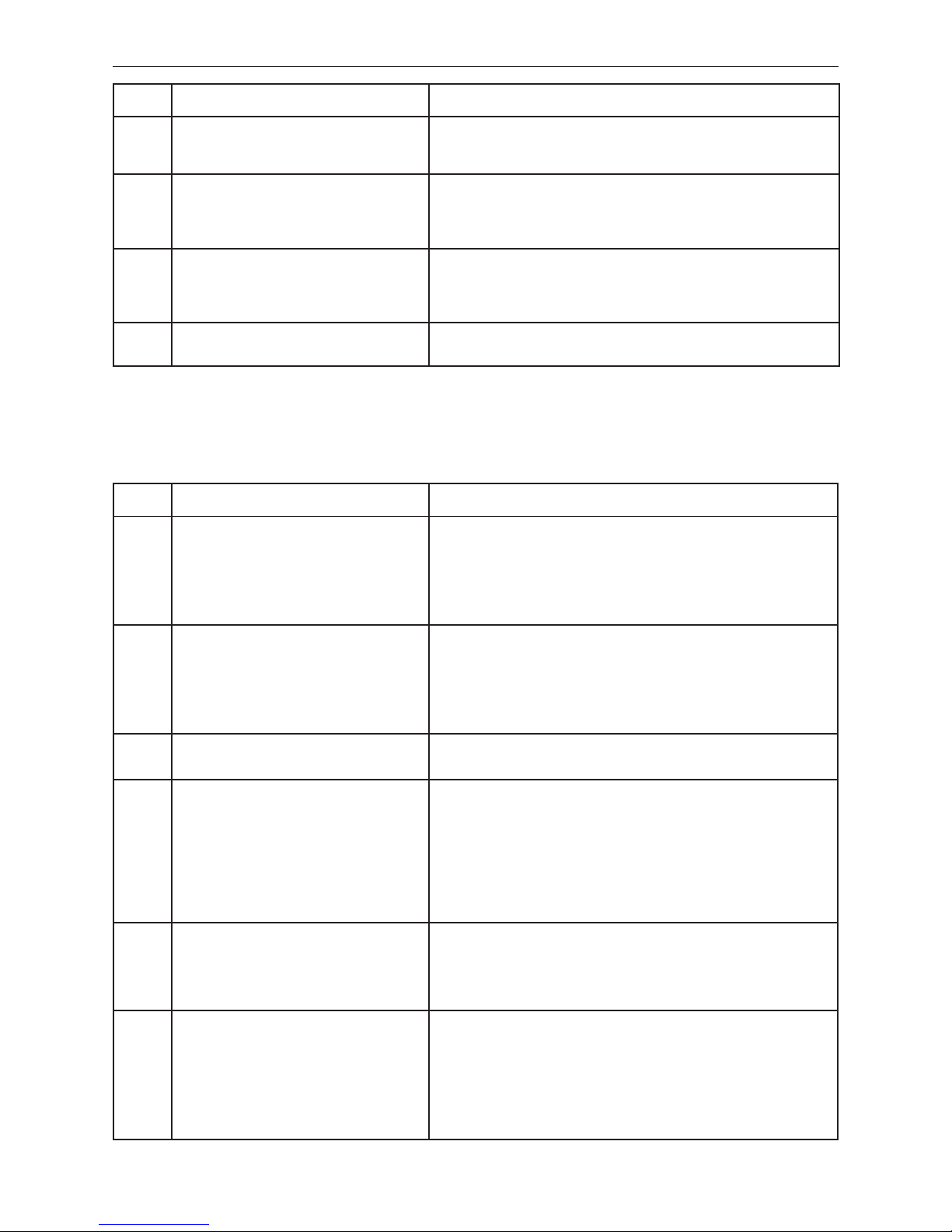
Code Display on InfoWIN Touch Cause/remedy
Error
372
Starting report
Too low combustion temperature during heat
up.
Start procedure performed with damp and/or poor quality wood. Start procedure
not performed according to the instructions. "Reset" or delete message.
Error
373
Starting report
Too low heating demand at start.
Ensure enough heat is consumed (open manual mixing valve, set control system to
heating requirement/heating mode). "Reset" or delete message.
Important: If the control system is not demanding any heat (reducing demand)
and the hot water tank or buffer tank is up to temperature – do not start!
Error
375
Heating up at excessively high
boiler temperature
Ensure enough heat is consumed (open manual mixing valve, set control system to
heating requirement/heating mode). "Reset" or delete message.
Important: If the control system is not demanding any heat (reducing demand)
and the hot water tank or buffer tank is up to temperature – do not start!
Error
396
Cladding door open
Close cladding door.
Close cladding door.
7.5 Alarm messages
Code Display on InfoWIN Touch Cause/remedy
Alarm
001
Primary airflap defect
Primary airflap blocked or defect.
The primary airflap is no longer reaching its position. Primary airflap motor or
end switch defective.
"Reset" or delete message. If the fault reoccurs, inform Windhager Customer Service or a heating technician.
Replace the primary airflap motor or end switch, inform Windhager Customer
Service or a heating technician.
Alarm
003
Secondary airflap defect
Secondary airflap blocked or defect.
The secondary airflap is no longer reaching its position. Secondary airflap motor
or end switch defective.
"Reset" or delete message. If the fault reoccurs, inform Windhager Customer Service or a heating technician.
Replace the secondary airflap motor or end switch, inform Windhager Customer
Service or a heating technician.
Alarm
015
230V not reached
Verify 230VAC power supply.
There is no 230 V mains voltage for the firing automates.
Inform Windhager Customer Service or a heating technician.
Alarm
016
Induced draught blower defective
Clean blower wheel and clean blower box.
The actual speed is different from the set speed. The boiler switches to burnout
mode.
a) The blower wheel and blower box are dirty; clean them (see LogWIN Premium
Touch operating manual). "Reset" or delete message.
b) Blower plug loose or not snapped in, firmly connect plug (on rear panel of
boiler).
c) Replace the induced draught blower motor, inform Windhager Customer Ser-
vice or a heating technician.
Alarm
076
Boiler sensor defective
Check boiler sensor and connections.
a) "Reset" or delete message. If the fault recurs immediately after a short pe-
riod, or recurs at regular intervals, contact Windhager Customer Service or
your heating technician.
b) Replace the boiler sensor, inform Windhager Customer Service or a heating
technician.
Alarm
078
Thermocontrol sensor defective
Check thermocontrol sensor and connections.
The boiler switches to burnout mode.
a) Thermocontrol sensor is too cold (below 0 °C). Warm up sensor.
b) "Reset" or delete message. If the fault recurs immediately after a short pe-
riod, or recurs at regular intervals, contact Windhager Customer Service or
your heating technician.
b) Replace the thermocontrol sensor, inform Windhager Customer Service or a
heating technician.
Page 37
37
7. Troubleshooting
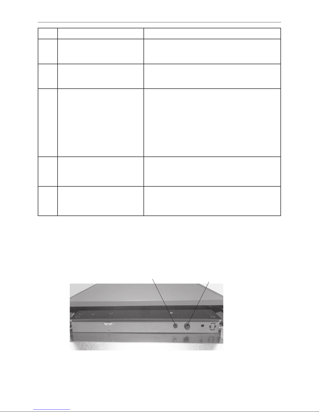
Fig. 75 LogWIN operating panel with cover removed at the rear – rear view
F1 fuse T 6.3 A
Cover, under which is the release button for the
safety temperature limiter
Code Display on InfoWIN Touch Cause/remedy
Alarm
088
O2 probe defective
Check O2 probe and connections.
a) "Reset" or delete message. If this fault occurs again, contact Windhager Cus-
tomer Service or a heating technician.
b) Replace the O
2
probe, inform Windhager Customer Service or a heating tech-
nician.
Alarm
089
O2 probe (heating) defective
Check O2 probe, transformer and connections.
a) "Reset" or delete message. If this fault occurs again, contact Windhager Cus-
tomer Service or a heating technician.
b) Replace the O
2
probe and/or transformer, inform Windhager Customer Ser-
vice or a heating technician.
Alarm
144
Safety device has tripped
Check safety devices.
Safety temperature limiter or external safety equipment has tripped.
a) Check the water level or pressure in the heating system – re-ll, bleed the air.
b) Air in the heating system – bleed air.
c) The heat pump or boiler feed pump is sticking or is defective – start pump
manually or have it repaired.
d) Check external safety equipment (e.g. low-water cut-off, etc.).
Once the boiler water temperature falls below 90 °C, take the rear of the cover, remove the cover, press the release button of the safety temperature limiter
firmly – Fig. 75.
If this fault occurs again, contact Windhager Customer Service or a heating technician.
Alarm
187
No communication with
firing automate
Check linkage of firing automate and connections.
a) Check the connection cable or plug connection between the InfoWIN Touch
and the firing automate; "Reset" or delete message. Inform Windhager Customer Service or a heating technician.
b) Connect the firing automate. "Reset" or delete message. Inform Windhager
Customer Service or a heating technician.
Alarm
189
Unable to communicate
with additional print
Check link to additional print, firing device
and connections.
a) Check the connection cable or plug connection between the InfoWIN, ad-
ditional print and the firing automate; "Reset" or delete message. Inform
Windhager Customer Service or a heating technician.
b) Connect the additional print, firing automate. "Reset" or delete message.
Inform Windhager Customer Service or a heating technician.
Page 38
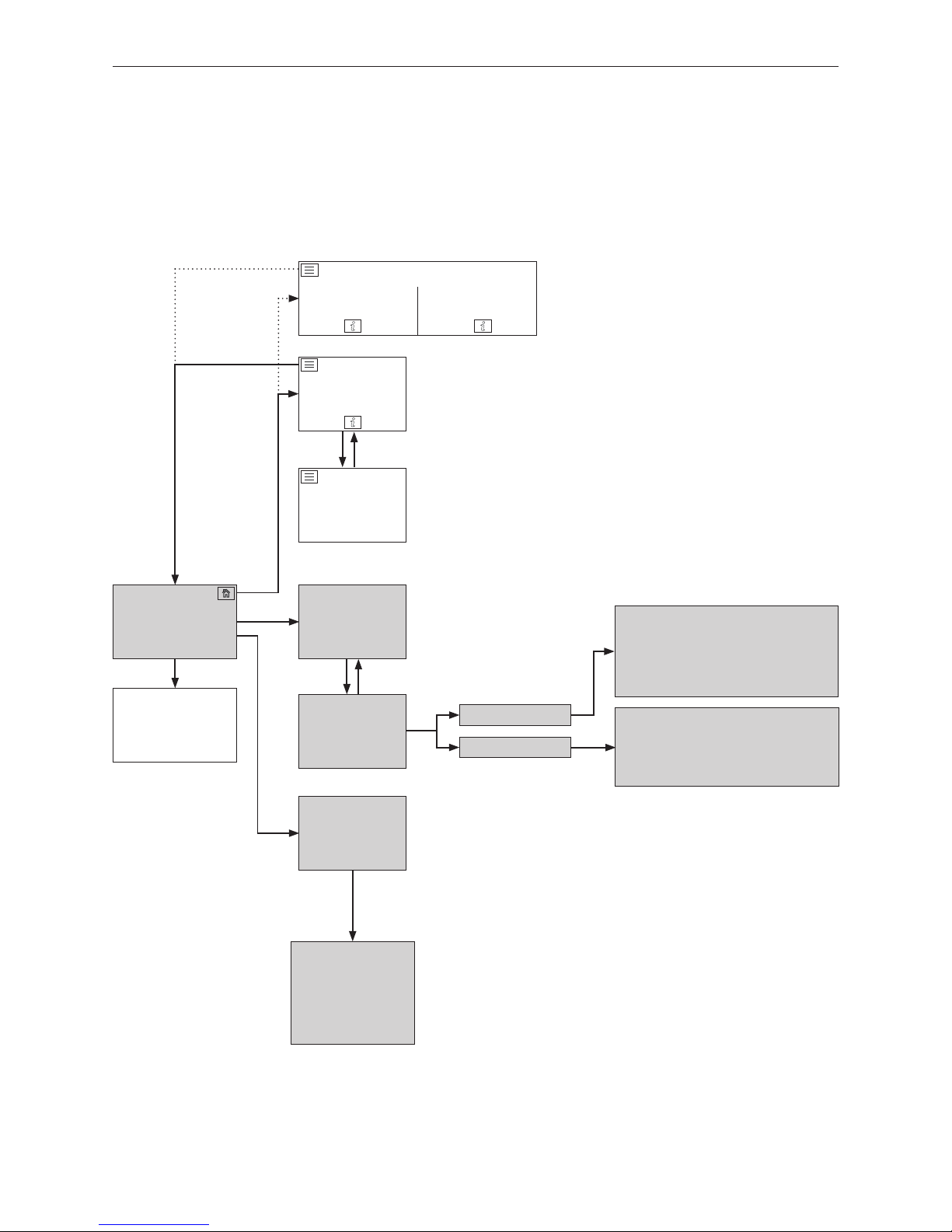
38
8. For the service technician/heating technician
Menu
Homescreen
boiler
Basic settings
(see Section 2.9)
Information level
boiler
(see Section 5)
Operator level
boiler
(see Section 6)
Service level
boiler
(see Section 8.2)
Actuator test
boiler
(see Section 8.3)
Split homescreen
1
Boiler Buffer load
Boiler temperature for restart
Automatic ignition
Burnout
LED brightness
Induced draught blower
Primary airflap
Secondary airflap
O2 heating
Automatic ignition
Measurement values
Parameters
Induced draught blower set speed
Pos. Prim. airfl.
Pos. Sec. airfl.
O2 signal
O2 heat current
8. For the service technician/heating technician
8.1 LogWIN menu structure for service level and actuator
test
1
In the basic settings, it is possible to set whether the homescreen should be displayed as fullscreen or splitscreen, see Section 2.9.6.
Page 39
39
8. For the service technician/heating technician
Information
Service level only for trained service personnel!
5
OK Cancel
Mo 05.10.2015 / 08:00
Chimney sweeper
Heating programs DHW program
Actuator test
Operator level
Boiler ON/OFF Messages
Basic settings
LogWIN
75 °C
Modulation mode
Information level
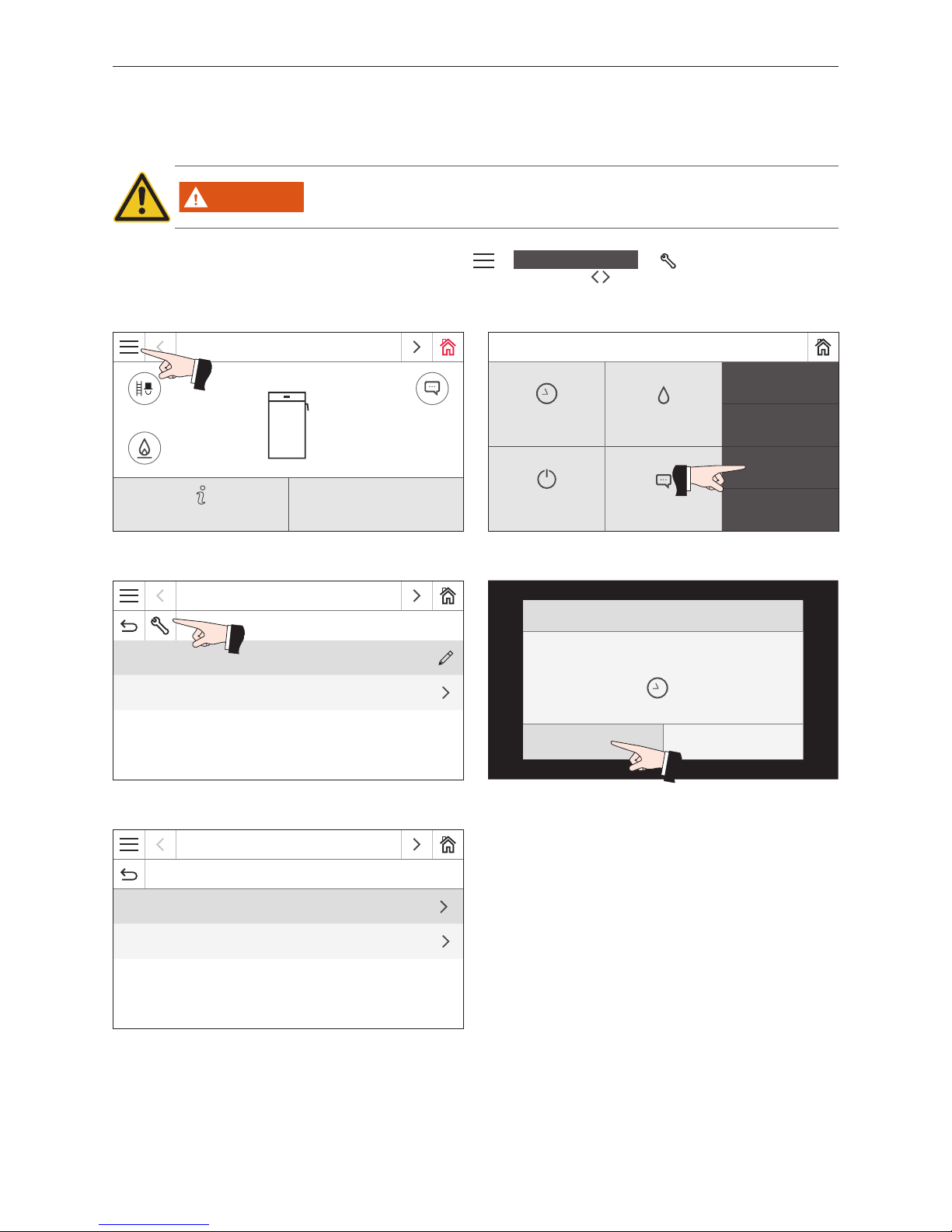
8.2 Service level
Measurement values and parameters can be displayed and modified on the service level.
WARNING
Only trained service personnel may perform system modifications in the service level.
Navigate to the service level by pressing the menu button
→
Operator level
→ and holding down the OK
button for 5 sec. You can switch between the different service levels with the buttons.
Fig. 76 Homescreen
Fig. 77
Fig. 78 Fig. 79
LogWIN
Operator level
Start-up delay automatic boiler 0 h
Time / Date
Fig. 80
LogWIN
Service level
Measurement values
Parameters
Pressing for 5 sec.
Page 40

40
8. For the service technician/heating technician
8.2.1 Measurement values
The following measurement values are displayed:
Induced draught blower set speed
The nominal speed of the blower is displayed in rpm.
Pos. Prim. airfl.
The position of the primary airflap is displayed in %.
Pos. Sec. airfl.
The position of the secondary airflap is displayed in %.
O2 signal
The O2 signal of the lambda sensor is displayed in %.
O2 heat current
The O2 heat current of the lambda sensor is displayed in A.
8.2.2 Parameters
Menu items in parameters
– Boiler temperature for restart
– Automatic ignition
– Burnout
– LED brightness
Boiler temperature for restart
The blower turns off if the boiler temperature is too high. The restart temperature is the temperature at which the blower turns back on and the boiler resumes normal heating mode.
Factory setting: 75 °C
Possible settings: 65 – 75 °C
Automatic ignition
This adjuster is used to set whether automatic ignition is present or not.
Factory setting: depending on condition on delivery
Burnout
– Automatic detection
The burnout characteristics are determined by the buffer load/switching function module or the MES
PLUS
WVF+ mod-
ule.
If the select mode is set to "Solid fuel operation" on the buffer load/switching function module or MES
PLUS
WVF+
module, then "Burnout" with ember quantity is undertaken. With all other settings, a normal burnout is undertaken.
– Normal
A normal burnout is always undertaken, i.e. the wood is burnt as best as possible until no more remains without
ember quantity.
– Ember quantity
Burnout with ember quantity is always undertaken, i.e. basic embers are maintained to make it easier to start up
again.
LED brightness
LED bar brightness setting on the left of the operating panel next to the InfoWIN Touch.
Page 41
41
8. For the service technician/heating technician
Actuator test
LogWIN Heating circuit 1
Heating circuit 2 Buffer load/switching
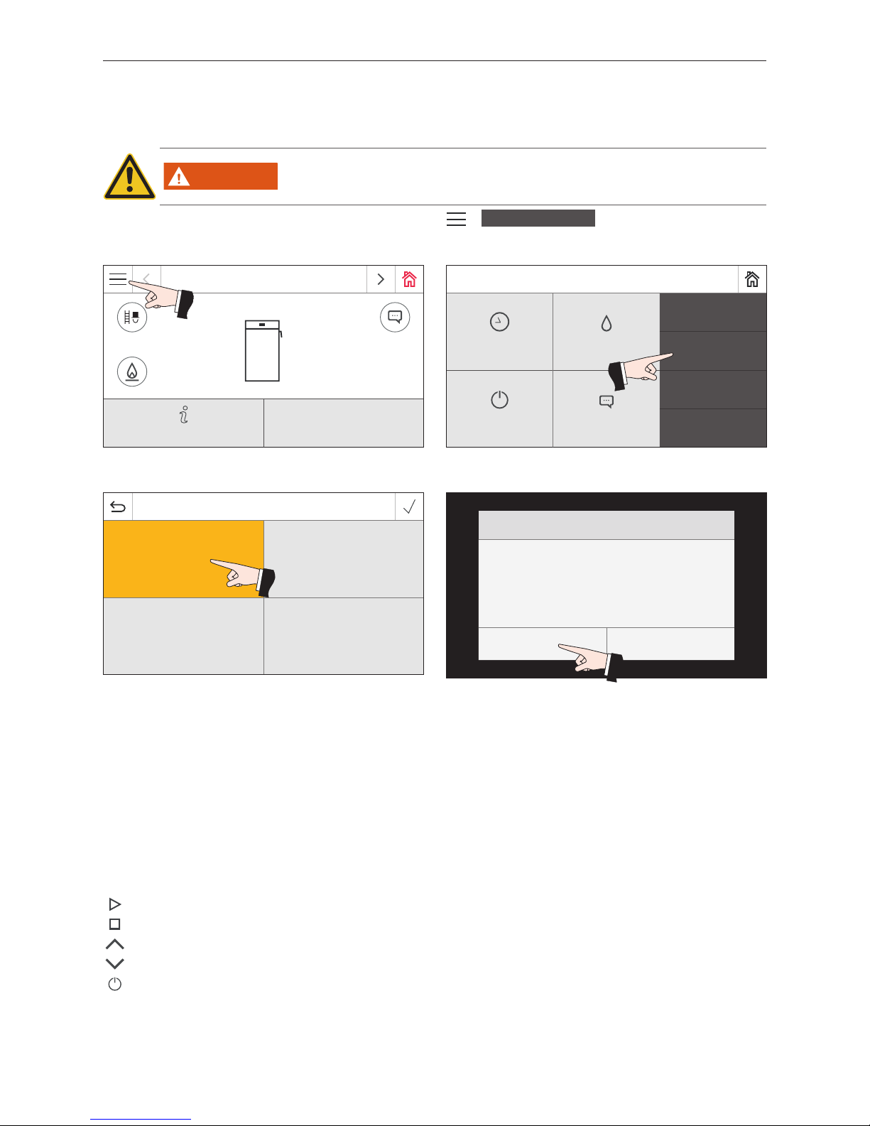
8.3 Actuator test
In the actuator test, different actuators can be tested.
WARNING
Only trained service personnel may perform the actuator test.
Navigate to the actuator test by pressing the menu button
→
Actuator test
. The installed and connected
function modules or the boiler to be selected are displayed.
The following actuators can be started with LogWIN.
– Induced draught blower
– Primary airflap
– Secondary airflap
– O2 heating
– Ignition
The actuators are turned off again automatically after a timeout without actuations. A self-test is started at the end of
an actuator test.
When this icon is pressed, the following actions are performed:
Actuator ON
Actuator OFF
Actuator OPEN
Actuator CLOSED
Actuator release
Mo 05.10.2015 / 08:00
Chimney sweeper
Heating programs DHW program
Actuator test
Operator level
Boiler ON/OFF Messages
Basic settings
LogWIN
75 °C
Modulation mode
Information level
Fig. 81 Homescreen
Fig. 82
Fig. 83 Fig. 84
Information
Boiler in operation! Do you want to start the actu-
ator test? This can take 20 min.
Operating phase: Burnout
OK Cancel
Page 42

42
8. For the service technician/heating technician
8.4 Starting up the integrated web server
8.4.1 Internet connection and router configuration
An Internet connection is needed for communication. The Internet router must assign the InfoWIN Touch a local IP
address. This requires a DHCP server (standard function of router). If the firewall settings prevent a connection being
established with the "WindhagerConnect" Windhager portal server, they must be changed accordingly. No other settings
are needed. Please observe the operating manual for your Internet router.
8.4.2 Start-up
1. The InfoWIN Touch must be de-energised (interrupt supply voltage).
2. Use a LAN cable to connect the Internet router to the InfoWIN Touch.
3. Connect the 4-pole LON plug to the InfoWIN Touch.
Once the voltage supply has been connected to the InfoWIN Touch, the Windhager logo and a charge bar appear on
the device after a short delay. When turning on for the first time, the language must then be selected (see Section 2.7).
Otherwise, the homescreen is displayed straight away and the LED lights up green. The status of the connection to
Windhager Connect, etc., can then be checked and set under "Basic settings > LAN" (Section 2.9).
Your system is now ready and you can operate and control your heating system with the Windhager app "myComfort".
8.4.3 Reserved IP address ranges
The internal web server uses the following IP address ranges for internal communication and/or to establish a connection with the database: 10.254.253.xxx; 10.8.xxx.xxx and 10.9.xxx.xxx.
These IP address ranges must not be used by the router and/or in the LAN network.
Page 43

Page 44
EN 303-5
Baumuster geprüft
Produktion überwacht
Type tested
Production monitored
windhager.com
IMPRESSUM
Media owner, issuer and publisher: Windhager Zentralheizung GmbH, AntonWindhager-Straße 20, 5201 Seekirchen am Wallersee, Austria, T +43 6212 2341 0, F +43
6212 4228, [email protected], Images: Windhager; subject to amendments, printing
and layout errors. Translatet from 024298/02 - AWP-vor
AUSTRIA
Windhager Zentralheizung GmbH
Anton-Windhager-Strasse 20
A-5201 Seekirchen near Salzburg
T +43 6212 2341 0
F +43 6212 4228
Windhager Zentralheizung GmbH
Carlbergergasse 39
A-1230 Vienna
GERMANY
Windhager Zentralheizung GmbH
Deutzring 2
D-86405 Meitingen near Augsburg
T +49 8271 8056 0
F +49 8271 8056 30
Windhager Zentralheizung GmbH
Gewerbepark 18
D-49143 Bissendorf
SWITZERLAND
Windhager Zentralheizung Schweiz AG
Industriestrasse 13
CH-6203 Sempach-Station near Lucerne
T +41 4146 9469 0
F +41 4146 9469 9
Windhager Zentralheizung Schweiz AG
Rue des Champs Lovats 23
CH-1400 Yverdon-les-Bains
Windhager Zentralheizung Schweiz AG
Dorfplatz 2
CH-3114 Wichtrach
ITALY
Windhager Italy S.R.L.
Via Vital 98c
I-31015 Conegliano (TV)
T +39 0438 1799080
UNITED KINGDOM
Windhager UK Ltd
Tormarton Road
Marshfield
South Gloucestershire, SN14 8SR
T +44 1225 8922 11
The warranty conditions require that the boiler and related accesso-
ries be properly installed and started up by Windhager Customer Service or the customer service partner; otherwise the manufacturer's
warranty will not be honoured.
Malfunctions resulting from improper operation or adjustment as well
as use of poor-quality fuel types or fuel types that are not recommen-
ded are not covered by the warranty. Further, the warranty shall be
void if equipment other than that provided by Windhager is installed.
The special warranty conditions for your system are available in the
"Warranty conditions" sheet supplied with your boiler.
Start-up and regular maintenance following the terms of the "War-
ranty conditions" will assure safe, environmentally friendly and eco-
nomical operation of your system. We recommend that you obtain a
maintenance agreement.
WARRANTY CONDITIONS
 Loading...