

Windhager LogWIN Klassik Assembly Instructions
WOOD
Assembly instructions
LogWIN Klassik
½ m wood gasification boiler
For small and large houses
Nominal thermal output: 18, 25, 30 kW
10/2013 093391/01
Version 1 – 22nd January 2015
USER MANUAL FOR BATCH FED INDEPENDENT WOOD LOG FIRED BOILERS
SUPPLEMENTARY INSTALLATION INSTRUCTIONS FOR THE UK MARKET
TO BE READ IN CONJUNCTION WITH THOSE IN THE INSTRUCTION BOOKLET
READ THE INSTRUCTION BOOKLET AND THESE SUPPLEMENTARY
INSTRUCTIONS CAREFULLY BEFORE INSTALLATION
These instructions together with those in the instruction booklet cover the basic principles
to ensure the satisfactory installation of the boiler, although detail may need slight
modification to suit particular local site conditions.
In all cases the installation must comply with current Building Regulations, Local Authority
Byelaws and other specifications or regulations as they affect the installation of the boiler.
If any guidance contained within this manual contradicts advice given in the main
manufacturer’s instruction manual then the most stringent advice must apply.
It should be noted that the Building Regulations requirements may be met by adopting the
relevant recommendations given in British Standards BS 8303, BS EN 15287-1:2007 as an
alternative means to achieve an equivalent level of performance to that obtained following
the guidance given in Approved Document J.
Please note that it is a legal requirement under England and Wales Building Regulations
that the installation of the boiler is either carried out under Local Authority Building Control
approval or is installed by a Competent Person registered with a Government approved
Competent Persons Scheme. HETAS Ltd operate such a Scheme and a listing of their
Registered Competent Persons can be found on their website at www.hetas.co.uk.
CO Alarms:Building regulations require that whenever a new or replacement fixed solid fuel or
wood/biomass appliance is installed in a dwelling a carbon monoxide alarm must be fitted
in the same room as the appliance. Further guidance on the installation of the carbon
monoxide alarm is available in BS EN 50292:2002 and from the alarm manufacturer’s
instructions. Provision of an alarm must not be considered a substitute for either installing
the appliance correctly or ensuring regular servicing and maintenance of the appliance and
chimney system.
HEALTH AND SAFETY PRECAUTIONS
Special care must be taken when installing the boiler such that the requirements of the Health and Safety at
Work Act (1974) are met.
Handling
Adequate facilities must be available for loading, unloading and site handling.

Version 1 – 22nd January 2015
Fire Cement
Some types of fire cement are caustic and should not be allowed to come into contact with the skin. In case
of contact wash immediately with plenty of water.
Asbestos
This boiler contains no asbestos. If there is a possibility of disturbing any asbestos in the course of
installation then please seek specialist guidance and use appropriate protective equipment.
Metal Parts
When installing or servicing this boiler care should be taken to avoid the possibility of personal injury.
BOILER PERFORMANCE
Refer to the main instruction manual for details of the boiler’s performance.
PREPARATORY WORK AND SAFETY CHECKS
IMPORTANT WARNING
This boiler must not be installed into a chimney that serves any other heating appliance.
There must not be an extractor fan fitted in the same room as the boiler as this can cause the boiler to emit
fumes into the room.
Chimney
In order for the boiler to perform satisfactorily the chimney height must be sufficient to ensure an adequate
draught of approximately 15 Pa so as to clear the products of combustion and prevent smoke problems into
the room.
NOTE: A chimney height of not less than 4.5 metres measured vertically from the outlet of the boiler to the
top of the chimney should be satisfactory. Alternatively the calculation procedure given in EN 13384-1 may
be used as the basis for deciding whether a particular chimney design will provide sufficient draught.
The outlet from the chimney should be above the roof of the building in accordance with the provisions of
Building Regulations Approved Document J.
Because the boiler runs at high efficiencies, the temperature of the flue gases is at times lower than
conventional solid fuel appliances. Although it is not classed as a condensing appliance, the low flue gas
temperature results in condensation occurring within the flue. Any chimney flue system must therefore be
able to withstand the effects of condensate and operate under wet conditions (designation letter W). In
addition it should be soot fire resistant and able to withstand the corrosive effects of flue products generated
by solid fuels (designation G and 3 respectively). If installation is into an existing masonry chimney then it will
require re-lining with a liner meeting the specification described above. Existing concrete or clay lined
chimneys are not suitable for this boiler and must be lined as described above. All installations must be in
accordance with Building Regulations Approved Document J.
Any existing chimney must be clear of obstruction and have been swept clean immediately before installation
of the lining system. Where the chimney is believed to have previously served an open fire installation it is
possible that the higher flue gas temperature from a closed appliance may loosen deposits that were
previously firmly adhered, with the consequent risk of flue blockage. It is therefore recommended that the
chimney be swept a second time within a month of regular use after installation.

Version 1 – 22nd January 2015
If there is no existing chimney then any new system must be to the designation described above and in
accordance with Building Regulations Approved Document J.
A single wall metal fluepipe is suitable for connecting the boiler to the chimney but is not suitable for use as
the complete chimney. The chimney and connecting fluepipe must have a minimum diameter of 150 mm and
its dimension should be not less than the size of the outlet socket of the boiler.
Any bend in the chimney or connecting fluepipe should not exceed 45. 90 bends should not be used.
Combustible material should not be located where the heat dissipating through the walls of fireplaces or flues
could ignite it. Therefore when installing the boiler in the presence of combustible materials due account
must be taken of the guidance on the separation of combustible material given in Building Regulations
Approved Document J and also in these boiler instructions.
If it is found that there is excessive draught in the chimney then a draught stabiliser should be fitted in the
chimney above the chimney above the flue pipe connection. Fitting of a draught stabiliser will affect the
requirement for the permanent air supply into the room in which the boiler is fitted in accordance with
Approved Document J (see also combustion air supply).
Adequate provision e.g. easily accessible soot door or doors must be provided for sweeping the chimney and
connecting fluepipe.
Hearth
The hearth should be able to accommodate the weight of the boiler and its chimney if the chimney is not
independently supported. The weight of the boiler is indicated in the brochure.
The boiler should preferably be installed on a non-combustible hearth of a size and construction that is in
accordance with the provisions of the current Building Regulations Approved Document J.
The clearance distances to combustible material beneath, surrounding or upon the hearth and walls adjacent
to the hearth should comply with the guidance on the separation of combustible material given in Building
Regulations Approved Document J and also in these boiler instructions.
If the boiler is to be installed on a combustible floor surface, it must be covered with a non-combustible
material at least 12mm thick, in accordance with Building Regulations Approved Document J, to a distance of
30 cm in front of the boiler and 15 cm to each side measuring from the door of the combustion chamber.
Combustion air supply
In order for the boiler to perform efficiently and safely there must be an adequate air supply into the room in
which the boiler is installed to provide combustion air. The provision of air supply to the boiler must be in
accordance with current Building Regulations Approved Document J. An opening window is not appropriate
for this purpose.
Connection to chimney
All boilers have a flue gas connector that allows connection to either a masonry chimney or a prefabricated
factory made insulated metal chimney in accordance with the instructions. This connection should never be
reduced in diameter to lower than that of the flue gas connector of the boiler. In some cases it may be
necessary to fit an adapter in the connection pipe to increase the diameter to the required minimum diameter
of 150 mm for burning wood fuel in accordance with UK regulations. Any connections should be made gastight and sealed with a suitable sealing agent such as fire cement.

Version 1 – 22nd January 2015
Connection to the central heating system
The boilers may be installed on either open vented or sealed fully pumped systems. The water system must
be properly vented and a double-feed indirect cylinder to the current specification in issue BS 1566 Part 1 for
double indirect cylinders is necessary where there is a combined hot water and central heating system.
During installation caution must be made on the need for a gravity heat-leak radiator or towel rail to dissipate
heat when the pump is off and the minimum load for this function.
The central heating system must be in accordance with BS EN 14336:2004: Heating Systems in Buildings.
Installation and commissioning of water based heating systems. BS EN 12828: 2003; Heating Systems in
Buildings. Design of water based heating systems. BS EN 12831: 2003; Heating Systems in Buildings.
Method for calculation of the design heat load and BS 6880:1988 Parts 1 to 3, Code of Practice for low
temperature hot water heating systems of output greater than 45kW where appropriate.
Electrical connections
The installation of any electrical services during the installation of this boiler and the associated heating
system must be carried out by a registered competent electrician and in accordance with the requirements of
the latest issue of BS 7671.
Commissioning and handover
Ensure all parts are fitted in accordance with the instructions.
On completion of the installation allow a suitable period of time for any fire cement and mortar to dry out,
before lighting the boiler. Once the boiler is under fire check all seals for soundness and that the boiler and
water system are operating correctly. Ensure that the flue is functioning correctly and that all products of
combustion are vented safely to atmosphere via the chimney terminal.
On completion of the installation and commissioning ensure that the operating instructions for the boiler are
left with the customer. Ensure to advise the customer on the correct use of the appliance and warn them to
use only the recommended fuel for the boiler.
Advise the user what to do should smoke or fumes be emitted from the boiler. The customer should be
advised about restricting access to the boiler by children, aged and/or infirm people.
Contact Details
Windhager UK
Tormarton Road
Marshfield
South Gloucestershire
SN14 8SR
T: 01225 892211
E: info@windhager.co.uk

2
Inhaltsverzeichnis
Inhaltsverzeichnis
1. Important initial information for the Technician . . . . . . . . . . . . . . . . . . . . . . . . . . . . . . . . . . 4
1.1 Safety precautions . . . . . . . . . . . . . . . . . . . . . . . . . . . . . . . . . . . . . . . . . . . . . . . . . . . . . . . . . . . . . . . . . . . . . .4
1.2 Flue . . . . . . . . . . . . . . . . . . . . . . . . . . . . . . . . . . . . . . . . . . . . . . . . . . . . . . . . . . . . . . . . . . . . . . . . . . . . . . . . . .4
1.3 Boiler room/Installation room . . . . . . . . . . . . . . . . . . . . . . . . . . . . . . . . . . . . . . . . . . . . . . . . . . . . . . . . . . . .5
1.4 Initial start-up and operating instructions. . . . . . . . . . . . . . . . . . . . . . . . . . . . . . . . . . . . . . . . . . . . . . . . . . .5
2. For the Installer . . . . . . . . . . . . . . . . . . . . . . . . . . . . . . . . . . . . . . . . . . . . . . . . . . . . . . . . . . . . . 6
2.1 Delivery, packaging . . . . . . . . . . . . . . . . . . . . . . . . . . . . . . . . . . . . . . . . . . . . . . . . . . . . . . . . . . . . . . . . . . . . .6
2.1.1 LogWIN Klassik . . . . . . . . . . . . . . . . . . . . . . . . . . . . . . . . . . . . . . . . . . . . . . . . . . . . . . . . . . . . . . . . . . . . . . . . . . . . . 6
2.1.2 Optional accessories . . . . . . . . . . . . . . . . . . . . . . . . . . . . . . . . . . . . . . . . . . . . . . . . . . . . . . . . . . . . . . . . . . . . . . . . 6
2.2 System . . . . . . . . . . . . . . . . . . . . . . . . . . . . . . . . . . . . . . . . . . . . . . . . . . . . . . . . . . . . . . . . . . . . . . . . . . . . . . . .7
2.2.1 Area of use . . . . . . . . . . . . . . . . . . . . . . . . . . . . . . . . . . . . . . . . . . . . . . . . . . . . . . . . . . . . . . . . . . . . . . . . . . . . . . . . 7
2.2.2 Standards . . . . . . . . . . . . . . . . . . . . . . . . . . . . . . . . . . . . . . . . . . . . . . . . . . . . . . . . . . . . . . . . . . . . . . . . . . . . . . . . . 7
2.2.3 Accumulator tank . . . . . . . . . . . . . . . . . . . . . . . . . . . . . . . . . . . . . . . . . . . . . . . . . . . . . . . . . . . . . . . . . . . . . . . . . . . 7
2.2.4 Heating circuits . . . . . . . . . . . . . . . . . . . . . . . . . . . . . . . . . . . . . . . . . . . . . . . . . . . . . . . . . . . . . . . . . . . . . . . . . . . . . 8
2.2.5 Circulation pump . . . . . . . . . . . . . . . . . . . . . . . . . . . . . . . . . . . . . . . . . . . . . . . . . . . . . . . . . . . . . . . . . . . . . . . . . . . 8
2.2.6 Heating water . . . . . . . . . . . . . . . . . . . . . . . . . . . . . . . . . . . . . . . . . . . . . . . . . . . . . . . . . . . . . . . . . . . . . . . . . . . . . . 8
2.2.7 Domestic water (bringing the hot water tank up to temperature in summer) . . . . . . . . . . . . . . . . . . . . . . . . . . . 9
2.2.8 Combination with automatic boiler (e.g. pellet or oil-fired boiler) . . . . . . . . . . . . . . . . . . . . . . . . . . . . . . . . . . . . 9
2.2.9 Water-side resistance (pressure loss) . . . . . . . . . . . . . . . . . . . . . . . . . . . . . . . . . . . . . . . . . . . . . . . . . . . . . . . . . . 9
2.2.10 Combustion air . . . . . . . . . . . . . . . . . . . . . . . . . . . . . . . . . . . . . . . . . . . . . . . . . . . . . . . . . . . . . . . . . . . . . . . . . . . . . 9
2.4 Installation sequence . . . . . . . . . . . . . . . . . . . . . . . . . . . . . . . . . . . . . . . . . . . . . . . . . . . . . . . . . . . . . . . . . . .10
2.4.1 Parts designations for installation . . . . . . . . . . . . . . . . . . . . . . . . . . . . . . . . . . . . . . . . . . . . . . . . . . . . . . . . . . . . 10
2.4.2 Taking into the building and installing . . . . . . . . . . . . . . . . . . . . . . . . . . . . . . . . . . . . . . . . . . . . . . . . . . . . . . . . . 11
2.4.3 Minimum clearances . . . . . . . . . . . . . . . . . . . . . . . . . . . . . . . . . . . . . . . . . . . . . . . . . . . . . . . . . . . . . . . . . . . . . . . 11
2.4.4 Prior to installation . . . . . . . . . . . . . . . . . . . . . . . . . . . . . . . . . . . . . . . . . . . . . . . . . . . . . . . . . . . . . . . . . . . . . . . . . 12
2.4.5 Installing the flue connection adapter . . . . . . . . . . . . . . . . . . . . . . . . . . . . . . . . . . . . . . . . . . . . . . . . . . . . . . . . . 12
2.4.6 Installing the flue gas blower, air control and lambda sensor . . . . . . . . . . . . . . . . . . . . . . . . . . . . . . . . . . . . . . 14
2.4.7 Installing the lighting door with automatic ignition . . . . . . . . . . . . . . . . . . . . . . . . . . . . . . . . . . . . . . . . . . . . . . . 14
2.4.8 Installing the carburisation gas duct . . . . . . . . . . . . . . . . . . . . . . . . . . . . . . . . . . . . . . . . . . . . . . . . . . . . . . . . . . 15
2.4.9 Installing the insulation . . . . . . . . . . . . . . . . . . . . . . . . . . . . . . . . . . . . . . . . . . . . . . . . . . . . . . . . . . . . . . . . . . . . . 15
2.4.10 Installing the side panels . . . . . . . . . . . . . . . . . . . . . . . . . . . . . . . . . . . . . . . . . . . . . . . . . . . . . . . . . . . . . . . . . . . . 16
2.4.11 Installing the control panel . . . . . . . . . . . . . . . . . . . . . . . . . . . . . . . . . . . . . . . . . . . . . . . . . . . . . . . . . . . . . . . . . . 17
2.4.12 Installing the thermocontrol sensor . . . . . . . . . . . . . . . . . . . . . . . . . . . . . . . . . . . . . . . . . . . . . . . . . . . . . . . . . . . 18
2.4.13 Installing the thermocontrol sensor cover . . . . . . . . . . . . . . . . . . . . . . . . . . . . . . . . . . . . . . . . . . . . . . . . . . . . . . 18
2.4.14 Installing the mains connection and sensor . . . . . . . . . . . . . . . . . . . . . . . . . . . . . . . . . . . . . . . . . . . . . . . . . . . . . 19
2.4.15 Installing insulation for the rear panel . . . . . . . . . . . . . . . . . . . . . . . . . . . . . . . . . . . . . . . . . . . . . . . . . . . . . . . . . 21
2.4.16 Installing the rear panels . . . . . . . . . . . . . . . . . . . . . . . . . . . . . . . . . . . . . . . . . . . . . . . . . . . . . . . . . . . . . . . . . . . . 21
2.4.17 Installing the blower housing on the adapter . . . . . . . . . . . . . . . . . . . . . . . . . . . . . . . . . . . . . . . . . . . . . . . . . . . . 22
2.4.18 Installing the lever for cleaning heating surfaces . . . . . . . . . . . . . . . . . . . . . . . . . . . . . . . . . . . . . . . . . . . . . . . . 22
2.4.19 Installing the control panel . . . . . . . . . . . . . . . . . . . . . . . . . . . . . . . . . . . . . . . . . . . . . . . . . . . . . . . . . . . . . . . . . . 23
2.4.20 Installing the cladding door . . . . . . . . . . . . . . . . . . . . . . . . . . . . . . . . . . . . . . . . . . . . . . . . . . . . . . . . . . . . . . . . . . 24
2.4.21 Adjusting the cladding . . . . . . . . . . . . . . . . . . . . . . . . . . . . . . . . . . . . . . . . . . . . . . . . . . . . . . . . . . . . . . . . . . . . . . 25
2.4.22 Checking the cladding door switch . . . . . . . . . . . . . . . . . . . . . . . . . . . . . . . . . . . . . . . . . . . . . . . . . . . . . . . . . . . . 25
2.4.23 Mounting the front boiler cover . . . . . . . . . . . . . . . . . . . . . . . . . . . . . . . . . . . . . . . . . . . . . . . . . . . . . . . . . . . . . . . 26
2.4.24 Mounting the rear boiler cover . . . . . . . . . . . . . . . . . . . . . . . . . . . . . . . . . . . . . . . . . . . . . . . . . . . . . . . . . . . . . . . 26
2.4.25 Instructions, cleaning and operating implements . . . . . . . . . . . . . . . . . . . . . . . . . . . . . . . . . . . . . . . . . . . . . . . . 27
2.4.26 Installing the exhaust pipe . . . . . . . . . . . . . . . . . . . . . . . . . . . . . . . . . . . . . . . . . . . . . . . . . . . . . . . . . . . . . . . . . . . 27
2.4.27 Installing the thermal process safeguard . . . . . . . . . . . . . . . . . . . . . . . . . . . . . . . . . . . . . . . . . . . . . . . . . . . . . . 28

3
Inhaltsverzeichnis
3. For the Electrician . . . . . . . . . . . . . . . . . . . . . . . . . . . . . . . . . . . . . . . . . . . . . . . . . . . . . . . . . . 29
3.1 Electrical connections . . . . . . . . . . . . . . . . . . . . . . . . . . . . . . . . . . . . . . . . . . . . . . . . . . . . . . . . . . . . . . . . . .29
4. For the Service Technician . . . . . . . . . . . . . . . . . . . . . . . . . . . . . . . . . . . . . . . . . . . . . . . . . . . 33
4.1 Start-up and operating instructions . . . . . . . . . . . . . . . . . . . . . . . . . . . . . . . . . . . . . . . . . . . . . . . . . . . . . . .33
4.2 Service and repair work . . . . . . . . . . . . . . . . . . . . . . . . . . . . . . . . . . . . . . . . . . . . . . . . . . . . . . . . . . . . . . . . .33
4.3 Checking and servicing the thermal process safeguard . . . . . . . . . . . . . . . . . . . . . . . . . . . . . . . . . . . . . .33
4.4 Technical data for calculating the flue gas system acc. to EN 13384-1 (for LWK 180–300) . . . . . . . . . .34
4.5 Technical data – General (for LWK 180–300) . . . . . . . . . . . . . . . . . . . . . . . . . . . . . . . . . . . . . . . . . . . . . . . .34
4.6 Dimensional sketches . . . . . . . . . . . . . . . . . . . . . . . . . . . . . . . . . . . . . . . . . . . . . . . . . . . . . . . . . . . . . . . . . .35
4.7 Service level . . . . . . . . . . . . . . . . . . . . . . . . . . . . . . . . . . . . . . . . . . . . . . . . . . . . . . . . . . . . . . . . . . . . . . . . . . 36
4.7.1 Values . . . . . . . . . . . . . . . . . . . . . . . . . . . . . . . . . . . . . . . . . . . . . . . . . . . . . . . . . . . . . . . . . . . . . . . . . . . . . . . . . . . 38
4.7.2 Parameters . . . . . . . . . . . . . . . . . . . . . . . . . . . . . . . . . . . . . . . . . . . . . . . . . . . . . . . . . . . . . . . . . . . . . . . . . . . . . . . 39
4.7.3 Actuator test . . . . . . . . . . . . . . . . . . . . . . . . . . . . . . . . . . . . . . . . . . . . . . . . . . . . . . . . . . . . . . . . . . . . . . . . . . . . . . 39
4.7.4 Settings . . . . . . . . . . . . . . . . . . . . . . . . . . . . . . . . . . . . . . . . . . . . . . . . . . . . . . . . . . . . . . . . . . . . . . . . . . . . . . . . . . 40
4.7.5 Installation of MESplus modules . . . . . . . . . . . . . . . . . . . . . . . . . . . . . . . . . . . . . . . . . . . . . . . . . . . . . . . . . . . . . . 41
4.8 InfoWINplus basic settings . . . . . . . . . . . . . . . . . . . . . . . . . . . . . . . . . . . . . . . . . . . . . . . . . . . . . . . . . . . . . . 41
4.9 LogWIN Klassik basic circuitry . . . . . . . . . . . . . . . . . . . . . . . . . . . . . . . . . . . . . . . . . . . . . . . . . . . . . . . . . . .43
Guarantee and warranty limitations . . . . . . . . . . . . . . . . . . . . . . . . . . . . . . . . . . . . . . . . . . . . . . 44
4
1. Important initial information for the Technician
1. Important initial information for the Technician
The following instructions are available for operation and installation:
Heating expert: Assembly/installation instructions, list of spare parts
System owner: Operating Manual, quick guide, heating instructions
1.1 Safety precautions
The boiler and related accessories are state of the art and meet all applicable safety regulations. Your boiler and
all accessories operate using 230 V AC electric current. Improper installation or repair can pose the danger of
life-threatening electric shock. Installation may be performed only by appropriately qualified technicians.
Caution symbols
Please take careful note of the following symbols in these Installation instructions.
1.2 Flue
A properly dimensioned flue is required for optimal functioning of the combustion system. Measurement of the
dimensions must follow EN 13384-1. See the Technical data section for values required for this calculation.
Please note that in the permissible performance range, flue gases may be below 160°C.
The flue gas system must display at least the following classification:
Temperature class: T400 = nominal operating temperature 400 °C
Soot fire resistance class: G = flue gas system with soot fire resistance
Corrosion resistance class: 2 = suitable for unprocessed wood fuels
We would recommend fitting an energy-saving intake regulator for problem-free operation. This will largely
prevent moisture in the flue, and losses resulting from down-time will be reduced (draught interruptions). If you
have a feed pressure (flue draught) of more than 0.20 mbar, the energy-saving intake regulator must be fitted.
Note!
We would recommend fitting the draught limiter outside the flue around ½ m below where the exhaust pipe intersects with the flue.
Attention!
Ignoring the warnings identified can lead to personal injury.
Information!
Ignoring the warnings identified can lead to malfunction of, or damage to the boiler or heating system.
Note!
The blocks of text highlighted provide information and tips for operation.
Information!
Frequently, overhaul of existing systems involves oversized flue cross-sections or flues not designed for lowtemperature operation. We suggest an evaluation by the local building inspector before
installing the boiler system. In this way appropriate modifications can be made to the flue before
system installation (see technical data for flue calculation values).

5
1. Important initial information for the Technician
1.3 Boiler room/Installation room
– The minimum clearances for connections, cleaning and maintenance must be complied with – see section 2.4.3
Minimum service clearances.
– Sufficient ventilation of the set-up area must be assured. See section 2.2.9 Combustion air.
– The boiler must be installed in dry premises!
– The boiler may not be installed in rooms that are very dusty or humid.
Permissible limit values: Air humidity: 85 % at room temperature of 25 °C (non-condensing)
Room temperature: +2 to +40 °C
Attention!
The configuration of the entire system must comply with the requirements of regional legislation,
applicable regulations, standards and guidelines.
1.4 Initial start-up and operating instructions
Windhager Customer Service or the customer service partner will start up the boiler first of all, and will familiarise the customer with the system operation and cleaning of the boiler, with reference to the Operating Manual.
The following preconditions must be met before you order the initial start-up:
1.) Boiler installed correctly.
2.) System fully wired up electrically.
3.) System rinsed, filled and vented – heat consumption must be possible.
4.) Boiler connected to domestic water and filled.
5.) Sufficient quantity of fuel available (pellets, oil, gas, slit logs).
6.) The customer must be present during start-up.
The initial start-up cannot be carried out if any of these points are neglected. The customer will be charged
for any unnecessary costs arising as a result.
Start-up and maintenance by Windhager Customer Service or a customer service partner are part of the guarantee requirements of the enclosed “guarantee limitations”.
Note!
When the boiler is heated up for the first time, bad smells may result from gas emissions from insulation or paint residue being burnt off. Ensure that the boiler room/installation room is therefore
well vented. Condensation may also form near the coasting surfaces and the combustion chamber
temperature may only increase after a delay.
6
2. For the Installer
2. For the Installer
2.1 Delivery, packaging
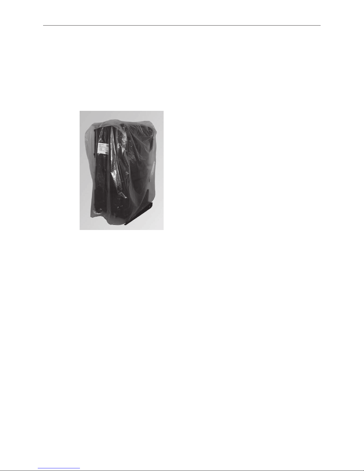
2.1.1 LogWIN Klassik
Boiler covered with a plastic sack.
The cladding, control panel and small parts can be found in the 2 cardboard boxes and in the filler chamber.
Fig. 2 LogWIN Klassik
2.1.2 Optional accessories
Fitted in control panel, if ordered:
– MESplus system control (installed and pre-wired)
Supplied with the boiler if ordered:
– Adapter for steplessly adjustable flue connection on left, right
– Exhaust gas sensor kit with protective tube
– Automatic ignition
– Thermal process safeguard
– Energy-saving intake regulator
– Return hold-up group
– Motorised mixing valve, mixer groups, heating distributor
– Cleaning kit
– Flue gas thermostat
7
2. For the Installer
2.2 System
2.2.1 Area of use
For heating buildings acc. to EN 12831.
The boilers are designed and approved as heat generators for hot water heating systems with a permissible flow
temperatures of up to 90°C. They may be installed only in sealed systems. The max. boiler temperature for the
LogWIN is limited in the factory to 80 °C.
The resulting flow temperature depends on the relevant operating status and the line losses to the system.
2.2.2 Standards
The following European standard should be followed: EN 12828, this specifies that the following should be fitted:
a) A closed expansion tank.
b) A reliably functioning safety valve (with max. 3 bar reaction pressure) installed at the highest point of the boiler
or at a non-closable line.
c) A thermometer, a pressure gauge.
d) An automatic device for dissipating heat which will prevent the maximum water temperature in the boiler of
110°C from being exceeded. The built-in thermal safety device (heat exchanger) should always be used with
the thermal discharge safeguard.
e) A low-water cut-off: A low-water cut-off is not required for systems providing up to 300 kW nominal thermal
output, if it can be ensured that a lack of water in the system will not result in excess heating.
If the boiler is above the radiators, then a low-water cut-off must be installed.
2.2.3 Accumulator tank
The installation of a buffer tank is required by the following standards / laws:
– EN 303-5
– 1st Federal Immission Control Ordinance (Germany)
– Art. 15a of the Small Combustion Devices Agreement (Austria)
– Air Protection Ordinance (Switzerland)
Having a correctly sized accumulator tank is essential for correct operation of a wood-fired heating system. The
fuel must always be selected and the heat load of the building calculated. Heating characteristics (e.g. bringing
the hot water tank up to temperature in summer) and the system configuration (ground and/or radiator heating
circuits) should also be taken into consideration.
Information!
Rooms that are not heated at times (guest rooms, living areas only used at weekends, etc.) must be
subtracted from the calculated heat load (QH) for the accumulator tank configuration!
Recommended accumulator tank content
Wood gasification Boiler model Recommended accumulator tank content:
LogWIN Klassik LWK 180 – 300 2000 l
Note!
Refer to planning documents for how to calculate the minimum buffer tank volume.

8
2. For the Installer
2.2.4 Heating circuits
Several heating circuits:
In-line regulating valves should be installed to permit better regulation of the system. In a building without insulation (new building, not yet plastered) the calculated and actually required heating requirements often differ to a
considerable extent.
Minimum heat consumption:
The smallest possible boiler power must be continuously dissipated from the boiler during operation. Suitable
measures to ensure minimum heat consumption should be maintained throughout the entire burning time, e.g.:
– Correctly dimensioned buffer tank - see2.2.3.
– Function of the MES plus–controller in the WVF+ function module on the master user module
incl. no thermostatic valves
– Non-blockable heating circuit, e.g. never fully close manual mixing valve, incl. no thermostatic valves
Note!
If operating with a manual mixing valve or the MES plus–function, elevated room temperatures may
sporadically occur.
Mixer valve:
A 3-way mixer valve is always necessary; in conjunction with outside temperature control, there must be a 3-way
motorised mixing valve and a buffer tank.
Underfloor heating:
Only possible with a buffer tank (with outside temperature control, motorised mixing valve).
Return flow temperature increase:
Required with LogWIN Klassik. It is essential that a return temperature of 61 °C be maintained during heating.
In order to achieve good temperature stratification in the heat accumulator or buffer tank, we recommend that
the boiler circuit be regulated. When using the return hold-up group SK RH 61 in connection with the stratified
charge function (MESplus function module WVF+), regulating the boiler circuit is no longer necessary.
Boiler start-up relief:
A boiler start-up relief must be installed and connected in all cases so that the circulation pump(s) are switched
off when the boiler temperature is below 60 °C. This prevents condensation forming in the boiler and extends its
service life.
A boiler start-up relief of this kind is contained in the MESplus control system.
2.2.5 Circulation pump
We recommend using pumps efficiency class A.
2.2.6 Heating water
a) The chemical composition of the heating water must meet the specifications of ÖNORM H 5195 Part 1 or VDI
2035 P1. According to ÖNORM H 5195 Part 1 (2010 edition), the condition of the heating water must be checked
every 2 years by a heating technician in order to avoid corrosion and sediment accumulation in the heating
system.
b) The pipe lines and heating appliances should be thoroughly rinsed before the boiler is connected.
c) To protect the boiler from contamination from the heating system, installation of a dirt trap is required in old
or existing systems (mesh size 0.5 mm) with maintenance cocks installed in the return line.
d) If oxygen diffusion or sludge build-up cannot be prevented, the system must be segregated by means of a heat
exchanger.
e) If antifreeze is used, a minimum volume of 20% antifreeze is required, otherwise corrosion prevention is not
guaranteed.
9
2. For the Installer
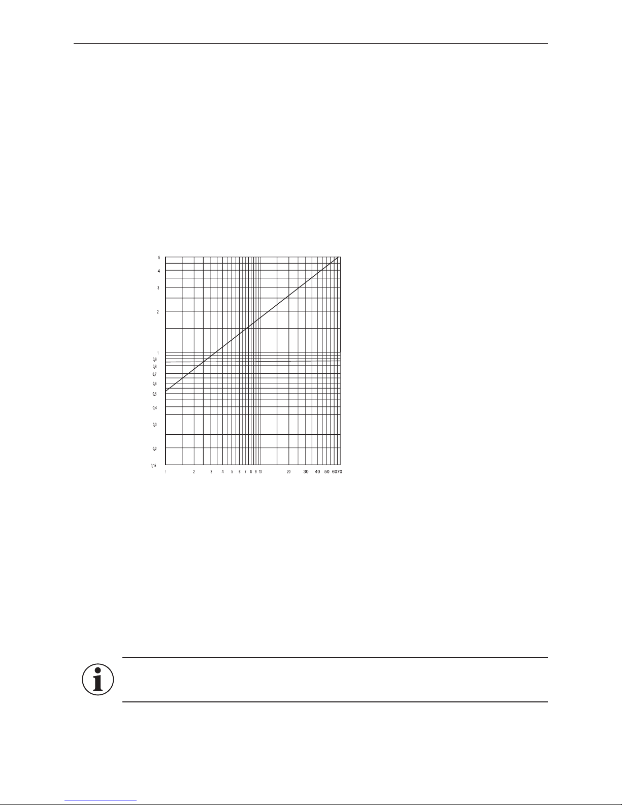
Diagram 1 water-side resistance
Pressure loss (mbar)
Flow rate (m
3
/h)
LWK 180 – 300
2.2.10 Combustion air
The combustion air is drawn directly by the device from the installation room, therefore the installation room has to
be adequately ventilated. The combustion air should be directed to the vicinity of the boiler and must be free from
pollutants (gases, vapours and dusts), otherwise malfunctions and increased wear (e.g. corrosion) may occur.
The area of the free minimum cross-section must be 5 cm2 per kW of the boiler‘s nominal total output1.
The opening to the outdoors for combustion air should be designed as follows:
– the flow of air must not be restricted in any way by the weather (e.g. snow, leaves),
– the free cross-section area remains the same when taking the cover grille, discs etc. into consideration.
Information!
Malfunctions or complaints occasioned by inadequate combustion air will not be covered by the
guarantee!
1 The boiler‘s nominal total output is the sum of the nominal outputs of all heat generators installed in the same boiler / installation room.
2.2.7 Domestic water (bringing the hot water tank up to temperature in
summer)
There may still be fuel in the boiler after the hot water tank has been brought up to temperature. As a result,
measures must be taken to dissipate the surplus energy – see 2.2.4 Heating circuits; Minimum heat consumption.
2.2.8 Combination with automatic boiler (e.g. pellet or oil-fired boiler)
If the LogWIN and an automatic boiler (e.g. pellet or oil-fired boiler) are connected to one flue without a MESplus
control, in the case of LogWIN a flue gas thermostat (accessory OK-050) must be installed to prevent parallel
operation on the same flue.
2.2.9 Water-side resistance (pressure loss)
10
2. For the Installer
2.4 Installation sequence
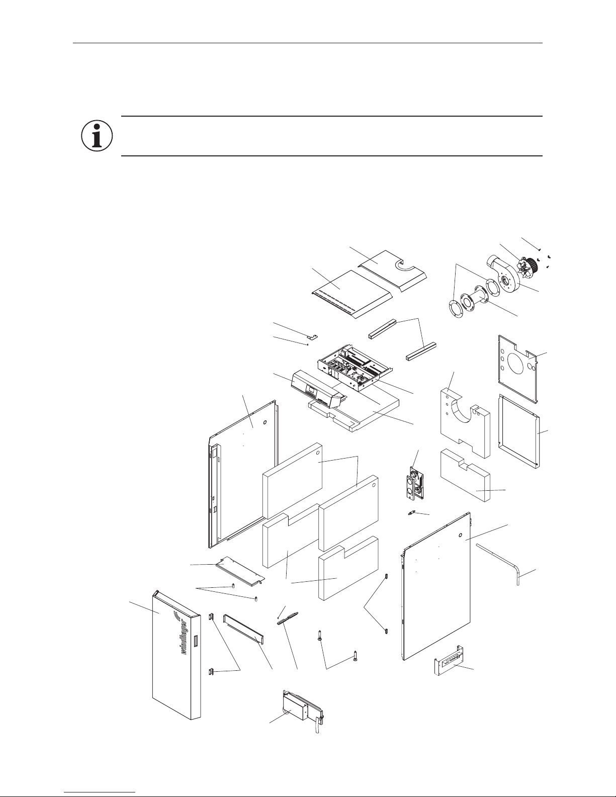
2.4.1 Parts designations for installation
Information!
All cladding parts must be fitted in full for air guidance and the dissipation of heat on the boiler.
20
2
3
4
5
6
7
8
9
10
11
12
13
14
15
27
17
18
19
1
21
22
22
23
24
25
2616
28
29
30
31
32
33
34
Fig. 4 Parts for installation
1 ...........Lower door hinge
2 ...........Carburisation gas duct
3 ...........Side panel left
4 ...........Side panel right
5 ...........Rear wall top
6 ...........Rear wall bottom
7 ...........Front boiler cover
8 ...........Rear boiler cover
9 ...........Hook-in plate ash pan
10 .........Bottom insulation, left/right
11 .........Top insulation, left/right
12 .........Top rear insulation
13 .........Bottom rear insulation
14 .........Top front insulation
15 .........Cladding door
16 .........Magnet retainer (2 pcs.)
17 .........Lever for cleaning heating surfaces
18 .........Carburisation gas duct attachment (2 pcs.)
19 .........Control panel
20 .........Upper door hinge
21 .........Control panel
22 .........Dog point screw (2 pcs.)
23 .........Cable channel (2 pcs.)
24 .........Lambda sensor
25 .........Air control
26 .........Set screws front (2 pcs.)
27 .........Magnetic catch (2 pcs.)
28 .........Blower seal
29 .........Flue connection adapter
- accessories
30 .........Blower housing
31 .........Flue gas blower
32 .........Wing nugs
33 .........Lighting door with
automatic ignition accessory
34 .........Hanger - accessory
11
2. For the Installer
2.4.2 Taking into the building and installing
The appliance must be taken into the building and installed without subjecting it to significant knocks and jolts,
in order to avoid damaging the combustion chamber and/or the parts slipping. The warranty will be invalidated if
the appliance is damaged due to having been taken into the building and installed incorrectly or if the appliance
malfunctions as a consequence of this.
The LogWIN may only be transported upright and without cladding and it is easiest to transport using a lift truck
or by rolling on pipes. When transporting via stairs and the such like, the boiler must be suitably secured. Also
refer to the technical data in section 4.5 for transport dimensions.
Note!
There is a crane lug on the top of the boiler for transport using hoisting winches. The weight can
be reduced by approx. 120 kg by removing parts which are easy to disassemble (e.g. doors, hook-in
plates, burnthrough plates, heating surface cleaning etc.).
The boiler can be installed directly on a non-flammable surface and does not require special foundations.
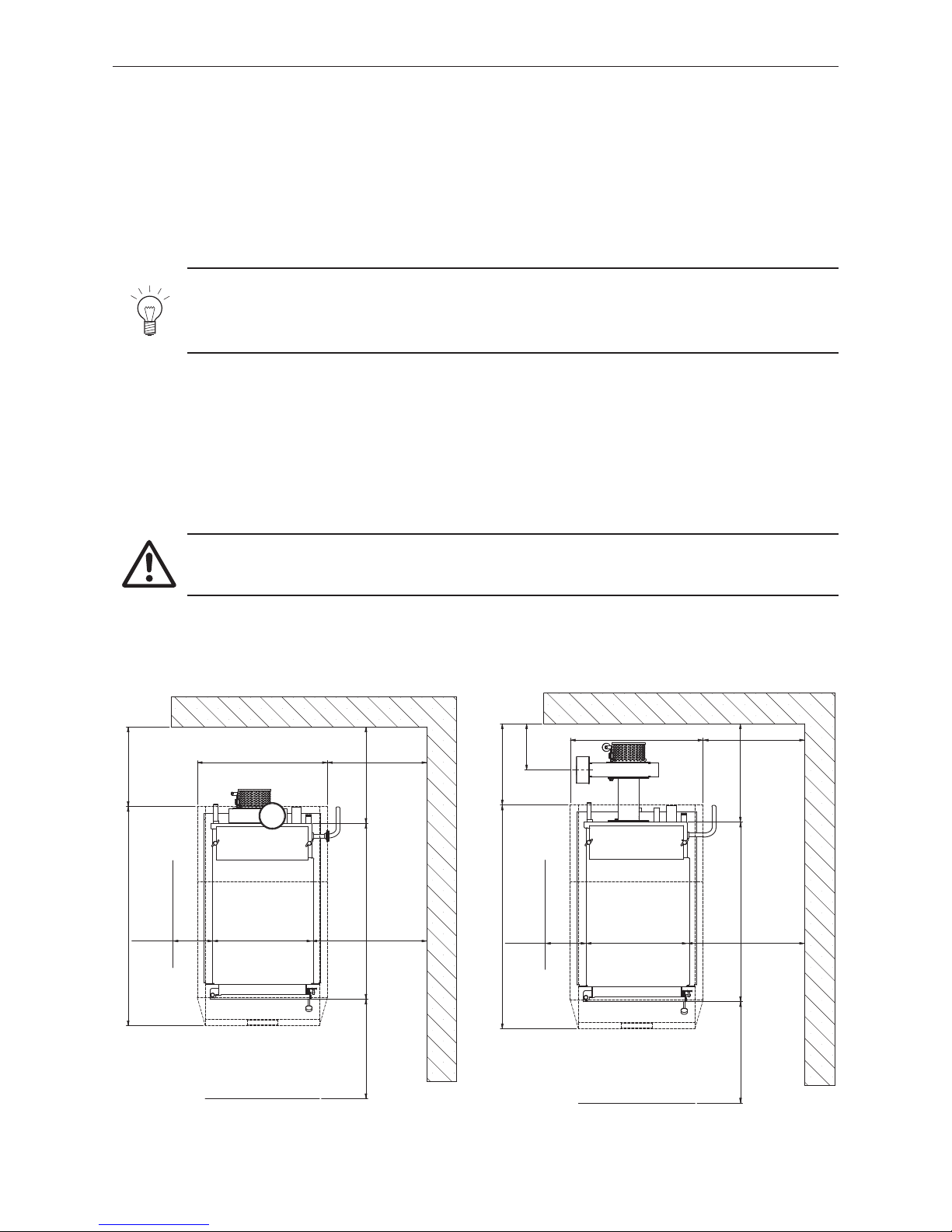
2.4.3 Minimum clearances
For maintenance and servicing it is essential to comply with the minimum clearances for the walls, hydraulic
components and connection pipes.
All dimensions in mm:
Recommended minimum room heights: 1850 mm
Attention!
Follow the installation guidelines for boiler rooms!
Fig. 5 LogWIN Klassik exhaust pipe upwards – top view
498
883
1102
654
min. 550
min. 400
min. 700
min. 628 min. 200
min. 485
Fig. 6 LogWIN Klassik with exhaust pipe adapter– top view
498
883
1102
654
min. 550
min. 400
min. 700
min. 628 min. 200
min. 228
min. 485
12
2. For the Installer
2.4.4 Prior to installation
Move the boiler to its definitive installation position and use the set screws to align it inclined slightly upwards
towards the rear. If it is not possible to level the unit using only the rear set screws, two additional set screws
can be installed at the front – Fig. 8.
The cladding door and the boiler doors are designed for door catches on either the left or right. Standard delivery
always includes door catches on the left. The catches on the cladding door and boiler doors must be on the same
side.
Prior to installing the set screws, the lower door hinge and the dog point screw for attaching the cladding door
must be mounted either on the left or right, depending on which side the door catches are to be located. – Fig. 7.
Fig. 7 Install door hinge for cladding door
left or right
2 x
1 x
Fig. 8 Install two set screws in the front
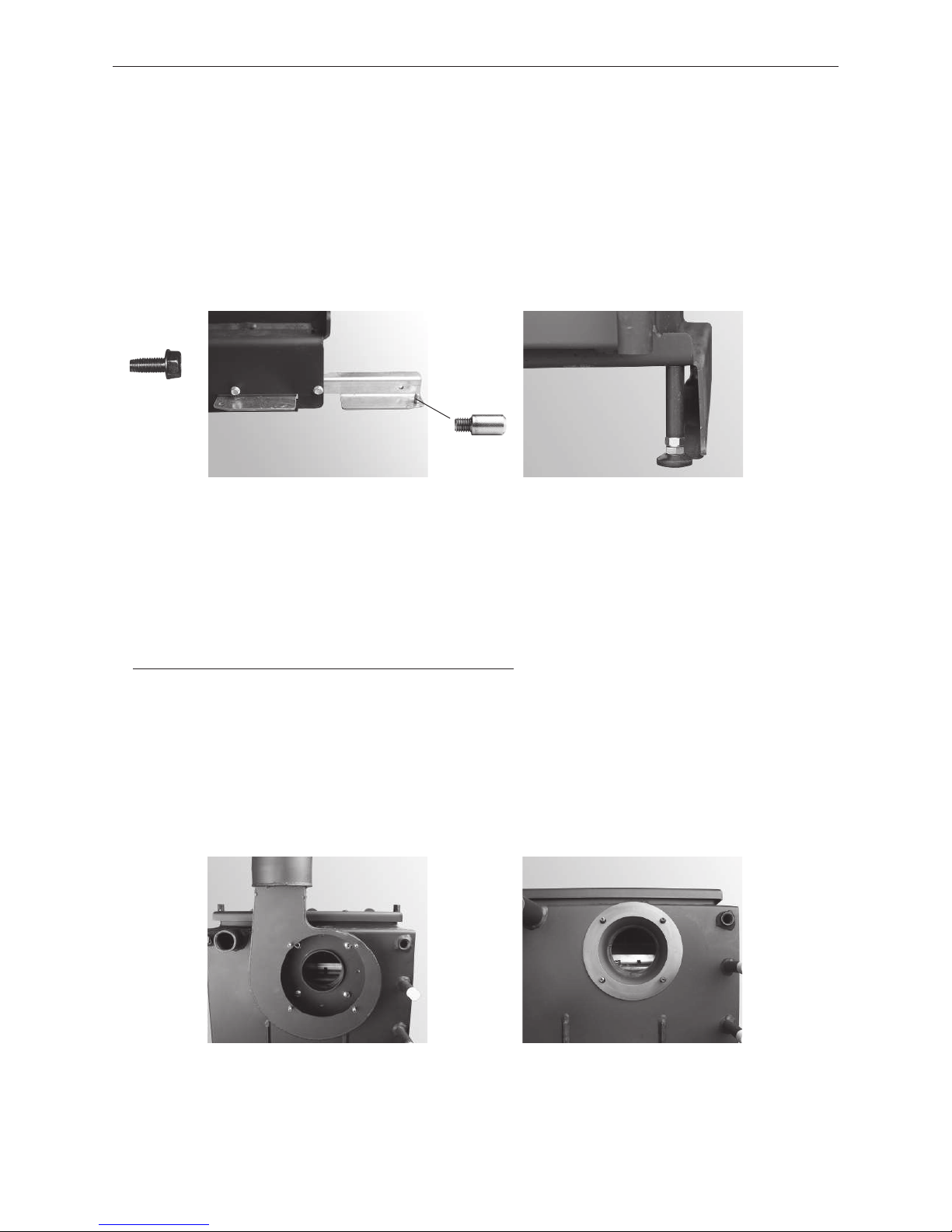
2.4.5 Installing the flue connection adapter
– Only for LogWIN with flue connection adapter (accessories)
Standard installation of the blower housing is directly on the boiler – Fig. 9 è flue connection at top.
With the adapter (accessories), the blower housing is located outside the cladding – Fig. 12. The flue connec-
tion is steplessly adjustable from left to right – Fig. 11.
– Unscrew 4 interior nuts in the blower housing (Fig. 9) and remove the housing. Do not remove the seal – Fig.10.
Fig. 9 Glower housing directly on boiler –
standard
Fig. 10 Seal on boiler
13
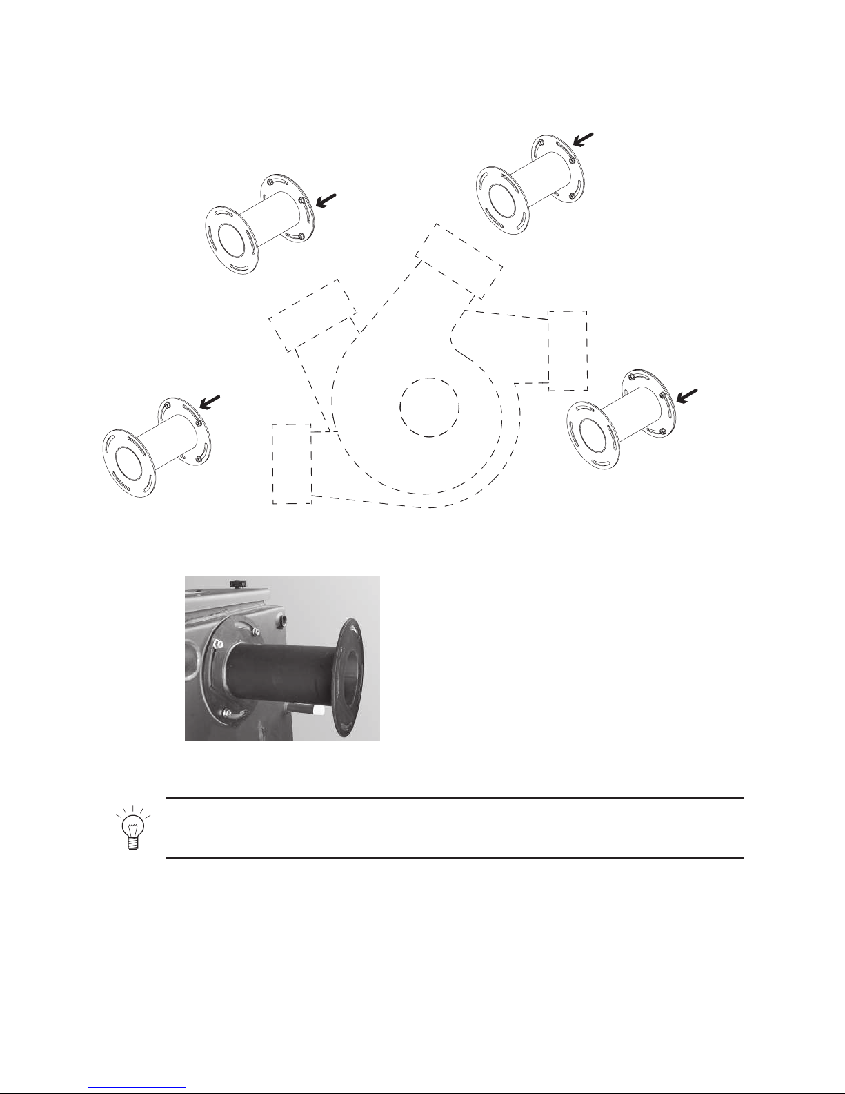
2. For the Installer
Note!
Do not screw the blower housing onto the adapter until the rear panel has been installed – otherwise
the rear panel cannot be installed.
– Secure adapter, with slot position depending on desired angle of flue connection, on boiler according to Fig. 11
with seal and 4 M8 nuts – Fig. 11, 12.
0°- 45°
45°- 90°
90°- 135°
135°- 180°
0°- 45°
45°- 90°
90°- 135°
135°- 180°
Fig. 11 Installation of adapter depending on angle of flue connection
Fig. 12 Adapter on the boilder (accessories)
Boiler side
Boiler side
Boiler side
Boiler side
14
2. For the Installer
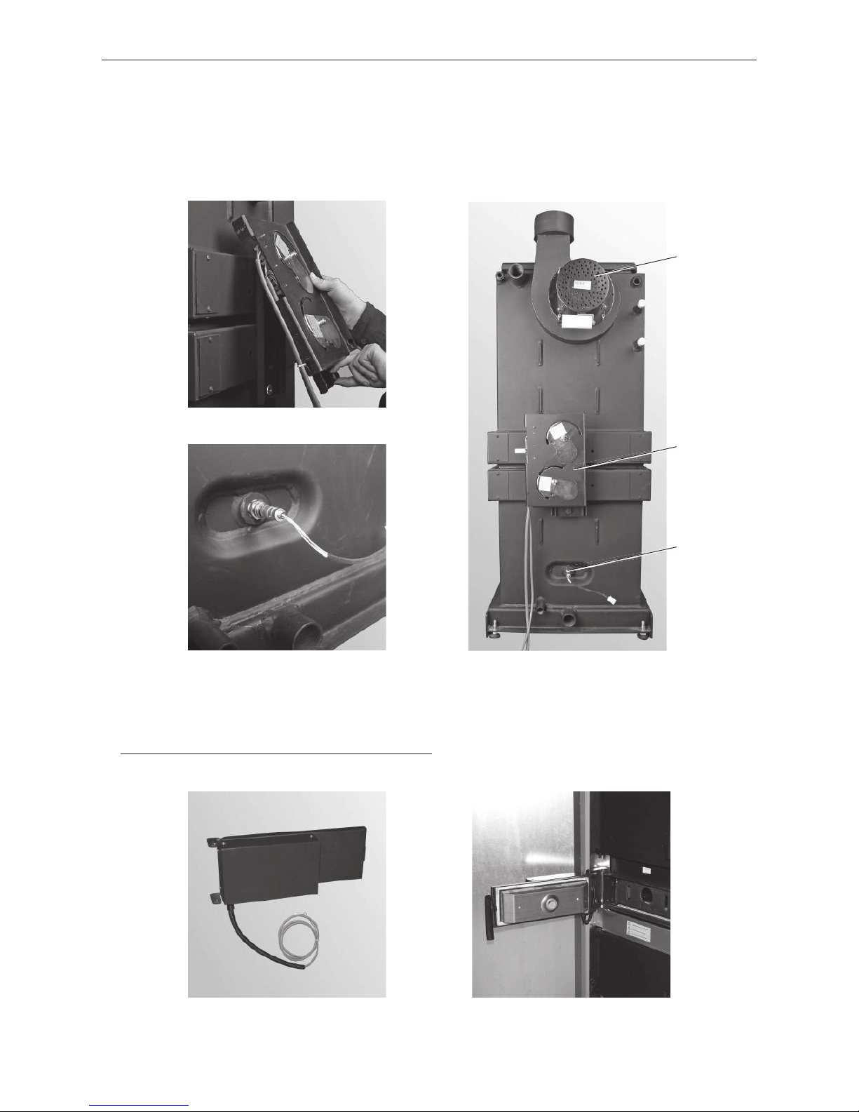
2.4.6 Installing the flue gas blower, air control and lambda sensor
– Screw the flue gas blower to the blower housing with 4 wing nuts – Fig. 15.
– Hook in the air control at the top and secure with screw at the bottom – Fig. 13, 15.
– Screw the lambda sensor in finger tight and tighten approx. 1/4 turn with an open-ended wrench (SW 22) –
Fig.14, 15.
Fig. 13 Hooking in air control at top and
screwing on at bottom
Fig. 14 Lambda sensor installed
2.4.7 Installing the lighting door with automatic ignition
– Only for LogWIN with automatic ignition (accessories) see separate installation instructions (included).
Fig. 15 Flue gas blower, air control and
lambda sensor installed
Fig. 16 Automatic ignition Fig. 17 Lighting door with automatic ignition
Flue gas blower
Air control
Lambda sensor
15
2. For the Installer
2.4.8 Installing the carburisation gas duct
– Screw in 2 fasteners for the carburisation gas duct over the heating door on the boiler, see Fig. 18, 19.
– Attach the carburisation gas duct and screw tight with 2 M8 nuts – Fig. 20.
Fig. 18 Installing 2 fasteners for carburi-
sation gas duct
Fig. 19 2 fasteners installed
Fig. 20 Installing the carburisation gas
duct
2.4.9 Installing the insulation
– Attach insulation on top and sides, see Fig. 21, 22.
Fig. 21 Installing insulation
Fig. 22 Installing insulation
2 x
Fasteners
16
2. For the Installer
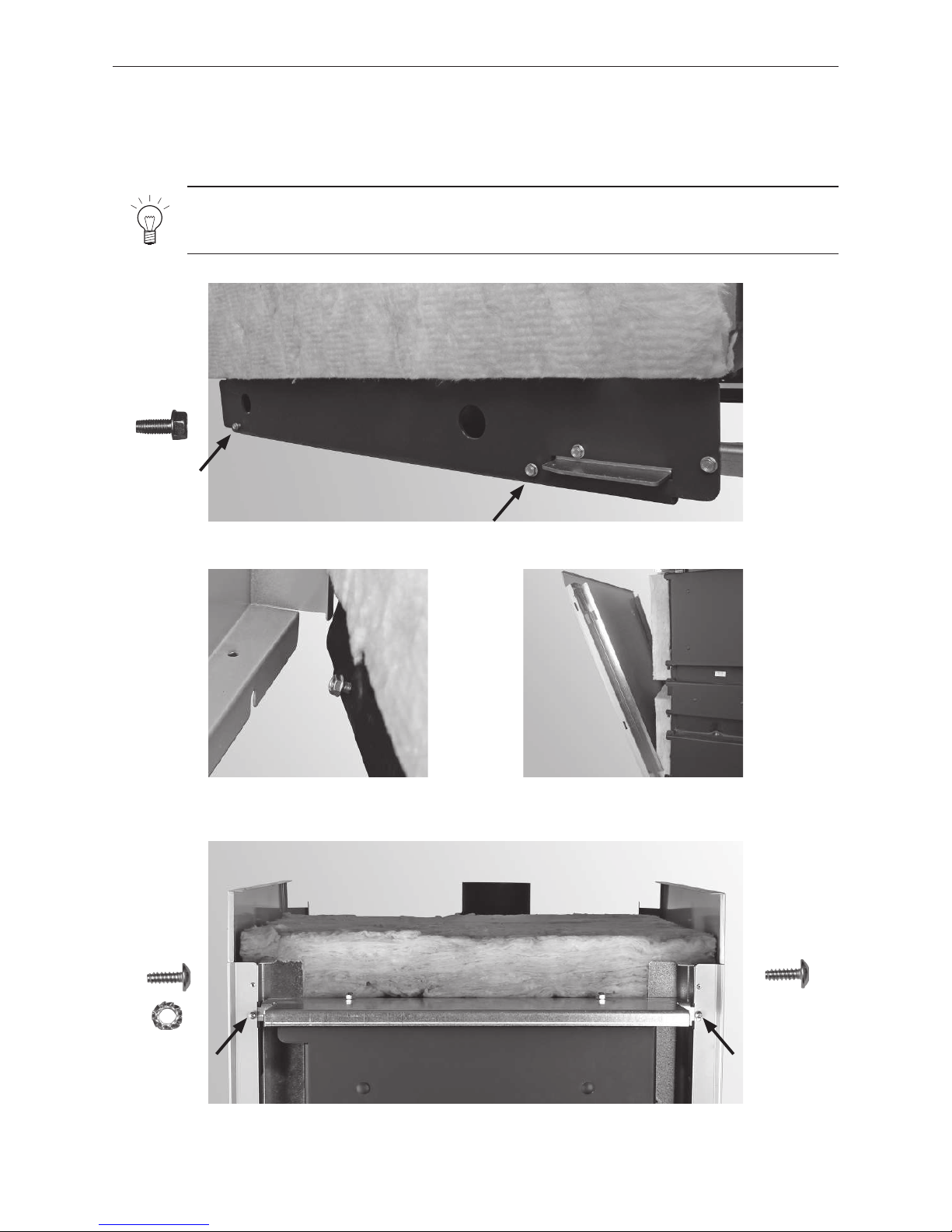
2.4.10 Installing the side panels
– Screw in 2 screws on the bottom of each side of the base halfway – Fig. 23. Release the side panels and hook
them into the installed screws at the bottom (Fig. 24, 25) and loosely screw the top on with one self-tapping
screw and one saw tooth ring for earthing – Fig. 26.
Fig. 23 Screw in 2 screws on each side of the base
Fig. 24 Hooking the side panels in with screws at the
bottom
2 each of
Note!
Only screw the cladding screws on loosely at first; do not adjust the cladding (gap size) and tighten
all screws until all cladding parts have been installed.
Fig. 25 Hooking in side panels
Fig. 26 Screws the side panels on loosely at the top front.
1 x1 x
17
2. For the Installer
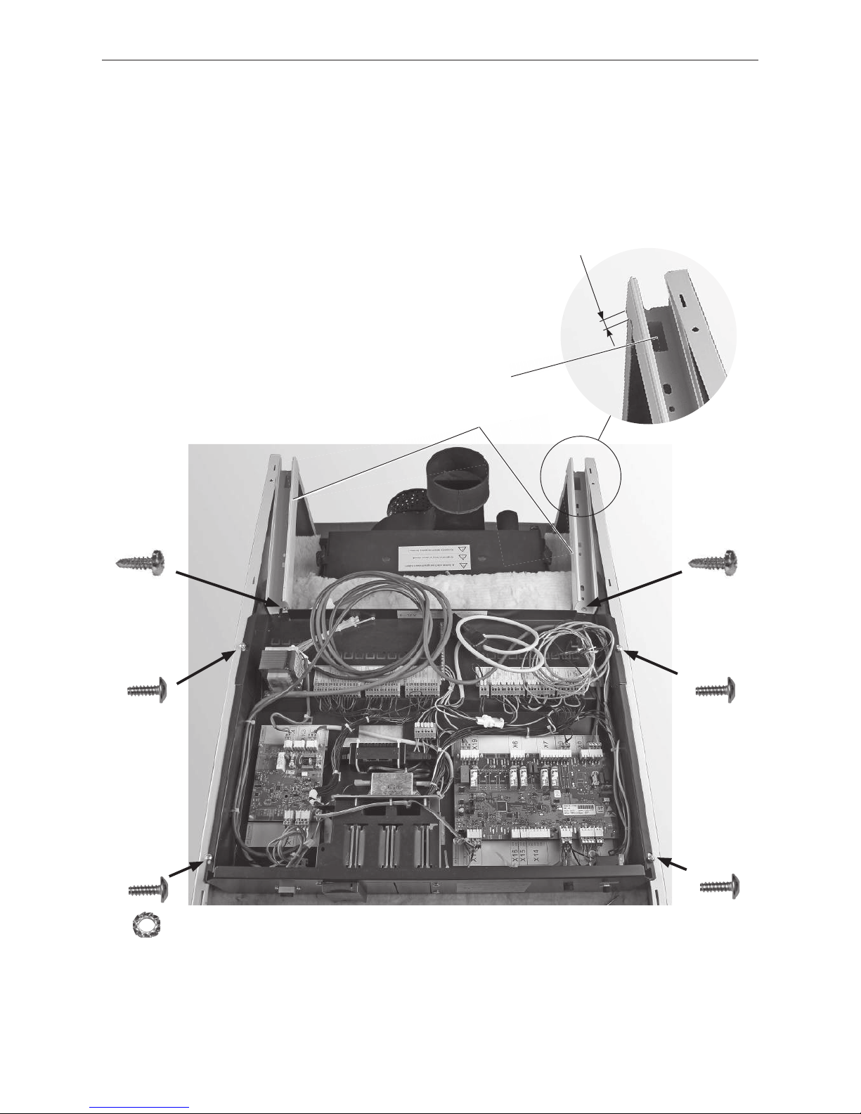
2.4.11 Installing the control panel
– Place the control panel on the side panels and attach it to each with 2 self-tapping screws and 1 saw tooth ring
for earthing – Fig. 27.
– Attach the cable channels at left and right (feed-through at rear) with a drilling screw on each side to the front
of the control panel; leave some overhang over the cladding at the rear (approx. 5 mm) – Fig. 27. Cable routing,
see Fig. 33 and Item 3.
Fig. 27 Screw the control panel on loosely; screw the cable channels tight.
1 x
1 x
1 x
Cable channels
1 x
1 x
1 x
Feed-through
approx. 5 mm
18
2. For the Installer
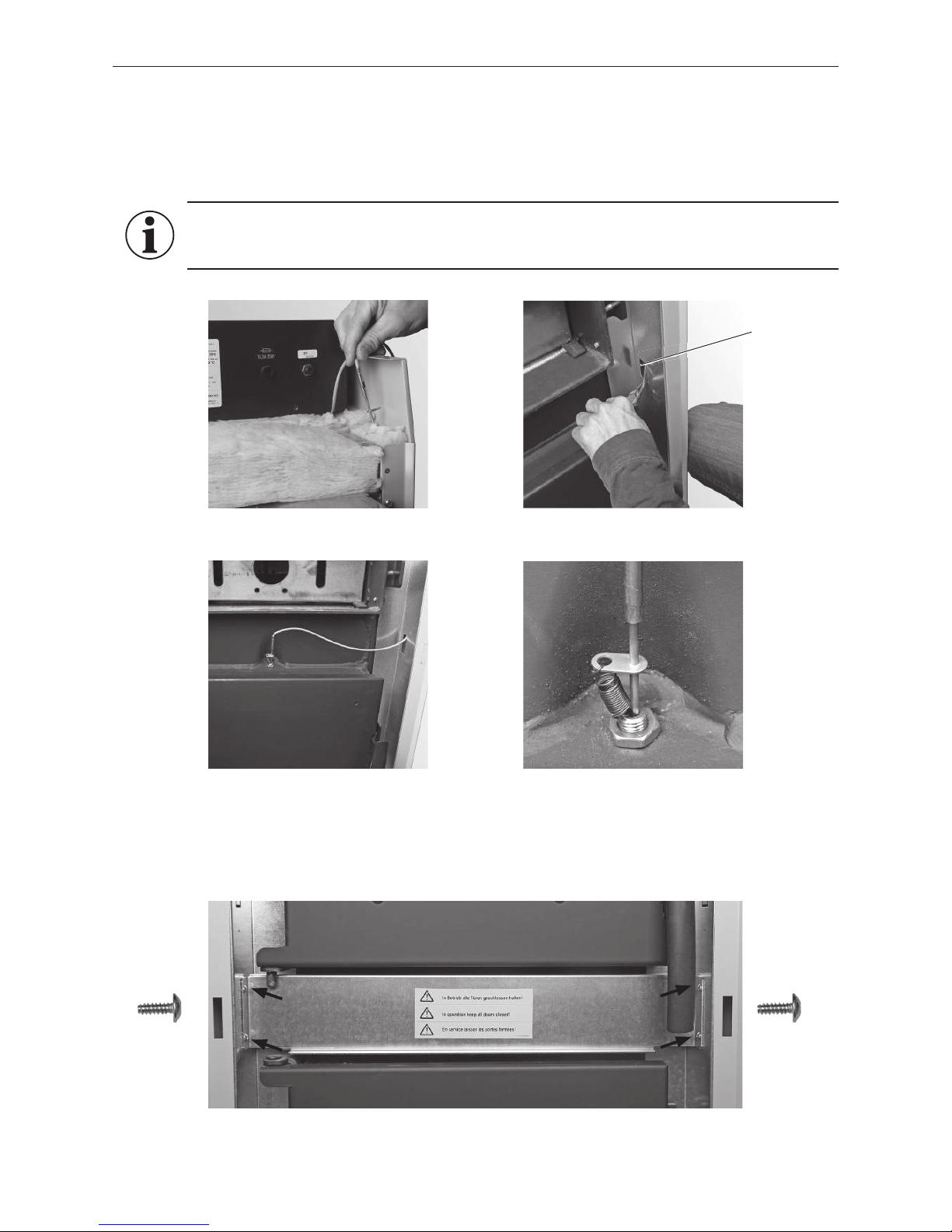
2.4.12 Installing the thermocontrol sensor
– Route the thermocontrol sensor (green cable) at the front of the right side panel down and feed through –
Fig.28, 29. But first bend the cut-out (feed-through) at the bottom of the side panel out of the way.
– Insert the sensor over the ash door in the front and into the protective tube; hook the spring in place – Fig.30,31.
Fig. 28 Inserting the thermocontrol sensor at the top
Fig. 29 Threading through thermocontrol
sensor
Fig. 30 Securing the thermocontrol sensor with
spring, pulling cable back
Fig. 31 Thermocontrol sensor with spring
2.4.13 Installing the thermocontrol sensor cover
– Attach the thermocontrol sensor with 4 self-tapping screws – Fig. 32.
Fig. 32 Attaching the cover over the thermocontrol sensor with 4 screws
2 each of 2 each of
Cut-out feedthrough
Information!
Pull the protruding cable from the thermocontrol sensor back into the side panel or control panel.
The cable may not hang out in order to keep it from becoming caught in the ash door.
19
2. For the Installer
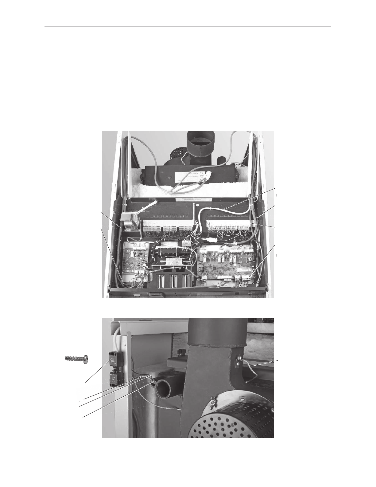
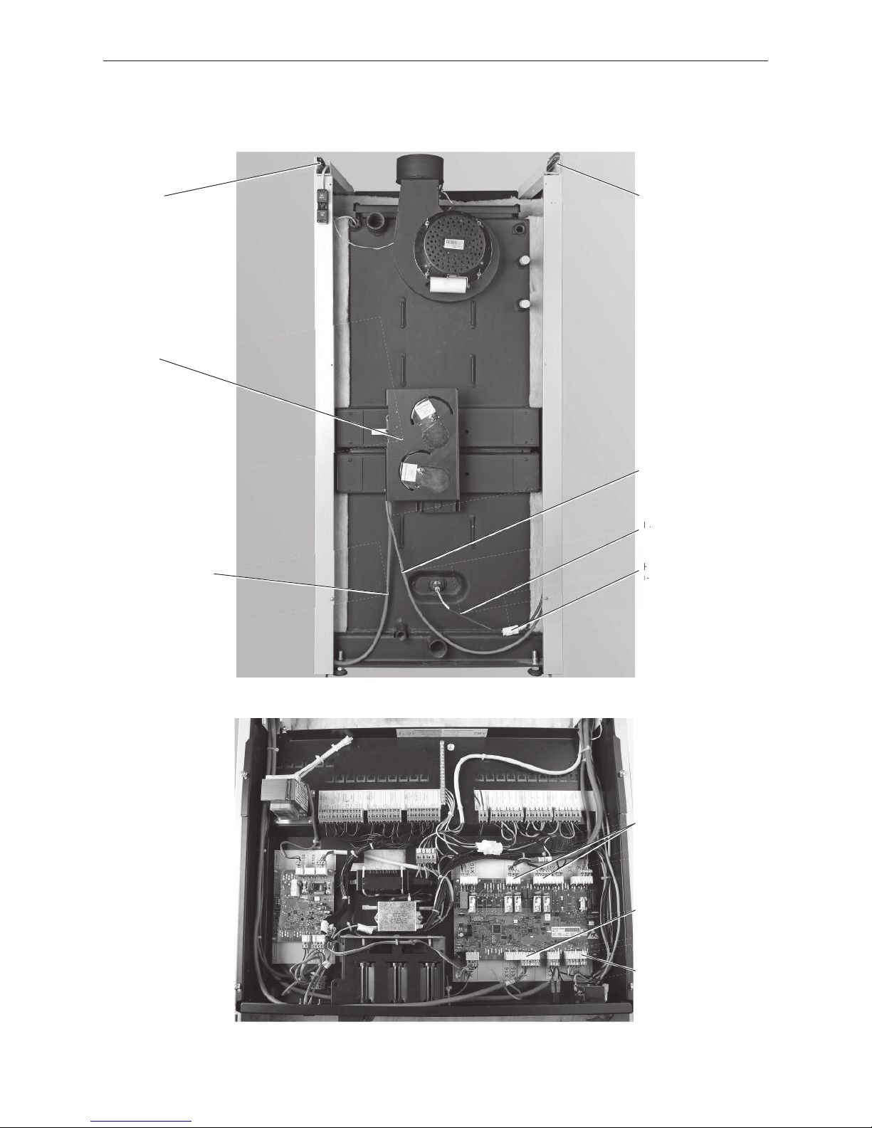
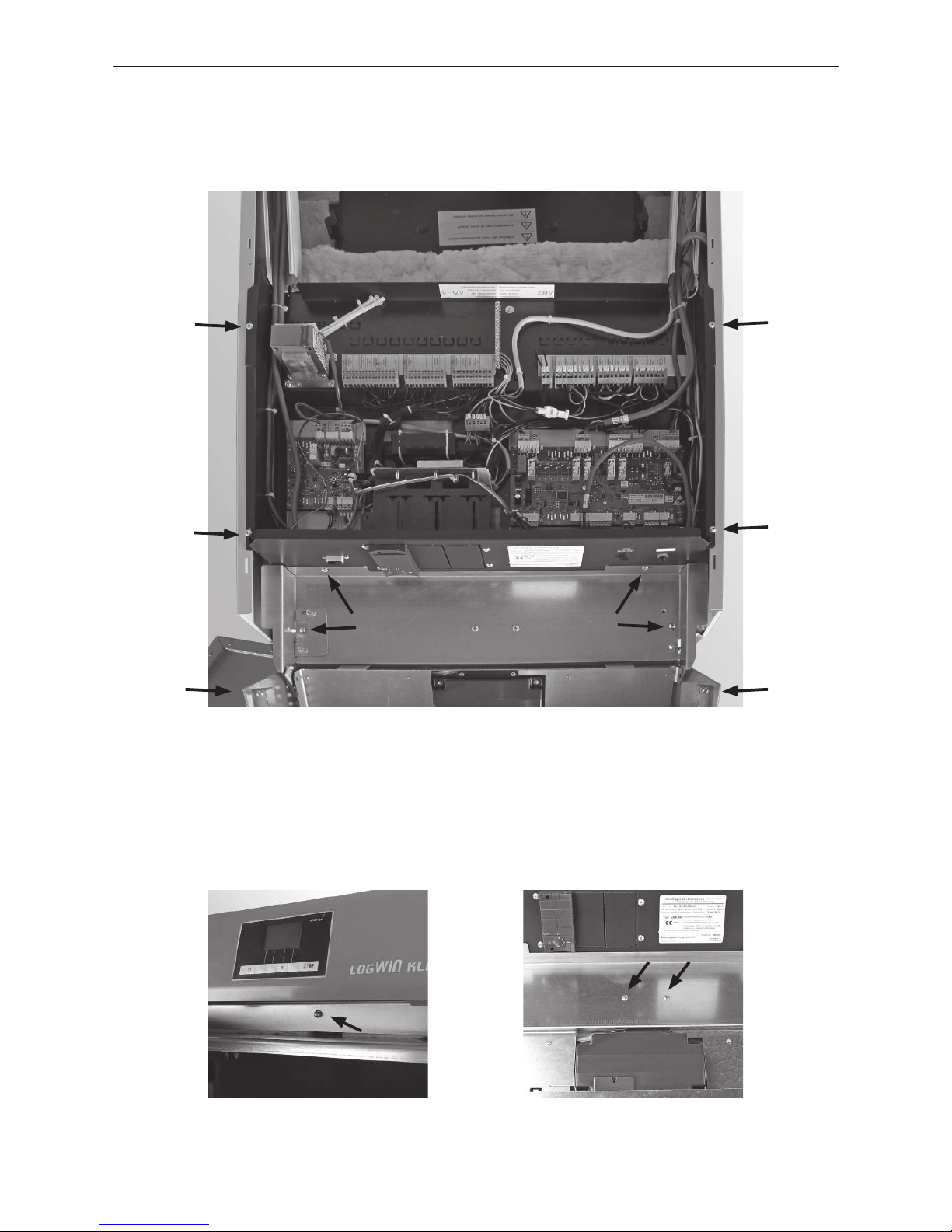
2.4.14 Installing the mains connection and sensor
– Route the mains cable and sensor lines in the right cable channel toward the back – Fig. 33. Plug the flue gas
sensor (accessories) in the control panel to Plug X11 and also route it in the right cable channel toward the
back. Route all sensor lines through the feed-through in the cable channel downward.
– Screw the power socket to the rear of the side panel with two 2.9 x 16 self-tapping screws – Fig. 34.
Insert boiler sensor and safety temperature limiter sensor (STB) as far as possible into the immersion sleeve and
secure them with the sensor guard to prevent them from slipping out – Fig. 34.
– Install the flue gas sensor with protective tube (accessories) into the flue outlet as described in the installation
instructions – Fig. 34.
– Route both cables for the flue gas blower in the cable channel stoward the back – Fig. 34.
Fig. 33 Control panel, cable routing
Cable with
power plug
Boiler sensor and
STB sensor
Cable from flue gas blower
Flue gas sensor
(accessories)
Plug X11
Fig. 34 LogWIN Klassik – rear side
Power socket
Boiler sensor
STB sensor
Sensor guard
Exhaust gas sensor
with protective tube
(accessories)
Cable from flue gas blower
Cable from lambda sensor
r
2 x
20
2. For the Installer
– Route both cables from the air control in the side panels upward via the cable channel feed-through into the
control panel as shown in Fig. 35 and connect as shown in Fig. 36.
– Route the lambda sensor cable from the control panel via the cable channel feed-through in the side panel
downward and connect to the lambda sensor – Fig. 36.
Fig. 35 LogWIN Klassik with rear panels removed – rear view
Air control cable with
Plug X6/X7
Air control cable with
Plug X14
Lambda sensor cable
Cable duct
Extra-low voltage
(0 – 12 VDC)
Air control
Cable duct
Low voltage
(230 V AC)
Fig. 36 LogWIN Klassik control panel – top view
Plug to
lambda sensor
Air control cable with
Plug X14
Air control cable with
Plug X6/X7
Flue gas sensor
(accessories) Plug X11
21
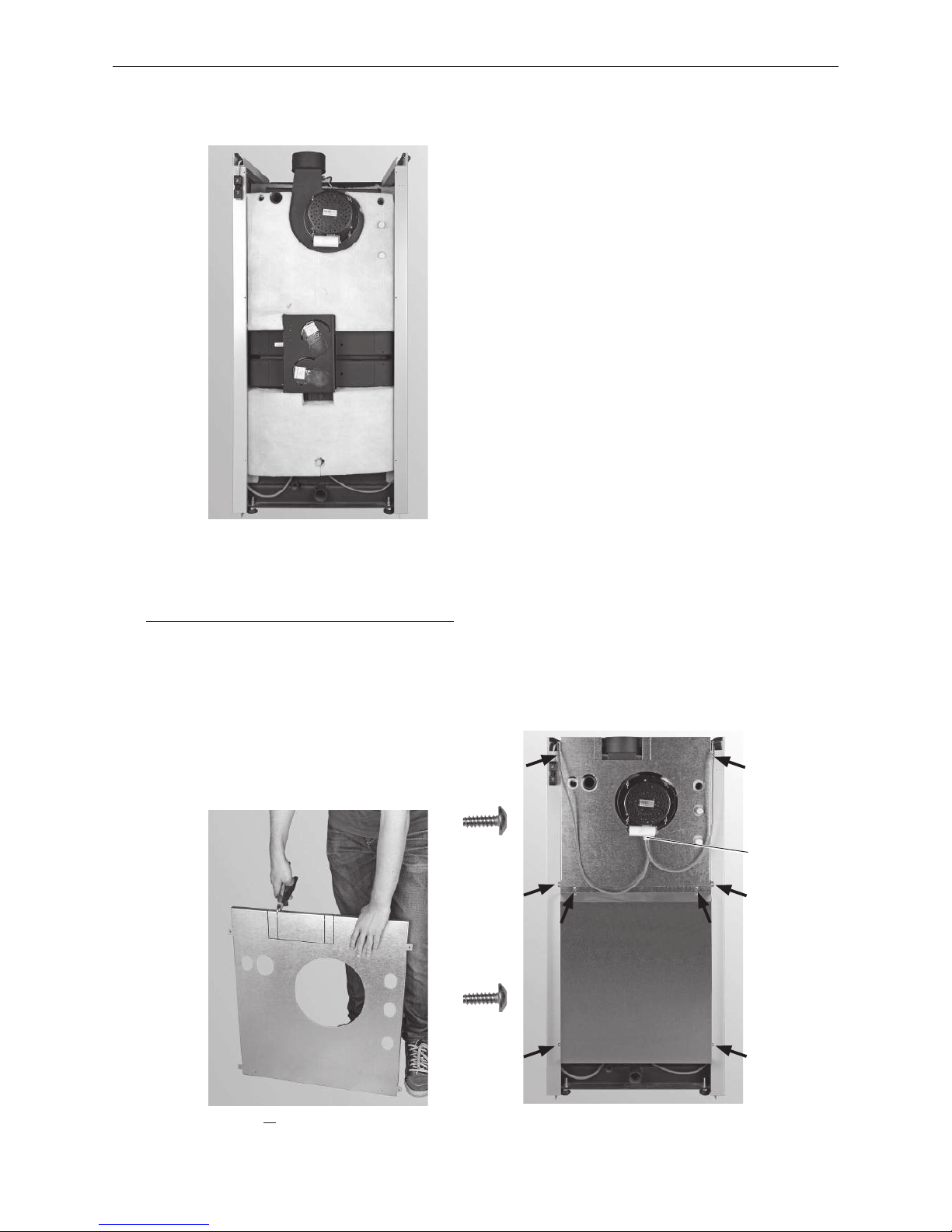
2. For the Installer
2.4.15 Installing insulation for the rear panel
– Install insulation on top and bottom as shown in Fig. 37.
Fig. 37 Installing insulation on the rear panel
Fig. 38 If no adapter for the flue connection is be-
ing used, break off the cut-out
2.4.16 Installing the rear panels
– If no adapter for the flue gas blower (accessories) is being used, break off the cut-out at the top of the back
panel – Fig. 37. large cut-out = exhaust pipe insulated
small cut-out = exhaust pipe not insulated
do not break off = adapter for flue connection installed
– Fasten the rear panel at top and bottom with 4 screws each – Fig. 39.
– Connect the blower plug to the flue gas blower – Fig. 39.
Fig. 39 Fitting the rear panels
4 each of
4 each of
Blower plugs

22
2. For the Installer
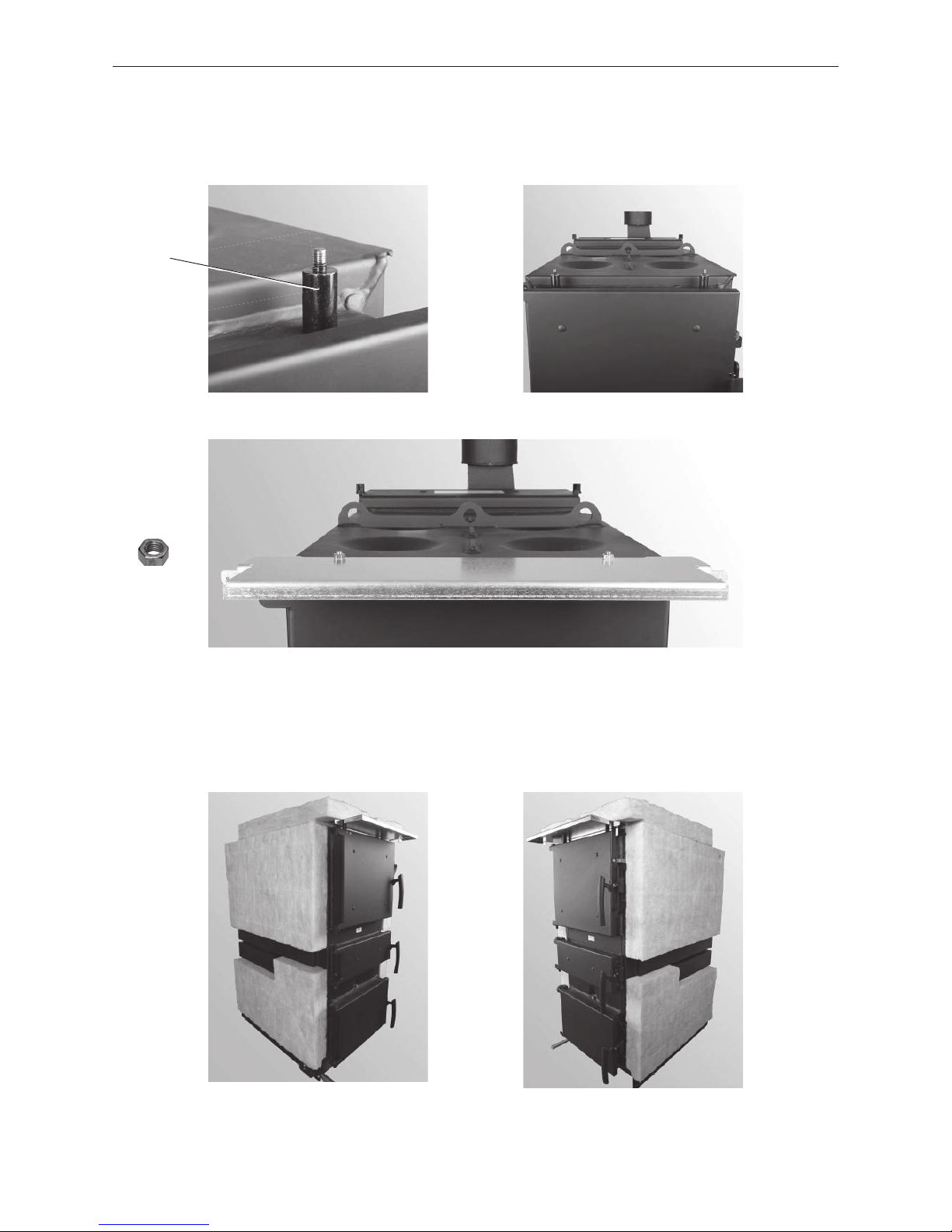
2.4.18 Installing the lever for cleaning heating surfaces
– Depending on accessibility, either install lever for cleaning heating surfaces on the left or right side. Punch
through the cut-out, insert lever through opening in side panel (Fig. 41) and slide inwards through the cleaning
heating surfaces axle (limit stop must face upwards – Fig. 42) and secure with screws (inserted only) – Fig. 42.
2.4.17 Installing the blower housing on the adapter
– Only for LogWIN with flue connection adapter (accessories)
– First screw the 4 included M8 x 16 hexagon screws into the blower housing from the inside, the attach the
blower housing with seal, 4 nuts and washers to the adapter – Fig. 40.
Fig. 40 Installing the blower housing on the adapter
Fig. 41 Punching through the cut-out, inserting lever
for cleaning heating surfaces through opening
Fig. 42 Sliding lever through axle and secur-
ing with screw (inserted only)
Limit stop
23
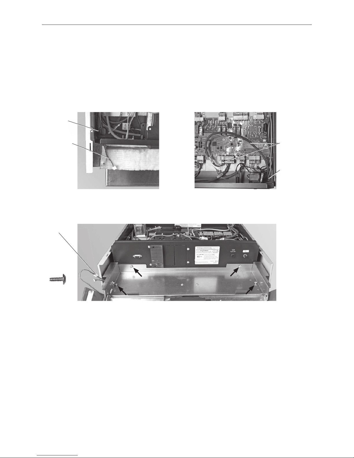
2. For the Installer
2.4.19 Installing the control panel
– Before the control panel is installed, the InfoWIN cable must be routed from the control panelat the front left
– Fig. 43.
– Route the cable from the door switch (on the control panel) at the front right into the control panel and connect
Plug X15 – Fig. 44.
– Loosely screw the control panel to the side panels (2 x) and control panel (2 x) with self-tapping screws –
Fig.45.
– Connect the InfoWIN cable and route into the side panel – Fig. 45.
Fig. 43 Threading the InfoWIN cable through
Fig. 44 Inserting the cable from the door
switch and connecting to Plug X15.
Door switch
cable and Plug
X15
Fig. 45 Attach the control panel with 4 self-tapping screws, route InfoWIN cable.
4 x
InfoWIN cable
InfoWIN
plug
Control panel
feed-through
Control panel
feed-through
24
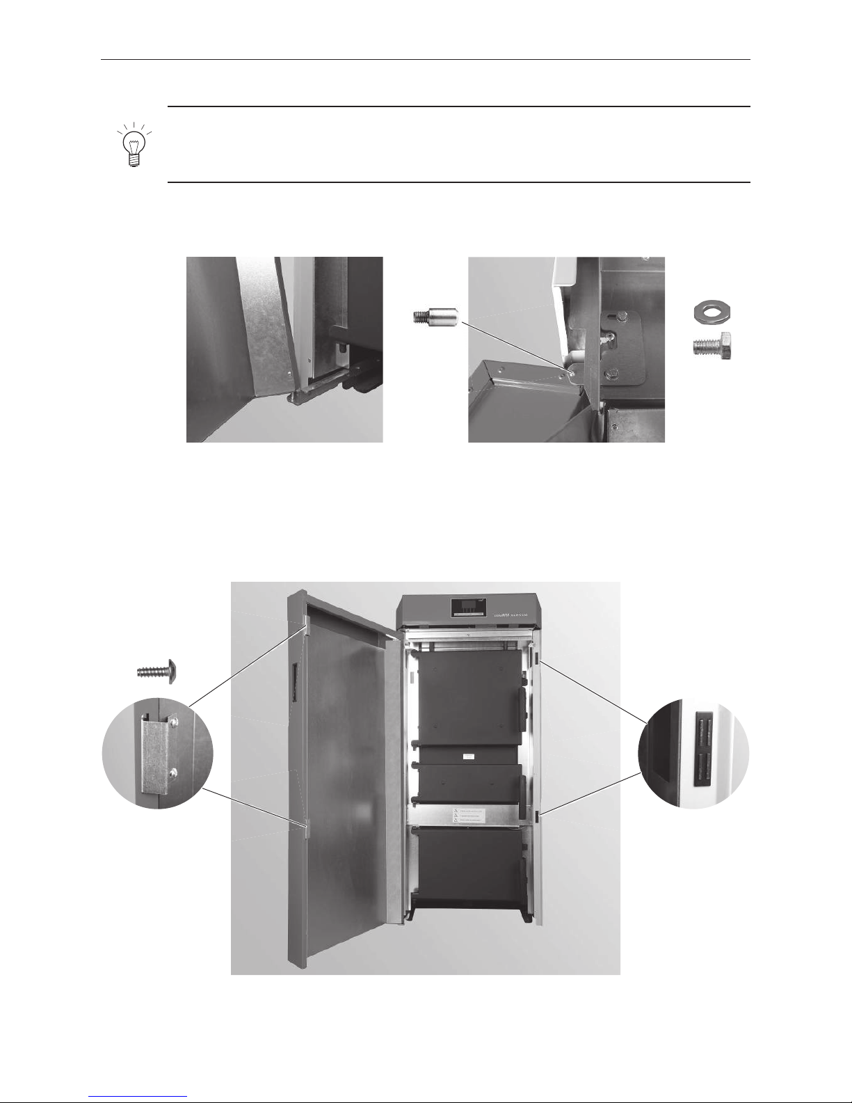
2. For the Installer
– Press 2 magnetic catches top/bottom into the side panel to align with the door catch side – Fig. 48.
– Install 2 magnet retainers top/bottom in the cladding door with 2 self-tapping screws each – Fig. 48.
Note!
The cladding door and the boiler doors are designed for door catches on either the left or right.
Standard delivery always includes door catches on the left. The catches on the cladding door and
boiler doors must be on the same side.
Fig. 46 Lower cladding door on door hinge
Fig. 47 Upper cladding door with door hinge
2.4.20 Installing the cladding door
Fig. 48 Screw the hinge into the cladding door with 2 self-tapping screws on each
side, press 2 magnetic catches into place
2 each of
Hook the cladding door in at the upper and lower door hinges (Fig. 46) and fasten the upper door hinge with 2
washers and M6x10 hexagon screws – Fig. 47.
2 each of
1 x
M6x10
25
2. For the Installer
2.4.22 Checking the cladding door switch
– When closing the cladding door, the cladding door switch must still have sufficient shifting travel after switch-
ing (audible clicking) before the cladding door is totally closed – Fig. 50. If necessary, use a screwdriver at the
top inside the control panel to reset – Fig. 51.
2.4.21 Adjusting the cladding
– Adjust side panels, cladding door and control panel visually by the width of the cladding door or equal gap size
and tighten all screws – Fig. 49.
Fig. 49 Adjusting cladding, tightening all screws
Fig. 50 Door switch must click Fig. 51 Reset door switch with screws
26
2. For the Installer
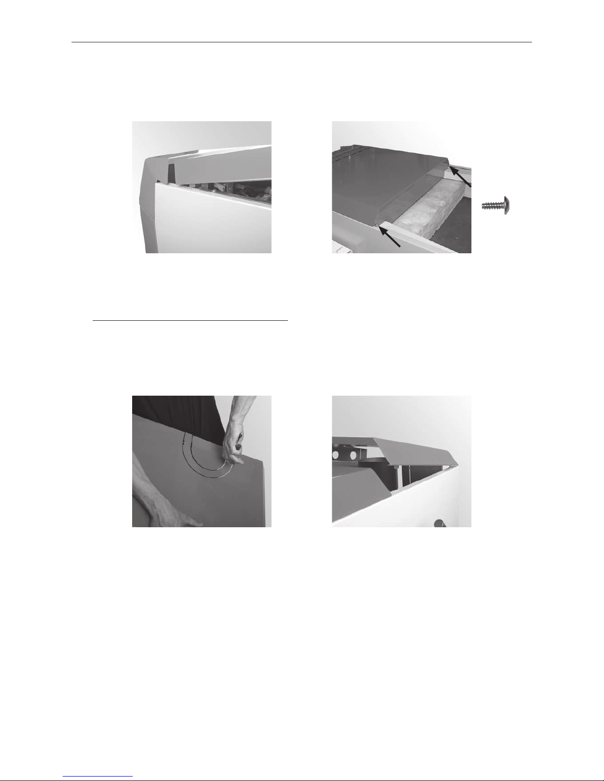
2.4.23 Mounting the front boiler cover
– Hook the front boiler cover into the side panels (Fig. 52) and attach at rear with 2 self-tapping screws – Fig. 53.
Fig. 52 Hinging in boiler cover Fig. 53 Securing boiler cover in 2 places
2 x
2.4.24 Mounting the rear boiler cover
– If no adapter for the flue gas blower (accessories) is being used, break off the cut-out at the rear of the boiler
cover – Fig. 54. large cut-out = exhaust pipe insulated
small cut-out = exhaust pipe not insulated
do not break off = adapter for flue connection installed
– Hook the rear boiler cover into the slot provided on the side panel cladding – Fig. 55.
Fig. 54 Punching out the rear boiler cover Fig. 55 Hooking in the rear boiler cover
 Loading...