

Page 1
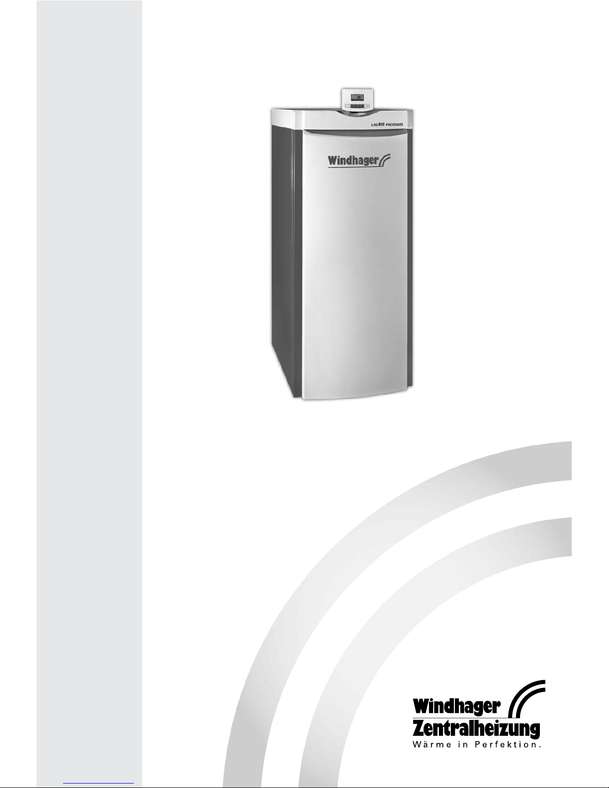
Assembly instructions
08/2008 xxxxxx/00
LogWIN
Wood gasification boiler
Page 2

2
Table of contents: Page
Important initial information for the Technician . . . . . . . . . . . . . . . . . . . . . . . . . . . . .3
1.1 Safety . . . . . . . . . . . . . . . . . . . . . . . . . . . . . . . . . . . . . . . . . . . . . . . . . . . . . . . . . . . . . . . . . . . . .3
1.2 Please note! . . . . . . . . . . . . . . . . . . . . . . . . . . . . . . . . . . . . . . . . . . . . . . . . . . . . . . . . . . . . . . .3
1.3 Flue . . . . . . . . . . . . . . . . . . . . . . . . . . . . . . . . . . . . . . . . . . . . . . . . . . . . . . . . . . . . . . . . . . . . . .3
For the Installer . . . . . . . . . . . . . . . . . . . . . . . . . . . . . . . . . . . . . . . . . . . . . . . . . . . . . . .4
2.1 Delivery, packaging . . . . . . . . . . . . . . . . . . . . . . . . . . . . . . . . . . . . . . . . . . . . . . . . . . . . . . . . .4
2.2 Taking into the building and installing . . . . . . . . . . . . . . . . . . . . . . . . . . . . . . . . . . . . . . . . . .5
2.3 Dimensional sketches . . . . . . . . . . . . . . . . . . . . . . . . . . . . . . . . . . . . . . . . . . . . . . . . . . . . . . . .7
2.4 System . . . . . . . . . . . . . . . . . . . . . . . . . . . . . . . . . . . . . . . . . . . . . . . . . . . . . . . . . . . . . . . . . . . .8
2.5 Installing the cladding . . . . . . . . . . . . . . . . . . . . . . . . . . . . . . . . . . . . . . . . . . . . . . . . . . . . . .12
2.6 Installing the exhaust pipe . . . . . . . . . . . . . . . . . . . . . . . . . . . . . . . . . . . . . . . . . . . . . . . . . .20
2.7 Installing the thermal process safeguard . . . . . . . . . . . . . . . . . . . . . . . . . . . . . . . . . . . . . . .20
2.8 Storing the instruction booklets . . . . . . . . . . . . . . . . . . . . . . . . . . . . . . . . . . . . . . . . . . . . . .21
2.9 Initial start-up and operating instructions . . . . . . . . . . . . . . . . . . . . . . . . . . . . . . . . . . . . . .21
For the Electrician . . . . . . . . . . . . . . . . . . . . . . . . . . . . . . . . . . . . . . . . . . . . . . . . . . . .22
3.1 Electrical connections . . . . . . . . . . . . . . . . . . . . . . . . . . . . . . . . . . . . . . . . . . . . . . . . . . . . . .22
For the Service Technician . . . . . . . . . . . . . . . . . . . . . . . . . . . . . . . . . . . . . . . . . . . . . .25
4.1 Service and repair work . . . . . . . . . . . . . . . . . . . . . . . . . . . . . . . . . . . . . . . . . . . . . . . . . . . . .25
4.2 Checking and servicing the thermal process safeguard . . . . . . . . . . . . . . . . . . . . . . . . . . .25
4.3 Technical data for calculating the flue gas system acc. to EN 13384-1 . . . . . . . . . . . . . . .26
4.4 Technical data – General . . . . . . . . . . . . . . . . . . . . . . . . . . . . . . . . . . . . . . . . . . . . . . . . . . . .26
4.5 Service level . . . . . . . . . . . . . . . . . . . . . . . . . . . . . . . . . . . . . . . . . . . . . . . . . . . . . . . . . . . . . .27
4.6 LogWIN basic circuitry . . . . . . . . . . . . . . . . . . . . . . . . . . . . . . . . . . . . . . . . . . . . . . . . . . . . . .31
Guarantee and warranty limitations . . . . . . . . . . . . . . . . . . . . . . . . . . . . . . . . . . . . .32
Contacts . . . . . . . . . . . . . . . . . . . . . . . . . . . . . . . . . . . . . . . . . . . . . . . . . . . . . . . . . . . .32
Page 3
3
Important initial information for the Technician
The following instructions are available for operation and installation:
Heating expert: Assembly/installation instructions, list of spare parts
System owner: Operating Manual, quick guide, heating instructions
1.1 Safety
The boiler and related accessories are state of the art and meet all applicable safety regulations.
1.2 Please note!
Your boiler and all accessories can be operated using 230 V AC electrical voltage. Improper installation or repair
can pose the danger of life-threatening electrical shock. Installation and repair may be performed only by appropriately qualified technicians.
Caution symbols
Please take careful note of the following symbols in these assembly instructions.
Ignoring the warnings identified can lead to personal injury.
Ignoring the warnings identified can lead to malfunction of, or damage to the boiler or heating sys-
tem.
The specified safety requirements are to be followed in accordance with nationally applicable regulations, standards and guidelines.
1.3 Flue
A properly dimensioned flue is required for optimal functioning of the combustion system. Measurement of the
dimensions must follow EN 13384-1. See the Technical data section (section 4.3) for values required for this calculation.
Please note that in the permissible performance range, flue gases may be below 160°C. A draught limiter is
needed if the maximum draught is exceeded during operation.
Note: We would recommend fitting the draught limiter outside the flue around ½ m below where the exhaust
pipe intersects with the flue.
Frequently, overhaul of existing systems involves over-sized flue cross-sections or unsuitable flues. We sug-
gest an evaluation by the local building inspector before installing the boiler system. In this way appropriate modifications can be made to the flue before system installation (see section 4.3 for flue calculation
values).
Page 4
4
For the Installer
2.1 Delivery, packaging
2.1.1 LogWIN
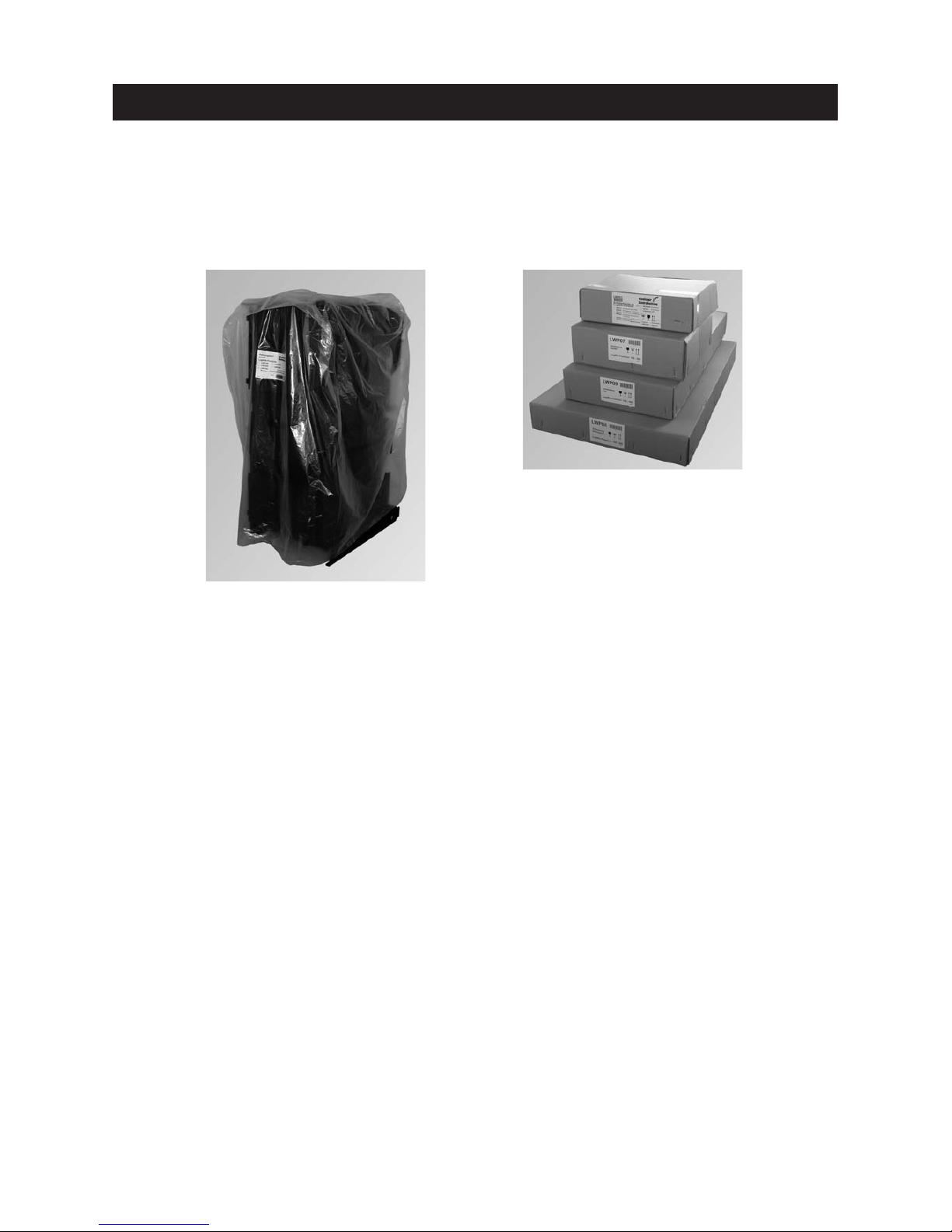
Boiler covered with a plastic sack.
The cladding, control panel and small parts can be found in the 4 cardboard boxes and in the filler chamber.
2.1.2 Optional accessories
Fitted in control panel, if ordered:
– MES system control (installed and pre-wired)
Supplied with the boiler if ordered:
– Thermal process safeguard – FK-060
– Energy-saving intake regulator
– Return hold-up group – SK RH or SK RH 54
– Motorised mixing valve, mixer groups, heating distributor
FAX 090 cleaning package comprising: vacuum cleaner, magnetic flashlight, gloves and apron
Fig. 2 LogWIN boiler 180 – 500
Fig. 3 Cladding and control panel in 4 cardboard boxes.
In the filling chamber:
– Instruction booklets
– Screws and small part
– Top insulation
– Air control
– Connecting bracket cladding
(for LWP 360 – 500 only)
– Hanger
– Cleaning tools
– Ash pan
In cardboard box no. 1 (LWP03):
– Control panel complete
– InfoWIN (display/operating module)
In cardboard box no. 2 (LWP06):
– Side panel left
– Side panel right
In cardboard box no. 3 (LWP09/LWP10):
– Insulation flue outlet
– Rear wall top
– Rear wall bottom
– Hook-in plate ash pan
– Lever for cleaning heating surfaces
– Cladding door
– Cover for cladding door switch
In cardboard box no. 4 (LWP07/LWP08):
– Cladding door cover
– Front boiler cover
– Rear boiler cover
Page 5

5
For the Installer
2.2 Taking into the building and installing
The appliance must be taken into the building and installed without subjecting it to significant knocks and jolts,
in order to avoid damaging the combustion chamber and/or the parts slipping. The warranty will be invalidated if the appliance is damaged due to having been taken into the building and installed incorrectly or if the appliance malfunctions as a consequence of this.
2.2.1 Taking into the boiler room/installation room
The LogWIN may only be transported upright and without cladding and it is easiest to transport using a lift truck
or by rolling on pipes. There is a crane lug on the top of the boiler for transport using hoisting winches. When
transporting via stairs and the such like, the boiler must be suitably secured. Also refer to the technical data in
section 4.4 for transport dimensions.
Tip:: The weight can be reduced by approx. 130 kg by removing parts which are easy to disassemble (e.g. doors,
hook-in plates, burnthrough plates, heating surface cleaning etc.).
2.2.2 Installing in the boiler room/installation room
The boiler can be installed directly on a non-flammable surface and does not require special foundations.
2.2.3 Note before connection
Move the boiler to its definitive installation position and use the set screws to align it inclined slightly upwards
towards the rear.
Tip: Before connecting the heating system, install the insulation, flue outlets and rear wall – see section 2.5.
Please note:
– The minimum clearances for connections, cleaning and maintenance should be observed – see section 2.2.4.
– Set up the boiler only in a dry area.
– Follow local regulations and guidelines regarding the boiler room/installation room.
– Sufficient ventilation of the set-up area must be assured.
Air consumption: LWP 18 kW: approx. 40 m
3
/h
LWP 25 kW: approx. 55 m
3
/h
LWP 30 kW: approx. 70 m
3
/h
LWP 36 kW: approx. 80 m
3
/h
LWP 50 kW: approx. 110 m
3
/h
The combustion air must be free from halogens and hydrocarbons (detergents, e.g. washing
machine) otherwise malfunctions may occur.
Page 6
6
For the Installer
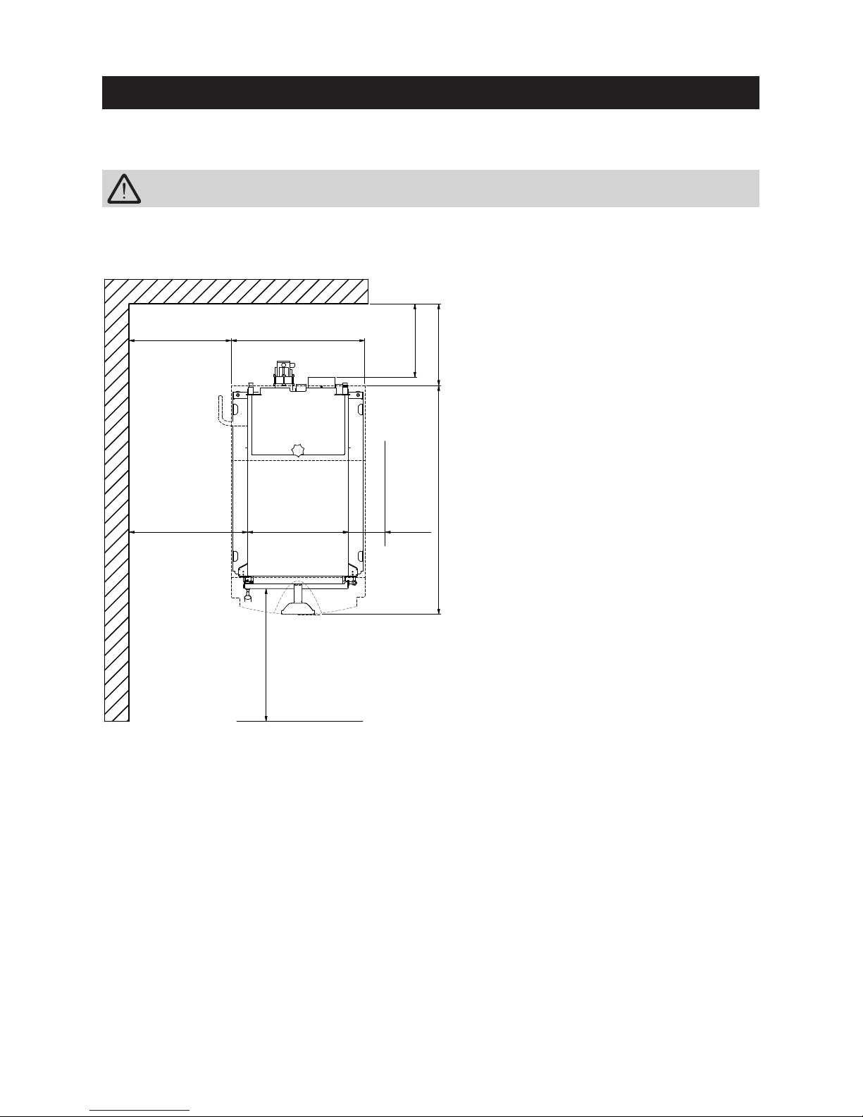
2.2.4 Minimum clearances
Fig. 4 View from above
Follow the installation guidelines for boiler room/installation room!
494
(604)
min.
580
(680)
min.
180
min.
650
(760)
min.
360
400
min.
500
(600)
654
(764)
1120
1)
Recommended minimum room heights: 1950 mm
All measurements in mm.
Details provided in brackets apply
to
LPW 360,500.
1) min 280 mm with door catch
on this side
Page 7
7
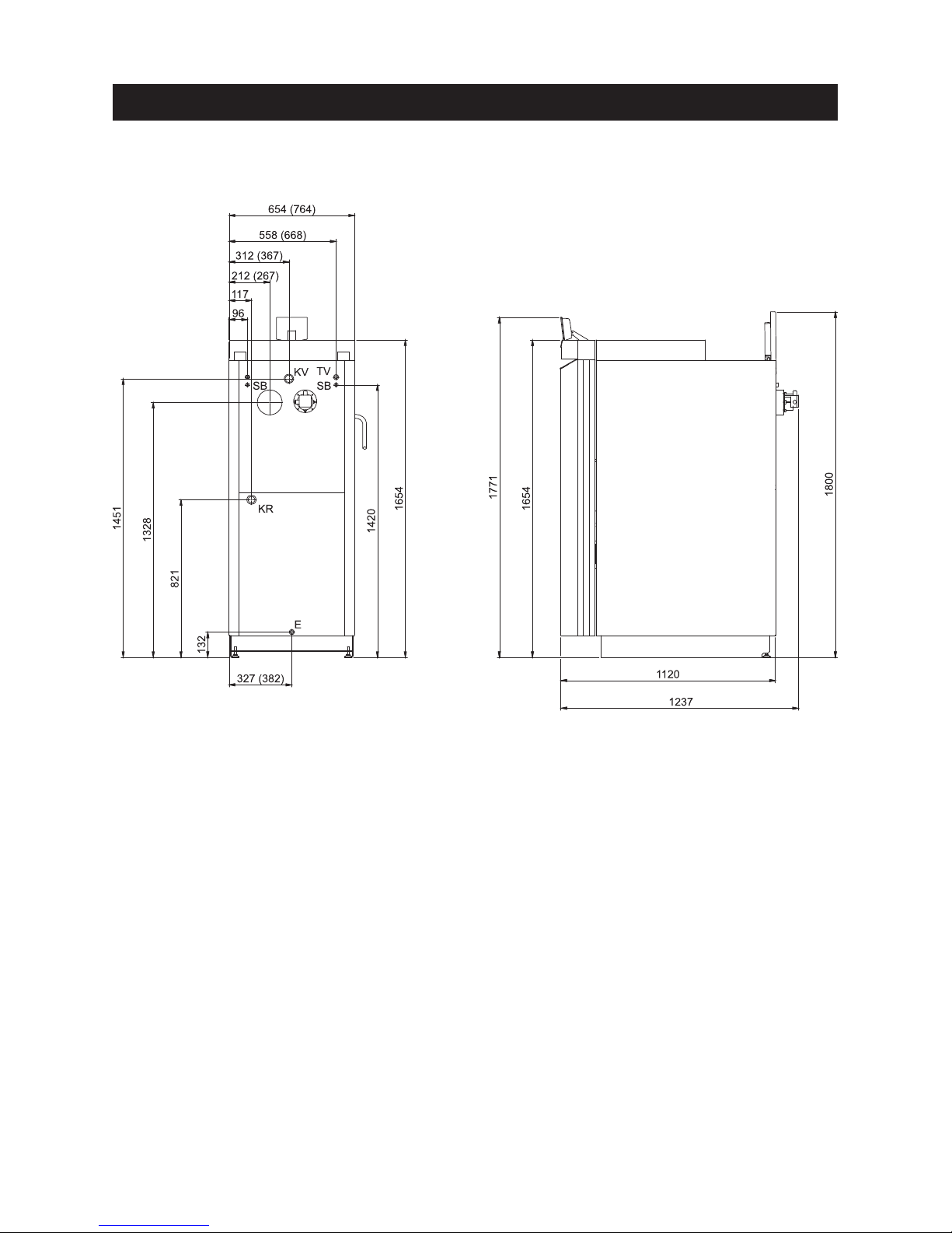
2.3 Dimensional sketches
Fig. 5 Rear view Fig. 6 Left view
KV . . . . .Boiler feed (5/4” pipe)
KR . . . . .Boiler return (5/4” pipe)
TV . . . . .Thermal valve sensor (1/2” sleeve)
SB . . . . .Thermal safety device (1/2” tube)
E . . . . .Discharge
For the Installer
2)
All dimensions in mm:
Details provided in brackets apply to
LPW 360 and 500.
2) with cleaning cover open
Page 8
8
For the Installer
2.4 System
2.4.1 Area of use
For heating buildings acc. to EN 12831.
The boilers are designed and approved as heat generators for hot water heating systems with permissible flow
temperatures of up to 90 °C.
2.4.2 Standards
The following European standard should be followed: EN 12828, this specifies that the following should be fitted:
a) A closed expansion tank.
b) A reliably functioning safety valve installed at the highest point of the boiler or at a non-closable line.
c) A thermometer, a pressure gauge.
d) An automatic device for dissipating heat which will prevent the maximum permitted operating temperature
from being exceeded. The built-in thermal safety device (heat exchanger) should always be used in conjunction with the thermal process safeguard. In addition, a gravity feed hot water tank with thermal process safeguard can also be used.
e) A low-water cut-off: A low-water cut-off is not required for systems providing up to 300 kW nominal thermal
output, if it can be assured that excess heating will not result from a lack of water in the system.
If the boiler is above the radiators, then a low-water cut-off must be installed.
2.4.3 Accumulator tank
Having a correctly sized accumulator tank is essential for correct operation of a wood-fired heating system. The
fuel must always be selected and the heat load of the building calculated. Heating characteristics (e.g. bringing
the hot water tank up to temperature in summer) and the system configuration (ground and/or radiator heating
circuits) should also be taken into consideration.
Tip: Correct amount of fuel – i.e. boiler only ¼ – ½ full at the turn of the seasons.
With domestic water supply plants, a heat dissipation of the smallest possible boiler output must
be assured even if there is a power failure! Failure to comply with this requirement can result in a
thermal overload of the boiler components and invalidation of the warranty.
Rooms that are not heated at times (guest rooms, living areas only used at weekends, etc.) must be
subtracted from the calculated heat load (Q
H
) for the accumulator tank configuration!
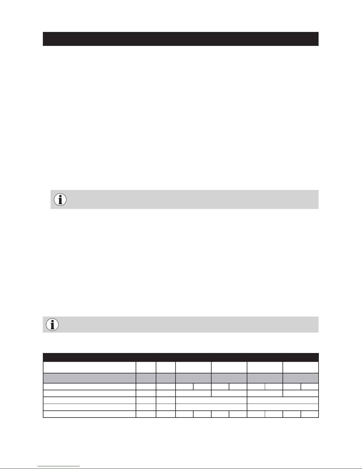
LogWIN LWP 180 LWP 250
Formula
symbol
Unit Beech fully filled
Spruce fully
filled
Beech fully filled
Spruce fully
filled
Recommended accumulator tank content: l 2000 2000 2000 2000
Heat load of the building acc. to EN 12831
Q
H
kW 13.0 17.4 13.0 17.4 13.0 25.0 13.0 25.0
Burning duration of the LogWIN at nominal thermal output
T
B
h 10.3 6.6 7. 2 4.6
Nominal thermal output of the LogWIN
Q
N
kW 17.4 25.0
Minimum thermal output of the LogWIN
Q
min
kW 13.0 13.0
Correction factor
1)
f 1.0 19 1.029 1.029 1.046 1.047 1. 15 6 1.074 1. 24 6
Recommended accumulator tank content:
Page 9
9
For the Installer
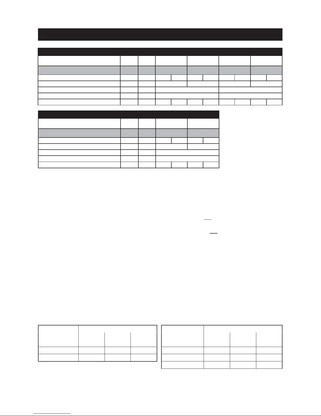
Vsp= f · 15 · TB· QN· (1 – 0.3
Q
H
)
Q
min
Vsp= 15 · TB· QN· (1 – 0.3
Q
H
)
Q
min
Vsp= 55 litres · Q
N
1)
Correction factor f (Holzenergie Schweiz quality mark): A firewood boiler must be operated at nominal output for about 1 hour after starting. Additionally,
about 0.5 hour is required for heating up. As a rule, it is not possible to operate with the lowest possible output right from the start. The correction factor f
depends on the relationship between the nominal and lowest possible output levels and is individually set for each boiler (assumption: system reaches
nominal output 1.5 hours after starting).
LogWIN LWP 500
Formula
symbol
Unit Beech fully filled
Spruce fully
filled
Recommended accumulator tank l 3000 3000
Heat load of the building acc. to EN 12831
Q
H
kW 24.0 49.9 24.0 49.9
Burning duration of the LogWIN at nominal thermal output
T
B
h 4.6 2.9
Nominal thermal output of the LogWIN
Q
N
kW 49.9
Minimum thermal output of the LogWIN
Q
min
kW 24.0
Correction factor
1)
f 1.0 72 1.280 1.11 4 1.439
Selection and combinations of accumulator tank CWK/CWK or CWK/CWP:
The accumulator tanks can be combined with one another in parallel in a flexible way. The connection set CW021 (accessory) can be used for the following tank combinations.
Klassik
Premium
CWK 700
(720 l)
CWK 1000
(1000 l)
CWK 1500
(1500 l)
CWP 800 (800 l) 1520 l – –
CWP 1000 (960 l) – 1960 l 2460 l
Klassik
Klassik
CWK 700
(720 l)
CWK 1000
(1000 l)
CWK 1500
(1500 l)
CWK 700 (720 l) 1440 l – –
CWK 1000 (1000 l) – 2000 l 2500 l
CWK 1500 (1500 l) – 2500 l 3000 l
CaloWIN Premium with CaloWIN Klassik Two CaloWIN Klassik appliances
Other combinations are also possible in series operation. In this case, the accumulator tanks must be connected by the client (no connection set is available).
LogWIN LWP 300 LWP 360
Formula
symbol
Unit Beech fully filled
Spruce fully
filled
Beech fully filled
Spruce fully
filled
Recommended accumulator tank content: l 2000 2000 2500 2500
Heat load of the building acc. to EN 12831
Q
H
kW 13,0 29,9 13.0 29.9 17.8 35.6 17.8 35.6
Burning duration of the LogWIN at nominal thermal output
T
B
h 6.0 3.8 6.3 4.1
Nominal thermal output of the LogWIN
Q
N
kW 29.9 35.6
Minimum thermal output of the LogWIN
Q
min
kW 13.0 17.8
Correction factor
1)
f 1.066 1. 36 8 1.10 3 1.579 1. 05 1 1.1 79 1.0 78 1. 27 3
Page 10

10
2.4.4 Heating circuits
Several heating circuits:
The total consumed output is not allowed to exceed the nominal thermal output of the boiler. In-line regulating
valves must be installed to permit better regulation of the system. In a building without insulation (new building, not yet plastered) the calculated and actually required heating requirements often differ to a considerable
extent.
Minimum heat consumption:
It must be possible for the smallest possible boiler output must be continuously dissipated from the boiler during operation (see technical data in section 4.4.). Alongside an accumulator tank of a sufficient size, suitable measures for minimum heat consumption (e.g. never completely closing the manual mixing valve, “consumer circuit” or radiators that cannot be blocked off, not all radiators fitted with thermostatic valves) must be guaranteed
in each phase of operation.
Having a correctly sized accumulator tank is essential for correct operation.
Mixer valve:
A 3-way mixer valve is always necessary; in conjunction with outside temperature control, there must be a 3way motorised mixing valve and an accumulator tank.
Underfloor heating:
Possible with an accumulator tank (with outside temperature control, motorised mixing valve).
Return flow temperature increase:
This is necessary in all systems with an accumulator tank and in old systems with a large volume of water (>
200 l). It is essential for the temperature of the return flow to be kept to at least 45 °C during heating, otherwise
the temperature of the return flow must be increased using a mixing pump or valve.
In order to achieve good temperature stratification in the accumulator tank, we recommend setting the boiler
circuit to a 15-20 K differential by means of the return hold-up group SK RH or SK RH 54. See the enclosed instructions for the return hold-up group for guidance values for the setting.
Boiler start-up relief:
A boiler start-up relief must be installed and connected in all cases so that the circulation pump(s) are switched
off when the boiler temperature is below 60 °C. This prevents condensation forming in the boiler and extends
its service life.
A boiler start-up relief of this kind is contained in the MES control system.
2.4.5 Heating water
a) The chemical composition of the heating water must meet the specifications of ÖNORM H 5195 Part 1 or VDE
2035 P1. According to ÖNORM M 5195 Part 1, the condition of the heating water must be checked every 2
years by a heating technician in order to avoid corrosion and sediment accumulation in the heating system.
The check must be performed once every year in heating systems with more than 1500 litres of heating water.
For the Installer
“Komfort” Pufferspeicher: Won’t open in tag editor “Comfort” accumulator tank
In this case, the size of the accumulator tank is based on the long-term heat output, i.e. how long the customer
wants to heat from the accumulator tank. The boiler output does not depend on the heating requirements of the
building, but on the filling chamber size of the boiler and how often the customer wants to replenish fuel to
bring the accumulator tank up to temperature.
A sensible precaution for a buffer solution of this kind is a low temperature heating circuit design (< 35 °C).
Page 11
11
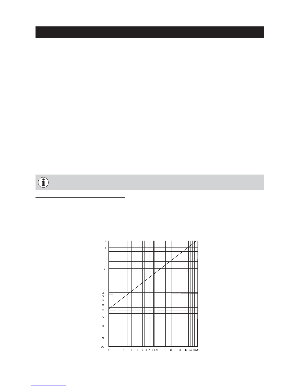
Diagram 1 water-side resistance
2.4.8 Water-side resistance (pressure loss)
Pressure loss (mbar)
Flow rate (m
3
/h)
LWP 180 – 500
For the Installer
With domestic water supply plants, a heat dissipation of the smallest possible boiler output must be
assured even if there is a power failure! Failure to comply with this requirement can result in a thermal overload of the boiler components and invalidation of the warranty.
T
echnical data of the thermal safety device:
Minimum connection pressure: 2 bar
Maximum operating pressure: 6 bar
Connection dimension: 1/2” external screw thread
2.4.6 Domestic water (bringing the hot water tank up to temperature in
summer)
There may still be fuel in the boiler after the hot water tank has been brought up to temperature. As a result,
measures must be taken to dissipate the surplus energy – see section 2.4.4 Heating circuits; Minimum heat consumption.
2.4.7 Thermal safety device (heat exchanger)
The thermal safety device is used for protection against overheating if the circulation is interrupted (e.g. power
failure) and is not allowed to be used for domestic water heating. See section 2.7 regarding installation of the
thermal process safeguard.
b) The pipe lines and heating appliances should be thoroughly rinsed before the boiler is connected.
c) To protect the boiler from contamination from the heating system, installation of a dirt trap is required in old or
existing systems (mesh size 0.5 mm) with maintenance cocks installed in the return line.
d) If oxygen diffusion or sludge build-up cannot be prevented, the system must be segregated by means of a
heat exchanger.
e) If antifreeze is used, a minimum volume of 20 % antifreeze is required, otherwise corrosion prevention is
not guaranteed.
Page 12
12
For the Installer
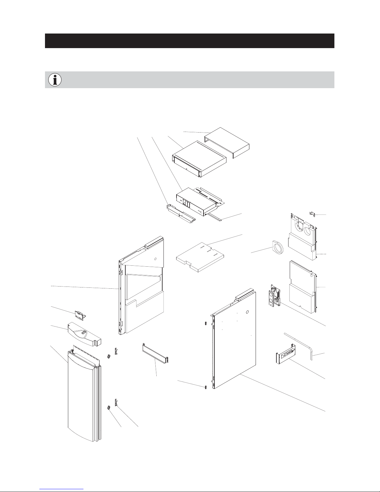
2.5 Installing the cladding
4
3
2
1
5 6 7 8
9
10
11
12
13
14
15
16
17
18
20 19
22 21
1 Cladding door
2 Cladding door cover
3 InfoWIN
4 Left side panel
5 Cover for cladding door switch
6 Control panel complete
7 Front boiler cover
8 Rear boiler cover
9 Connecting bracket cladding
(for LWP 360 – 500 only)
10 Top insulation
11 Insulation flue outlet
12 Retaining bracket for blower
plug
13 Rear wall top
14 Rear wall bottom
15 Air control
16 Lever for cleaning heating sur-
faces
17 Hanger
18 Side panel right
19 Magnetic catch (2 pcs.)
20 Hook-in plate ash pan
21 Bracket for door hinges (2 pcs.)
22 Door hinge (2 pcs.)
Fig. 7 Insulation and cladding parts
All cladding parts must be fitted in full for air guidance and the dissipation of heat on the boiler.
The cladding comprises the following parts:
Page 13
13
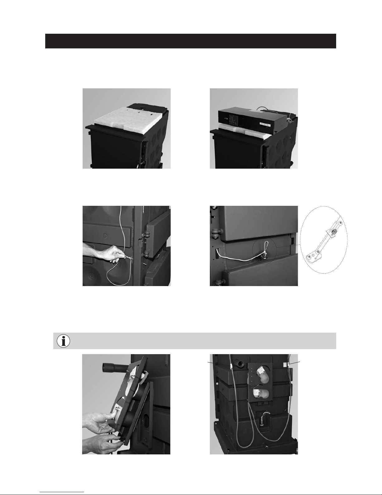
Fig. 12 Hinging in air control at top
and screwing on at bottom
Fig. 13 Using cable ties to secure cables to the
boiler at the white/yellow marks
– Fit air control on rear of boiler; hinge in air control at top and secure with screw at bottom – Fig. 12.
– Route cables from air control and lambda sensor upwards at sides and secure to the boiler at the position
of the white/yellow mark on the cable using the cable ties of the same colour – Fig. 13.
Fastening clips
with yellow mark
Fig. 11 Installing the thermocontrol sensor
For the Installer
Fig. 10 Threading through thermocontrol sensor
– Thread thermocontrol sensor (green cable) through boiler door rail – Fig. 10.
– Fit front sensor at front above ash door – Fig. 11.
The air control cables must be long enough for service purposes and must not be routed around
the connection discharge.
Fastening clips
with white
mark
Installation sequence:
– Carefully install the insulation on the top of the boiler – Fig. 8.
– Attach control panel – Fig. 9.
Fig. 8 Fitting top insulation on the boiler Fig. 9 Attaching control panel
Page 14
14
For the Installer
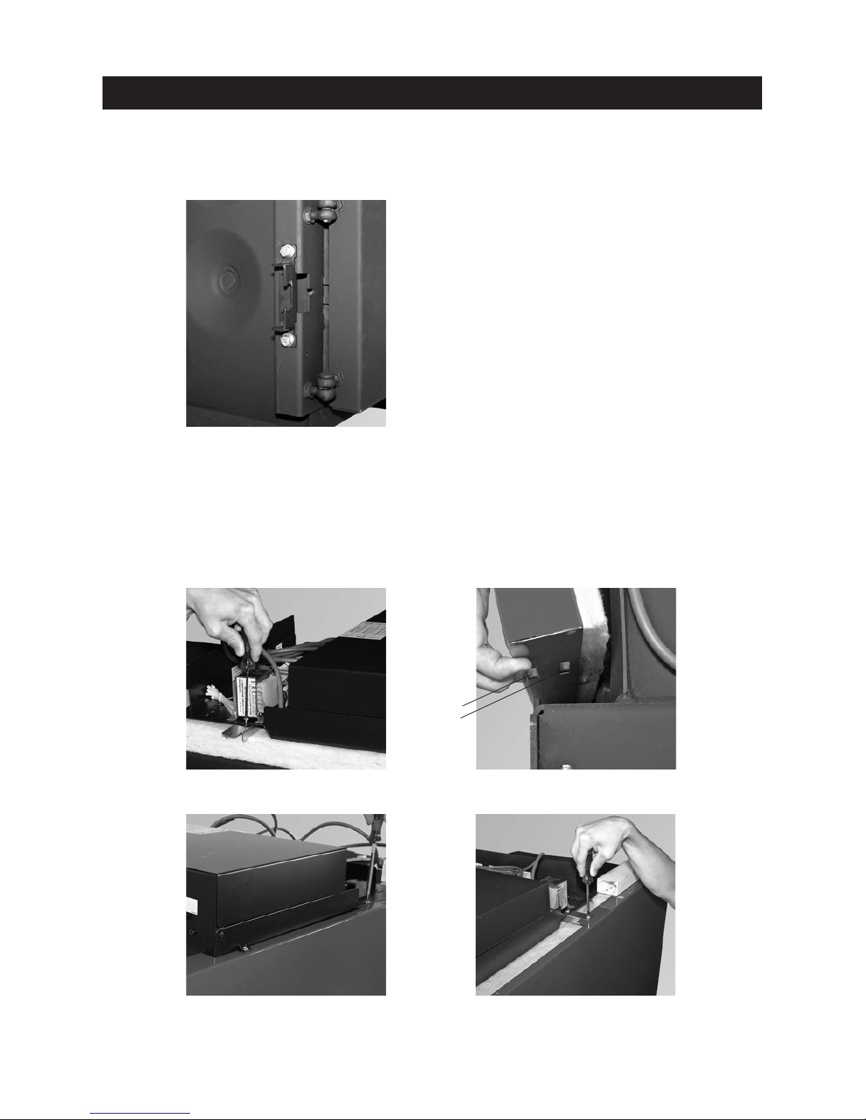
– Only for LogWIN 360 – 500: Slide connecting bracket cladding under control panel and secure to control panel
with 2 screws – Fig. 15.
– Fit side walls; depending on boiler model, at bottom adjust at base in cuttings (Fig. 18) and at top screw
onto control panel or connecting bracket – Figs. 16, 17, 18.
Fig. 17 Screwing down LogWIN 180–300 side
walls with control panel in four places
Fig. 16 Hooking in side panels at the bot-
tom
Fig. 18 Screwing down LogWIN 360, 500 side walls
with connecting bracket in two places
Fig. 15 Sliding connecting bracket under control
panel and screwing on in two places
– Screw both brackets for the cladding door hinges (different hole spacing) onto the boiler door rail at the top
and bottom – Fig. 14.
Note:The brackets for the cladding door can either be screwed on for a door catch on the left or right.
Cutting for LWP
180–300
LWP 360, 500
Fig. 14 Fitting brackets for door hinge
Page 15
15
For the Installer
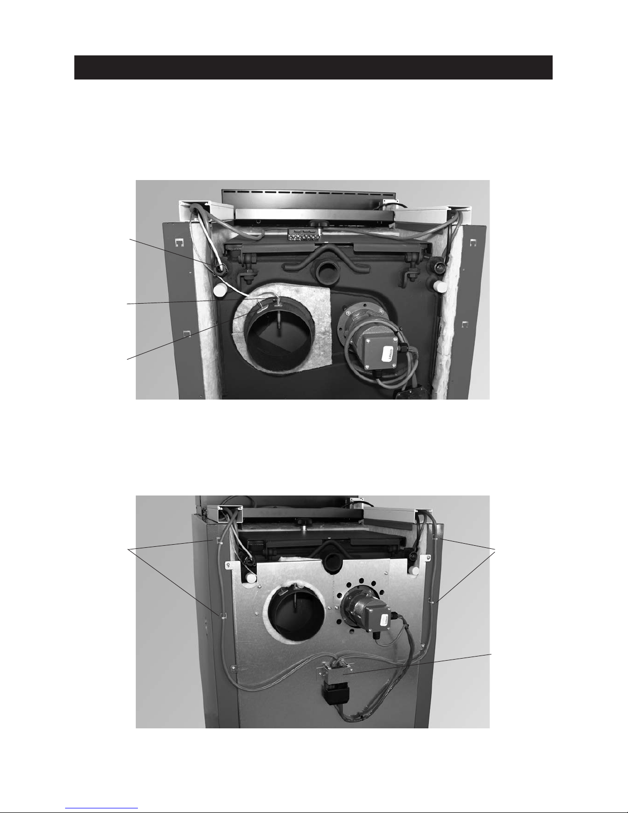
– Secure top rear wall to side walls with 6 screws – Fig. 20.
– Screw retaining bracket for blower plug onto rear wall with plug, route cable laterally in cable ducts, insert
blower motor plug and secure cable at side with cable ties – Fig. 20.
– Screw on rear wall at bottom in 5 places (no diagram).
Fig. 19 Fitting flue outlet insulation; inserting boiler and safety temperature limiter sensor in immersion sleeve
and securing with sensor guard; inserting flue gas temperature sensor in flue outlet and securing with
– Fit insulation for flue outlet – Fig. 19.
– Route boiler, safety temperature limiter and flue gas temperature sensor towards the rear from the control
panel in the cable duct on the flue tube side. Insert boiler sensor and safety temperature limiter sensor as
far as possible into the immersion sleeve and secure them with the sensor guard to prevent them from slipping out – Fig. 19.
– Insert flue gas temperature sensor (metallic, braided cable) in the protective tube in the flue outlet and secure
with lateral screw to prevent it from slipping out – Fig. 19.
Fig. 20 Fitting rear wall, screwing retaining plate onto rear wall at top with blower plug, securing cable at
side with cable ties
Securing cable
with cable ties
Securing cable
with cable ties
Retaining plate for
blower plug
Boiler and
safety temperature limiter
Flue gas temperature sensor
(metallic,
braided cable)
Measuring
opening
Page 16
16
For the Installer
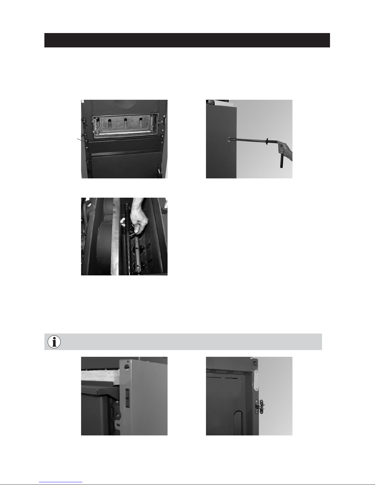
Fig. 22 Punching through the cut-out, inserting lever
for cleaning heating surfaces through opening
Fig. 23 Sliding lever through axle and secur-
ing with screw (inserted only)
Fig. 24 Punching through 2 cut-outs for magnetic
catches and pushing in catch
Fig. 25 Punching through 2 cut-outs for door
hinge and screwing on door hinge
Fig. 21 Screwing on hook-in plate ash pan with 4
TT self-tapping screws
– Screw hook-in plate ash pan on between lighting and ash doors with 4 TT self-tapping screws – Fig. 21.
– Depending on accessibility, either fit lever for cleaning heating surfaces on the left or right side. Punch through
the cut-out, insert lever through opening in side wall and slide inwards through the cleaning heating surfaces axle and secure with screws (inserted only) – Figs. 22, 23.
– Punch through 2 cut-outs for magnetic catches at top/bottom from side wall and push in catch – Fig. 24.
– Punch through 2 cut-outs for door hinge at top/bottom from cladding door and screw on door hinge – Fig. 25.
Hook-in plate
ash pan
Punch through for the door hinge on the door catch side chosen. Punch through for magnetic catches on the opposite side.
Page 17
17
For the Installer
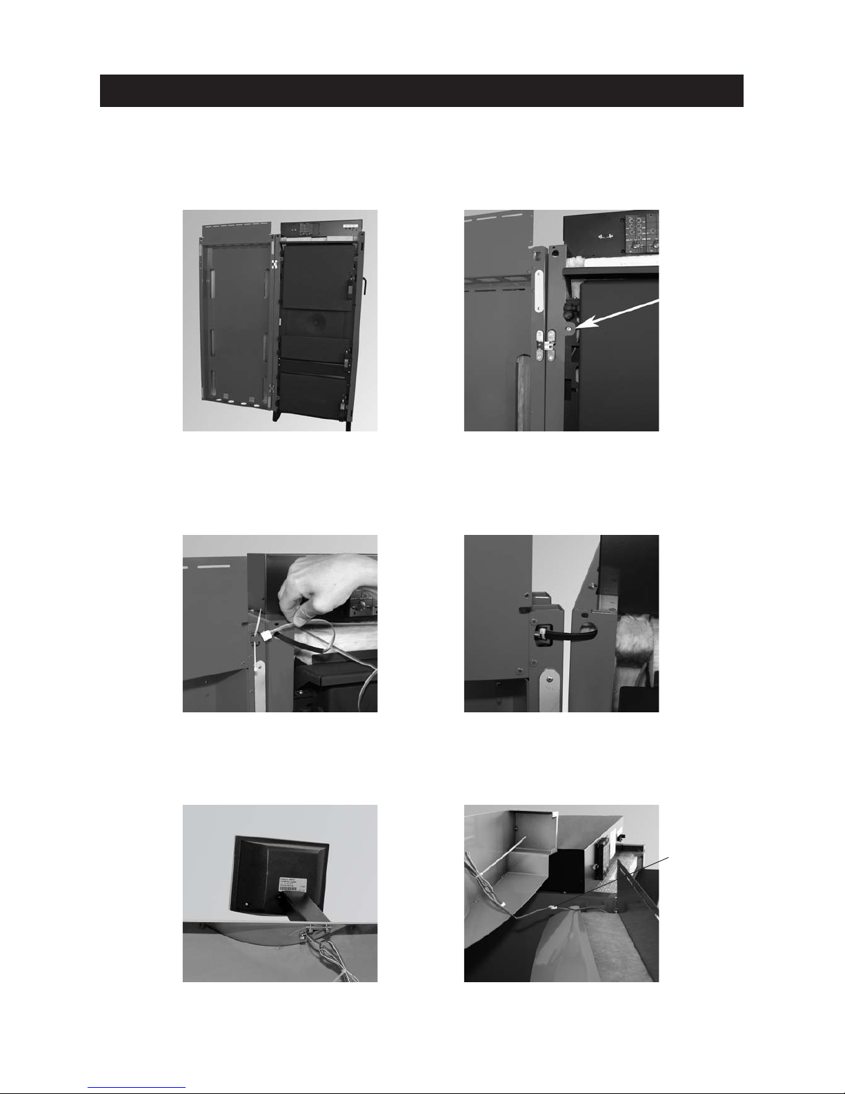
Fig. 26 Mounting the cladding door. Fig. 27 Straightening side walls
Fig. 31 Connecting InfoWIN cables
Fig. 28 Threading in InfoWIN cable
– Punch through 2 cut-outs for door hinge at top/bottom from side wall and screw on cladding door – Fig. 26.
– Straighten the side walls by eye using the width of the cladding door and screw down at front bottom/top
using 4 TT self-tapping screws – Fig. 27.
– Thread cable for Info-WIN from the control panel, sideways through the opening in the side wall and cladding
door – Fig. 28. Cable protection must be in position at the transition between the side wall and door. Use
cable ties to secure cable to the door – Fig. 29.
– Screw InfoWIN onto cladding door cover – Fig. 30.
– Connect InfoWIN cable with control panel cable – Fig. 31.
Fig. 29 Securing InfoWIN cable with cable
ties at cable protection
Fig. 30 Screwing InfoWIN onto cladding door
cover
Connecting
cables
Page 18
18
For the Installer
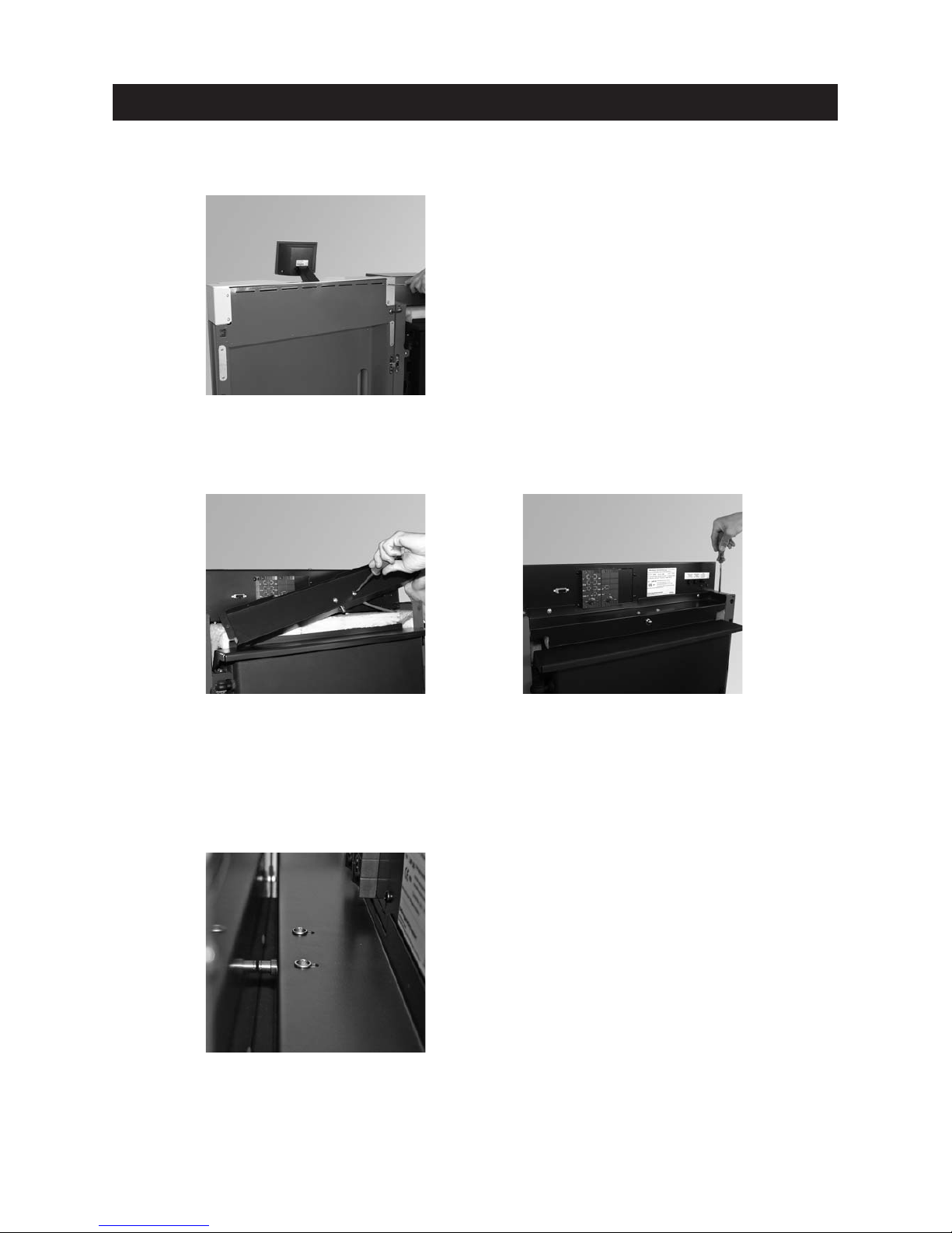
Attach cladding door cover to cladding door and use 4 screws to secure – Fig. 32.
Fig. 32 Securing cladding door cover in 4 places
Fig. 33 Screwing cladding door switch in
cover
Fig. 34 Fitting cover
Fig. 35 Setting cladding door switch
Secure cladding door switch in cladding door switch cover with 2 screws – Fig. 33.
– Screw cladding door switch cover on side walls (2 x) and control panel (2 x) – Fig. 34.
– When closing the cladding door, the cladding door switch must be set such that there is still sufficient shift-
ing travel after switching (audible clicking) before the cladding door is totally closed. If necessary, use screwdriver to reset – Fig. 35.
Page 19
19
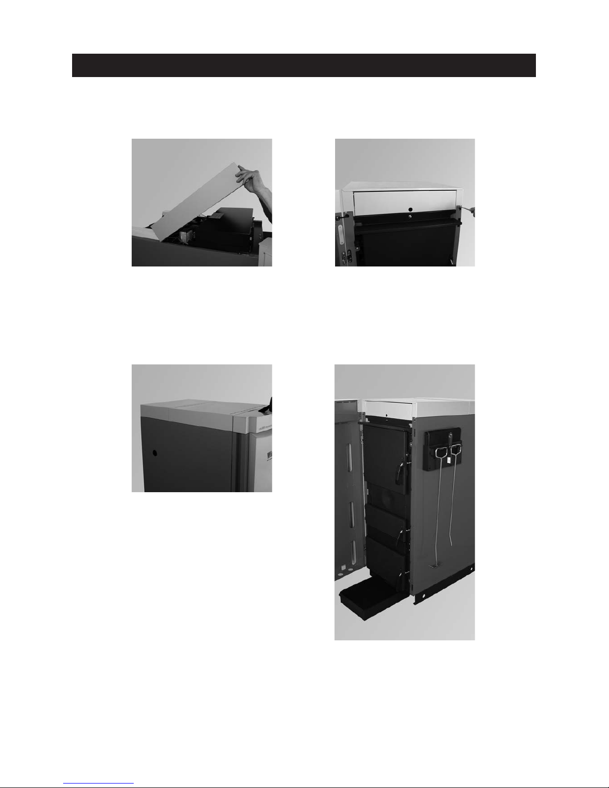
– Insert the pins on the rear boiler cover into the holes provided in the side panel cladding – Fig. 38.
– Install the hanger with the instructions folder, cleaning and operating implements on a side panel of the boil-
er (Fig. 39) or on a wall in the boiler room/installation room.
– Keep ash pan under boiler.
For the Installer
Fig. 36 Hinging in boiler cover Fig. 37 Securing boiler cover in 2 places
Fig. 38 Putting on the rear boiler cover
Fig. 39 Fitting hanger, ash pan under boiler
– Hinge in front boiler cover (Fig. 36) and secure to side walls at front using 2 screws – Fig. 37.
Supplied as standard:
– Folder containing instructions
– Poker
– Scratcher
– Cleaning brush
– Spatula
– Ash pan
– Hanger (for installation on the wall or LogWIN
side panel)
Page 20
20
For the Installer
1
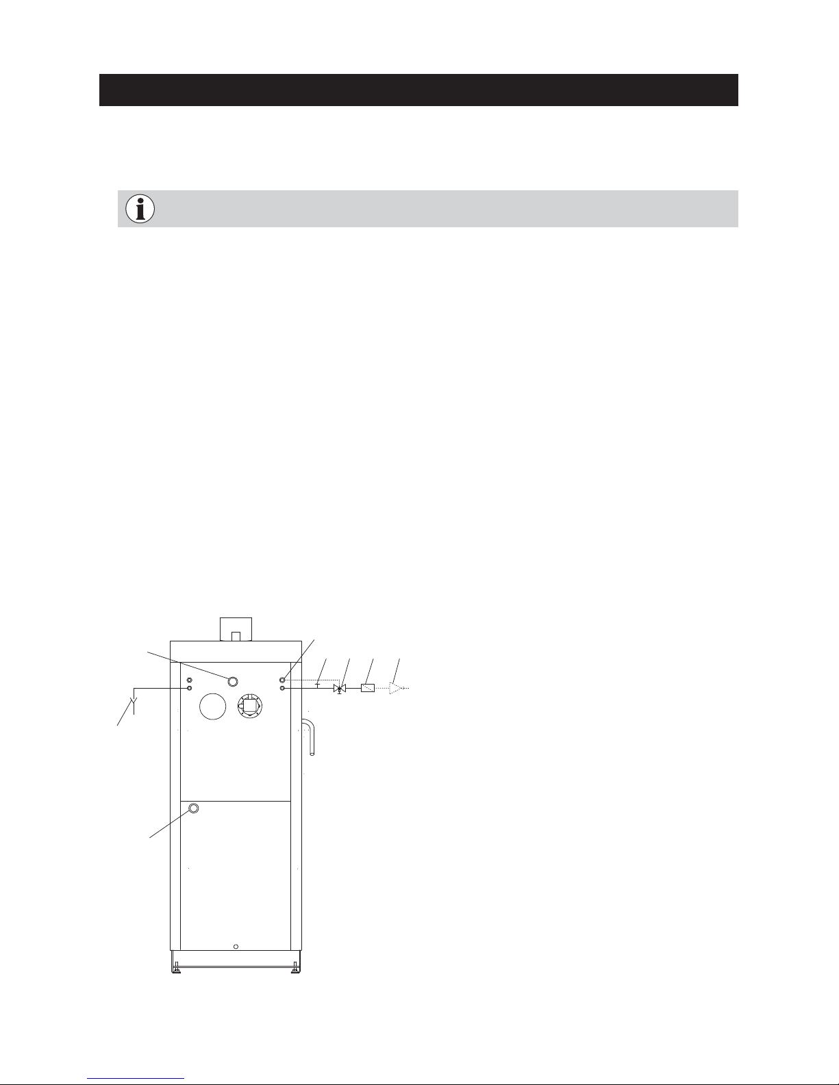
2.7 Installing the thermal process safeguard
a) The thermal process safeguard and cleaning T-piece must still be accessible after installation.
b) The drain must be visible in order to check the function, therefore use a discharge funnel.
Fig. 40 Thermal safety device connection
8
7
6
4 3 2 1
5
Minimum connection pressure of the thermal
safety device: 2 bar.
It must not be possible to block the connection manually.
1 Pressure reducing valve (only with CW connec-
tion
of more than 6 bar)
2 Dirt trap
3 Thermal process safeguard
(opens at approx. 95 °C)
4 Cleaning T-piece
5 Discharge funnel
6 Immersion sleeve for the sensor of the
thermal process safeguard
7 Boiler return
8 Boiler feed
Connection according to EN 303-5:
2.6 Installing the exhaust pipe
a) Install the exhaust pipe upward to the flue (45° is the ideal angle). Maximum exhaust pipe length to flue 3 m.
b) Avoid 90° bends, 45° bends are better
c) Do not push the exhaust pipe too far into the flue.
d) Do not seal the exhaust pipe completely into the flue. Connection with flexible exhaust pipe inlet into the
flue. The vacuum fan can cause sound transmissions that create noise pollution.
e) The entire exhaust line should be sealed (incl. cleaning aperture) because there can be positive pressure in
the exhaust pipe for a short period during the starting phase.
f) Insulate the exhaust pipe with at least 30 mm insulation!
c) A draught limiter is needed if the maximum draught (see technical data in section 4.4.) is exceeded during
operation.
Note: We would recommend fitting outside the flue around ½ m below where the exhaust pipe intersects
with the flue.
Any section of this exhaust line that only rises slightly (up to 30°) or is horizontal is not allowed to
be more than 1 m in length.
Page 21

21
2.8 Storing the instruction booklets
Store all the instruction booklets carefully. The best place is in the folder provided in the hanger – Fig. 39.
For the Installer
2.9 Initial start-up and operating instructions
Windhager Customer Service or the customer service partner will start up the boiler first of all, and will familiarise the customer with the system operation and cleaning of the boiler, with reference to the Operating Manual.
Please note: Do not heat up first – Start-up and maintenance are part of the guarantee requirements of the “warranty conditions”.
The following preconditions must be met before you order the initial start-up:
1.) Boiler installed correctly.
2.) System fully wired up electrically.
3.) System rinsed, filled and sufficient heat consumption must be possible.
4.) Boiler connected to domestic water and filled.
5.) Sufficient quantity of fuel available (pellets, oil, gas, slit logs).
6.) The customer must be present during start-up.
The initial start-up cannot be carried out if any one of these points is neglected. The customer will be charged
for any unnecessary costs arising as a result.
Page 22
22
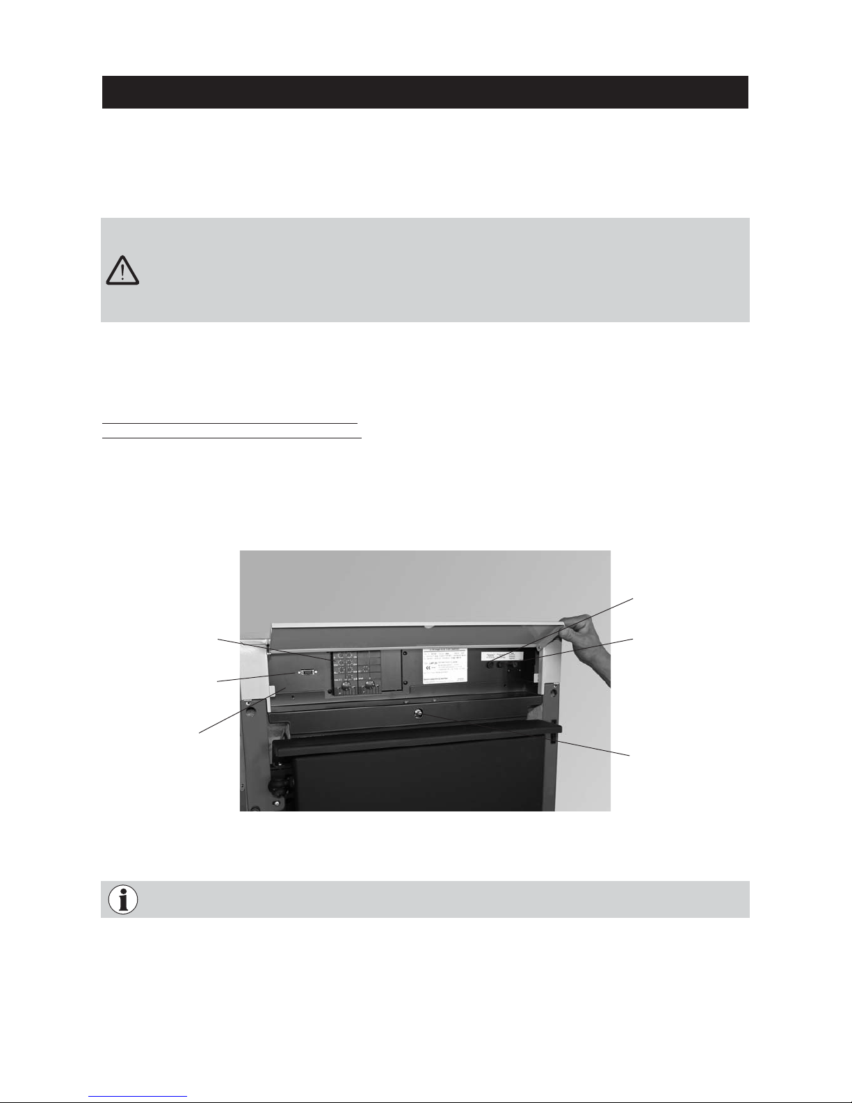
All electrical connections are located in the control panel. The control panel at the front contains the LogWIN
main board while the control panel at the rear contains the connection terminals (screwless spring-type terminals) for connecting the MES control.
– The phases of the 230 V electrical power supply must be connected correctly, otherwise the blower
might still be live even after the mains fuse has blown.
– The mains connection must be protected against short circuit with a 13 A delayed-action fuse.
– On site, the technician must install an all-pole disconnection with at least 3 mm contact gap at the
mains access point. Current-operated r.c.d. protection switches are considered all-pole disconnec-
tions (ÖVE regulation).
Fig. 41 Control panel
Fuse F1
T 6.3 A
Control panel
MES module
For the Electrician
3.1 Electrical connections
The boiler and related accessories are designed to be installed only in dry areas (protection type IP 10).
Installation of electrical components may only be performed by a qualified technician. The regulations and specifications of ÖVE, VDE, SEV and local ordinances must be followed.
We recommend using fine-wire PVC sheathed cables, e.g., H05VV-F (YMM-J) with a 3 x 1.5 mm2nominal crosssection.
The boiler is pre-wired and internally fused with a T 6.3 A fine-wire fuse to protect against short circuit – Fig.
41. By special order, the MES modules (including boiler sensor) will be installed and wired at the factory:
Maximum MES module switc
hing capacity:
Relay outputs: 230 V AC, 6 A (2 A inductive), 50 Hz
WVF and solar modules with X1/X2 contact:
Solid-state relay: 230 V AC, 1 A
The electrical rating is dependent upon the number of modules installed in the unit, that is, the number of actuators powered (pumps, mixing valves, etc.).
In areas with increased power surge risk (e.g., lightning strikes in regions prone to storms), we recommend
installation of an appropriate surge protector.
Electrical cables must not touch heating and exhaust pipes, nor must they come in contact with noninsulated boiler components. They are to be sufficiently braced and provided with a protective tube.
Cladding door switch
Fuse F2
T 2.0 A
Service plug
Page 23
23
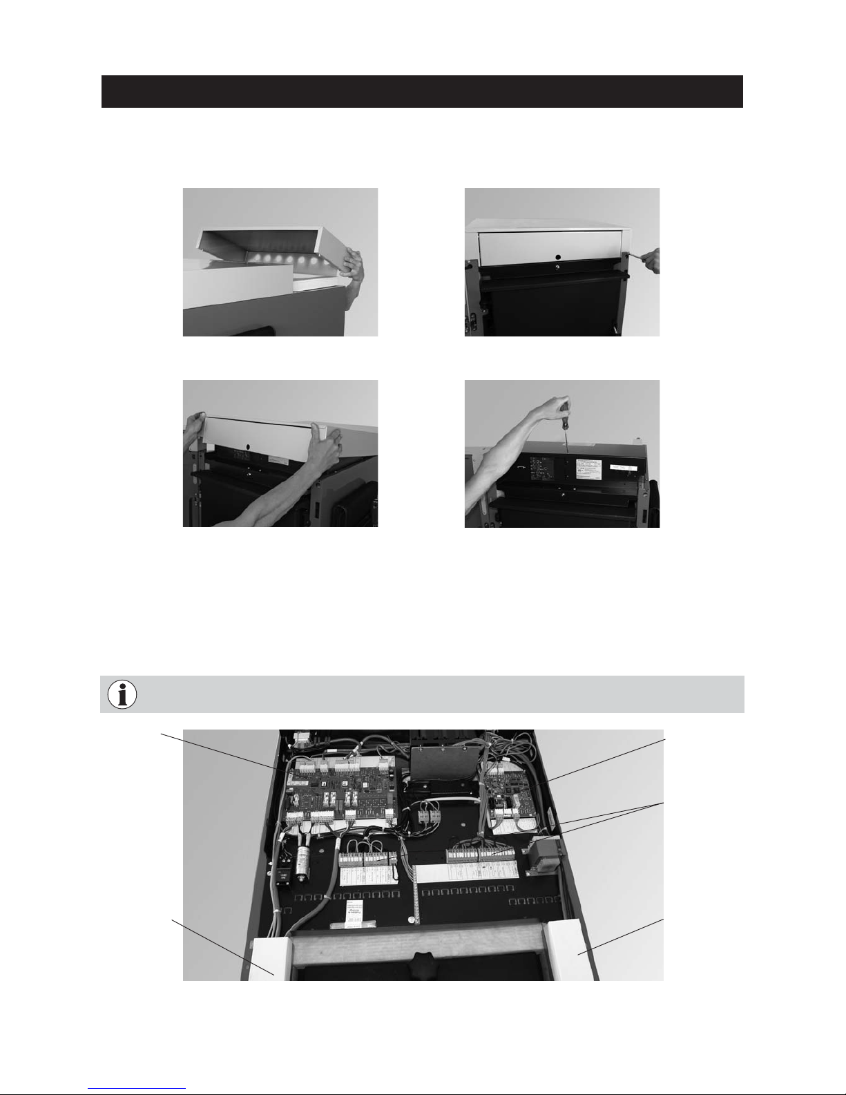
Be sure to note the separate wiring of the extra-low voltage line (sensor) and low-voltage line
(230 V AC)! Route cables in the cable ducts available – Fig. 46.
Cable duct
Low-voltage
(230 V AC)
– In the control panel, fit the plugs for the lambda sensor and air control to the extra PCB or automatic firing
devices. Cables and plugs are inscribed – Fig. 48.
– The connections for the MES system control are on the terminal blocks (screwless spring-type terminals) at
the rear in the control panel and should be connected with fine-wire PVC sheathed cables – Fig. 46.
Fig. 45 Loosening 1 screw at top and
removing the control panel cover
For the Electrician
Fig. 43 Loosening 2 screws at front
Fig. 44 Lifting boiler cover at front and
pulling off to the front
– Take off boiler cover at rear (Fig. 42), loosen 2 screws from boiler cover at front (Fig. 43) and lift up cover
and pull off to the front – Fig. 46.
– Loosen 1 screw on top of control panel cover and take off cover – Fig. 47.
Fig. 46 Control panel open, connecting plugs – rear view
Cable duct
Extra-low voltage
(sensor)
Fig. 42 Removing the rear boiler cover
Automatic firing device
(main board)
Extra PCB
MES terminal
blocks
Page 24
24
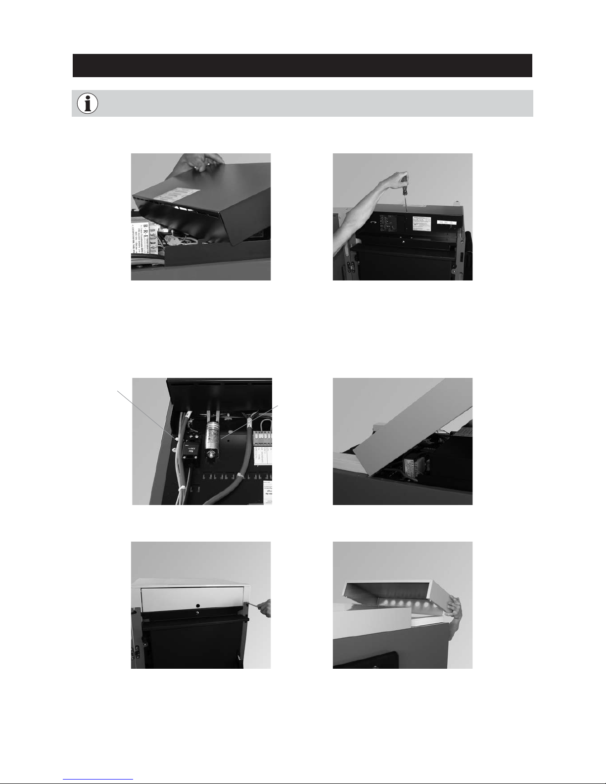
– After connecting the cables, hinge the control panel cover back in (Fig. 47), close and secure with 1 screw at
the front – Fig. 48.
For the Electrician
Electrical cables should be routed in the cable ducts intended for this purpose and are not allowed to
be routed over the cleaning cover. The space above the cover must be accessible for cleaning.
Fig. 49 Connecting plugs – rear view
Fig. 52 Putting on the rear boiler cover
Power plug
Fig. 47 Hinging in control panel cover
Fig. 50 Hinging in boiler cover
Fig. 48 Securing control panel cover
with 1 screw at the front
Fig. 51 Securing 2 screws at the front
– Connect the mains power plug at the rear of the control panel – Fig. 49
– Hinge in front boiler cover (Fig. 50) and secure at front again using 2 screws – Fig. 51.
– Insert the pins on the rear boiler cover into the holes provided in the side panel on the boiler – Fig. 52.
Page 25
25
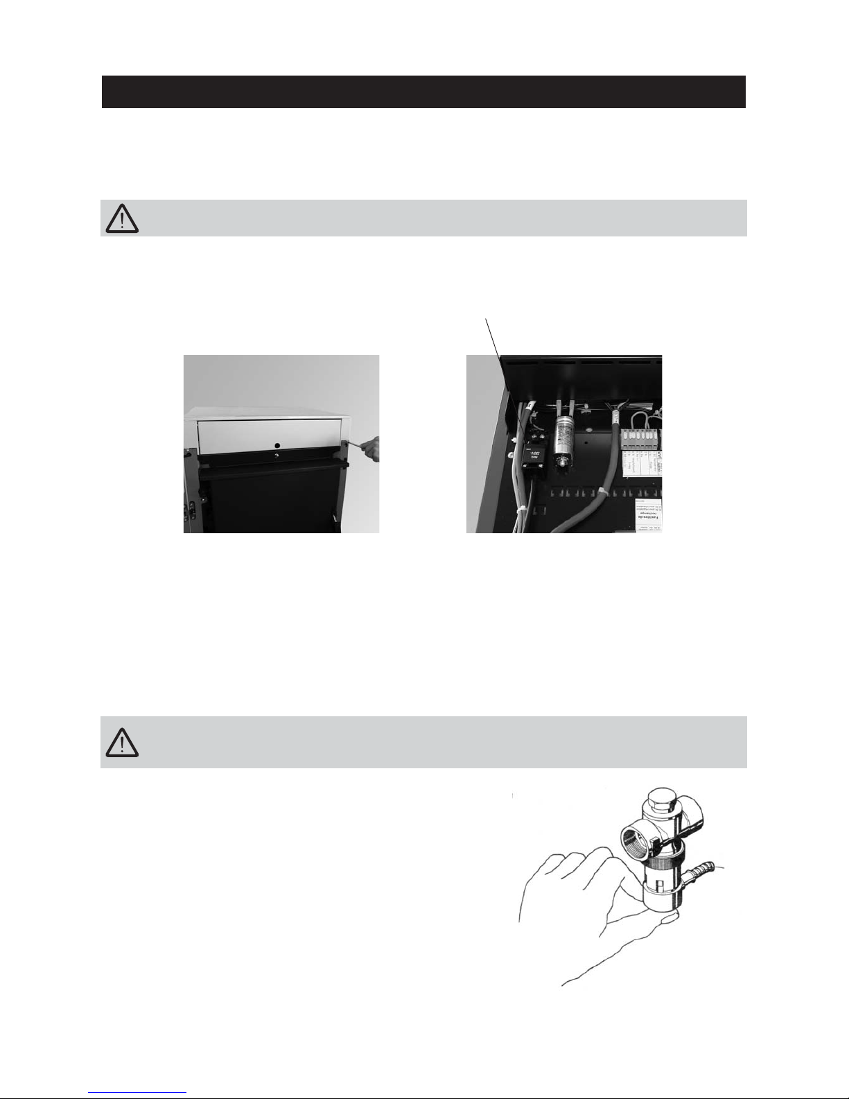
The function of the thermal process safeguard must be checked once a year by a technician and the
amount of limescale in the thermal safety device must be checked. If there is limescale in the thermal
safety device then it must always be removed.
– Press the red cap against the valve (Fig. 55) > Water must flow out
into the funnel.
– Little outflow at funnel > Limescale in thermal safety device (pump
limescale remove – e.g. formic acid – through the thermal safety
device).
– Thermal process safeguard dripping > Clean the seal on the piston
and valve seat. If the seal is damaged > Renew the piston.
Please note: There is no need to remove the fitting for this pur-
pose!
Fig. 55 Thermal process safeguard
4.2 Checking and servicing the thermal process safeguard
(Please inform your customer)
For the Service Technician
4.1 Service and repair work
Service and repair may be performed only by appropriately qualified technicians.
Switching off the on/off button on the InfoWIN does not mean the boiler and its accessories are completely
without power! When replacing system components (pumps, mixing valves, etc.) prevent all power input (e.g.
by removing the mains power plug).
Power plug
De-energise the boiler before opening the control panel for service or repair purposes. Unscrew boiler
cover at front – Fig. 53. Unplug power plug – Fig. 54.
Fig. 54 Disconnecting plugs – rear view
Fig. 53 Securing 2 screws at the front
Page 26
26
For the Service Technician
LogWIN wood gasification
boiler
Unit
LWP
180
LWP
250
LWP
300
LPW
360
LPW
500
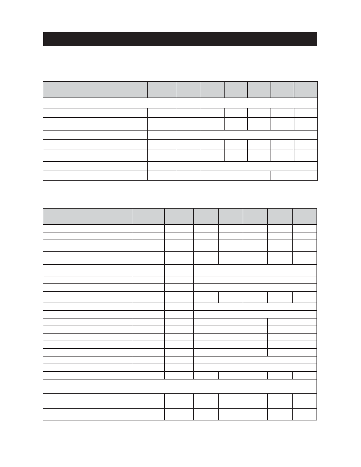
Boiler class according to EN 303-5 3 3 3 3 3
Nominal thermal output range kW 13.0–17.4 13.0–25.0 13.0–29.9 17.8–35.6 24.0–49.9
Burn duration at rated load/part load
Beech
Spruce
h
10.3/13.8
6.6/8.8
7.2/13.8
4.6/8.8
6.0/13.8
3.8/8.8
6.3/14.6
4.1/8.2
4.6/9.6
2.9/6.0
Filling chamber
Beech/spruce
l
kg
176
50/32
176
50/32
176
50/32
226
64/40
226
64/40
Feed pressure during operation (draught
requirement)
Necessary
Maximum
mbar
0.10
0.20
Boiler temperature control range °C 60–87
Return temperature min. °C 45
Water-side resistance
ΔT = 20 K
ΔT = 10 K
mbar
2.1
7. 2
3.4
14.0
5.5
20.0
7. 2
37.5
14.0
50.0
Operating pressure max. bar 3
Test pressure bar 4.5
Boiler water volume l 127 147
Weight of boiler (net) kg 580 655
Minimum transport weight
1)
kg 463 519
Installation dimensions (W x D x H) mm
640 x 1200 x 1560 695 x 1200 x 1560
Minimum installation dimensions 2)(W x D x H) mm
640 x 1020 x 1520 695 x 1020 x 1520
Filling door dimensions (W x H) mm 430 x 397
Filling chamber depth mm 562
Electrical power consumption W 47 53 58 60 66
Values from type test with beech
Testing office TÜV SÜD Munich, test report no.: 1240-00/08
Firing efficiency (100-qA)
%
95.2 94.6 94.0 93.4 91.6
Boiler efficiency
%
91.5 91.8 92.0 90.8 90.1
Flue gas temperature
rated load
part load
°C
105
97
126
97
143
97
146
94
175
109
4.3 Technical data for calculating the flue
gas system acc. to EN 13384-1
LogWIN wood gasification boiler
Formula
symbols
Unit
LWP
180
LWP
250
LWP
300
LPW
360
LPW
500
Values in practical operation
Nominal thermal output Q kW 17.4 25.0 29.9 35.6 49.9
Nominal heat load
(firing thermal output)
Q
N
kW 19.0 27.2 32.5 39.2 55.4
Volume concentration of CO
2
σ (CO2)
% 15
Flue gas mass flow rate at nominal output
.
m
kg/s 0.0102 0.0146 0.0174 0.0210 0.0296
Flue gas temperature at nominal output
(Average between two cleaning intervals)
T
W
°C 145 160 170 160 190
Necessary feed pressure
P
W
Pa 10
Flue gas connection diameter mm 130 150
4.4 Technical data – General
1)
by removing parts which are easy to disassemble (e.g. doors, hook-in plates, burnthrough plates, heating surface cleaning etc.).
2)
not including doors and blower motor
Page 27
27
For the Service Technician
4.5 Service level
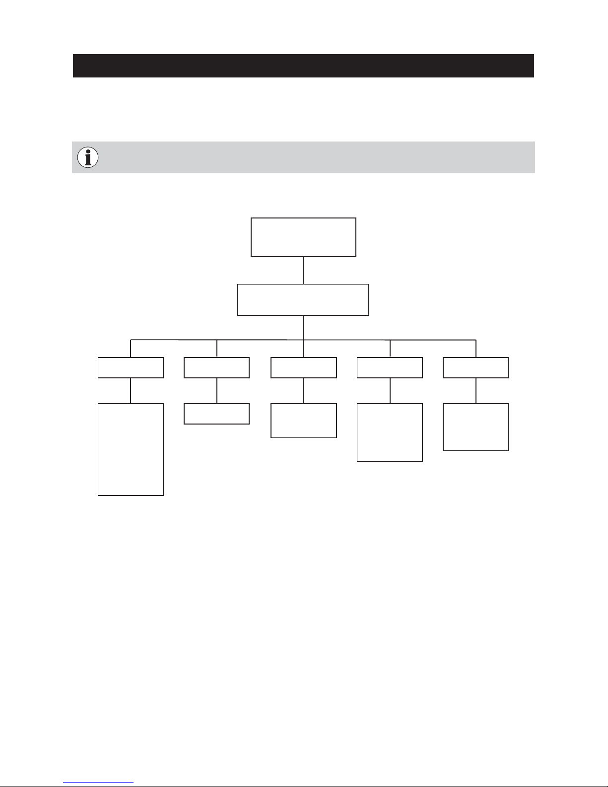
Values, restart temperature, burnout, language and actuator test can be displayed and modified on the Service
level.
Structure on the Service level:
Only trained service personnel may perform system modifications on the Service level.
Service level
Reserved for trained service
personnel only.
Menu
automatic detection
normal
Embers maintenance
Burnout
Language
Deutsch
English
Française
Italiano
Castellano
Induced draught fan
Primary airflap
Secondary airflap
O2 heating
Actuator test
Temp. Boiler
Temp. chamb.
Fan speed
Pos. Prim. airfl.
Pos. Sec. airfl.
O2 signal
O2 heat current
Temp. Exhaust
Values
Restart
temperature
Boiler temperature
for restart
Page 28
28
Values
Restart temperature
Burnout
Language
Actuator test
Choose Back
For the Service Technician
Fig. 58
Fig. 59
Service level
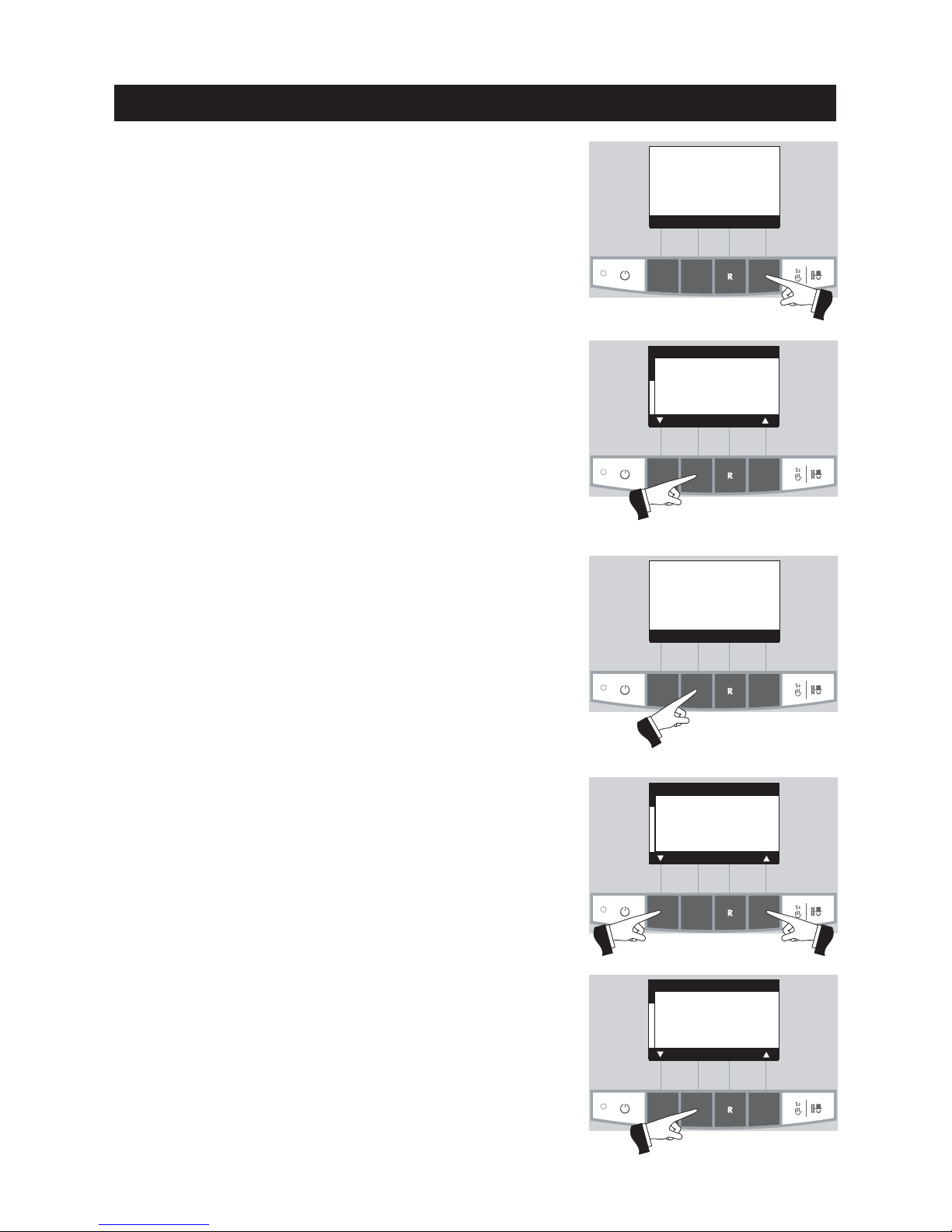
Press the
Menu
button (Fig. 58), the display shows “Service level”
– Fig. 59.
Fig. 60
Fig. 62
Confirm “Service level” by pressing the
Choose
button – Fig. 59.
Press the
5sec
. button for longer than 5 seconds – Fig. 60.
The menu item or sub-menu item is exited by pressing the
Back
button or after a delay of 45 seconds.
Use the
arrow
buttons to select the “Values”, “Restart temperature”
or “Actuator test” parameters (Fig. 61) and confirm with the
Choose
button – Fig. 62.
Fig. 61
Press for 5
seconds
Boiler temperature
(Operating phases)
Info Menu
42
°C
Service level only
for trained
service personnel
5 s
Service level
Choose Back
Values
Restart temperature
Burnout
Language
Actuator test
Choose Back
Page 29
29
For the Service Technician
4.5.1 Values
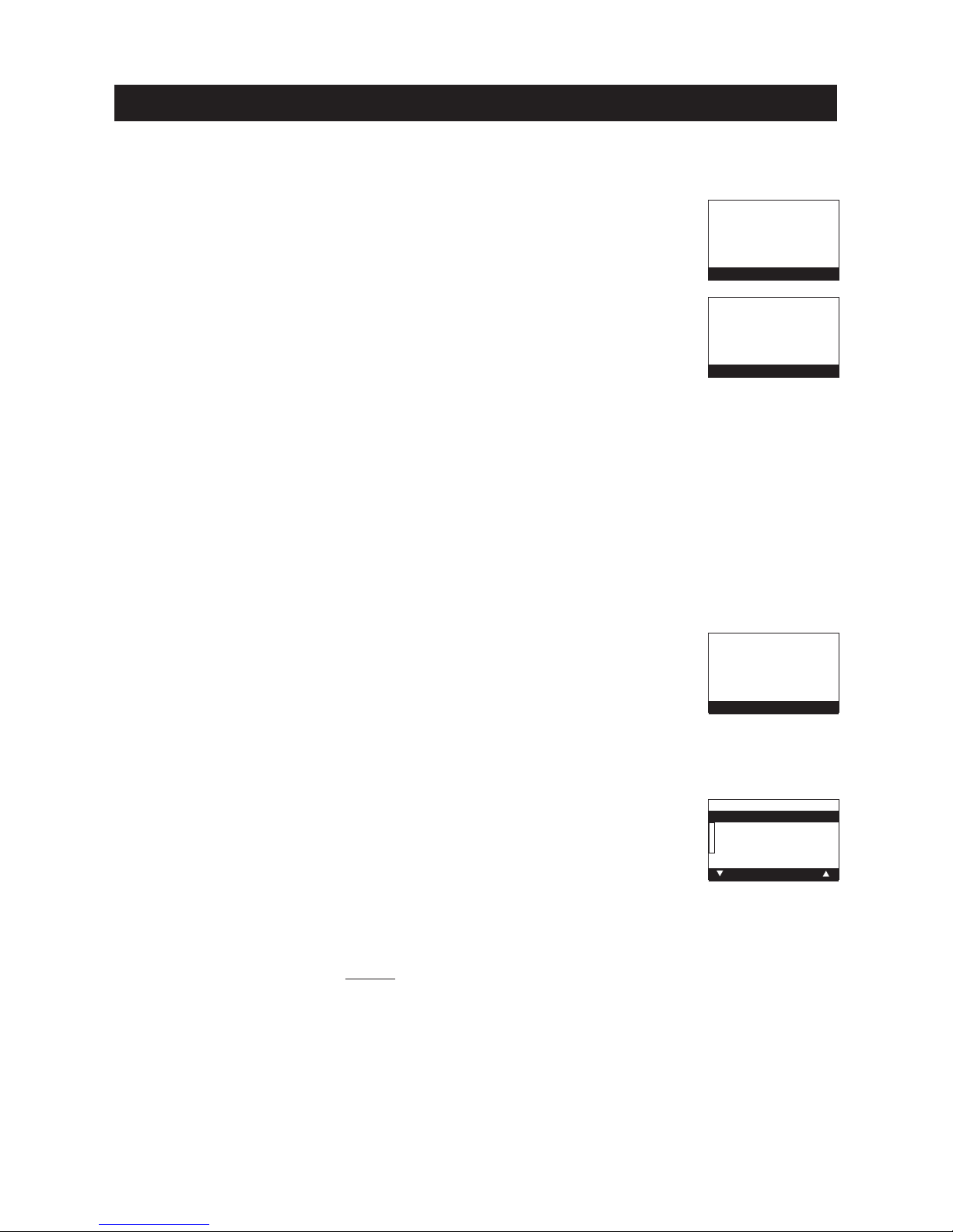
The following values are displayed:
Temp. Boiler
The current boiler temperature is displayed in °C.
Temp. chamb.
The current temperature in the combustion chamber is displayed in °C.
Fan speed
The nominal speed of the blower is displayed in rpm.
Pos. Prim. airfl.
The position of the primary air choke is displayed in %.
Pos. Sec. airfl.
The position of the secondary air choke is displayed in %.
O2 signal
The O2 signal of the lambda sensor is displayed in %.
O2 heat current
The O2 heat current of the lambda sensor is displayed in A.
Temp. Exhaust
The current flue gas temperature is displayed in °C.
Fig. 63
4.5.2 Restart temperature
The blower switches off if the boiler temperature is too high. The restart temperature is the temperature at which the blower switches back on and the boiler resumes normal heating operation.
Factory setting: 75 °C
Possible settings: 65 °C or 75 °C
Fig. 65
Temp. Boiler 68°C
Temp. chamb. 578°C
Fan speed 2150 rpm
Pos. Prim. airfl. 60%
Pos. Sec. airfl. 30%
O2 signal 18.1%
Back
Boiler temperature
for restart
Save
6655
Yes No
7755
75
°C
O2 heat current 2.5A
Temp. Exhaust 195°C
Back
4.5.3 Burnout
– automatic detection
Burnout characteristics are determined by MES thermal distribution module WVF.
If only “Solid fuel operation” is set on the WVF, “Burnout” with embers
maintenance is undertaken. With all other settings on the WVF, a normal
burnout is undertaken.
– normal
A normal burnout is always undertaken, i.e. the wood is burnt as best as
possible until no more remains without
embers maintenance.
– Embers maintenance
Burnout with embers maintenance is always undertaken, i.e. basic embers
are maintained to make it easier to light up again.
Factory setting: normal
Fig. 66
Burnout
automatic detection
normal
Embers maintenance
Save
Yes No
Fig. 64
Page 30
30
For the Service Technician
4.5.5 Actuator test
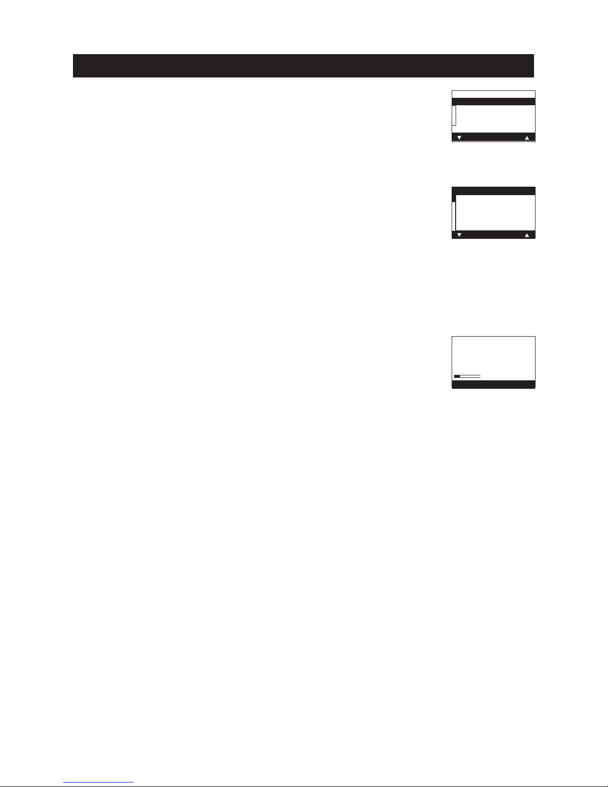
The following actuators can be selected with the
arrow
buttons, then confirmed
and started using the
Choose
button. The actuators are switched off again after
1 minute. A self-test is started at the end of an actuator test.
– Induced draught fan
– Primary airflap
– Secondary airflap
– O2 heating
4.5.6 Installation of MES modules
Display if an MES module is installed (connected) or uninstalled (disconnected) – Fig. 69.
Fig. 68
Fig. 69
Induced draught fan
Primary airflap
Secondary airflap
O2 heating
Choose Back
Installation procedure
active
.....
(Animated symbol)
4.5.4 Language
Selection of “Language” for the display texts on InfoWIN.
Fig. 67
Language
Deutsch
English
Française
Italiano
Castellano
Choose Back
Page 31
31
For the Service Technician
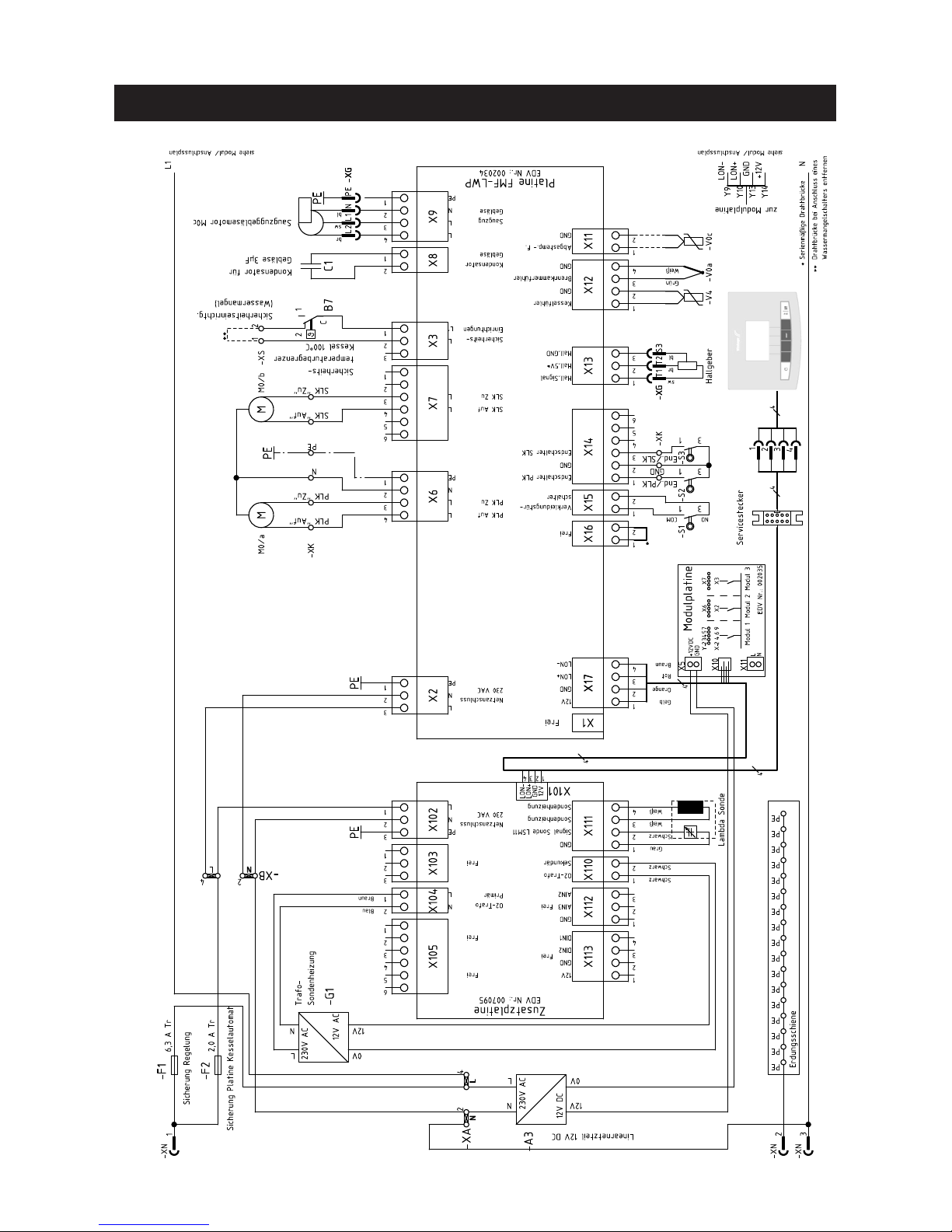
4.6 LogWIN basic circuitry
092147/02
Page 32
32
Guarantee and warranty limitations
Subject to technical modifications. AWÖ– vor-07/2008
The guarantee and warranty limitations require that the boiler and related accessories be properly installed and
started up by WINDHAGER Customer Service or Customer Service PARTNER; otherwise the manufacturer’s guarantee will not be honoured.
Malfunctions resulting from improper operation or adjustment as well as use of poor or not recommended fuel
types are not covered by the guarantee and warranty. Further, the warranty shall be void if equipment other
than those provided by WINDHAGER are installed. The special warranty restrictions for your system are available in the “Warranty Conditions” folder supplied with your boiler.
Start-up and regular maintenance following the terms of the “Warranty Conditions” will assure safe,
environmentally friendly and economical operation of your system. We recommend that you obtain a
maintenance service contract.
Contacts
Regional customer service
Salzburg: Upper Austria: Tyrol,Vorarlberg: Carinthia:
Tel. +43 (0) 62 12/23 41-267 Tel. +43 (0) 62 12/23 41-266 Tel. +43 (0) 6212/23 41-263 Tel. +43 (0) 62 12/23 41-269
Fax +43 (0) 62 12/45 04 Fax +43 (0) 62 12/45 04 Fax +43 (0) 62 12/45 04 Fax +43 (0) 62 12/45 04
Vienna, Lower Austria, Burgenland: Styria:
Tel. +43 (0) 1/869 43 28-340 or 01/86943 28-450 Tel. +43 (0) 1/869 43 28-670
Fax +43 (0) 1/865 13 81 Fax +43 (0) 1/865 13 81
E-mail: [email protected]
Technical assistance:
Tel: +43 (0) 62 12/23 41-238
Fax +43 (0) 62 12/23 41-259
Headquarters:
Windhager Zentralheizung GmbH
A-5201 Seekirchen
Anton-Windhager-Str. 20
Tel. +43 (0) 62 12/23 41-0
Fax +43 (0) 62 12/42 28
E-mail: [email protected]
Spare parts:
Tel. +43 (0) 62 12/23 41-268
Fax +43 (0) 62 12/42 26
Windhager Zentralheizung GmbH
D-86405 Meitingen
Deutzring 2
Tel. +49 (0) 82 71/8056-0
Fax +49 (0) 82 71/80 56-30
Spare parts: Tel. +49 (0) 82 71/80 56-600
E-mail: [email protected]
Customer service, western and southern Germany:
Tel. +49 (0) 82 71/8056-700
E-mail: [email protected]
Windhager Zentralheizung Schweiz AG
CH-6203 Sempach-Station
Industriestrasse 13
Tel. +41 (0) 41/46 9469-0
Fax +41 (0) 41/46 94 69-9
Spare parts: +41 (0)41/46 94 69-0
E-mail: [email protected]
Regional customer service
for German-speaking Switzerland:
Tel. +41 (0) 41/46 9469-6
E-mail: [email protected]
Windhager Zentralheizung GmbH
D-04509 Delitzsch
Heinrich-Rudolf-Hertz-Str. 2
Tel. +49 (0) 3 4202/7 23-0
Fax +49 (0) 3 42 02/7 23-30
Spare parts: Tel. +49 (0) 3 4202/7 23-600
E-mail: [email protected]
Customer service, northern and eastern Germany:
Tel. +49 (0) 3 4202/7 23-700
E-mail: [email protected]
Switzerland: Italy:
Germany:
Austria:
Windhager Zentralheizung GmbH
D-49143 Bissendorf
Gewerbepark 18
Tel. +49 (0) 54 02/70140-0
Fax +49 (0) 54 02/70 140-9
E-mail: [email protected]
Windhager Italia S.R.L.
Via Ungheresca sud
I-331010 Mareno Di Piave (TV)
Tel. +39 /0438/499143
Fax +39 /0438/497884
E-mail: [email protected]
 Loading...