

Page 1
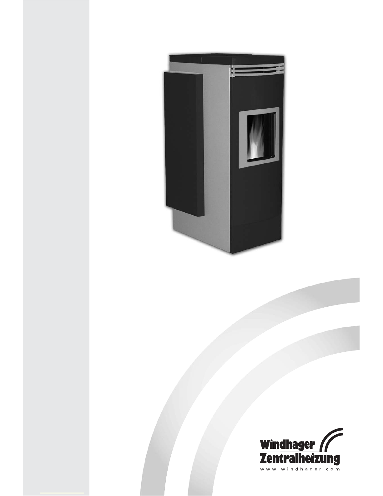
FireWIN
Pellet flue-connected boiler
Operating Manual
08/2007 092121/00
Page 2

2
Important information for system operators . . . . . . . . . . . . . . . . . . . . . . . . . . . . . . . . . . .3
1.1 Safety precautions . . . . . . . . . . . . . . . . . . . . . . . . . . . . . . . . . . . . . . . . . . . . . . . . . . . . . . . . . . . . . . . . . . . . .3
1.2 Fuel . . . . . . . . . . . . . . . . . . . . . . . . . . . . . . . . . . . . . . . . . . . . . . . . . . . . . . . . . . . . . . . . . . . . . . . . . . . . . . . . . .3
1.3 Start-up and maintenance . . . . . . . . . . . . . . . . . . . . . . . . . . . . . . . . . . . . . . . . . . . . . . . . . . . . . . . . . . . . . . .4
1.4 Heating water . . . . . . . . . . . . . . . . . . . . . . . . . . . . . . . . . . . . . . . . . . . . . . . . . . . . . . . . . . . . . . . . . . . . . . . . .4
1.5 Operating noises . . . . . . . . . . . . . . . . . . . . . . . . . . . . . . . . . . . . . . . . . . . . . . . . . . . . . . . . . . . . . . . . . . . . . . .4
1.6 Sources of danger . . . . . . . . . . . . . . . . . . . . . . . . . . . . . . . . . . . . . . . . . . . . . . . . . . . . . . . . . . . . . . . . . . . . . .5
1.6.1 Fire protection . . . . . . . . . . . . . . . . . . . . . . . . . . . . . . . . . . . . . . . . . . . . . . . . . . . . . . . . . . . . . . . . . . . . . . . . . . . . . . . . . . . . . . . . . . . .5
1.6.2 Power failure (or if the blower is not running) . . . . . . . . . . . . . . . . . . . . . . . . . . . . . . . . . . . . . . . . . . . . . . . . . . . . . . . . . . . . . . . . .5
1.6.3 Burner pot . . . . . . . . . . . . . . . . . . . . . . . . . . . . . . . . . . . . . . . . . . . . . . . . . . . . . . . . . . . . . . . . . . . . . . . . . . . . . . . . . . . . . . . . . . . . . . .5
1.6.4 Pellet storage room or storage container filling . . . . . . . . . . . . . . . . . . . . . . . . . . . . . . . . . . . . . . . . . . . . . . . . . . . . . . . . . . . . . . . .5
Operation . . . . . . . . . . . . . . . . . . . . . . . . . . . . . . . . . . . . . . . . . . . . . . . . . . . . . . . . . . . . . . . .6
2.1 Functional description, functional elements and operating controls . . . . . . . . . . . . . . . . . . . . . . . . . . . .6
2.1.1 FireWIN Klassik . . . . . . . . . . . . . . . . . . . . . . . . . . . . . . . . . . . . . . . . . . . . . . . . . . . . . . . . . . . . . . . . . . . . . . . . . . . . . . . . . . . . . . . . . . .6
2.1.2 FireWIN Premium . . . . . . . . . . . . . . . . . . . . . . . . . . . . . . . . . . . . . . . . . . . . . . . . . . . . . . . . . . . . . . . . . . . . . . . . . . . . . . . . . . . . . . . . .7
2.1.3 FireWIN Exklusiv . . . . . . . . . . . . . . . . . . . . . . . . . . . . . . . . . . . . . . . . . . . . . . . . . . . . . . . . . . . . . . . . . . . . . . . . . . . . . . . . . . . . . . . . . .8
2.1.4 Heat shield (accessory FIRE 023) . . . . . . . . . . . . . . . . . . . . . . . . . . . . . . . . . . . . . . . . . . . . . . . . . . . . . . . . . . . . . . . . . . . . . . . . . . . . .9
2.2 Check before initial start-up . . . . . . . . . . . . . . . . . . . . . . . . . . . . . . . . . . . . . . . . . . . . . . . . . . . . . . . . . . . . . .9
2.3 Filling the reserve supply container . . . . . . . . . . . . . . . . . . . . . . . . . . . . . . . . . . . . . . . . . . . . . . . . . . . . . .10
2.3.1 FireWIN Klassik – Manual filling . . . . . . . . . . . . . . . . . . . . . . . . . . . . . . . . . . . . . . . . . . . . . . . . . . . . . . . . . . . . . . . . . . . . . . . . . . . .10
2.3.2 FireWIN Premium and Exklusiv – fully automatic filling . . . . . . . . . . . . . . . . . . . . . . . . . . . . . . . . . . . . . . . . . . . . . . . . . . . . . . . . .10
2.4 InfoWIN . . . . . . . . . . . . . . . . . . . . . . . . . . . . . . . . . . . . . . . . . . . . . . . . . . . . . . . . . . . . . . . . . . . . . . . . . . . . .11
2.5 Operating modes . . . . . . . . . . . . . . . . . . . . . . . . . . . . . . . . . . . . . . . . . . . . . . . . . . . . . . . . . . . . . . . . . . . . .12
2.5.1 OFF mode . . . . . . . . . . . . . . . . . . . . . . . . . . . . . . . . . . . . . . . . . . . . . . . . . . . . . . . . . . . . . . . . . . . . . . . . . . . . . . . . . . . . . . . . . . . . . .12
2.5.2 ON mode, lighting ON, self-test, lighting OFF . . . . . . . . . . . . . . . . . . . . . . . . . . . . . . . . . . . . . . . . . . . . . . . . . . . . . . . . . . . . . . . . .12
2.5.3 Pellet feed . . . . . . . . . . . . . . . . . . . . . . . . . . . . . . . . . . . . . . . . . . . . . . . . . . . . . . . . . . . . . . . . . . . . . . . . . . . . . . . . . . . . . . . . . . . . . .13
2.5.4 Solid fuel/buffer mode . . . . . . . . . . . . . . . . . . . . . . . . . . . . . . . . . . . . . . . . . . . . . . . . . . . . . . . . . . . . . . . . . . . . . . . . . . . . . . . . . . . .13
2.5.5 Manual operation . . . . . . . . . . . . . . . . . . . . . . . . . . . . . . . . . . . . . . . . . . . . . . . . . . . . . . . . . . . . . . . . . . . . . . . . . . . . . . . . . . . . . . . .14
2.5.6 Flue cleaning function . . . . . . . . . . . . . . . . . . . . . . . . . . . . . . . . . . . . . . . . . . . . . . . . . . . . . . . . . . . . . . . . . . . . . . . . . . . . . . . . . . . .15
2.5.7 Shut-down procedure . . . . . . . . . . . . . . . . . . . . . . . . . . . . . . . . . . . . . . . . . . . . . . . . . . . . . . . . . . . . . . . . . . . . . . . . . . . . . . . . . . . . .15
2.6 Operating phases . . . . . . . . . . . . . . . . . . . . . . . . . . . . . . . . . . . . . . . . . . . . . . . . . . . . . . . . . . . . . . . . . . . . .16
2.6.1 Standby . . . . . . . . . . . . . . . . . . . . . . . . . . . . . . . . . . . . . . . . . . . . . . . . . . . . . . . . . . . . . . . . . . . . . . . . . . . . . . . . . . . . . . . . . . . . . . . .16
2.6.2 Purging . . . . . . . . . . . . . . . . . . . . . . . . . . . . . . . . . . . . . . . . . . . . . . . . . . . . . . . . . . . . . . . . . . . . . . . . . . . . . . . . . . . . . . . . . . . . . . . .16
2.6.3 Ignition phase . . . . . . . . . . . . . . . . . . . . . . . . . . . . . . . . . . . . . . . . . . . . . . . . . . . . . . . . . . . . . . . . . . . . . . . . . . . . . . . . . . . . . . . . . . .16
2.6.4 Flame stabilisation . . . . . . . . . . . . . . . . . . . . . . . . . . . . . . . . . . . . . . . . . . . . . . . . . . . . . . . . . . . . . . . . . . . . . . . . . . . . . . . . . . . . . . .16
2.6.5 Modulation mode . . . . . . . . . . . . . . . . . . . . . . . . . . . . . . . . . . . . . . . . . . . . . . . . . . . . . . . . . . . . . . . . . . . . . . . . . . . . . . . . . . . . . . . .16
2.6.6 Burnout . . . . . . . . . . . . . . . . . . . . . . . . . . . . . . . . . . . . . . . . . . . . . . . . . . . . . . . . . . . . . . . . . . . . . . . . . . . . . . . . . . . . . . . . . . . . . . . .17
2.6.7 Burner OFF . . . . . . . . . . . . . . . . . . . . . . . . . . . . . . . . . . . . . . . . . . . . . . . . . . . . . . . . . . . . . . . . . . . . . . . . . . . . . . . . . . . . . . . . . . . . .17
2.7 Information texts . . . . . . . . . . . . . . . . . . . . . . . . . . . . . . . . . . . . . . . . . . . . . . . . . . . . . . . . . . . . . . . . . . . . . .18
2.7.1 Actual boiler temperature value . . . . . . . . . . . . . . . . . . . . . . . . . . . . . . . . . . . . . . . . . . . . . . . . . . . . . . . . . . . . . . . . . . . . . . . . . . . .18
2.7.2 Boiler temperature setpoint . . . . . . . . . . . . . . . . . . . . . . . . . . . . . . . . . . . . . . . . . . . . . . . . . . . . . . . . . . . . . . . . . . . . . . . . . . . . . . . .18
2.7.3 Flue gas temperature . . . . . . . . . . . . . . . . . . . . . . . . . . . . . . . . . . . . . . . . . . . . . . . . . . . . . . . . . . . . . . . . . . . . . . . . . . . . . . . . . . . . .19
2.7.4 Current boiler output . . . . . . . . . . . . . . . . . . . . . . . . . . . . . . . . . . . . . . . . . . . . . . . . . . . . . . . . . . . . . . . . . . . . . . . . . . . . . . . . . . . . .19
2.7.5 Next boiler cleaning . . . . . . . . . . . . . . . . . . . . . . . . . . . . . . . . . . . . . . . . . . . . . . . . . . . . . . . . . . . . . . . . . . . . . . . . . . . . . . . . . . . . . .19
2.7.6 Operating hours . . . . . . . . . . . . . . . . . . . . . . . . . . . . . . . . . . . . . . . . . . . . . . . . . . . . . . . . . . . . . . . . . . . . . . . . . . . . . . . . . . . . . . . . .19
2.7.7 Total pellet consumption . . . . . . . . . . . . . . . . . . . . . . . . . . . . . . . . . . . . . . . . . . . . . . . . . . . . . . . . . . . . . . . . . . . . . . . . . . . . . . . . . .19
2.7.8 Display module software version . . . . . . . . . . . . . . . . . . . . . . . . . . . . . . . . . . . . . . . . . . . . . . . . . . . . . . . . . . . . . . . . . . . . . . . . . . .20
2.7.9 Automatic firing device software version . . . . . . . . . . . . . . . . . . . . . . . . . . . . . . . . . . . . . . . . . . . . . . . . . . . . . . . . . . . . . . . . . . . .20
2.7.10 Boiler model . . . . . . . . . . . . . . . . . . . . . . . . . . . . . . . . . . . . . . . . . . . . . . . . . . . . . . . . . . . . . . . . . . . . . . . . . . . . . . . . . . . . . . . . . . . .20
2.8 Menu guide . . . . . . . . . . . . . . . . . . . . . . . . . . . . . . . . . . . . . . . . . . . . . . . . . . . . . . . . . . . . . . . . . . . . . . . . . .21
2.8.1 Operator level . . . . . . . . . . . . . . . . . . . . . . . . . . . . . . . . . . . . . . . . . . . . . . . . . . . . . . . . . . . . . . . . . . . . . . . . . . . . . . . . . . . . . . . . . . .23
2.8.2 Service level . . . . . . . . . . . . . . . . . . . . . . . . . . . . . . . . . . . . . . . . . . . . . . . . . . . . . . . . . . . . . . . . . . . . . . . . . . . . . . . . . . . . . . . . . . . .37
2.9 Heating system operation . . . . . . . . . . . . . . . . . . . . . . . . . . . . . . . . . . . . . . . . . . . . . . . . . . . . . . . . . . . . . .38
2.9.1 FireWIN with MES system control . . . . . . . . . . . . . . . . . . . . . . . . . . . . . . . . . . . . . . . . . . . . . . . . . . . . . . . . . . . . . . . . . . . . . . . . . .38
2.9.2 FireWIN with REG standard control . . . . . . . . . . . . . . . . . . . . . . . . . . . . . . . . . . . . . . . . . . . . . . . . . . . . . . . . . . . . . . . . . . . . . . . . .39
Care, cleaning and maintenance . . . . . . . . . . . . . . . . . . . . . . . . . . . . . . . . . . . . . . . . . . . .41
3.1 Care of the front window, cladding and keyboard foil . . . . . . . . . . . . . . . . . . . . . . . . . . . . . . . . . . . . . . .41
3.2 Cleaning and operating implements . . . . . . . . . . . . . . . . . . . . . . . . . . . . . . . . . . . . . . . . . . . . . . . . . . . . . .41
3.3 Overview of intervals between maintenance . . . . . . . . . . . . . . . . . . . . . . . . . . . . . . . . . . . . . . . . . . . . . . .41
3.4 Heating surfaces . . . . . . . . . . . . . . . . . . . . . . . . . . . . . . . . . . . . . . . . . . . . . . . . . . . . . . . . . . . . . . . . . . . . .43
3.5 Ash pan, ash on heating surface . . . . . . . . . . . . . . . . . . . . . . . . . . . . . . . . . . . . . . . . . . . . . . . . . . . . . . . . .43
3.6 Combustion chamber (baffle plate, temperature sensor) . . . . . . . . . . . . . . . . . . . . . . . . . . . . . . . . . . . . .44
3.7 FireWIN reserve supply container . . . . . . . . . . . . . . . . . . . . . . . . . . . . . . . . . . . . . . . . . . . . . . . . . . . . . . . .46
3.8 Top heating surfaces and linkage . . . . . . . . . . . . . . . . . . . . . . . . . . . . . . . . . . . . . . . . . . . . . . . . . . . . . . . .48
3.9 Pressure measuring nipple, rotary feeder, blower wheel, blower box and exhaust pipe . . . . . . . . . . .49
3.9.1 Pressure measuring nipple for combustion chamber pressure switch . . . . . . . . . . . . . . . . . . . . . . . . . . . . . . . . . . . . . . . . . . . . .49
3.9.2 Rotary feeder . . . . . . . . . . . . . . . . . . . . . . . . . . . . . . . . . . . . . . . . . . . . . . . . . . . . . . . . . . . . . . . . . . . . . . . . . . . . . . . . . . . . . . . . . . . .49
3.9.3 Blower wheel, blower box and exhaust pipe to flue . . . . . . . . . . . . . . . . . . . . . . . . . . . . . . . . . . . . . . . . . . . . . . . . . . . . . . . . . . . .50
Troubleshooting . . . . . . . . . . . . . . . . . . . . . . . . . . . . . . . . . . . . . . . . . . . . . . . . . . . . . . . . . .51
4.1 No display on InfoWIN . . . . . . . . . . . . . . . . . . . . . . . . . . . . . . . . . . . . . . . . . . . . . . . . . . . . . . . . . . . . . . . . .52
4.2 Information messages . . . . . . . . . . . . . . . . . . . . . . . . . . . . . . . . . . . . . . . . . . . . . . . . . . . . . . . . . . . . . . . . .52
4.3 Fault messages . . . . . . . . . . . . . . . . . . . . . . . . . . . . . . . . . . . . . . . . . . . . . . . . . . . . . . . . . . . . . . . . . . . . . . .52
4.4 Alarm messages . . . . . . . . . . . . . . . . . . . . . . . . . . . . . . . . . . . . . . . . . . . . . . . . . . . . . . . . . . . . . . . . . . . . . .53
Guarantee and warranty limitations . . . . . . . . . . . . . . . . . . . . . . . . . . . . . . . . . . . . . . . . .56
Contacts . . . . . . . . . . . . . . . . . . . . . . . . . . . . . . . . . . . . . . . . . . . . . . . . . . . . . . . . . . . . . . . .56
Table of contents:
Page 3

3
Important information for system operators
Dear Heating System Owners,
We would like to congratulate you on your new environmentally friendly boiler system. With the purchase of
this high-quality product by WINDHAGER ZENTRALHEIZUNG, you have selected a system that provides more
comfort and optimised fuel consumption while utilising an environmentally friendly means of saving resources.
Your boiler was manufactured under strict ISO 9001 certified standards, was subjected to extensive tests and
is recyclable with all components.
On the following pages we have provided specific information and important tips regarding system operation,
unit functions and cleaning. Please pay close attention to these instructions. Familiarity with the material in this
document will allow you to enjoy long-term operation of the unit. We wish you all the best with your WINDHAGER boiler!
Cordially,
WINDHAGER ZENTRALHEIZUNG
Caution symbols
Please take careful note of the following symbols in this Operating Manual.
Ignoring the identified warnings can lead to personal injury.
Ignoring the identified warnings can lead to malfunction of, or damage to the boiler or heating sys-
tem.
1.1 Safety precautions
The boiler and related accessories reflect the state of the art and meet all applicable safety regulations.
Your boiler and all accessories operate using 230 VAC electrical current. Improper installation or repair can pose
the danger of life-threatening electrical shock. Installation may be performed only by appropriately qualified
technicians.
The pellets must be stored in a dry place so that they can be transported without problems and in order to
achieve trouble-free operation with optimum combustion and at maximum efficiency.
1.2 Fuel
The boilers are designed to burn the following fuels:
Pellets according to ÖNORM M7135 or DINplus.
Significant criteria based on the standards are as follows:
Diameter 6 mm Length 80% between 15 – 30 mm
Smooth surface Density at least 1.1 kg/dm3
Residual moisture content max. 10%
Energy content min. 18 MJ/kg = 5 kWh/kg
(in water-free condition)
Ash content max. 0.5% Abraded particles max. 2.3%
Chemical/synthetic binding agents are strictly prohibited No impurities from varnish or paint residues, etc.
Page 4

4
Important information for system operators
1.3 Start-up and maintenance
Please permit Windhager Customer Service or have one of our customer service PARTNERS put your new boiler into service. In this way, all functions of the new unit will be thoroughly checked; you will also benefit from
the detailed information provided by the system installer. Installation by a qualified technician as well as the
maintenance required by the guarantee limitations will guarantee the optimal use and service life of your boiler system. This is the only means to assure the benefits of this technologically advanced boiler and guarantee
safe, environmentally friendly and energy-saving system operation.
The following preconditions must be met before you order the initial start-up:
1.) Boiler installed correctly.
2.) System fully wired up electrically.
3.) System rinsed, filled and vented – heat consumption must be possible.
4.) Boiler connected to domestic water and filled.
5.) Sufficient quantity of fuel available (pellets, split logs, oil or gas).
6.) The customer must be present during start-up.
The initial start-up cannot be carried out if any of these points is neglected. The customer will be charged for
any unnecessary costs arising as a result.
Start-up and maintenance are part of the guarantee requirements of the enclosed “guarantee limitations”.
Note:
During the first few weeks after start-up, condensation can occur in the combustion chamber, ash pan
and on the heating surfaces. This has no effect on the function and service life of the boiler.
1.4 Heating water
The chemical composition of the heating water must meet the specifications of ÖNORM H 5195 Part 1 or VDI
2035 P1. According to ÖNORM M 5195 Part 1, the condition of the heating water must be checked every 2 years
by a heating technician in order to avoid corrosion and sediment accumulation in the heating system.
The check must be performed once every year in heating systems with more than 1500 litres of heating water.
In the event of repair work requiring a change of water in the heating system, the heating water is to be checked
within 4 to 6 weeks after such work.
Corrosion and sediment resulting from improper heating water are not covered by the guarantee and warranty.
1.5 Operating noises
The FireWIN is a modern, fully automated pellet flue-connected boiler with a high level of convenience in terms
of operation and cleaning. This automation means that operating noises may occur during normal operation.
Normal operating noises are:
Flame noises – Natural flame noise can be heard depending on the size of the flames.
Light scratching and scraping noises – Depending on the level of contamination, cleaning noises may occur
during automated cleaning or ash removal. If these become louder over time ⇒ clean the pellet flue-connected boiler and, in particular, the burner pot.
Trickling of pellets and vacuum cleaner noise – Fully automated pellet supply involves pellets being sucked from
the storage room into the reserve supply container. During filling, the suction turbine generates a “vacuum cleaner noise” in the storage room and the feed hose, and the trickling of the pellets can be heard in the reserve
supply container.
Clicking noises – The relays switch on or off when the control unit is installed.
Page 5
5
Never fill the burner pot with pellets by hand. Excessive combustion material in the burner pot means
that the pellets will not be ignited optimally. Too much low temperature carburisation gas will be generated and this can lead to deflagration.
During filling, negative pressure is created in the pellet
store and this can cause burn-back in the pellet flue-connected boiler. Therefore, the boiler must be stopped from
operating during the filling procedure or 15 minutes in
advance.
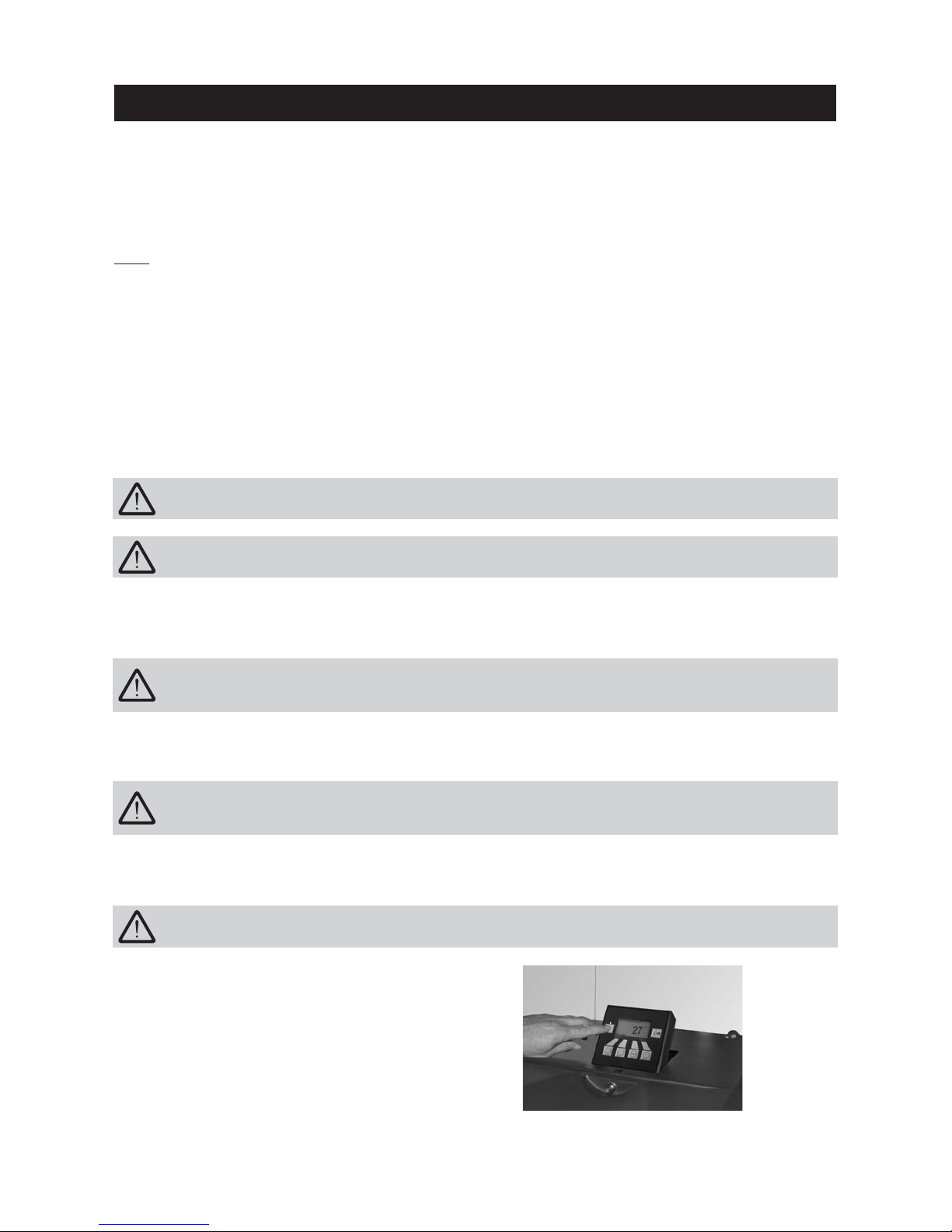
The pellet flue-connected boiler must be switched off at the ON/OFF button on the InfoWIN at least 15
minutes before the store is filled – Fig. 2.
1.6.4 Pellet storage room or storage container filling
1.6.3 Burner pot
Do not open the combustion chamber door, there is an increased risk of deflagration when opening the
combustion chamber door. A self-test is performed following a power failure during combustion and
then operation is continued automatically.
1.6 Sources of danger
1.6.1 Fire protection
The entire system must comply with technical fire protection requirements in accordance with the applicable
regulations, standards and guidelines.
All flammable materials in the close vicinity of the pellet flue-connected boiler must be protected against the
effects of heat, in particular in the area of the front window.
Fig. 2 Switching off FireWIN
Do not drape clothing or other items over the FireWIN for drying them.
1.6.2 Power failure (or if the blower is not running)
Important information for system operators
Do not touch the front window – danger of burns.
Liquid noise, gurgling – This is caused by air in the heating water ⇒ bleed the system.
Air induction noises – Air induction noise occurs at the air supply induction point for combustion (air opening
in the device) ⇒ Use air supply pipes to relocate the induction point outside the house or into an adjacent room.
Light whistling noises – Above the front window on the door frame, there are openings for the window air-
wash function that can give rise to whistling noises if they are dirty ⇒ clean the holes.
Note:
Due to these operating and flame noises, we do not recommend installing the device in bedrooms or
quiet rooms – see also the information in the FireWIN installation instructions, “Installation”.
Page 6
6
Operation
2.1 Functional description, function elements and operating
controls
The FireWIN pellet flue-connected boiler and the Modular Energy System MES or the REG standard control
combine to form a perfect unit. The FireWIN automatically fires when the control system signals a heating
requirement. Following “purging” (safety function), ignition starts and the pellet metering auger switches on.
The burner pot is automatically filled with pellets. When flame formation has been detected (temperature sensor), the boiler enters flame stabilisation mode and then control mode (modulation mode) and keeps to the
specified boiler temperature setpoint (between 60 °C and 75 °C). The boiler enters burnout mode if the heat
consumed drops below the minimum nominal thermal output or no heating requirement is signalled by the
control system. The blower continues to run until the burner pot has cooled down. Therefore, do not switch off
the electricity supply to the device too soon.
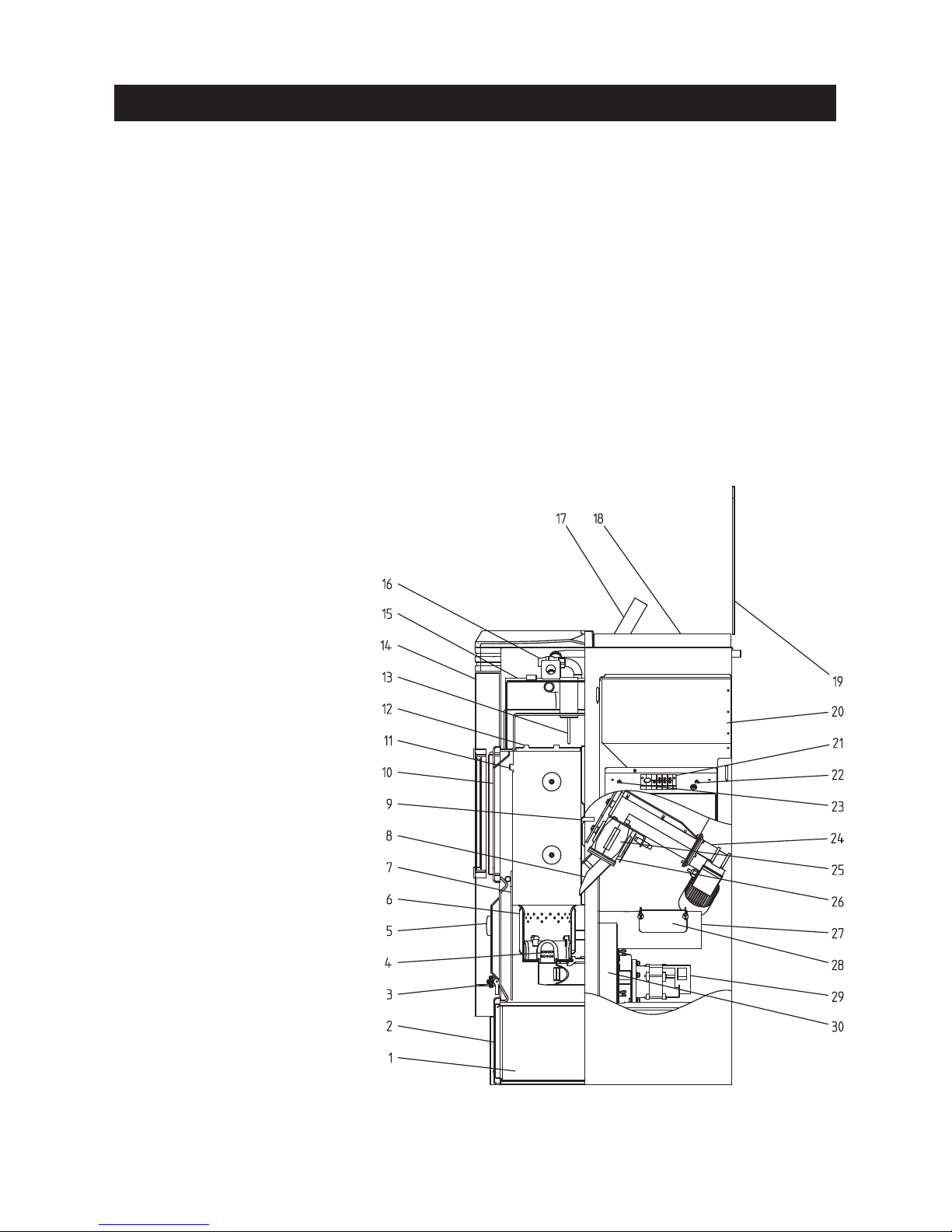
2.1.1 FireWIN Klassik
The reserve supply container is loaded by hand. The heating surfaces are cleaned manually using the cleaning
lever. The cleaning residues from the heating surfaces and the combustion residues from the burner pot drop
into the ash pan or ash pan space.
Fig. 3 FireWIN Klassik – view from right
1 . . . .Ash pan
2 . . . .Ash door
3 . . . .Filling and evacuation cock
4 . . . .Primary air pin
5 . . . .Pressure gauge
6 . . . .Burner pot
7 . . . .Heat shield
8 . . . .Down chute
9 . . . .Pressure measuring nipple
10 . . .Combustion chamber door
11 . . .Lug for hanging in
the heat shield
12 . . .Baffle plate
13 . . .Temperature sensor
14 . . .Cladding door
15 . . .Heating surface cover
16 . . .Safety valve
17 . . .InfoWIN operating unit
18 . . .Reserve supply container cover
19 . . .Glass cover
20 . . .Pellet reserve supply container
21 . . .1 MES module or with
2 or more modules in the wall-mount
casing
22 . . .Boiler temperature
safety thermostat B7
23 . . .Rotary feeder
safety thermostat B7a
24 . . .Auger and motor
25 . . .Rotary feeder
26 . . .Rotary feeder cleaning opening
27 . . .Exhaust pipe
28 . . .Exhaust pipe cleaning opening
29 . . .Blower motor
30 . . .Blower box
Page 7
7
Operation
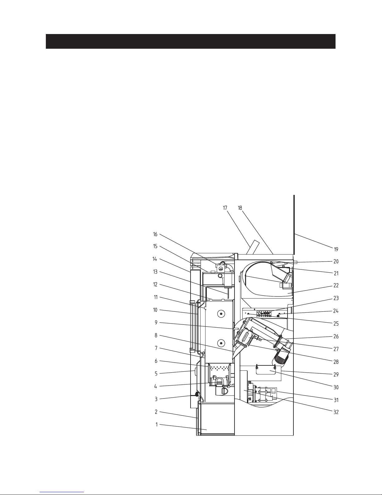
2.1.2 FireWIN Premium
Version as FireWIN Klassik, but in addition with fully automated pellet feed
The pellet feed uses a maintenance-free suction turbine to fill the FireWIN reserve supply container fully automatically with pellets from a pellet storage room or storage container. The pellet feed is switched on by the
lower fill level switch (proximity switch) in the reserve supply container or at the end of the enable time or the
beginning of the start time, and runs for as long as the reserve supply container is full. Filling is not started if
the boiler is in heating operation or the feed has been blocked by the control unit (not during the enable time
e.g. at night). If the boiler is operating when filling is necessary, the boiler switches to burnout mode.
Switching between suction wands 1, 2 and 3 is fully automatic. The system changes to the next suction wand
after the reserve supply container has been filled a certain number of times. This means the storage room is
evenly emptied to a large extent.
Fig. 4 FireWIN Premium – view from right
1 . . . .Ash pan
2 . . . .Ash door
3 . . . .Filling and evacuation cock
4 . . . .Primary air pin
5 . . . .Pressure gauge
6 . . . .Burner pot
7 . . . .Heat shield
8 . . . .Down chute
9 . . . .Pressure measuring nipple
10 . . .Combustion chamber door
11 . . .Lug for hanging in
the heat shield
12 . . .Baffle plate
13 . . .Temperature sensor
14 . . .Cladding door
15 . . .Heating surface cover
16 . . .Safety valve
17 . . .InfoWIN operating unit
18 . . .Reserve supply container cover
19 . . .Glass cover
20 . . .Inspection cover
21 . . .Coarse filter
22 . . .Pellet reserve supply container
23 . . .1 MES module or with
2 or more modules in the wall-mount
casing
24 . . .Boiler temperature
safety thermostat B7
25 . . .Rotary feeder
safety thermostat B7a
26 . . .Auger and motor
27 . . .Rotary feeder
28 . . .Rotary feeder cleaning opening
29 . . .Exhaust pipe
30 . . .Exhaust pipe cleaning opening
31 . . .Blower motor
32 . . .Blower box
Page 8
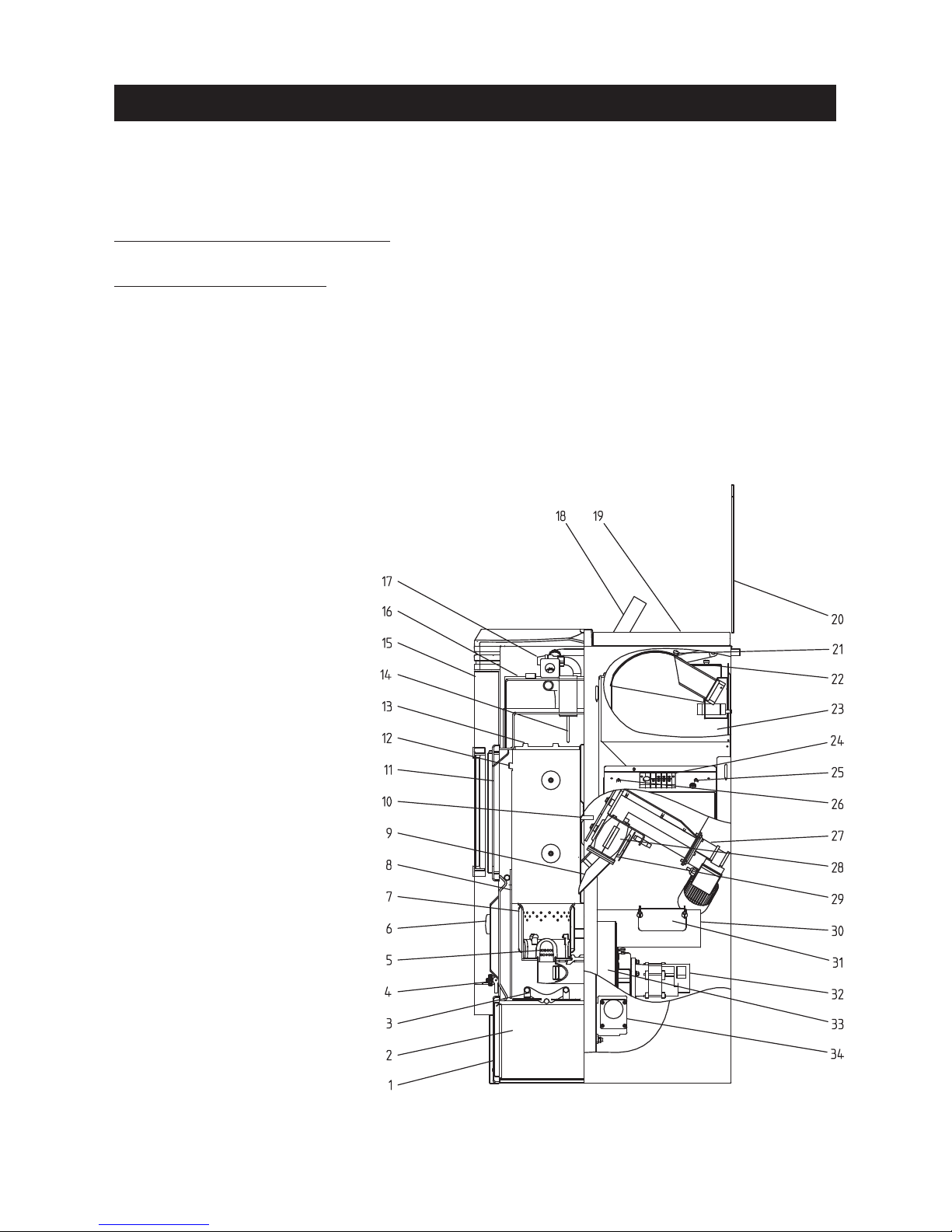
8
Operation
2.1.3 FireWIN Exklusiv
Version as FireWIN Premium, but in addition with fully automated heating surface cleaning and ash
compactor
Fully automated heating surface cleaning:
A motor moves the heating surface cleaning system vertically and the heating surfaces remain clean.
Fully automated ash compactor:
The fully automated ash compactor uses a motor and pressure plate to compress the ash in the ash container
fully automatically. This makes the emptying intervals up to 3 times longer.
Fig. 5 FireWIN Exklusiv – view from right
1 . . . .Ash pan
2 . . . .Ash door
3 . . . .Ash compactor
4 . . . .Filling and evacuation cock
5 . . . .Primary air pin
6 . . . .Pressure gauge
7 . . . .Burner pot
8 . . . .Heat shield
9 . . . .Down chute
10 . . .Pressure measuring nipple
11 . . .Combustion chamber door
12 . . .Lug for hanging in
the heat shield
13 . . .Baffle plate
14 . . .Temperature sensor
15 . . .Cladding door
16 . . .Heating surface cover
17 . . .Safety valve
18 . . .InfoWIN operating unit
19 . . .Reserve supply container cover
20 . . .Glass cover
21 . . .Inspection cover
22 . . .Coarse filter
23 . . .Pellet reserve supply container
24 . . .1 MES module or with
2 or more modules in the wall-
mount casing
25 . . .Boiler temperature
safety thermostat B7
26 . . .Rotary feeder
safety thermostat B7a
27 . . .Auger and motor
28 . . .Rotary feeder
29 . . .Rotary feeder
cleaning opening
30 . . .Exhaust pipe
31 . . .Exhaust pipe cleaning opening
32 . . .Blower motor
33 . . .Blower box
34 . . .Motor for ash compaction
Page 9
9
Operation
2.2 Check before initial start-up
a) System pressure (heating water pressure):
The system must be filled and vented. With the system cold, pressure should be at least 1.0 bar (maximum
1.8 bar) – Fig. 8. If you have any questions, your installer will gladly answer them.
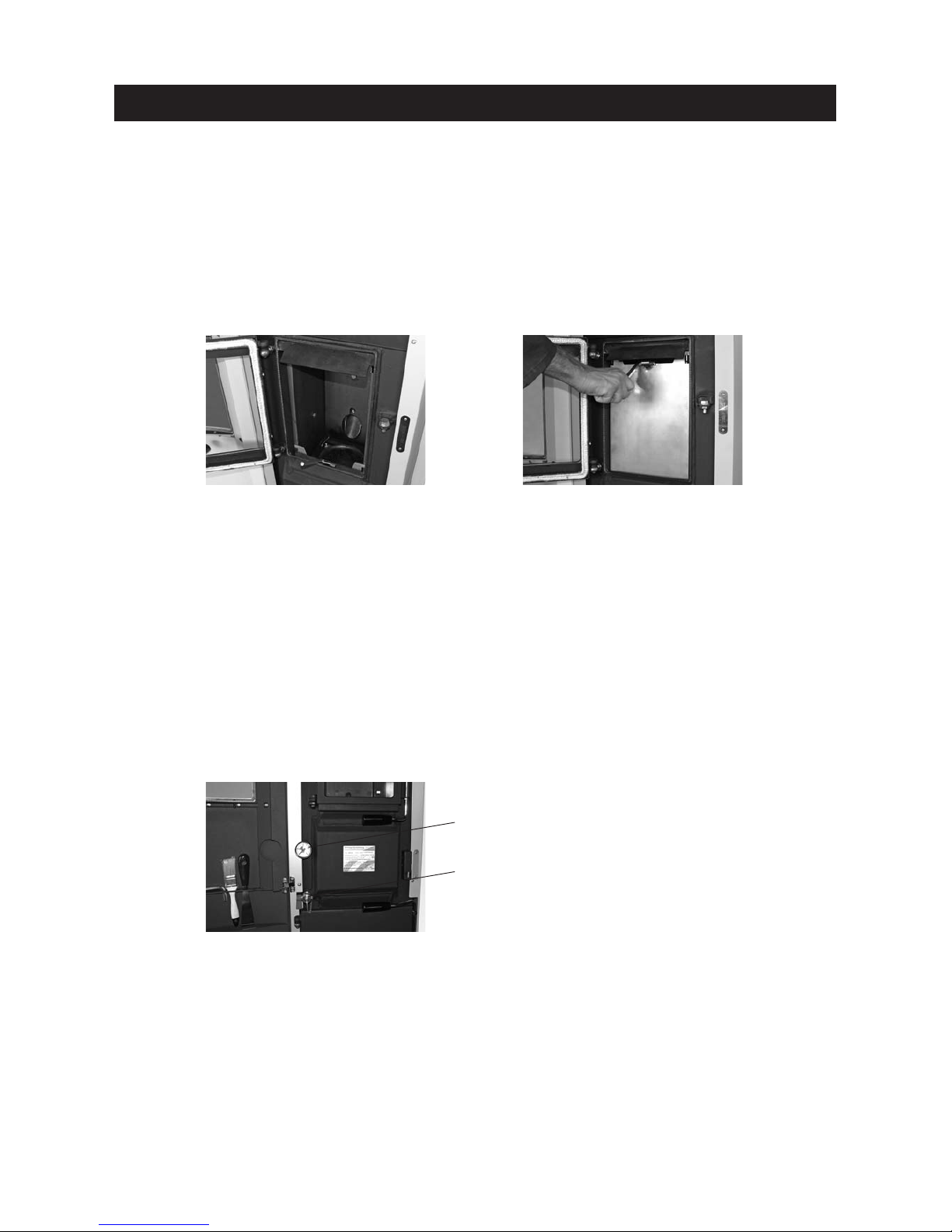
2.1.4 Heat shield (accessory FIRE 023)
Heat radiated from the front window can lead to unwanted heating of the room where the unit has been set up
when domestic hot water is heated during the summer. If you do not wish for the room to be heated, you can
significantly reduce the amount of heat radiated using the patented heat shield (accessory Fire 023).
The distribution of heat between air and water heating is approx. 15 : 85 % without the heat shield and approx. 9 : 91 %
with the heat shield pushed up.
The heat shield is located in the combustion chamber. This can be pulled up using the supplied Allen key and
hooked into the lugs on the sides of the combustion chamber cover plates, Figs. 6, 7.
Fig. 6 Hooking in the Allen key Fig. 7 Pulling up the heat shield and hook-
ing it into the lugs on the sides
Pressure gauge (system pressure)
Fig. 8 Filling the system
b) Ventilation:
If you are operating the device with room air, please make sure the room where it is installed is well ventilated. The air supply must be as free of dust as possible.
c) Flue:
Please have the chimney sweep check the flue, and, if necessary, clean it.
Filling and evacuation cock
Page 10
10
2.3 Filling the reserve supply container
2.3.1 FireWIN Klassik – Manual filling
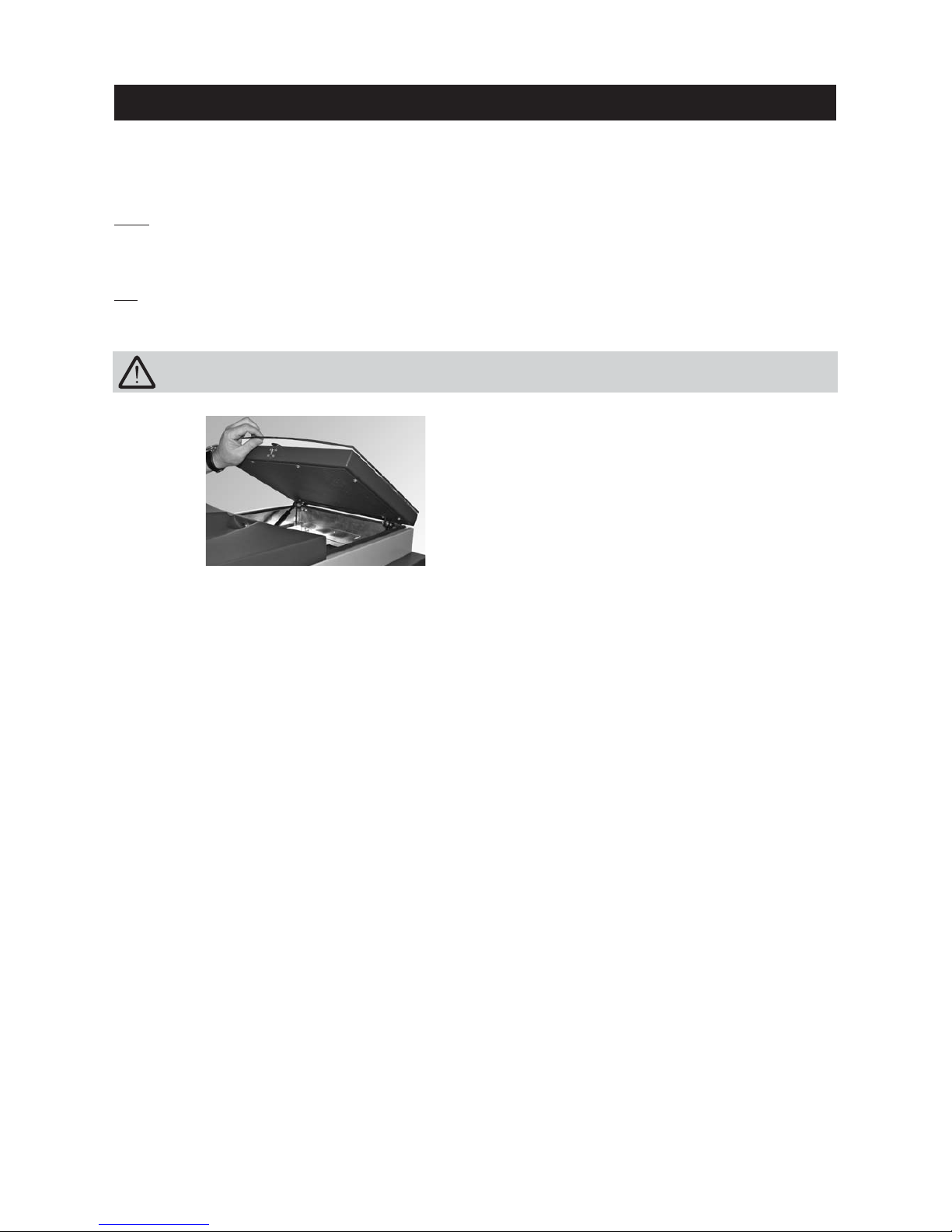
Note: Do not open the reserve supply container cover unless the glass cover is closed, in order to avoid damaging the glass cover.
Fold open the cover of the reserve supply container (Fig. 9) and fill the reserve supply container up to max. 1
cm below the edge. Close the cover.
T
ip: The reserve supply container should always be completely filled with pellets. This allows the incoming pellets to drop into the container better, reduces the size of the conical part of the pile and means that the container empties better.
Fig. 9 Folding open the cover
When filling, make sure no extraneous materials (e.g. shreds of the pellet bags resulting from cutting
open the bags) get into the reserve supply container – they could block the rotary feeder!
2.3.2 FireWIN Premium and Exklusiv – fully automatic filling
The reserve supply container is filled by the fully automated pellet feed. WINDHAGER Customer Service or the
customer service PARTNER will perform the first fill (start-up), take the boiler and its pellet supply into service
and familiarize the customer with the operation and cleaning of the boiler, with reference to the Operating Manual.
Operation
Page 11
11
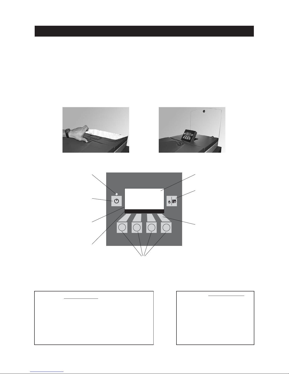
2.4 InfoWIN
The InfoWIN is located at the top under the glass cover. Press the locking button at the front and fold the glass
cover open, the InfoWIN pops up automatically – Figs. 10, 11. It consists of a large full text display, an ON/OFF
button with an LED signal lamp indicating Operation (green) or Malfunction (red), a button for manual operation / flue cleaning function as well as four individual menu buttons. The function of each menu button is displayed on the Menu line.
Note: If the text on the display moves out of position, the display will be corrected during the next automatic
refresh (after about 30 minutes). Such a shift or distortion might be caused by an electrostatic discharge or the
like.
5s
RESET
Full-text display
(illuminated display)
Manual operation / flue cleaning
function
Signal lamp (LED)
“Operation” – green;
“Malfunction” – red
Menu buttons
ON/OFF button
Menu line
Operating phases are displayed here, including
Standby, Burner OFF, etc.
Assignment of buttons to
their specific function
Operation
The various operating modes are displayed on InfoWIN together with the corresponding operating phases.
The following operating modes exist:
– OFF
– ON (with self-test, lighting ON, lighting OFF)
– Pellet feed
– Solid fuel / buffer mode
– Manual operation
– Flue cleaning function
– Shut-down procedure
Corresponding operating phases:
– Standby
– Purging
– Ignition phase
– Flame stabilisation
– Modulation mode
– Burnout
– Burner OFF
– Switch off heat generator
Boiler temperature
Standby
Info Menu
38
°C
Fig. 12 InfoWIN
Fig. 10 Press the locking button Fig. 11 InfoWIN pops up
Page 12
12
5s
RESET5sRESET5sRESET
Operation
2.5 Operating modes
2.5.1 OFF mode
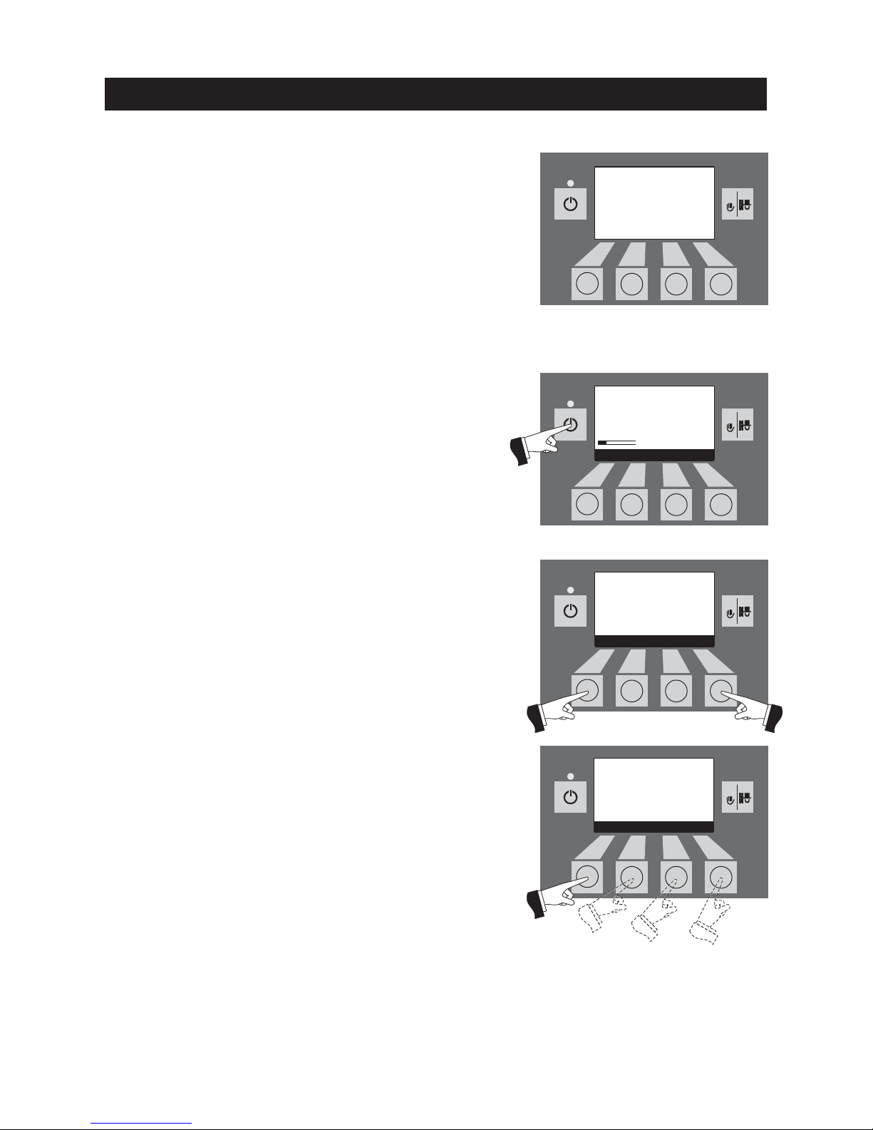
When operation is shut off, the display is inactive and all buttons,
with the exception of the ON/OFF button are not functional. The
LED on the InfoWIN does not light – Fig. 13.
2.5.2 ON mode, lighting ON,
self-test, lighting OFF
Press the ON/OFF button, the self-test starts automatically – Fig. 14.
Fig. 15 Standard display
Fig. 16 Display lighting OFF
After a successful self-test, the display shows an operating phase
and the boiler water temperature (standard display). The LED signal lamp lights green and the desired functions can be selected
using the buttons – Fig. 15.
If the self-test was unsuccessful, an information message (e.g. information, fault, alarm) is displayed (see page 51).
The display lighting switches off automatically after 45 seconds
(Fig. 16). Pressing one of the six buttons switches the lighting on
again for 45 seconds.
InfoWIN identifies and stores the various operating modes and
states. Once the system is switched on, other operating modes may
also be displayed instead of the standard display, such as manual
operation, solid fuel or buffer tank operation; malfunctions are also
displayed. These operating modes and states are described later
in these instructions.
Fig. 14 Self-test
5s
RESET
Fig. 13 OFF mode
Self-test
active
.....
(Animated symbol)
Boiler temperature
(Operating phases)
Info Menu
42
°C
Boiler temperature
(Operating phases)
Lighting ON
42
°C
Page 13

13
Operation
2.5.4 Solid fuel / buffer mode
If the FireWIN pellet flue-connected boiler is combined with a solid fuel boiler or an accumulator tank, the WVF or BUL module automatically switches
over between pellet and solid fuel/buffer mode.
Combustion of the FireWIN is stopped when the WVF or BUL module sends
the request to switch over to solid fuel/buffer mode – Fig. 19.
Following this, the system switches over to solid fuel/buffer mode and the
FireWIN burner is locked – Fig. 20
If the pellet flue-connected boiler is switched off using the ON/OFF button on
the InfoWIN, an automatic switchover to solid fuel/buffer mode is performed
in conjunction with a WVF module. Once the InfoWIN unit is switched on, the
pellet flue-connected boiler can be locked out for a maximum of 15 minutes
due to switch-over delays. This is displayed by InfoWIN – Fig. 20.
Fig. 19
Fig. 20
Solid fuel/
buffer mode
Burnout
Info Menu
42
°C
Solid fuel/
buffer mode
Burner locked
Info Menu
42
°C
2.5.3 Pellet feed
Pellet feed – burnout
Pellet feed from the storage room into the reserve supply container has been
requested. Combustion is stopped. Pellet transport into the burner pot is
stopped, the vacuum fan continues to run until all the remaining pellets have
been burned and the burner pot has cooled down. – Fig. 17.
Pellet feed in operation
The pellet feed is in operation. Pellets are supplied from the storage room into
the reserve supply container. The burner is locked – Fig. 18.
Fig. 17
Fig. 18
Pellet feed
Burnout
Info Menu
42
°C
Pellet feed
in operation
Burner locked
Info Menu
42
°C
Page 14
14
5s
RESET5sRESET
5s
RESET5sRESET
Operation
2.5.5 Manual operation
Fig. 21
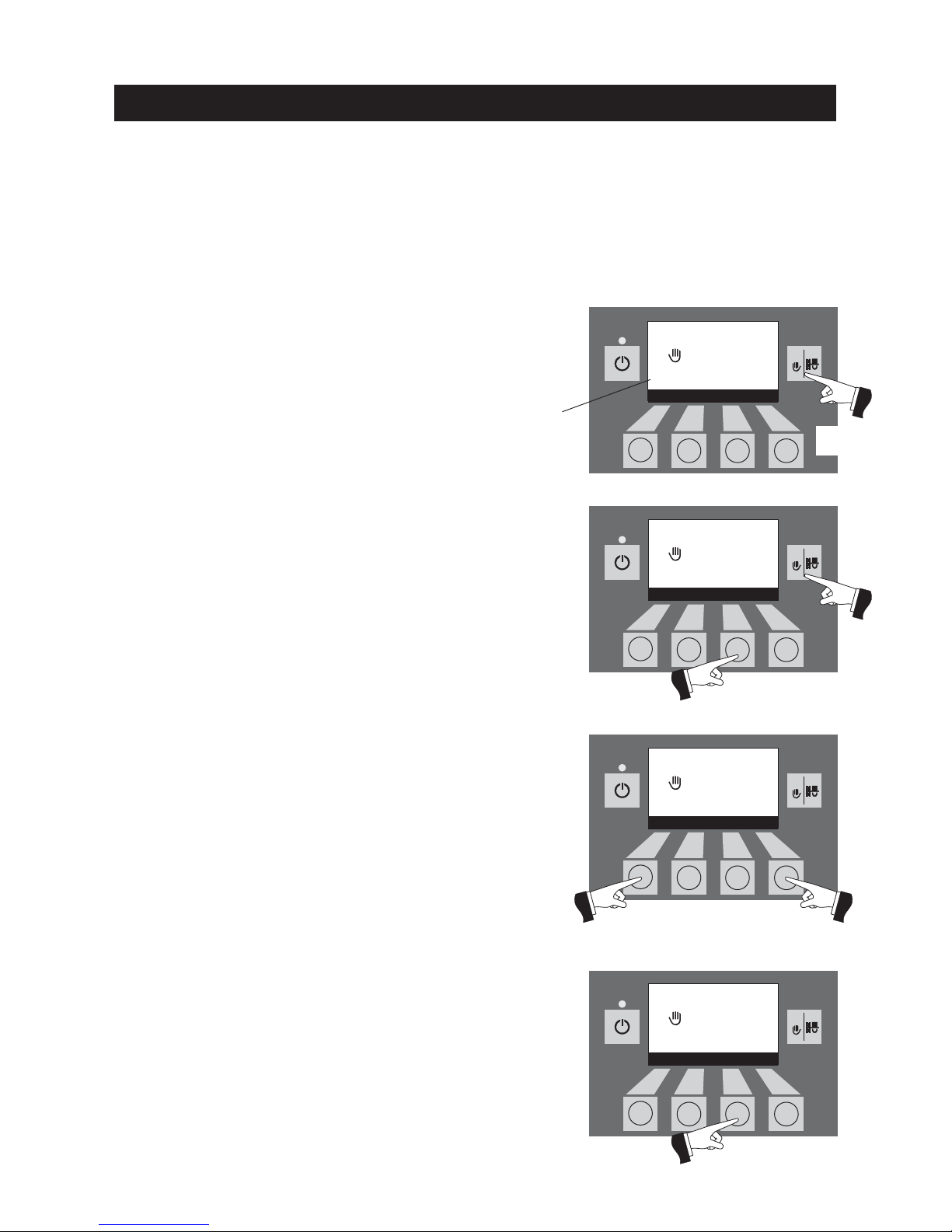
Pressing the Cancel button or Manual operation / flue cleaning function button terminates the function – Fig. 22. The boiler returns to
automatic operation.
SSeettppooiinntt aaddjjuussttmmeenntt ffoorr mmaannuuaall ooppeerraattiioonn
Pressing the + or – button causes the display to switch to the setpoint adjustment mode – Fig. 23. Using the + or – button can
change the setpoint in 1 K steps. The temperature set in this mode
is not permanently saved. The original set temperature is used once
manual operation ends.
After pushing the Return button (Fig. 24) or after waiting about 10
seconds, the screen returns to its previous display.
Press for
5 seconds
The various operating phases are displayed here, including Burner in operation, Burner OFF, etc.
Fig. 22
Fig. 23
Fig. 24
Manual operation starts if the Manual operation / flue cleaning function button is pressed for longer than five seconds – Fig. 21. The boil-
er temperature is controlled in relation to the setpoint for manual
operation (standard temperature: 60 °C). The current automatic setting is not affected by this. The lighting is switched off after the lighting timer has counted down (45 seconds); the function or display
remains unchanged.
Note: Manual operation cannot be started in “solid fuel/buffer mode”. Manual operation is not allowed to be
started if an installed solid fuel boiler is operating (heated up). Manual operation is allowed to be started if there
is no solid fuel boiler installed or is not operating but only the accumulator tank is active. In this case, first set
the operating mode switch on the WVF module to relay test 2 or on the BUL module to relay test 1 (see WVF
or BUL module operating manual).
14
Manual operation
Boiler temperature
(Operating phases)
––
Cancel
++
42
°C
(Symbol flashes)
Manual operation
Boiler temperature
(Operating phases)
––
Cancel
++
42
°C
(Symbol flashes)
Manual operation
Set temperature
––
Back
++
70
°C
(Symbol flashes)
Manual operation
Set temperature
––
Back
++
70
°C
(Symbol flashes)
Page 15
15
5s
RESET5sRESET
5s
RESET5sRESET
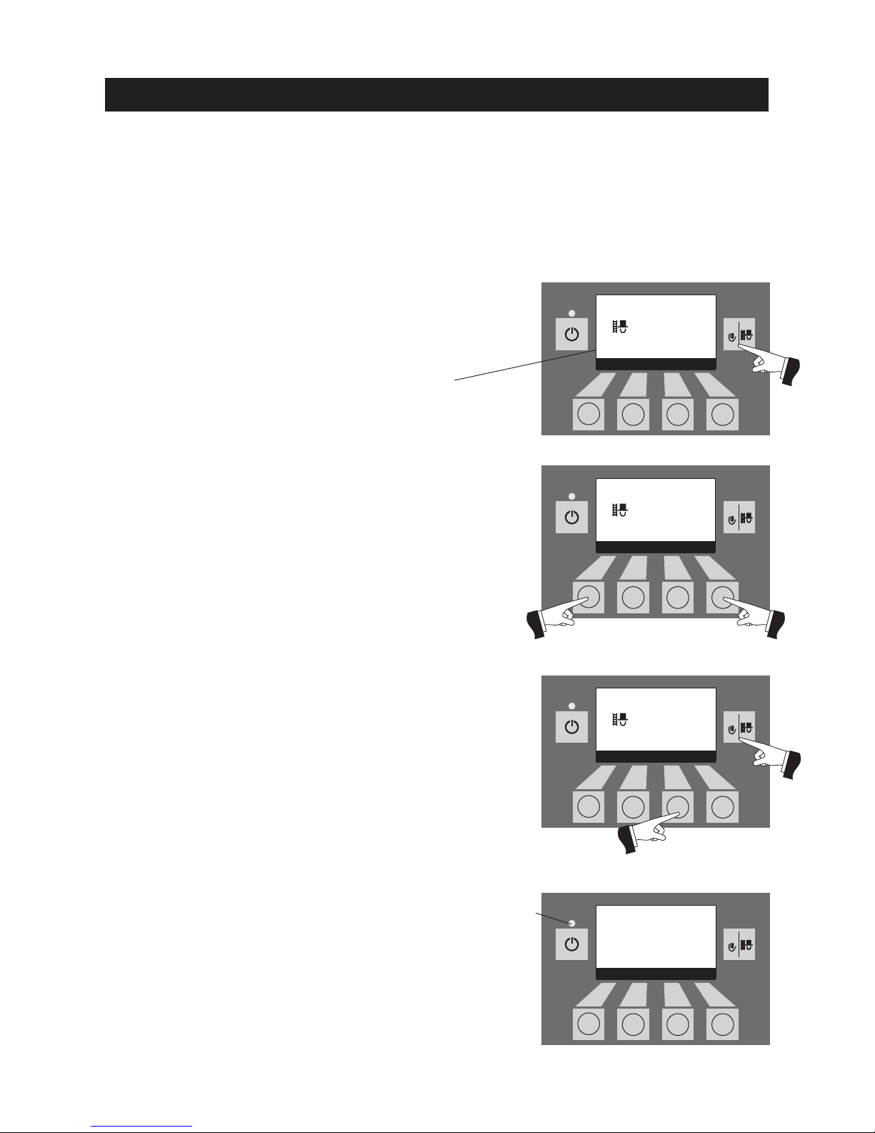
A short press of the Manual operation / flue cleaning function button
switches on the display lighting. Pressing the button again starts the
flue cleaning function – Fig. 25. The boiler temperature is regulated
to approx. 60 °C.
Operation
2.5.6 Flue cleaning function
This function aids the performance of legally-required emissions testing.
The flue cleaning function ends
– if the Cancel button or Manual operation / flue cleaning function but-
ton is pressed – Fig. 27.
– automatically after about 45 minutes.
The various operating phases are displayed here, including Burner in operation, Burner OFF, etc.
Fig. 27
Fig. 26
Fig. 25
2.5.7 Shut-down procedure
The boiler is switched off – Fig. 28.
Fig. 28
The green LED flashes
Note: The flue cleaning function cannot be started in “solid fuel/buffer mode”. The flue cleaning function is not
allowed to be started if an installed solid fuel boiler is operating (heated up). The flue cleaning function is allowed
to be started if there is no solid fuel boiler installed or is not operating but only the accumulator tank is active.
In this case, first set the operating mode switch on the WVF module to relay test 2 or on the BUL module to
relay test 1 (see WVF or BUL module operating manual).
Pressing the corresponding menu button enables the boiler to be
operated with 30 % or 100 % output – Fig. 26. The lighting is switched
off after the lighting timer has counted down (45 seconds); the function or display remains unchanged. The first button press only switches on the lighting.
Flue cleaning function
Power 100%
(Operating phases)
30% Cancel 100%
42
°C
(Symbol flashes)
Flue cleaning function
Power 30%
(Operating phases)
30% Cancel 100%
42
°C
(Symbol flashes)
Flue cleaning function
Power 30%
(Operating phases)
30% Cancel 100%
42
°C
(Symbol flashes)
Shut-down procedure
Burnout
Info Menu
42
°C
Page 16

16
2.6 Operating phases
2.6.1 Standby
During this operating phase, the controls do not transmit requests for heat.
The burner is switched off and the boiler temperature setpoint is 0 °C – Fig. 29.
2.6.2 Purging
The vacuum fan runs, the combustion chamber of the FireWIN is flushed
through with fresh air. This phase can last several minutes before the burner
fires – Fig. 30.
2.6.5 Modulation mode
The burner is in modulation mode. The output is infinitely varied between 30
% and 100 % – Fig. 33.
Operation
2.6.3 Ignition phase
The vacuum fan runs, pellets are transported into the burner pot and are ignited. When flame formation is detected, the system switches over to flame stabilisation – Fig. 31.
2.6.4 Flame stabilisation
Following the ignition procedure, even combustion is established and then the
system switches over to modulation mode – Fig. 32.
Fig. 29
Fig. 30
Fig. 31
Fig. 32
Fig. 33
Boiler temperature
Standby
Info Menu
42
°C
Boiler temperature
Purging
Info Menu
42
°C
Boiler temperature
Ignition phase
Info Menu
42
°C
Boiler temperature
Flame stabilisation
Info Menu
42
°C
Boiler temperature
Modulation mode
Info Menu
42
°C
Page 17

17
Operation
2.6.6 Burnout
Combustion is stopped. Pellet transport into the burner pot is stopped, the vacuum fan continues to run until all the remaining pellets have been burned and
the burner pot has cooled down – Fig. 34.
2.6.7 Burner OFF
There is a heating requirement from the control system, but the boiler temperature (actual value) is higher than the boiler temperature setpoint. This
means combustion is stopped and the burner is switched off – Fig. 35.
Fig. 34
Fig. 35
Boiler temperature
Burnout
Info Menu
42
°C
Boiler temperature
Burner OFF
Info Menu
42
°C
Page 18
18
5s
RESET
5s
RESET5sRESET
2.7.1 Current boiler temperature
The current boiler temperature of the FireWIN is displayed – Fig. 39.
2.7.2 Boiler temperature setpoint
The display indicates the boiler temperature as calculated by the control system. This setpoint is used to control the burner – Fig. 40.
Operation
Fig. 36
2.7 Information text
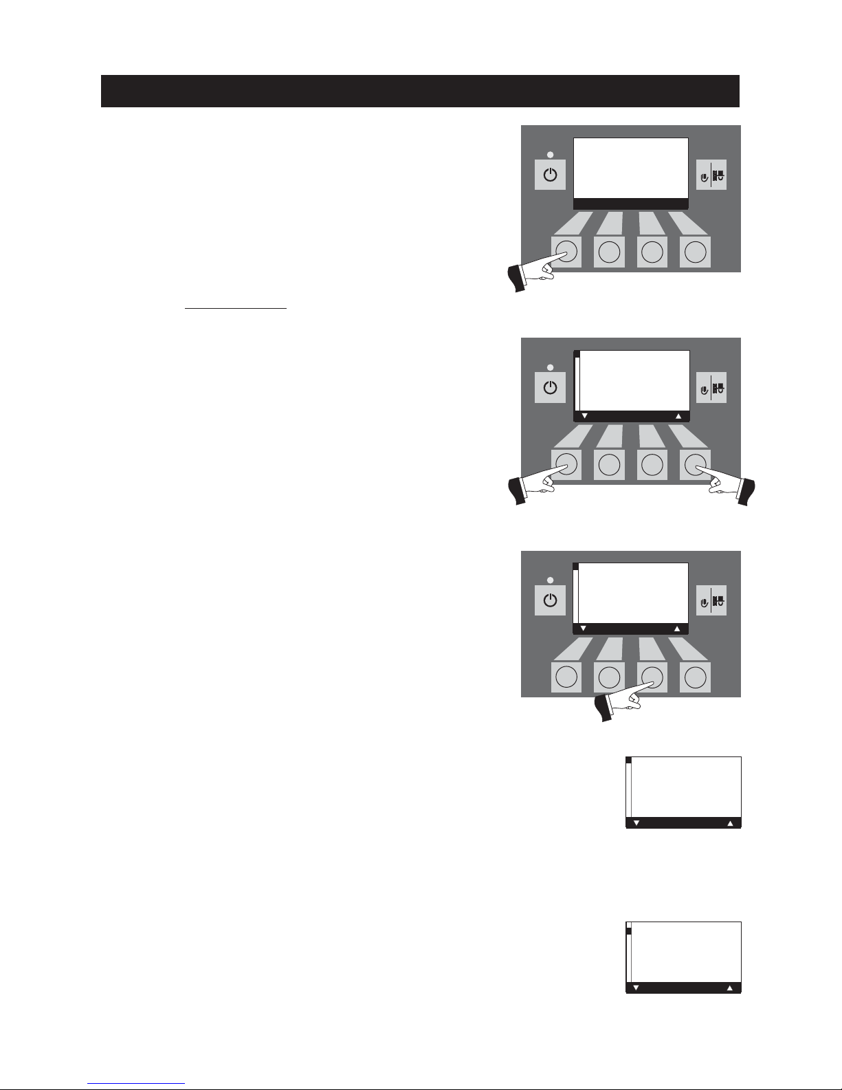
Pressing the Info button calls up the most important FireWIN information – Fig. 36.
The arrow buttons select and display sub-menus – Fig. 37. Pushing the Back button (Fig. 38) or waiting 45 seconds returns to the
standard display.
The following information texts exist:
– Actual boiler temperature (°C)
– Boiler temperature setpoint (°C)
– Flue gas temperature (°C)
– Current boiler output (%)
– Next boiler cleaning in (h)
– Operating hours (h)
– Total pellet consumption (t)
– Display module software version
– Automatic firing device software version
– Boiler model
Fig. 37
Fig. 38
Fig. 39
Fig. 40
Boiler temperature
(Operating phases)
Info Menu
42
°C
Boiler temperature
actual value
Back
42
°C
Boiler temperature
actual value
Back
42
°C
Boiler temperature
actual value
Back
42
°C
Boiler temperature
setpoint
Back
63
°C
Page 19
19
Operation
2.7.4 Current boiler output
The current boiler output is displayed in %. The boiler output (modulation
mode) can be set from 30 % to 100 % – Fig. 42.
Fig. 42
2.7.6 Operating hours
The total number of burner operating hours is displayed – Fig. 44.
Fig. 44
Current
boiler output
Back
70
%
Operating hours
Back
1,234
h
2.7.5 Next boiler cleaning
Display of the operating time in hours remaining until the next boiler cleaning – Fig. 43.
Note: The operating time remaining until the next boiler cleaning depends
on the operating method and is constantly recalculated. Therefore, there may
be deviations from the normal operating hours.
Fig. 43
Next boiler
cleaning in approx.
Back
300
h
2.7.3 Flue gas temperature
If a flue gas temperature sensor (accessory) is connected, this function displays the current flue gas temperature – Fig. 41.
Fig. 41
Flue gas temperature
Back
114
°C
2.7.7 Total pellet consumption
The total amount of pellets consumed is displayed in tonnes. The pellet consumption is used in determining cleaning intervals and maintenance work (see
page 41, Care, cleaning, maintenance) – Fig. 45.
Note:The “Total pellet consumption” is a calculated value and can differ from
the actual value by ±15%.
Fig. 45
Total pellet consumption
Back
1.30
t
Page 20
20
Operation
2.7.8 Display module software version
The current software version of the display module (InfoWIN) is displayed –
Fig. 46.
2.7.9 Automatic firing device software version
The current software version of the automatic firing device is displayed –
Fig. 47.
2.7.10 Boiler model
The boiler model of the FireWIN is displayed – Fig. 48.
Fig. 46
Fig. 47
Fig. 48
Software version
Display module
Back
2.50
Software version
Automatic firing device
Back
2.50
Boiler model
Pellet boiler 120K
Back
Page 21
21
5s
RESET5sRESET5sRESET5sRESET
Operation
2.8 Menu guide
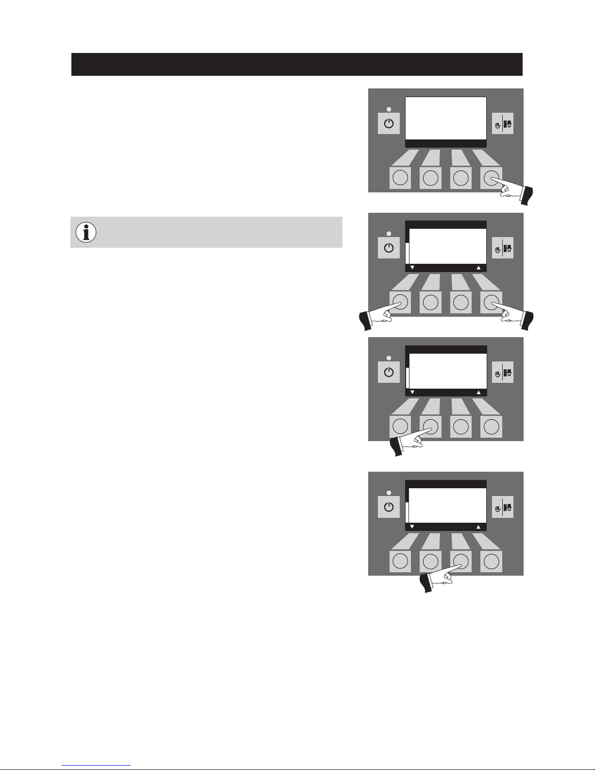
Pressing the Menu button changes the menu display to the Operator level or the Service level – Fig. 49.
Use the arrow buttons to select the Operator level (Fig. 50) and confirm with the Choose button – Fig. 51.
The menu item or sub-menu item is exited by pressing the Back
button (Fig. 52) or after a delay of 45 seconds.
Fig. 49
Fig. 50
Fig. 51
Fig. 52
Only trained service personnel may perform system modifications on the Service level.
Boiler temperature
(Operating phases)
Info Menu
42
°C
Operator level
Service level
Choose Back
Operator level
Service level
Choose Back
Operator level
Service level
Choose Back
Page 22
22
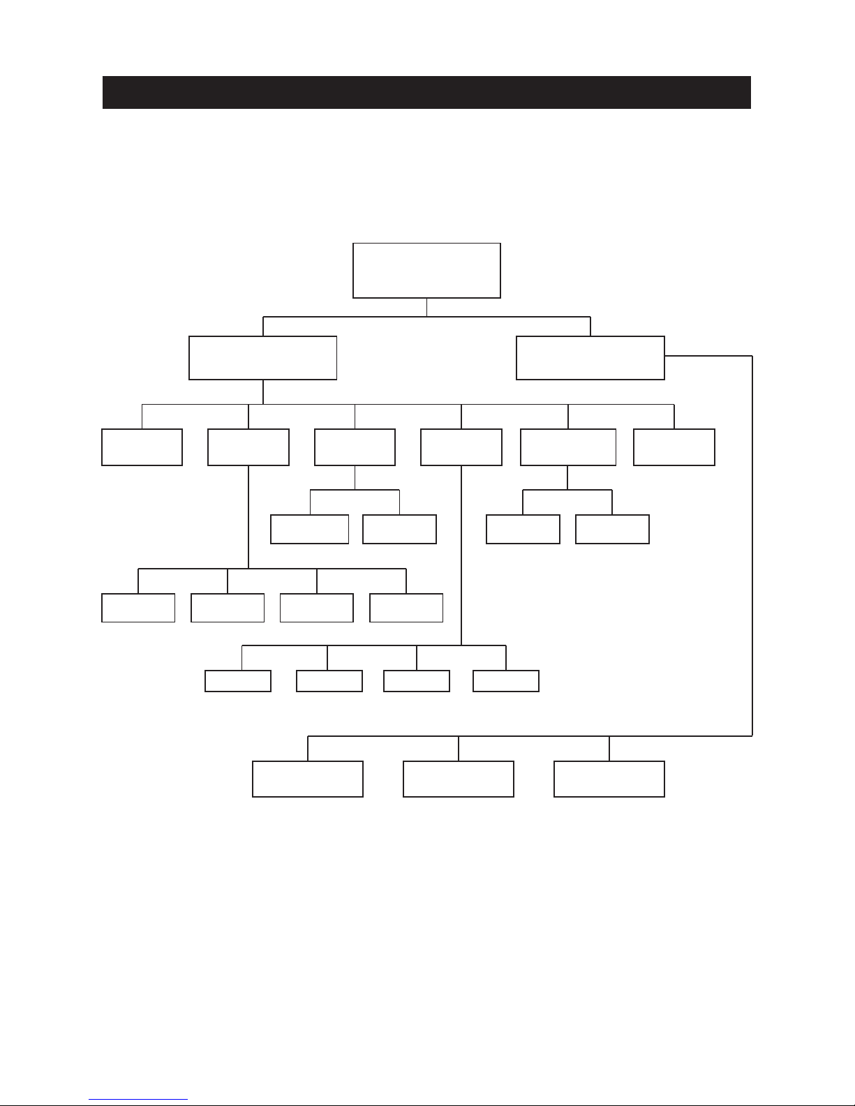
Menu structure:
Operator level
Service level
(reserved for trained service
personnel only)
Time
Feed operat-
ing mode
Time profile
feed
Wand
switching
Menu
with enable
time
with start time
without
time control
switched off
automated Wand 1 only Wand 2 only Wand 3 only
with enable time:
Start/finish
with start time:
Start
Start-up
Only trained service personnel may perform parameter settings, start-up, the actuator test and
make changes (see FireWIN installation instructions);
Operation
Parameters Actuator test
Ash compr.
time profile
Boiler
cleaning
Start time 1
08:00
Start time 2
22:00
Page 23
23
5s
RESET
5s
RESET5sRESET5sRESET
Fig. 53
Fig. 54
The menu item or sub-menu item is exited by pressing the Back
button (Fig. 55) or after a delay of 45 seconds.
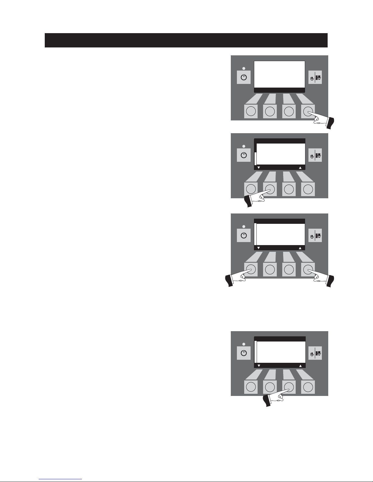
2.8.1 Operator level
Pressing the Menu button changes to the “Operator level” and
“Service level” – Fig. 53.
Fig. 55
Operation
The Arrow buttons select the “Operator level”; the Choose button
confirms the choice – Fig. 54.
On the Operator level, use the Arrow buttons to select the required
sub-menu (Fig. 55); the Choose button confirms the choice.
Adjusting the:
time: See section 2.8.1.1.
Feed operating mode see section 2.8.1.2.
Time profile feed see section 2.8.1.3.
Wand switching see section 2.8.1.4.
Fig. 55
Note: The menu items “Feed operating mode”, “Time profile feed”
and “Wand switching” are only shown if a feed or wand switching
function is provided and activated on the service level.
Time
Feed operating mode
Time profile feed
Wand switching
Ash compr. time profile
Boiler cleaning
Choose Back
Boiler temperature
(Operating phases)
Info Menu
42
°C
Operator level
Service level
Choose Back
Time
Feed operating mode
Time profile feed
Wand switching
Ash compr. time profile
Boiler cleaning
Choose Back
Page 24
24
5s
RESET5sRESET5sRESET5sRESET5sRESET
Operation
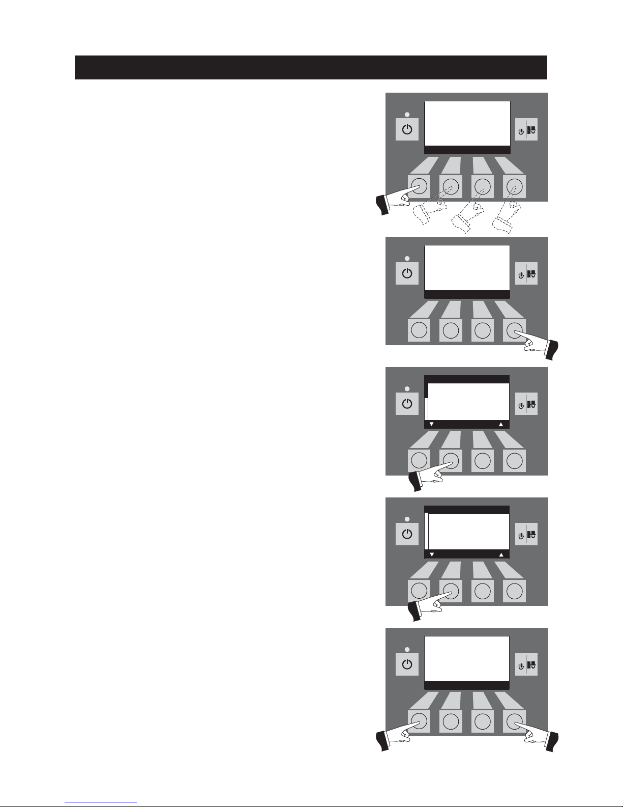
2.8.1.1 Setting the time
This time is used for the time control of the pellet feed.
If the FireWIN is operated with an MES control, the time is auto-
matically adopted from the module and the time set here is overwritten.
Pressing one of the four menu buttons switches the lighting on –
Fig. 56.
Fig. 56
Fig. 57
Fig. 58
Fig. 59
Fig. 60
Press the Menu button – Fig. 57.
Confirm the selected menu item “Operator level” by pressing the
Choose button – Fig. 58.
Confirm the selected “Time” sub-menu by pressing the Choose but-
ton – Fig. 59.
The arrow buttons set the required time – Fig. 60.
Set the time
Save
––
Yes No
++
13:50
Boiler temperature
(Operating phases)
Lighting ON
42
°C
Time
Feed operating mode
Time profile feed
Wand switching
Ash compr. time profile
Boiler cleaning
Choose Back
Boiler temperature
(Operating phases)
Info Menu
42
°C
Operator level
Service level
Choose Back
Page 25
25
5s
RESET5sRESET5sRESET
Fig. 61
Operation
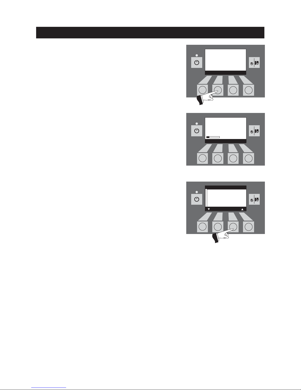
Confirm the changed time by pressing the Ye s button – Fig. 61.
The display shows “Saving parameter value” for a few seconds
(Fig. 62) and then changes back to the previous level – Fig. 63.The
menu item or sub-menu item is exited by pressing the Back but-
ton (Fig. 63) or after a delay of 45 seconds.
Fig. 62
Fig. 63
Saving parameter value
.....
(Animated symbol)
Set the time
Save
––
Yes No
++
13:50
Time
Feed operating mode
Time profile feed
Wand switching
Ash compr. time profile
Boiler cleaning
Choose Back
Page 26
26
5s
RESET5sRESET
5s
RESET
5s
RESET5sRESET
Operation
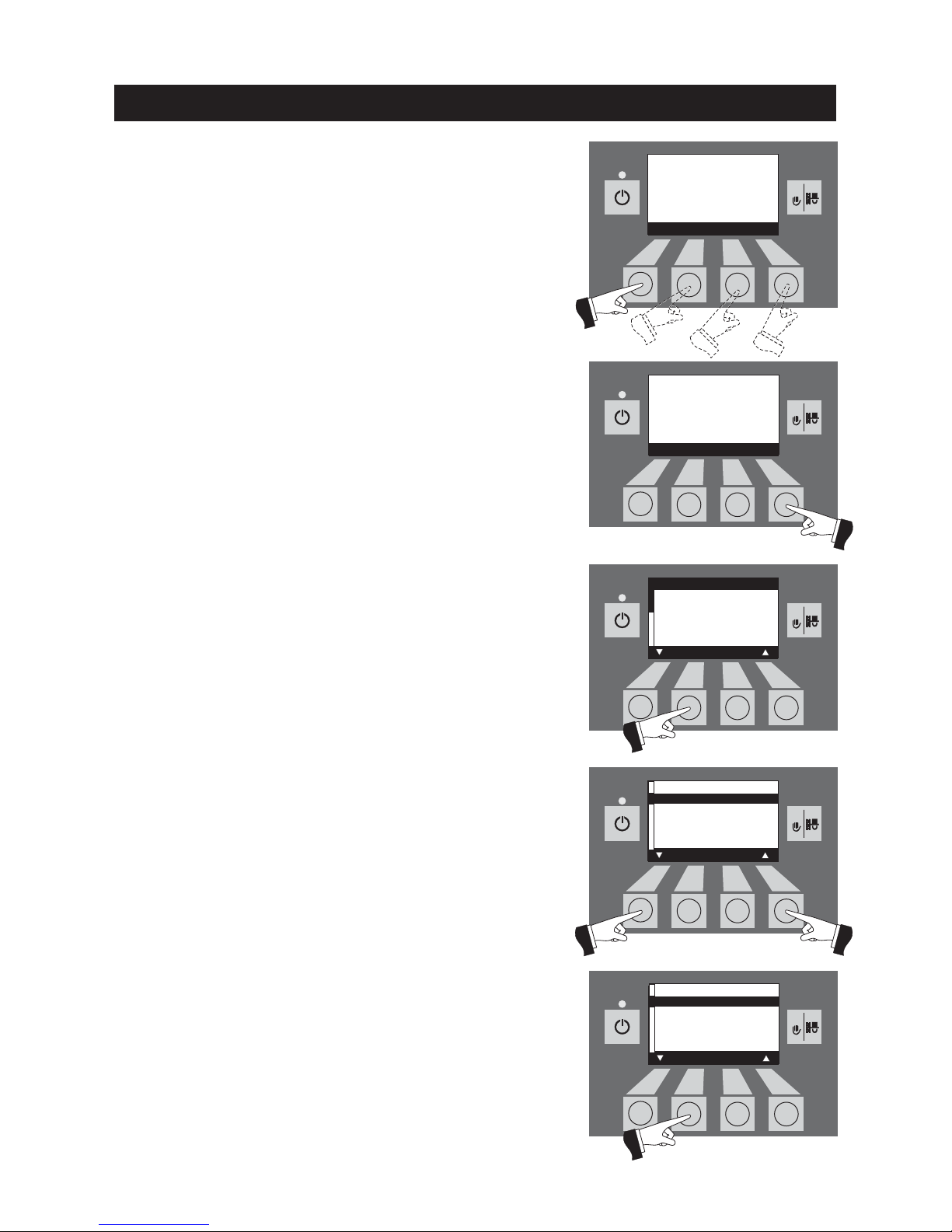
2.8.1.2 Setting the feed operating mode
This menu item sets:
– whether the feed is switched off, or
– whether the feed should fill the pellet boiler with or without time
control.
Pressing one of the four menu buttons switches the lighting on –
Fig. 64.
Fig. 64
Fig. 65
Fig. 66
Fig. 67
Press the Menu button – Fig. 65.
Confirm the selected menu item “Operator level” by pressing the
Choose button – Fig. 66.
The arrow buttons select the “Feed operating mode” sub-menu –
Fig. 67.
Confirm the selected sub-menu “Feed operating mode” by pressing the Choose button – Fig. 68.
Fig. 68
Time
Feed operating mode
Time profile feed
Wand switching
Ash compr. time profile
Boiler cleaning
Choose Back
Boiler temperature
(Operating phases)
Lighting ON
42
°C
Boiler temperature
(Operating phases)
Info Menu
42
°C
Operator level
Service level
Choose Back
Time
Feed operating mode
Time profile feed
Wand switching
Ash compr. time profile
Boiler cleaning
Choose Back
Page 27
27
Burning duration with 25 kg pellets
FireWIN Burning duration at nominal output
FW 090 approx. 12.5 h
FW 120 approx. 10 h
5s
RESET
5s
RESET5sRESET5sRESET
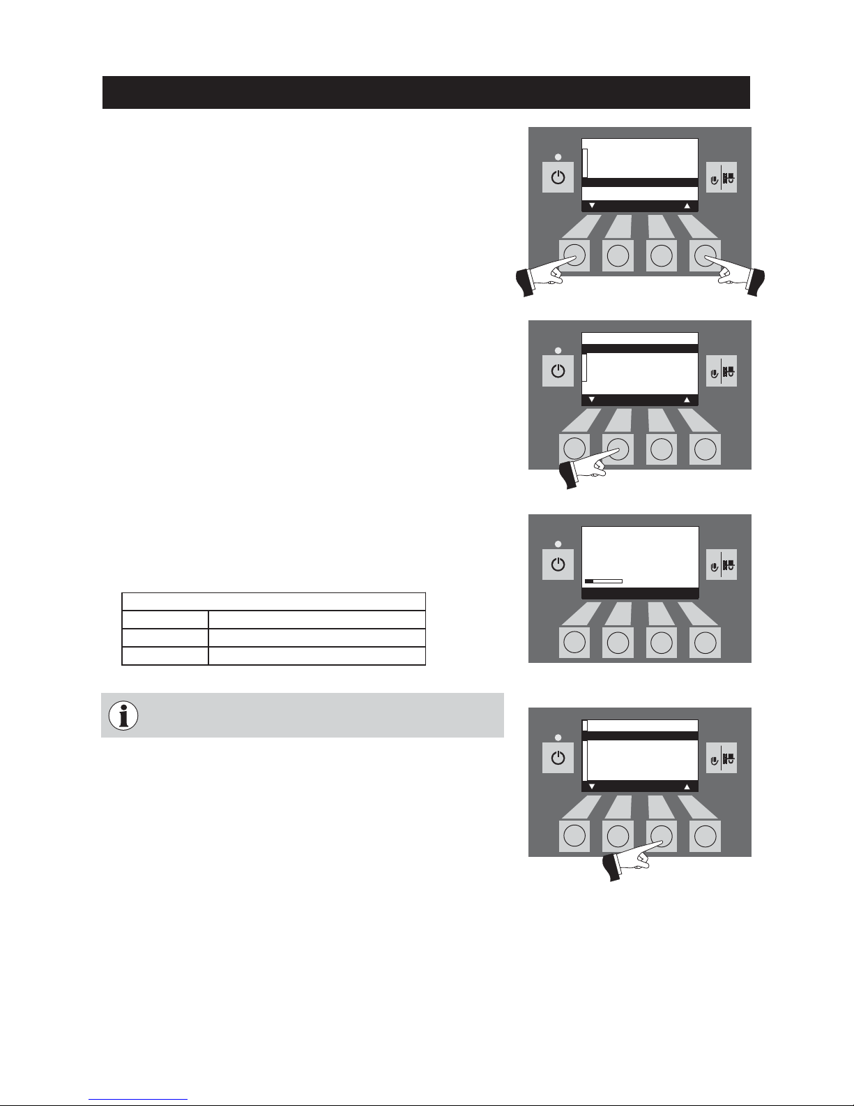
The factory setting for the “Feed operating modem” menu item is
“switched off”.
without time control: Select this if the feed noise (suction turbine)
cannot be heard or is not disruptive in the living area (also in
adjacent premises). This mode guarantees the fewest possible
feeds because the reserve supply container is always “run to
empty”.
Functional description: The pellet feed is automatically switched
on at any time as soon as the reserve supply container is empty.
with start time: Select this if you want the feed to start at the same
time every day.
Functional description: The reserve supply container is filled
every day at the set time (see page 31). Interim fills are also performed if the filling amount is not sufficient for 24 hours.
with enable time: Select this if the feed noise (suction turbine) can
be heard or is disruptive in the living area (also in adjacent
premises).
Functional description: The pellet feed is enabled during a time
period that can be set (see page 29). The reserve supply container is automatically refilled full at the end of the enable time.
Tip: A complete fill sucks in about 25 kg of pellets. Even if more
pellets are required during the blocked time, there is no automatic
fill and the FireWIN switches off (information message 582).
Therefore, do not select a blocking time that is too long.
Fig. 69
Operation
Fig. 70
Fig. 72
It is only ever possible to select one menu item at a time. The
“time profile feed” corresponding to this selected menu item
can then be set in section 2.8.1.3
Fig. 71
The arrow buttons set the required sub-menu – Fig. 69.
Confirm the changed feed operating mode by pressing the Ye s but-
ton – Fig. 70.
The display shows “Saving parameter value” for a few seconds (Fig.
71) and then changes back to the previous level – Fig. 70.The menu
item or sub-menu item is exited by pressing the Back button (Fig. 72)
or after a delay of 45 seconds.
Feed operating mode
with enable time
with start time
without time control
switched off
Save
Yes No
Feed operating mode
with enable time
with start time
without time control
switched off
Save
Yes No
Saving parameter value
.....
(Animated symbol)
Time
Feed operating mode
Time profile feed
Wand switching
Ash compr. time profile
Boiler cleaning
Choose Back
Page 28
28
5s
RESET5sRESET5sRESET5sRESET5sRESET
Operation
2.8.1.3 Setting the time profile feed
The “Time profile feed” menu item displays the corresponding setting option depending on the setting in the “Feed operating mode”
menu item (see section 2.8.1.2).
Setting: “with enable time” see page 29
Setting: “with start time” see page 31
Setting: “without time control” or “switched off” see page 31
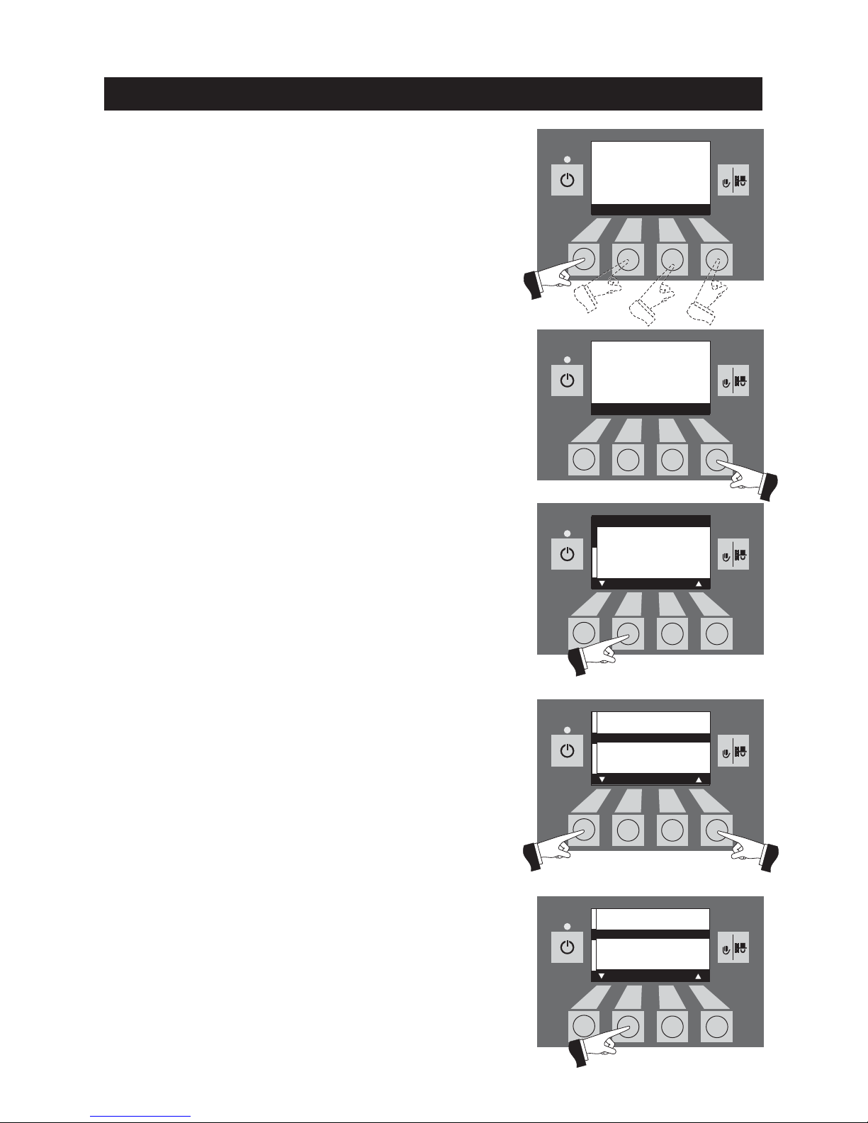
Pressing one of the four menu buttons switches the lighting on –
Fig. 73.
Fig. 73
Fig. 74
Fig. 75
Fig. 76
Press the Menu button – Fig. 74.
Confirm the selected menu item “Operator level” by pressing the
Choose button – Fig. 75.
The arrow buttons select the “Time profile feed” sub-menu – Fig.76.
Confirm the selected sub-menu “Time profile feed” by pressing the
Choose button – Fig. 77.
Fig. 77
Time
Feed operating mode
Time profile feed
Wand switching
Ash compr. time profile
Boiler cleaning
Choose Back
Boiler temperature
(Operating phases)
Lighting ON
42
°C
Boiler temperature
(Operating phases)
Info Menu
42
°C
Operator level
Service level
Choose Back
Time
Feed operating mode
Time profile feed
Wand switching
Ash compr. time profile
Boiler cleaning
Choose Back
Page 29
29
5s
RESET5sRESET5sRESET5sRESET5sRESET
“with enable time”
The start and end of the enable time can be set here in the “Time
profile feed” menu item if the “with enable time” setting is active
in the “Feed operating mode” menu item (see section 2.8.1.2).
Factory setting “feed enable time”: Start 07:00
End 22:00
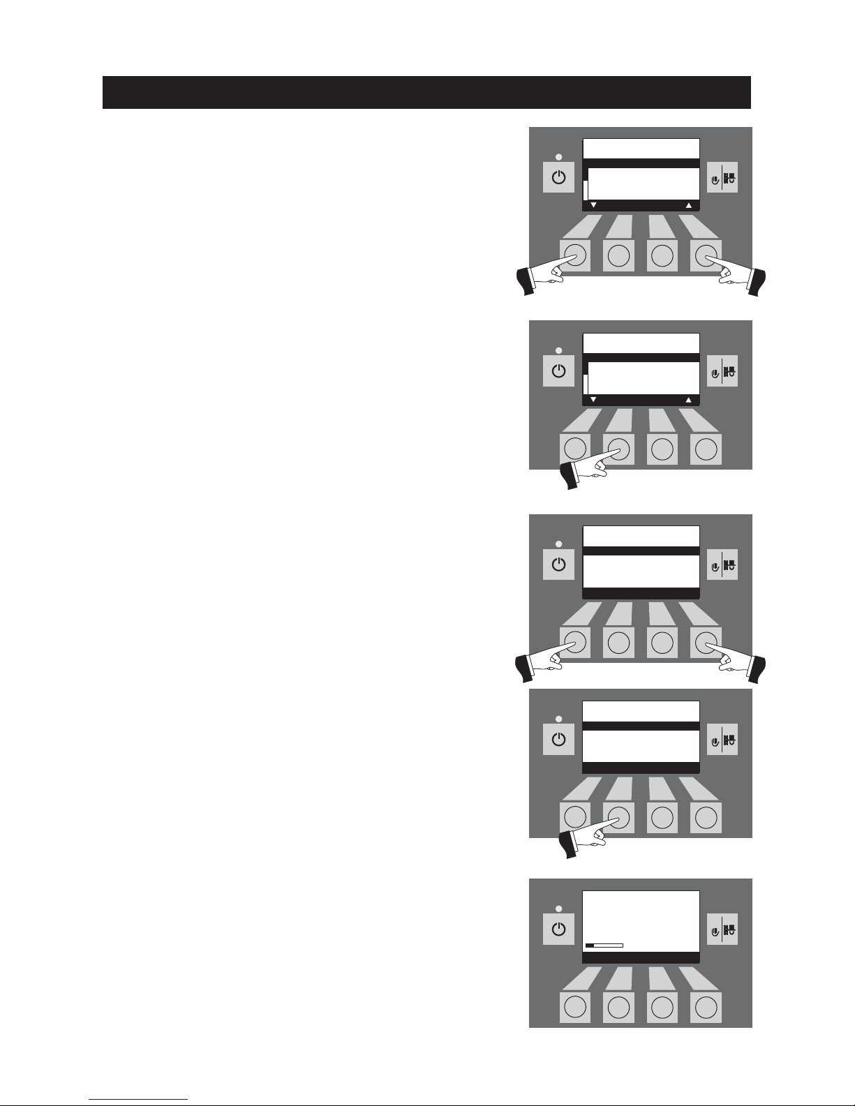
The arrow buttons select the “Start” or “End” time to be changed
– Fig. 78.
Confirm the selected time by pressing the Choose button – Fig. 79.
Fig. 78
Operation
Fig. 79
Fig. 80
Fig. 81
Fig. 82
Pressing the + or – buttons changes the time in 15 min steps –
Fig. 80.
Confirm the changed time by pressing the Ye s button – Fig. 81. The
display shows “Saving parameter value” for a few seconds (Fig. 82)
and then changes back to the previous level.
Feed with
enable time
Start 07:00
End 22:00
Choose Back
Feed with
enable time
Start 07:00
End 22:00
Choose Back
Feed with
enable time
Start 07:00
End 22:00
Save
––
Yes No
++
Feed with
enable time
Start 07:00
End 22:00
Save
––
Yes No
++
Saving parameter value
.....
(Animated symbol)
Page 30
30
5s
RESET
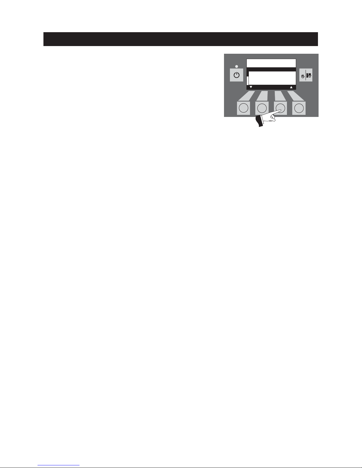
The menu item or sub-menu item is exited by pressing the Back
button (Fig. 83) or after a delay of 45 seconds.
Operation
Fig. 83
Feed with
enable time
Start 07:00
End 22:00
Choose Back
Page 31
31
5s
RESET
5s
RESET
5s
RESET5sRESET5sRESET
“without time control” or “switched off”
No setting is possible here in the “Time profile feed” menu item if
the “without time control” or “switched off” setting is active in the
“Feed operating mode” menu item (see section 2.8.1.2).
The menu item or sub-menu item is exited by pressing the Back
button (Fig. 88) or after a delay of 45 seconds.
Fig. 88
“with start time”
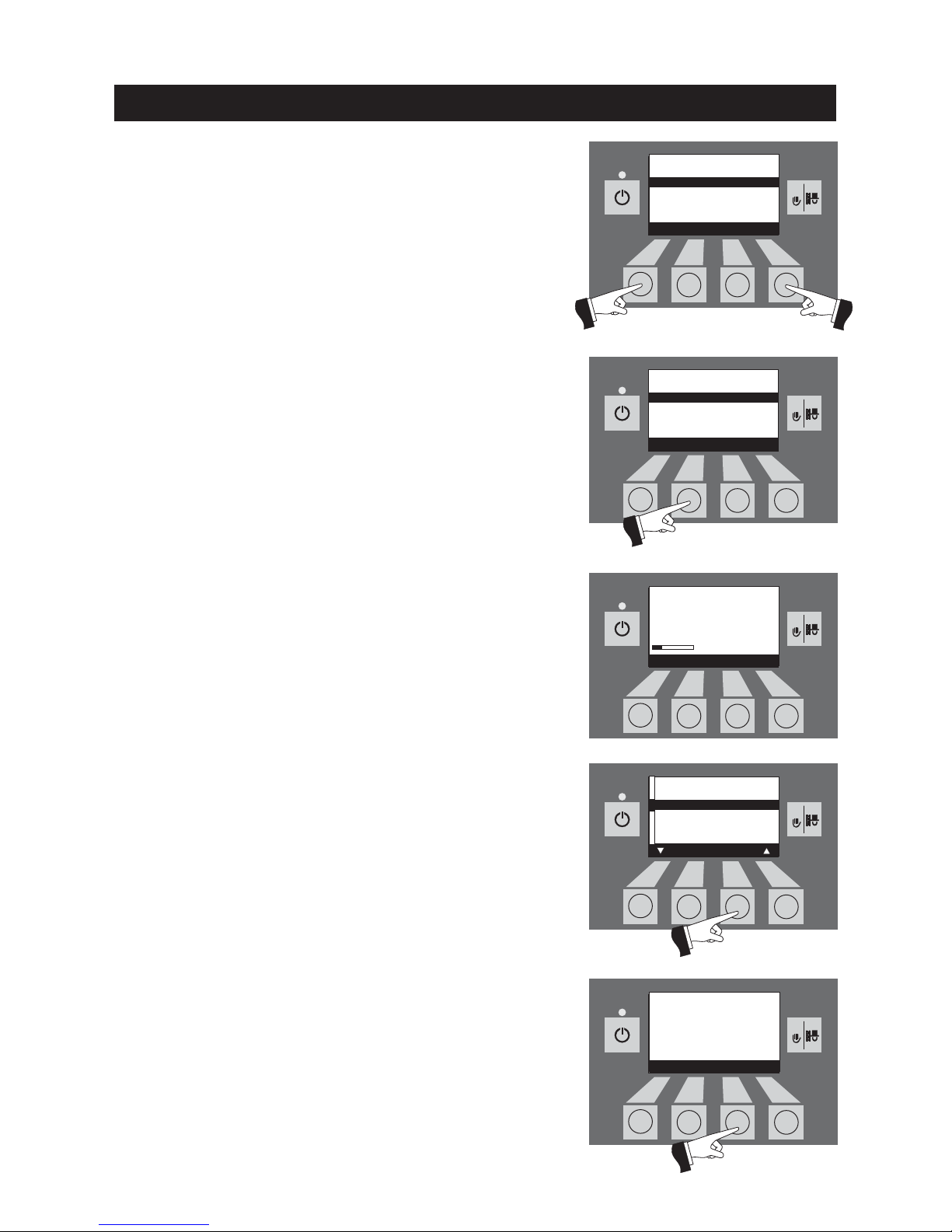
A time can be set here in the “Time profile feed” menu item for filling the reserve supply container if the “with start time” setting is
active in the “Feed operating mode” menu item (see section
2.8.1.2). The reserve supply container is filled every day at the set
time. Interim fills are also performed if the filling amount is not sufficient for 24 hours.
Factory setting “feed start time”: Start 20:00
Pressing the + or – buttons changes the time in 1 min steps –
Fig. 84.
Fig. 84
Operation
Fig. 85
Fig. 87
Confirm the changed time by pressing the Ye s button – Fig. 85. The
display shows “Saving parameter value” for a few seconds (Fig.
86) and then changes back to the previous level.
The menu item or sub-menu item is exited by pressing the Back
button (Fig. 87) or after a delay of 45 seconds.
Fig. 86
31
Feed with
start time
Start 20:00
Save
––
Yes No
++
Feed with
start time
Start 20:00
Save
––
Yes No
++
Time
Feed operating mode
Time profile feed
Wand switching
Ash compr. time profile
Boiler cleaning
Choose Back
Feed without
time control or
switched off
Back
Saving parameter value
.....
(Animated symbol)
Page 32
32
5s
RESET5sRESET
5s
RESET
5s
RESET5sRESET
32
Operation
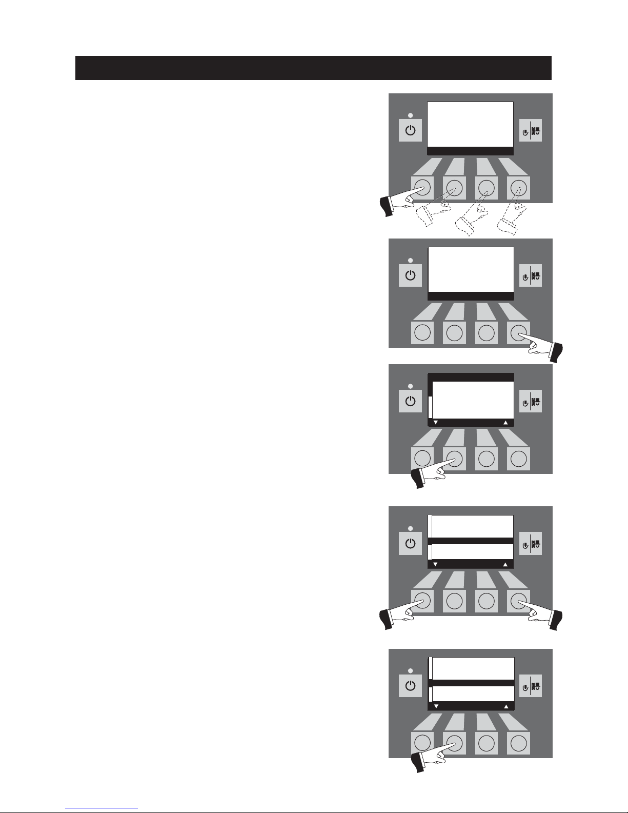
2.8.1.4 Setting wand switching
If FireWIN is equipped with a fully automated pellet feed, it is possible to set here which wand is used for sucking pellets from the
pellet storage room. There are four different setting options:
– automated: Removal from all 3 wands, automated
switching.
– Wand 1 only:Removal from wand 1 only, no switching
– Wand 2 only:Removal from wand 2 only, no switching
– Wand 3 only:Removal from wand 3 only, no switching
Note: If “Pellet feed system, operation with 2 wands” is set in the
service level, the option of “Removal from wand 3 only” is not displayed here.
Fig. 89
Fig. 90
Fig. 91
Fig. 92
Pressing one of the four menu buttons switches the lighting on –
Fig. 89.
Press the Menu button – Fig. 90.
Confirm the selected menu item “Operator level” by pressing the
Choose button – Fig. 91.
The arrow buttons set the “Wand switching” sub-menu – Fig. 92.
Confirm the selected “Wand switching” sub-menu by pressing the
Choose button – Fig. 93.
Fig. 93
Boiler temperature
(Operating phases)
Lighting ON
42
°C
Boiler temperature
(Operating phases)
Info Menu
42
°C
Operator level
Service level
Choose Back
Time
Feed operating mode
Time profile feed
Wand switching
Ash compr. time profile
Boiler cleaning
Choose Back
Time
Feed operating mode
Time profile feed
Wand switching
Ash compr. time profile
Boiler cleaning
Choose Back
Page 33
33
5s
RESET5sRESET5sRESET5sRESET
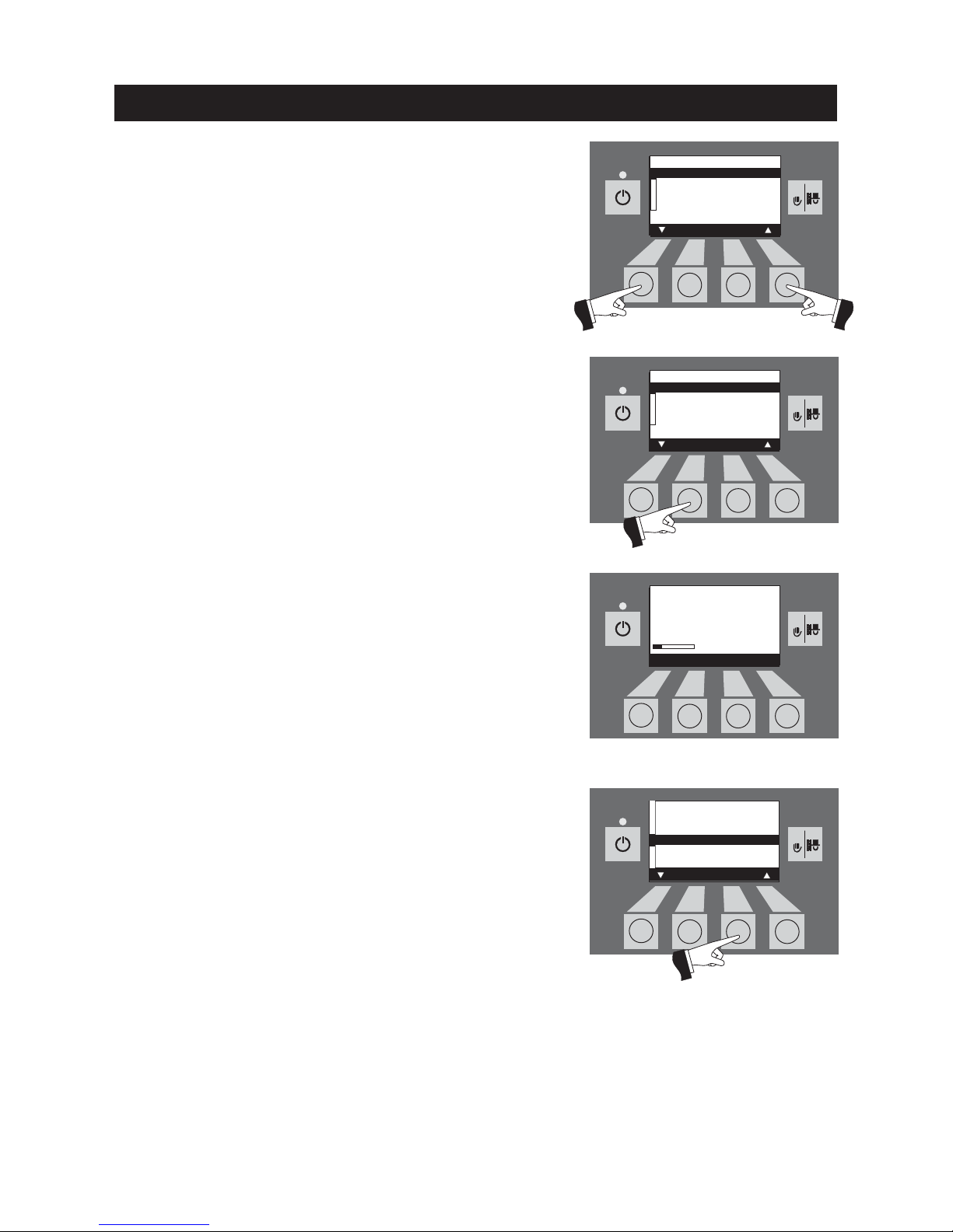
The arrow buttons set the wand switching – Fig. 94.
Fig. 94
Operation
Fig. 95
Fig. 97
Confirm the changed wand switching by pressing the Ye s button
– Fig. 95.
The display shows “Saving parameter value” for a few seconds
(Fig. 96) and then changes back to the previous level.Tip: This menu
item is also needed for “Pellet store maintenance” in order to
switch off one specific wand at a time – see also the pellet store
planning documents.
The menu item or sub-menu item is exited by pressing the Back
button (Fig. 97) or after a delay of 45 seconds.
Fig. 96
Wand switching
automated
Wand 1 only
Wand 2 only
Wand 3 only
Save
Yes No
Saving parameter value
.....
(Animated symbol)
Wand switching
automated
Wand 1 only
Wand 2 only
Wand 3 only
Save
Yes No
Time
Feed operating mode
Time profile feed
Wand switching
Ash compr. time profile
Boiler cleaning
Choose Back
Page 34
34
5s
RESET5sRESET5sRESET5sRESET5sRESET
2.8.1.5 Ash compression time profile
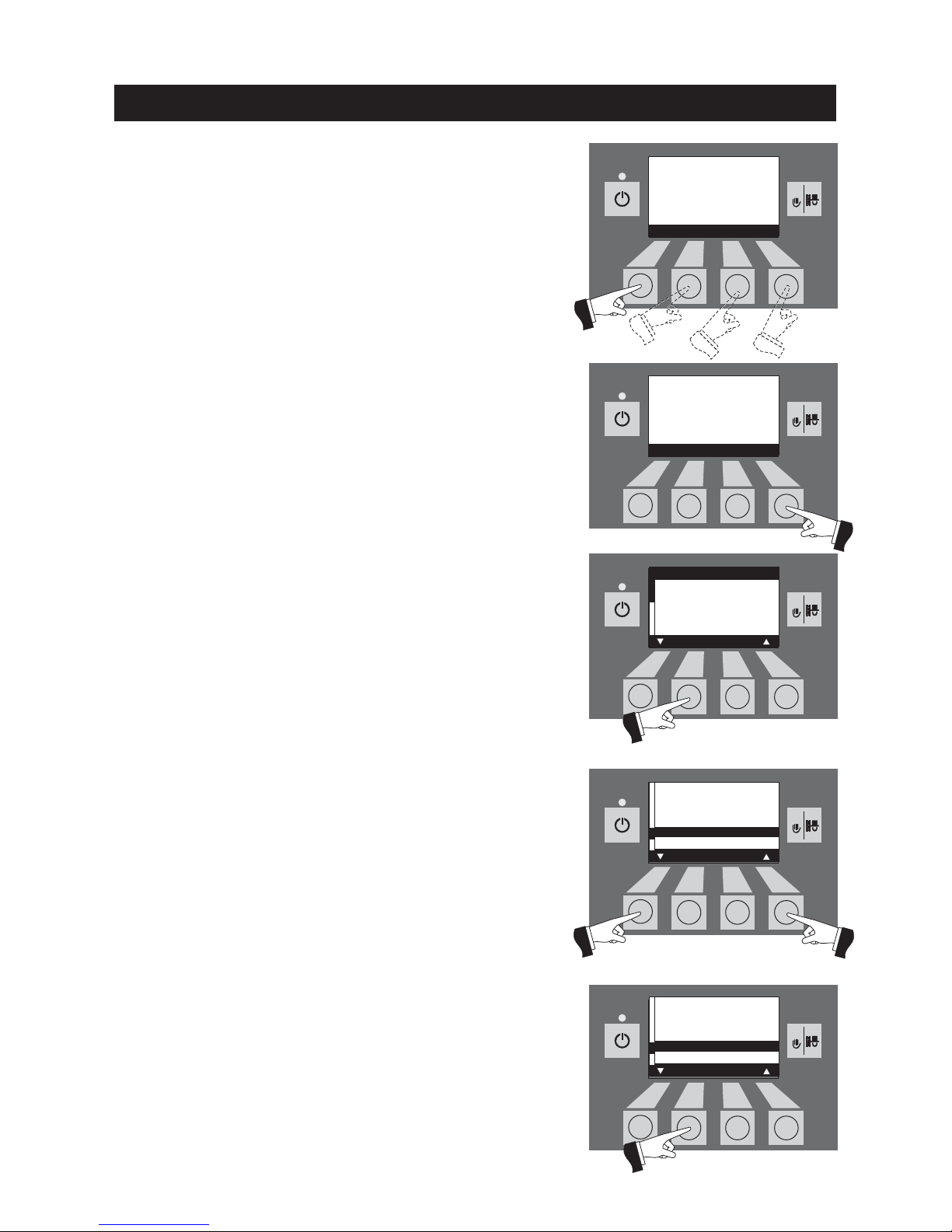
The ash in the ash pan is only compressed at the 2 set start times
and when approx. 15 kg of fuel has been consumed. The start times
can be set in steps of 15 minutes (start time 1 and start time 2).
Factory setting: Start time 1: 08:00
Start time 2: 22:00
Pressing one of the four menu buttons switches the lighting on –
Fig. 98.
Fig. 98
Fig. 99
Fig. 100
Fig. 101
Press the Menu button – Fig. 99.
Confirm the selected menu item “Operator level” by pressing the
Choose button – Fig. 100.
The arrow buttons select the “Time profile ash compr.” sub-menu
– Fig. 101.
Confirm the selected sub-menu “Time profile ash compr.” by pressing the Choose button – Fig. 102.
Fig. 102
Time
Feed operating mode
Time profile feed
Wand switching
Ash compr. time profile
Boiler cleaning
Choose Back
Boiler temperature
(Operating phases)
Lighting ON
42
°C
Boiler temperature
(Operating phases)
Info Menu
42
°C
Operator level
Service level
Choose Back
Operation
Time
Feed operating mode
Time profile feed
Wand switching
Ash compr. time profile
Boiler cleaning
Choose Back
Page 35
35
5s
RESET
5s
RESET
5s
RESET5sRESET5sRESET
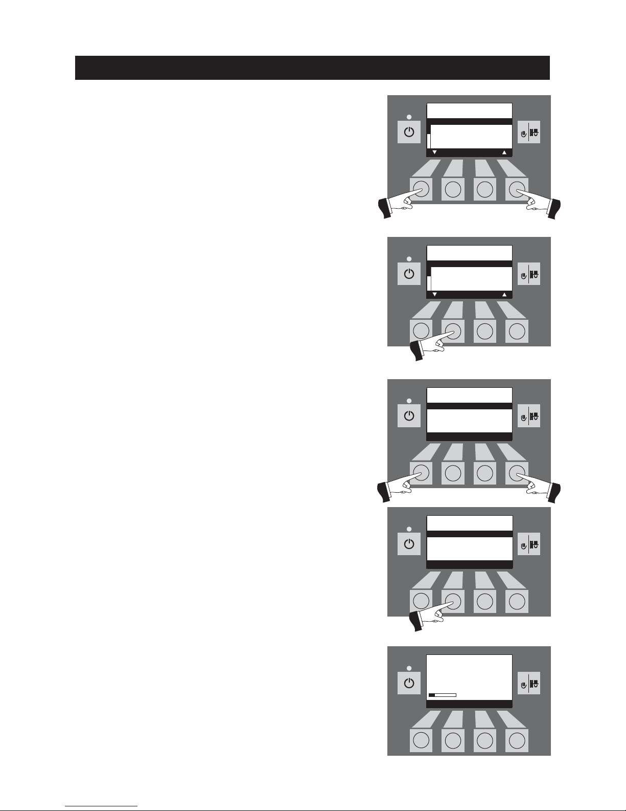
The arrow buttons select the start time 1 or 2 to be changed –
Fig. 103.
Confirm the selected start time by pressing the Choose button –
Fig. 104.
Fig. 103
Fig. 104
Fig. 105
Fig. 106
Fig. 107
Pressing the + or – buttons changes the time in 15 min steps –
Fig. 105.
Confirm the changed time by pressing the Ye s button – Fig. 106.
The display shows “Saving parameter value” for a few seconds
(Fig. 107) and then changes back to the previous level.
Start times for
ash compression
Start time 1 08:00
Start time 2 22:00
Choose Back
Start times for
ash compression
Start time 1 08:00
Start time 2 22:00
Save
––
Yes No
++
Saving parameter value
.....
(Animated symbol)
Operation
Start times for
ash compression
Start time 1 08:00
Start time 2 22:00
Choose Back
Start times for
ash compression
Start time 1 08:00
Start time 2 22:00
Save
––
Yes No
++
Page 36
36
Operation
5s
RESET5sRESET5sRESET5sRESET5sRESET
2.8.1.6 Boiler cleaning – Resetting the cleaning
request
After boiler cleaning has been performed, the operating hours
counter for boiler cleaning must be reset.
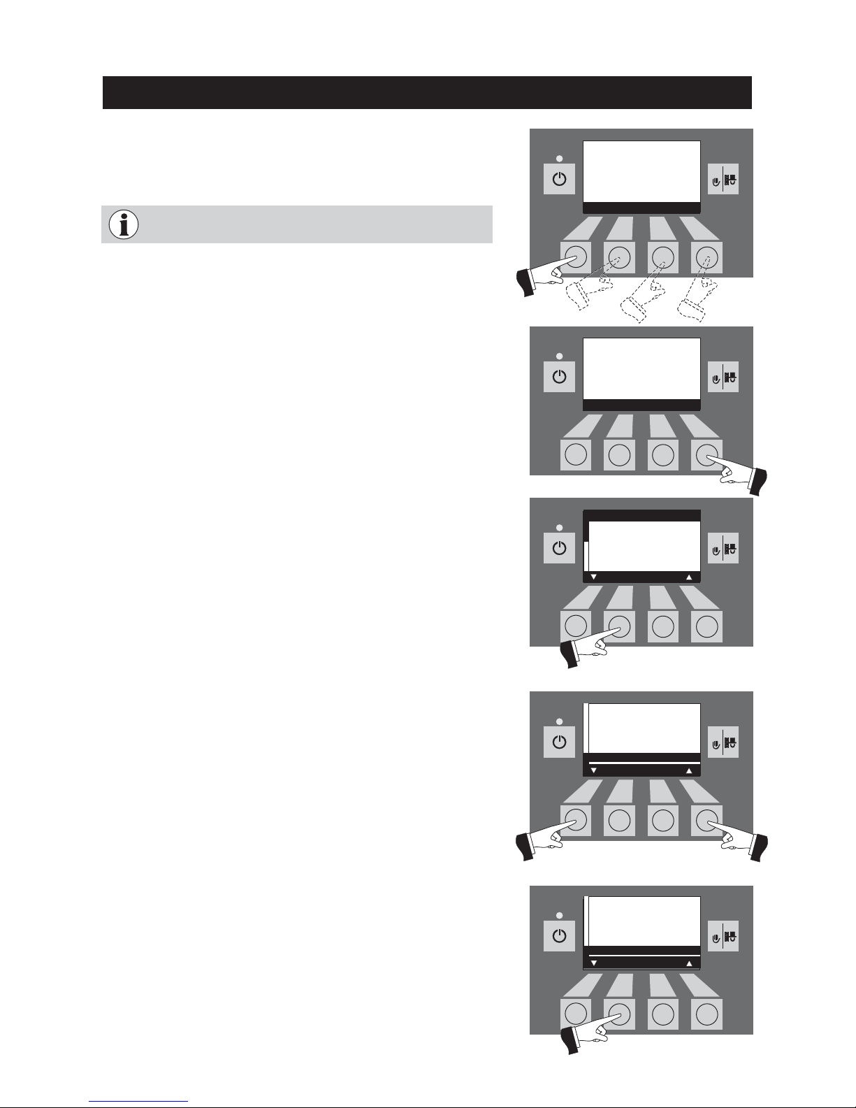
Fig. 108
Fig. 109
Fig. 110
Fig. 111
Press the Menu button – Fig. 109.
Confirm the selected menu item “Operator level” by pressing the
Choose button – Fig. 110.
The arrow buttons set the “Boiler cleaning” sub-menu – Fig. 111.
Confirm the selected “Boiler cleaning” sub-menu by pressing the
Choose button – Fig. 112.
Fig. 112
Boiler temperature
(Operating phases)
Lighting ON
42
°C
Boiler temperature
(Operating phases)
Info Menu
42
°C
Operator level
Service level
Choose Back
Time
Feed operating mode
Time profile feed
Wand switching
Ash compr. time profile
Boiler cleaning
Choose Back
Time
Feed operating mode
Time profile feed
Wand switching
Ash compr. time profile
Boiler cleaning
Choose Back
Pressing one of the four menu buttons switches the lighting on –
Fig. 108.
Without cleaning (see section 3.4), the operating hours
counter for boiler cleaning cannot be reset.
Page 37
5s
RESET5sRESET
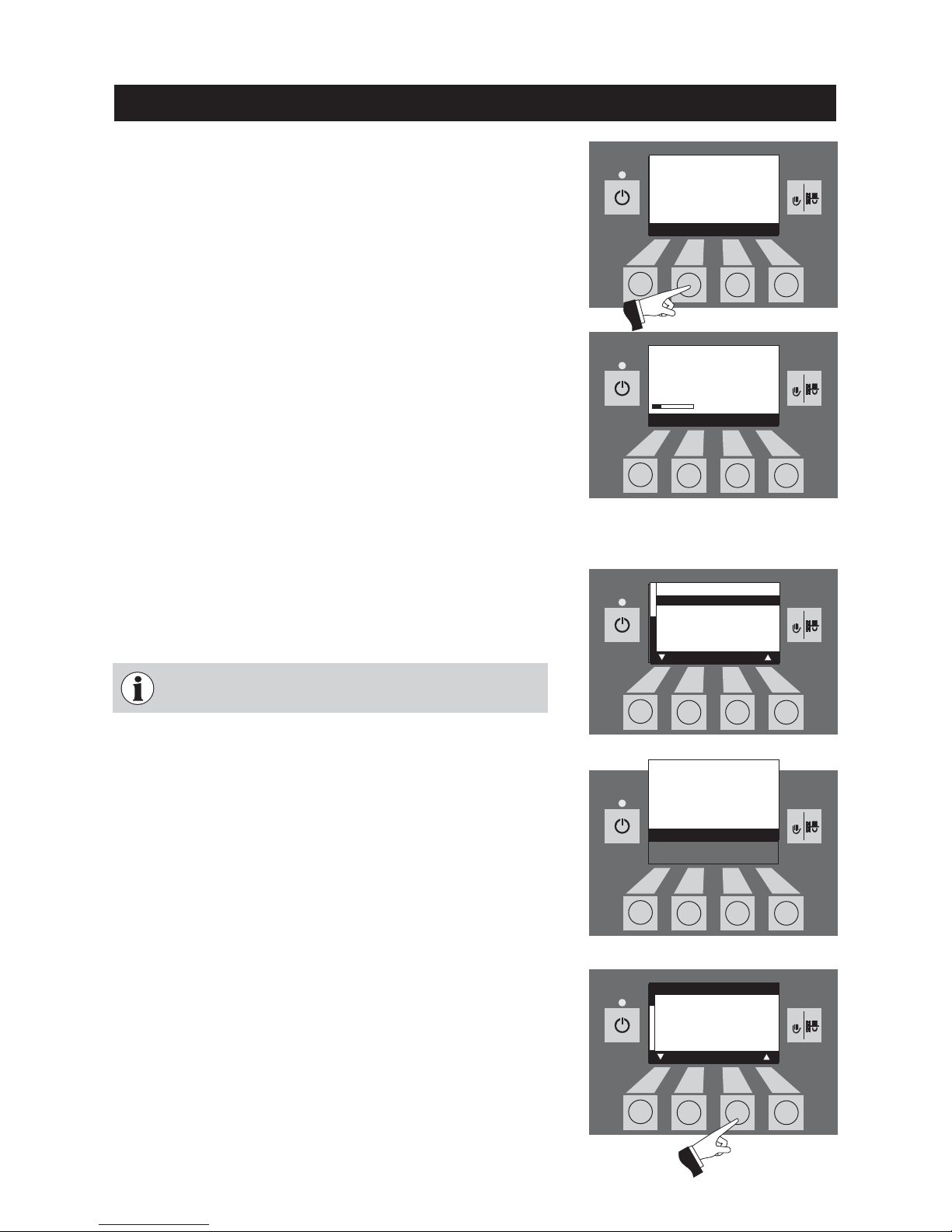
Pressing the Ye s button resets the operating hours counter for boiler
cleaning – Fig. 113.
The display shows “Saving parameter value” for a few seconds
(Fig. 114) and then changes back to the previous level.
Fig. 113
Fig. 114
Has boiler and
burner cleaning
been performed?
Confirm
––
Yes Back
++
Saving parameter value
.....
(Animated symbol)
Operation
37
5s
RESET
5s
RESET
5s
RESET
2.8.2 Service level
System parameters, start-up and actuator test can be displayed,
performed and/or modified on the Service level.
Fig. 116
Fig. 115
Changes on the Service level may be performed only by
trained service personnel (directions for setting, see the
FireWIN Installation instructions).
Fig. 117
The menu item or sub-menu item is exited by pressing the Back but-
ton (Fig. 117) or after a delay of 45 seconds.
Operator level
Service level
Choose Back
Service level only
for trained
service personnel
5 s
Parameters
Start-up
Actuator test
Choose Back
Page 38
38
Operation
2.9 Heating system operation
2.9.1 FireWIN with MES system control
Switching on – automatic operation:
1. Press the ON/OFF button on the InfoWIN panel, the display lighting is switched on, the signal lamp lights green
and a self-test is performed (see also section 2.5.2). After a successful self-test and if a setpoint is transferred
by the system control, the FireWIN automatically starts operation.
2. Set the operating mode switch(es) on the MES control module(s) to “Automatic operation”. The system oper-
ation (setting temperatures and operating times) is performed using the analogue or digital user module
(installed in the living area) – for more details, please refer to the MES and user module instructions.
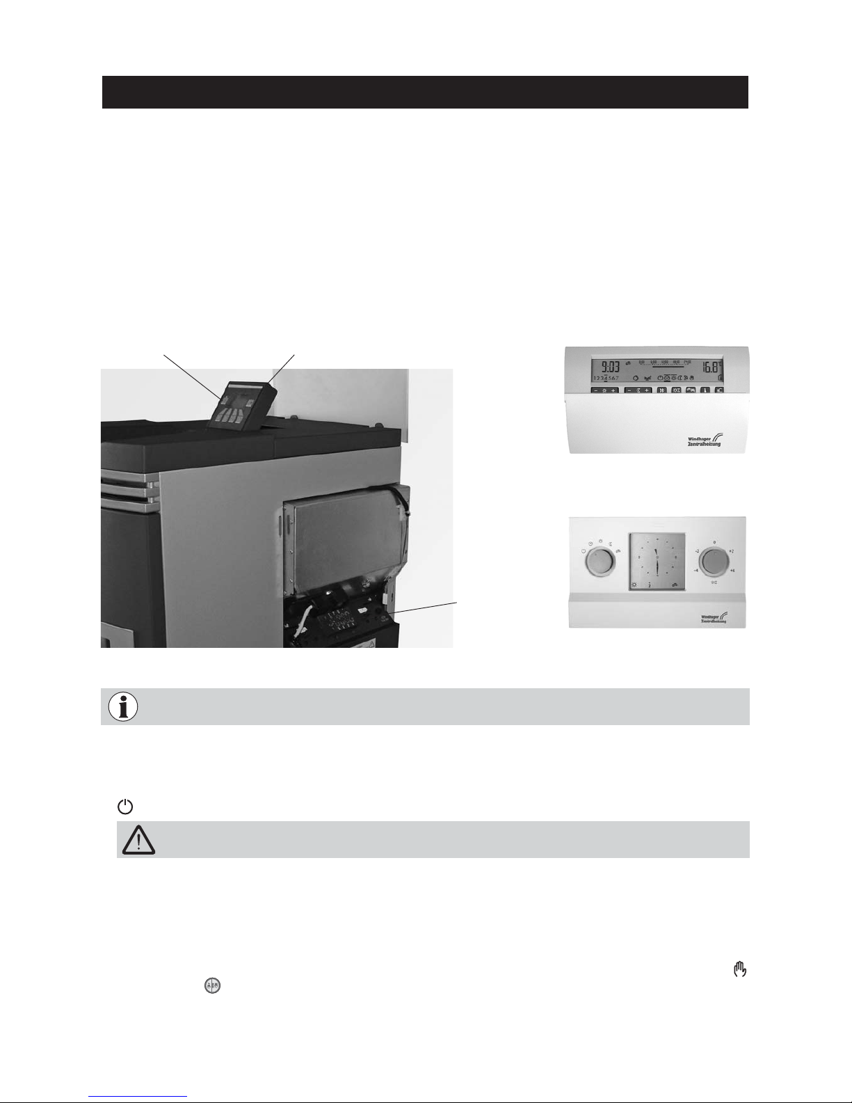
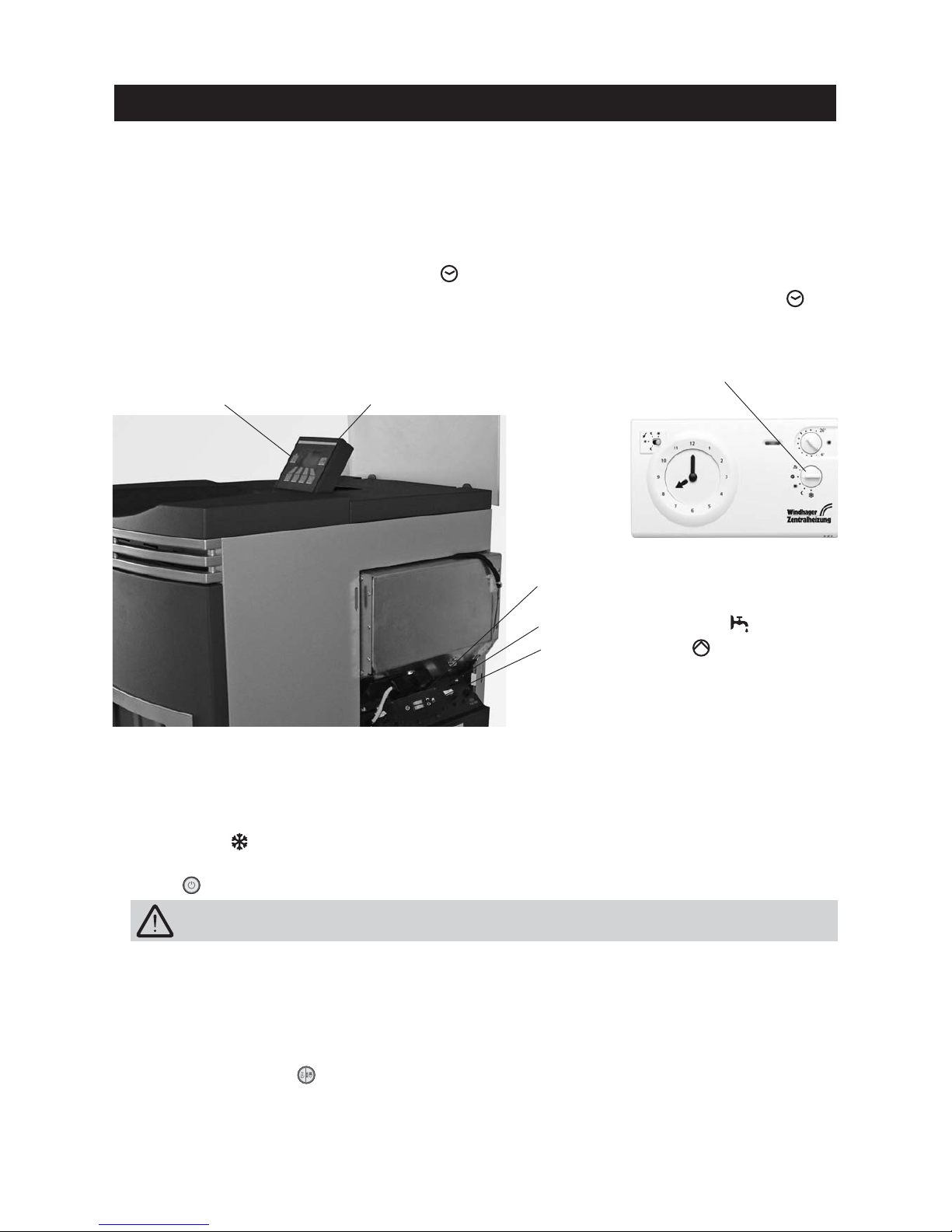
Fig. 118 FireWIN with MES system control
Digital user module FB 5210
Analogue user module FB 5410
ON/OFF button
Operating mode
switch
Switching off:
1. Set the operating mode to “Standby” using the analogue or digital user module (installed in the living area).
2. If the boiler has been out of service for an extended period during the summer months, press the ON/OFF button
on the InfoWIN unit.
Flue cleaning function:
This is operated using the InfoWIN unit – see section 2.5.6.
Emergency operation:
In the event the system control fails, selecting the “Manual operation” mode using the MES control module
and InfoWIN unit (see section 2.5.5) will activate emergency operation to maintain heat and hot water.
For operation of the MES and related user modules, please see their respective Operating instructions.
The anti-freeze function is not active when the boiler is shut off.
InfoWIN operating unit
Page 39
39
Operation
2.9.2 FireWIN with REG standard control
Switching on – automatic operation:
1. Press the ON/OFF button on the InfoWIN panel, the display lighting is switched on, the signal lamp lights
green and a self-test is performed (see also section 2.5.2). After a successful self-test and if a setpoint is transferred by the system control, the FireWIN automatically starts operation.
2. Set both manual switches to the “Automatic” position.
3. Set the operating mode switch on the REG standard control unit RAM 786 to “Automatic operation” . The
REG standard control unit RAM 786 (installed in the living area) is used to operate the system (set the desired
temperature and operating times) – please refer to the separate Operating instructions.
Fig. 119 BioWIN with REG standard control
REG standard control RAM 786
Operating mode switch
Switching off:
1. Set “Standby” operating mode on the REG standard control unit (installed in the living area).
2. If the boiler has been out of service for an extended period during the summer months, press the ON/OFF
button on the InfoWIN unit.
Flue cleaning function:
This is operated using the InfoWIN unit – see section 2.5.6.
Emergency operation:
In the event the system control fails, setting the two manual switches on the boiler control panel and using the
button on the InfoWIN unit (see section 2.5.5) will activate emergency operation to maintain heat and hot
water.
The anti-freeze function is not active when the boiler is shut off.
Manual switch for hot water tank
Manual switch for heating
Automatic operation
ON/OFF button InfoWIN operating unit
Page 40

40
Operation
How to switch to emergency (manual) operation
Heating emergency operation:
1. There must be power to the boiler. The unit is switched on (otherwise, press the ON/OFF button on the
InfoWIN unit).
2. Select “Manual operation” on the InfoWIN unit – see section 2.5.5.
3. Set the manual switch to the “Heating manual operation” position.
4. Also set the motorised mixing valve to manual operation and select the desired flow temperature. The boiler temperature will be maintained at the selected temperature (60 to 75 °C). Exercise caution if you have
underfloor heating.
Emergency operation of boiler reservoir with feed pump:
1. There must be power to the boiler. The unit is switched on (otherwise, press the ON/OFF button on the
InfoWIN unit).
2. Select “Manual operation” on the InfoWIN unit – see section 2.5.5.
3. Set the manual switch to the “Hot water tank manual operation” position.
4. Once the desired hot water temperature has been reached, set the manual switch to the “Hot water tank
automatic operation” position.
Emergency operation of boiler reservoir with charging valve:
1. There must be power to the boiler. The unit is switched on (otherwise, press the ON/OFF button on the
InfoWIN unit).
2. Select “Manual operation” on the InfoWIN unit – see section 2.5.5.
3. Set both manual switches to the “Manual operation” and position.
Page 41
41
3.1 Care of the front window, cladding and keyboard foil
The front window is equipped with a special back ventilation. This ensures that the window remains clean for
a relatively long time. Nevertheless, light deposits formed by ash constituents will form on the inside of the
glass window (inside window). This causes the viewing window to be obscured. This obscuring has no effect
whatsoever on the quality of combustion. The coating can be removed with the door open using water and a
cleaning cloth when the glass is cold. If the glass window is very dirty, moisten the cleaning cloth and dip it in
ash first, then clean.
Tip: Position newspaper or the like to protect the floor against fly ash before opening the combustion chamber
door.
If you wish to enjoy a completely clear view of the fire through the glass window, perform this cleaning about
every 1 or 2 days according to the amount of use during the heating season.
Also clean the cladding and the keyboard foil with a moist cloth as needed. In the event of heavy soiling, use
soapy water or diluted suds (do not use strong cleaners or sharp cleaning instruments).
3.3 Overview of intervals between maintenance
A clean boiler saves fuel and protects the environment. Fly ash and combustion residues must be cleaned off the
pellet flue-connected boiler at regular intervals. Therefore always clean your boiler as required!
In addition to cleaning, annual maintenance is required. This is performed
by WINDHAGER Customer Service or
the customer service PARTNERS and is a prerequisite of the guarantee limitations.
The cleaning and ash removal intervals may be reduced or extended depending on the pellets used (e.g. ash
proportion), the power consumed by the heating system (frequently switching on and off) and the boiler size
of the FireWIN (9 to 12 kW).
The FireWIN is equipped with a cleaning interval display. The cleaning request for the combustion chamber
and burner pot is displayed on the InfoWIN and must be reset after cleaning has finished – see section 2.8.1.6.
Tip: The intervals between maintenance can be determined according to the amount of pellets consumed. Therefore, read out and note down the pellet consumption* on the InfoWIN (section 2.7) in order to determine the
individual intervals that apply to you.
Care, cleaning and maintenance
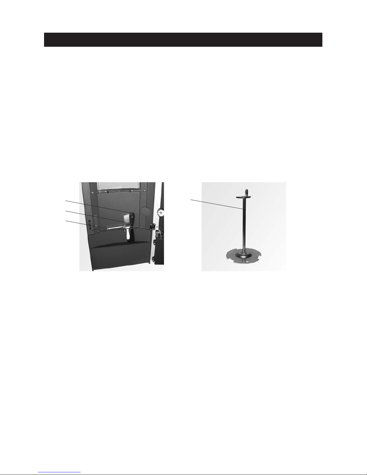
3.2 Cleaning and operating implements
1 . . . . .Spatula
2 . . . . .Cleaning brush
3 . . . . .Allen key for cleaning heating surfaces
4 . . . . .Cone removal tool
Fig. 120 Cleaning and operating imple-
ments in the cladding door
* The pellet consumption is a calculated value and can differ from the actual value by ±15%.
Fig. 121 Cone removal tool and grate
removal tool
1
2
3
4
Page 42

42
Maintenance intervals FireWIN Klassik FireWIN Premium FireWIN Exklusiv
Depending on pellet con-
sumption
approx. every 37 kg
(~ 20 operating hours)
See section 3.3
Fill pellets into
the reserve supply container
– –
Depending on pellet con-
sumption
approx. every 400 kg
(~ 250 operating hours)
See section 3.3
Empty the ash pan(s)
Operate the heating surface
cleaning lever
Frequent use of the lever
increases efficiency
Empty the ash pan(s)
Operate the heating surface
cleaning lever
Frequent use of the lever
increases efficiency
–
Depending on pellet con-
sumption
approx. every 800 kg
(~ 500 operating hours)
See section 3.4
Check the combustion
chamber and burner pot,
clean if necessary
Empty the ash pan(s)
Operate the heating surface
cleaning lever
Frequent use of the lever
increases efficiency
Check the combustion
chamber and burner pot,
clean if necessary
Empty the ash pan(s)
Operate the heating surface
cleaning lever
Frequent use of the lever
increases efficiency
Check the FireWIN reserve
supply container, if necessary
remove ash
–
Depending on pellet con-
sumption
approx. every 1200 kg
(~ 750 operating hours with
average
70% boiler output)
See section 3.4
– –
Check the combustion
chamber and burner pot,
clean if necessary
Check reserve supply
container FireWIN, if
necessary remove ash
Empty the ash pan(s)
at least once per heating
season
See section 3.5
Clean the top heating
surfaces and linkage
Clean blower wheel and
blower box
Clean exhaust pipe to flue
Check the reserve supply
container, if necessary
remove dust
Clean the top heating
surfaces and linkage
Clean blower wheel and
blower box
Clean exhaust pipe to flue
Remove dust from reserve
supply container and
clean filter
Check the storage room or
storage container, if necessary
remove dust
Clean the top heating
surfaces and linkage
Clean blower wheel and
blower box
Clean exhaust pipe to flue
Remove dust from reserve
supply container and
clean filter
Check the storage room or
storage container, if necessary
remove dust
Care, cleaning and maintenance
Page 43
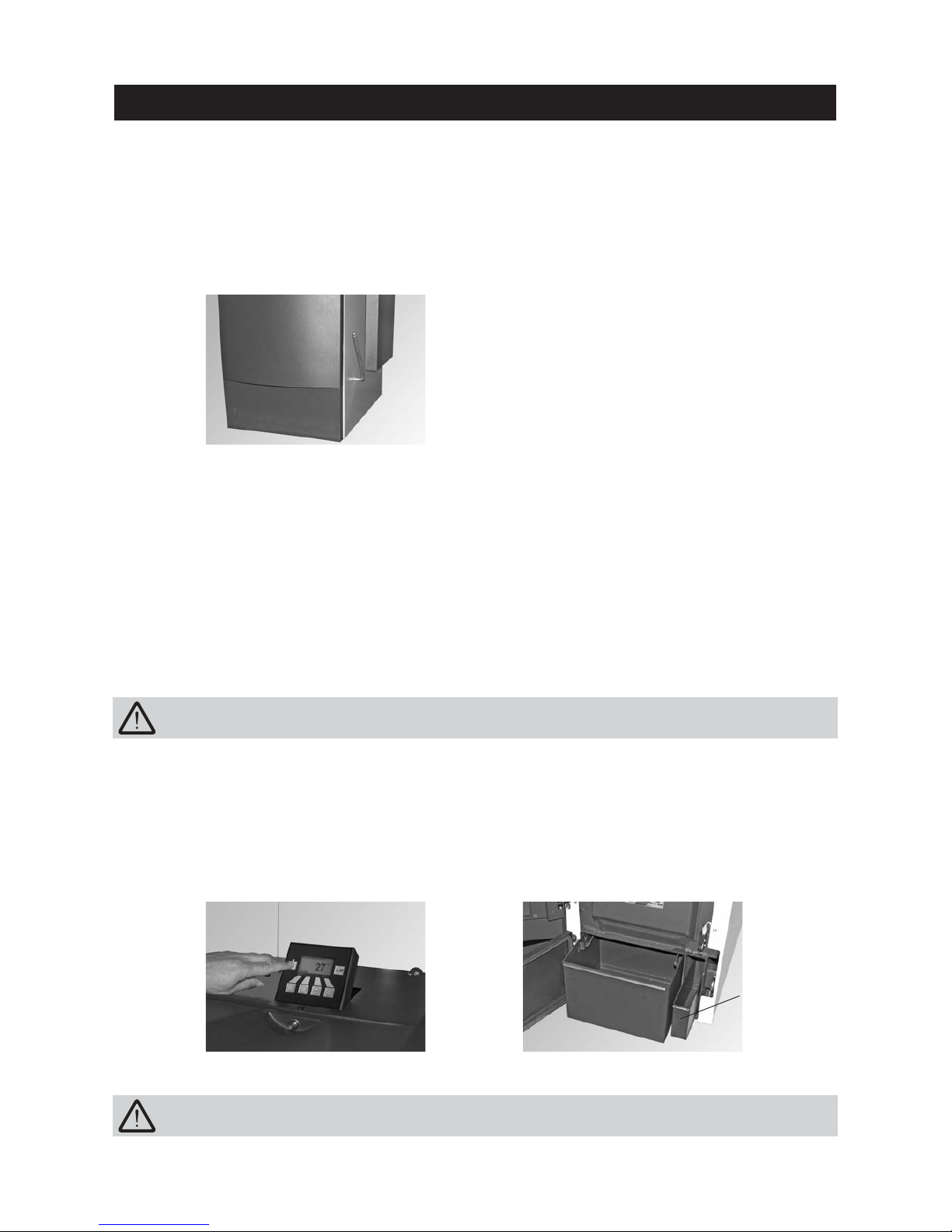
43
Tip: Position newspaper or the like to protect the floor against fly ash before opening the combustion chamber
door.
– Open the cladding door and ash door, empty the ash pan under the combustion chamber and the ash pan
for the heating surfaces (accessory) or remove the ash from the duct – Fig 124.
Assembly:
– Push in the ash pan(s), close the doors.
– Switch the FireWIN back on with the ON/OFF button.
Fig. 122 Connect the lever and operate it
Fig. 123 Switching off FireWIN Fig. 124 Empty the ash pan(s) or remove the
ash from the heating surface duct
Always switch the boiler off first with the ON/OFF button (Fig. 123) and wait until burnout mode has
finished. Do not open the combustion chamber and ash door during operation.
3.5 Ash pan, ash on heating surface
Care, cleaning and maintenance
3.4 Heating surfaces
FireWIN Klassik and Premium
Optimum efficiency is achieved when the heating surfaces are cleaned as often as possible using the cleaning
lever. However, the cleaning lever should be connected on the right side and moved backwards and forwards
several time at the latest before the ash pan is removed or the ash removed from the heating surfaces – Fig. 122.
Ash pan for
heating surfaces
(accessories)
When emptying the ash pan(s), remember that there could still be embers in the ash!
FireWIN Exklusiv
The heating surfaces are cleaned fully automatically after the set start times (see section 2.8.1.5) and when
approx. 15 kg of fuel has been consumed – on average 1x a day.
Page 44
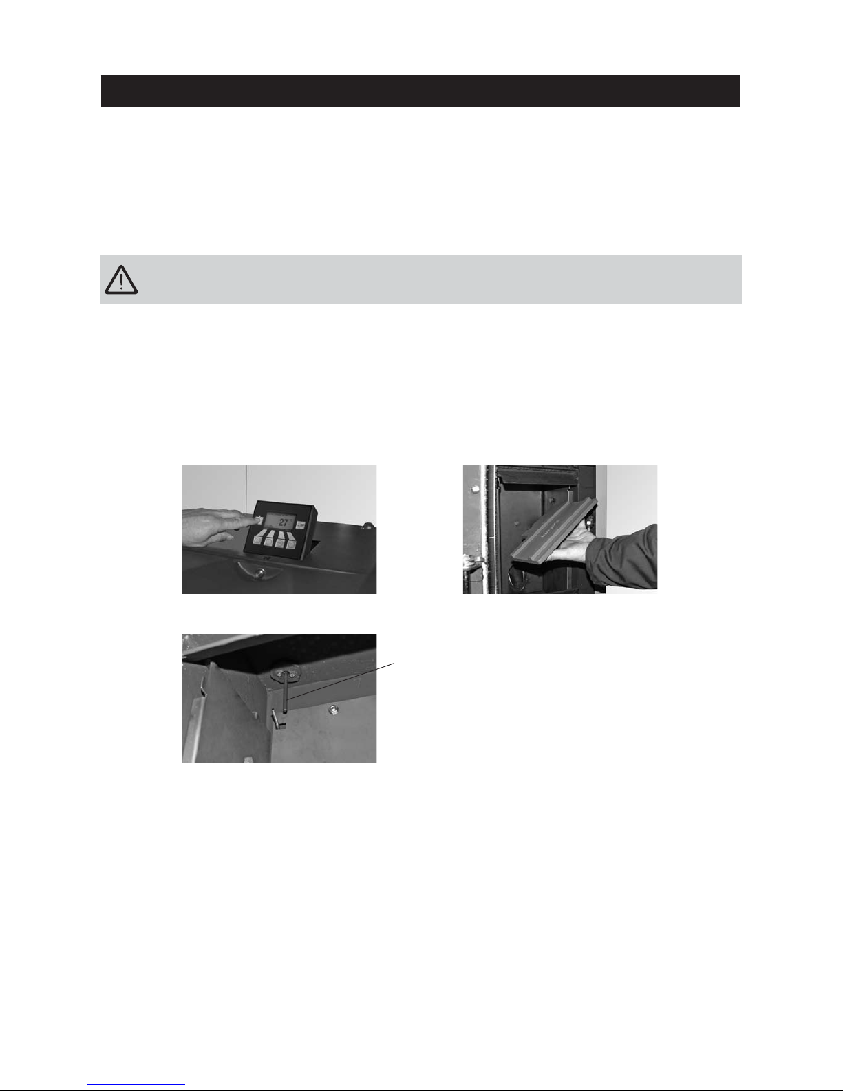
44
Care, cleaning and maintenance
Do not open the combustion chamber door during operation. Always switch the boiler off first with the
ON/OFF button (Fig. 125) and wait until burnout mode has finished. It is essential to let the boiler cool
down before cleaning.
– Open the combustion chamber door, lift the baffle plate at the right and guide it out at an angle with the left
side downwards – Fig. 126, Taking out the baffle plate and removing fly ash
– If necessary, remove fly ash from the temperature sensor with a cleaning brush. The temperature sensor is
located at the top left of the combustion chamber behind the baffle plate – Fig. 127.
Assembly:
By working through these steps in reverse order.
Temperature sensor
Fig. 126 Removing and cleaning the baffle plate
Fig. 127 Cleaning the temperature sensor
(with cleaning brush)
Fig. 125 Switching off FireWIN
3.6 Combustion chamber (baffle plate, temperature sensor)
The FireWIN is equipped with a cleaning interval display. The cleaning request for the combustion chamber
and burner pot is displayed on the FireWIN Klassik and Premium after 500 operating hours, on the FireWIN
Exklusiv after 750 operating hours and must be reset after cleaning has finished – see section 2.8.1.6. “Boiler
cleaning – Resetting the cleaning request”.
Page 45
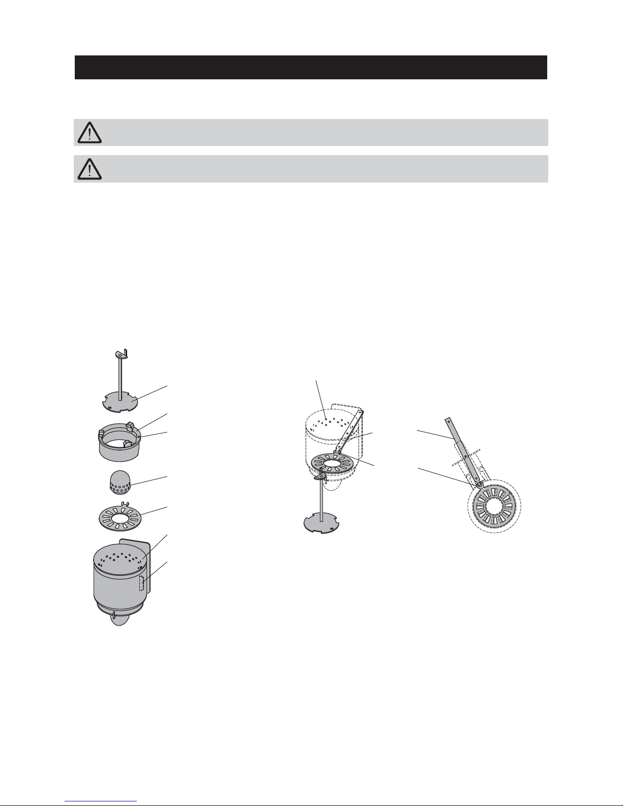
45
Care, cleaning and maintenance
Assembly:
– Insert the grate plate, making sure the projection of the grate plate projects through the opening of the burn-
er pot into the shaker lever – Figs. 129, 130.
– Place the cone into the burner pot using the removal tool. The grooves in the cone must project into the
lock of the burner – Fig. 128.
Important: Before inserting the primary air pin, once again vacuum out the primary air tube in the middle
of the burner pot. Make sure there is no debris in the tube (damage to the ignition element!).
– Insert the primary air pin.
Burner pot
Removal tool
Cone
Guide groove
for the lock
in the burner pot
Primary air pin
Grate plate
Burner pot
Lock
for cone
Fig. 128 Burner pot
Fig. 129 Removing the grate disc
If the level of combustion residue in the burner pot is more than 4 cm above the grate plate, perform cleaning
as follows:
– Lift out the cone using the removal tool – Fig. 128.
– Use the spatula to scrape off the deposits from all sides of the cone, however in particular on the underside.
– Vacuum out the burner pot, remove the primary air pin and carefully clean the holes with a small screw-
driver or drill bit if necessary (holes must be clear).
– Lift the grate plate from below using the removal tool and remove it (Fig. 129), scrape off ash residues from
the top and bottom of the grate plate and from the hole in the middle using the spatula to clean it.
– Use a spatula to scrape the edges out clean all round the inside of the burner pot at the bottom. All sec-
ondary air holes must be clear, clean them with a small screwdriver or drill bit if necessary.
– Remove combustion residues from the burner pot and the grate with a spatula and clean with a vacuum clean-
er. Vacuum the ash out of the primary air tube (in the middle of the burner pot).
Do not open the combustion chamber door during operation. Always switch the boiler off first with the ON/OFF
button and wait until burnout mode has finished. It is essential to let the boiler cool down before cleaning.
Fig. 130 Installing the grate disc
– view from above
Secondary air holes
Shaker lever
Projection
of the
grate plate
Before cleaning with a vacuum cleaner, check that there are no longer any embers in the combustion
residue!
Page 46
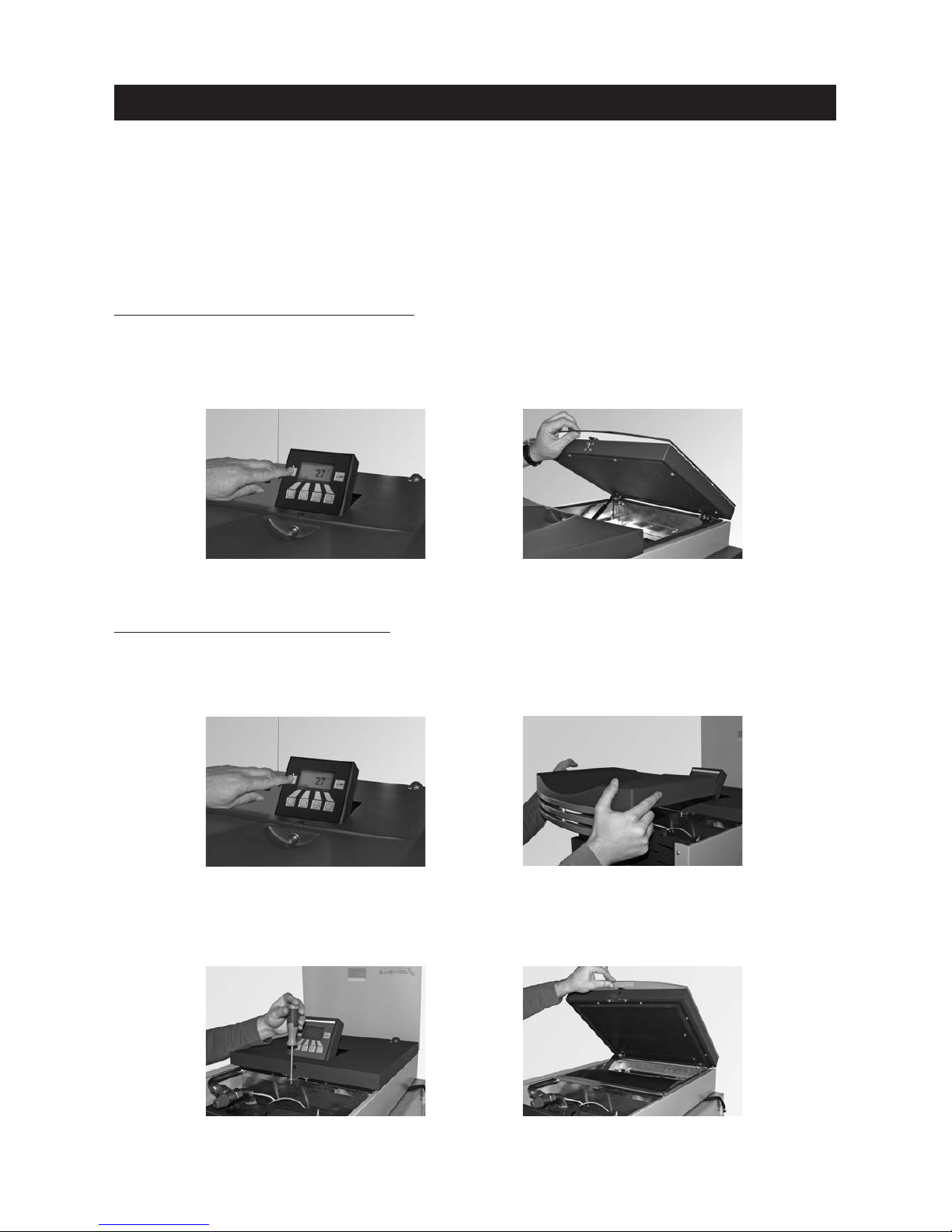
46
Care, cleaning and maintenance
3.7 FireWIN reserve supply container
It is necessary to clean the reserve supply container if too much dust has collected on the sides or at the opening above the auger, or there are foreign bodies in the reserve supply container. In order to be able to check
this, there must not be any pellets in the reserve supply container. Therefore, allow the pellets in the reserve
supply container to be consumed or, in the case of FireWIN with automated feed, switch off the feed on the
day before (see section 2.8.1.2 Setting the feed operating mode).
Cleaning
FireWIN
wwiitthhoouutt
fully automated pellet feed:
– Switch off the FireWIN with the ON/OFF button on the InfoWIN (Fig. 131) and wait until the display has gone
out.
– Close the glass cover – danger of damage – Fold open the cover of the reserve supply container (Fig. 132)
and vacuum out the pellets, dust or foreign bodies through the mesh using a vacuum cleaner.
Fig. 131 Switching off FireWIN
Fig. 132 Folding open the cover
FireWIN
wwiitthh
fully automated pellet feed:
– Switch off the FireWIN with the ON/OFF button on the InfoWIN (Fig. 133) and wait until the display has gone
out.
– Remove the cover at the front – Fig. 134.
Fig. 133 Switching off FireWIN
Fig. 134 Folding open the cover
Fig. 135 Switching off FireWIN
Fig. 136 Folding open the cover
– Remove the screw on the front of the reserve supply container cover (Fig. 135), close the glass cover – dan-
ger of damage – and open the reserve supply container cover – Fig. 136.
Page 47
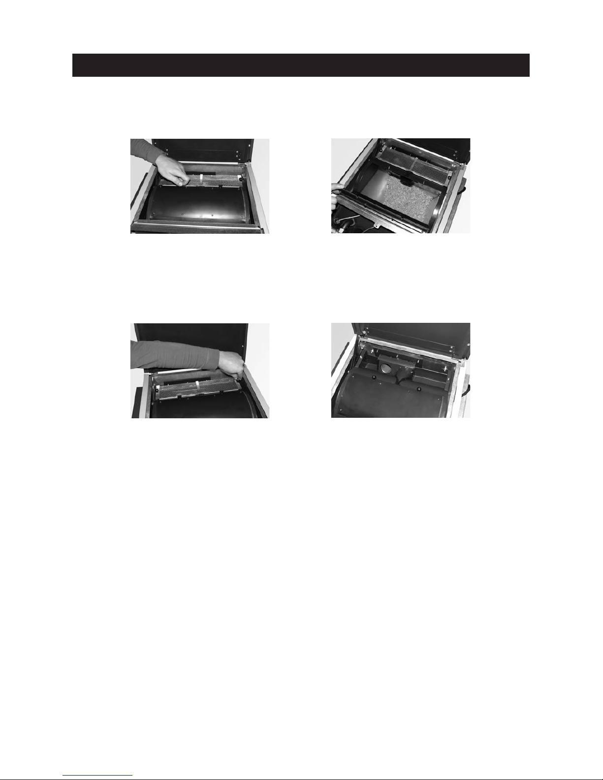
– Remove both knurled screws at the back from the coarse filter (Fig. 139) and remove the coarse filter (Fig.140).
– Remove pellets and dust using a vacuum cleaner.
– Put the coarse filter back on and screw it on with knurled screws.
47
Care, cleaning and maintenance
– Remove both knurled screws (Fig. 137) and fold open the inspection cover (Fig. 138).
– Remove dust (bridge formation) from the container using a vacuum cleaner.
– Close the inspection cover again and screw it on with knurled screws.
Fig. 137 Removing the knurled screws
Fig. 138 Folding open the inspection
cover, removing dust
Fig. 139 Removing the knurled screws
Fig. 140 Removing the coarse filter,
removing pellets and dust
Assembly:
By working through these steps in reverse order.
Page 48
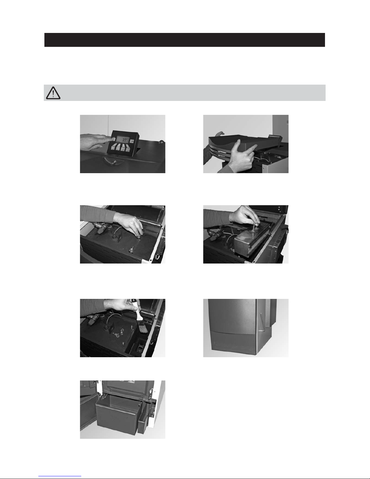
48
3.8 Top heating surfaces and linkage
These parts are automatically checked and cleaned as part of the annual maintenance by WINDHAGER Customer
Service or the customer service PARTNER.
Fig. 142 Removing the cover
Fig. 143 Removing the wing nuts and cover
Fig. 144 Removing the jet protection plate
Care, cleaning and maintenance
Fig. 145 Cleaning top heating surfaces and linkage
Fig. 141 Switching off FireWIN
– Unscrew two wing nuts from the heating surface cover and remove the complete cover – Fig. 143.
– Remove the jet protection plate (tip: vacuum out fly ash first using a vacuum cleaner) – Fig. 144.
Fig. 146 Connecting the lever and operating it several times
Fig. 147 Removing the ash pan(s) or removing the ash
– Empty the ash pan for the heating surfaces (accessory) or remove the ash from the duct – Fig. 147.
– Vacuum off the top heating surfaces and linkage or use a cleaning brush to clean them – Fig. 145.
– Only with FireWIN Klassik and Premium: Push on the cleaning lever of the heating surfaces at the right side
and move it forwards and backwards several times – Fig. 146.
Always switch the boiler off first with the ON/OFF button (Fig. 141) and wait until burnout mode has
finished. It is essential to let the boiler cool down before cleaning.
– Remove the front cover (tip: open the cover of the reserve supply container first) – Fig. 142.
Page 49
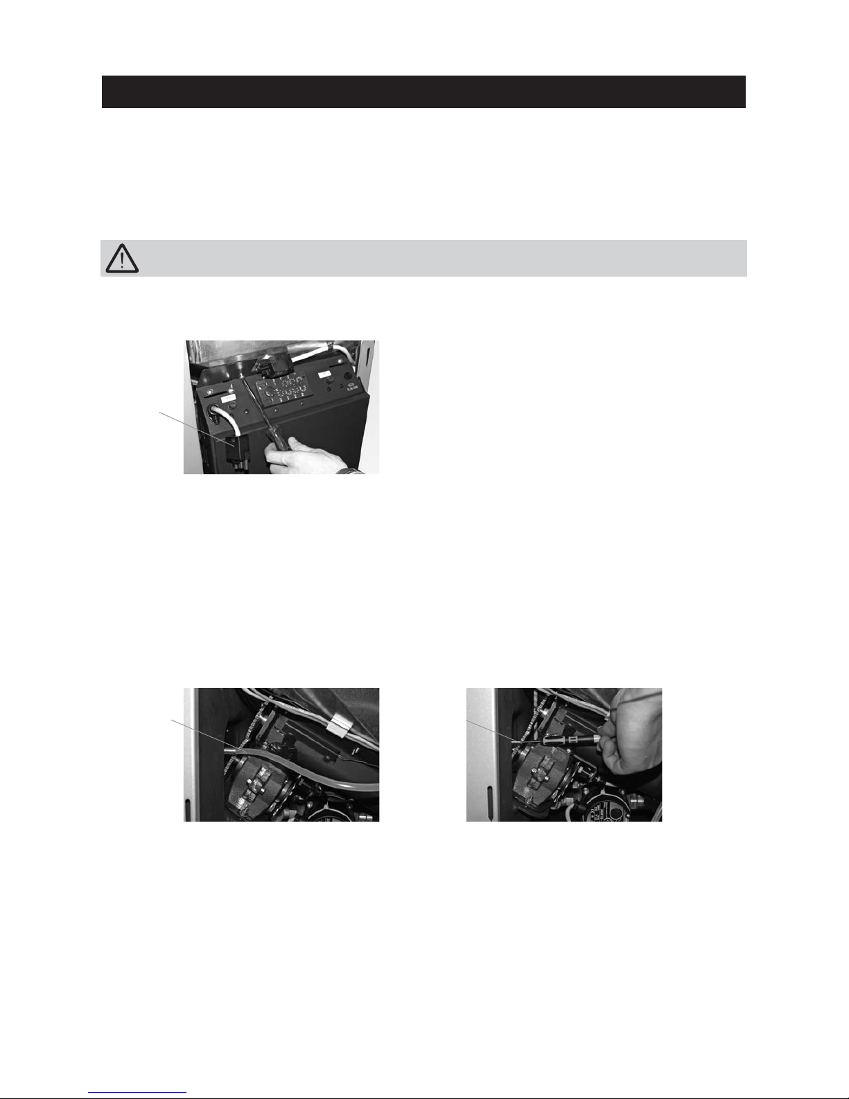
49
3.9.2 Rotary feeder
Cleaning:
– Unscrew the screw plug from the rotary feeder (Fig. 151) and vacuum pellet dust out of the rotary feeder using
a vacuum cleaner.
– Screw the screw plug back in.
Care, cleaning and maintenance
It is essential to let the boiler cool down before cleaning.
– Unhook the right side panel cladding and disconnect the mains power plug over the control panel – Fig. 148
– Remove the screw under the mains power plug on the control panel (Fig. 148) and swivel open the control panel.
3.9.1 Pressure measuring nipple for combustion chamber pressure switch
The pressure measuring nipple must always be free from fly ash so that the combustion chamber pressure can
be monitored.
Cleaning:
– Pull the pressure hose off the pressure measuring nipple (Fig. 149) and clean the induction opening in the pres-
sure measuring nipple, e.g. using a small screwdriver, drill bit or the like – Fig. 150.
– Push the pressure hose back onto the measuring nipple.
These parts are automatically checked and cleaned as part of the annual maintenance by WINDHAGER Customer
Service or the customer service PARTNER.
Fig. 149 Pulling off the pressure hose
Fig. 148 Removing the power plug and screw
Fig. 150 Cleaning the induction opening with
a small screwdriver or the like
3.9 Pressure measuring nipple, rotary feeder, blower wheel,
blower box and exhaust pipe
Pressure hose Pressure meas-
uring nipple
Mains power
plug
Page 50
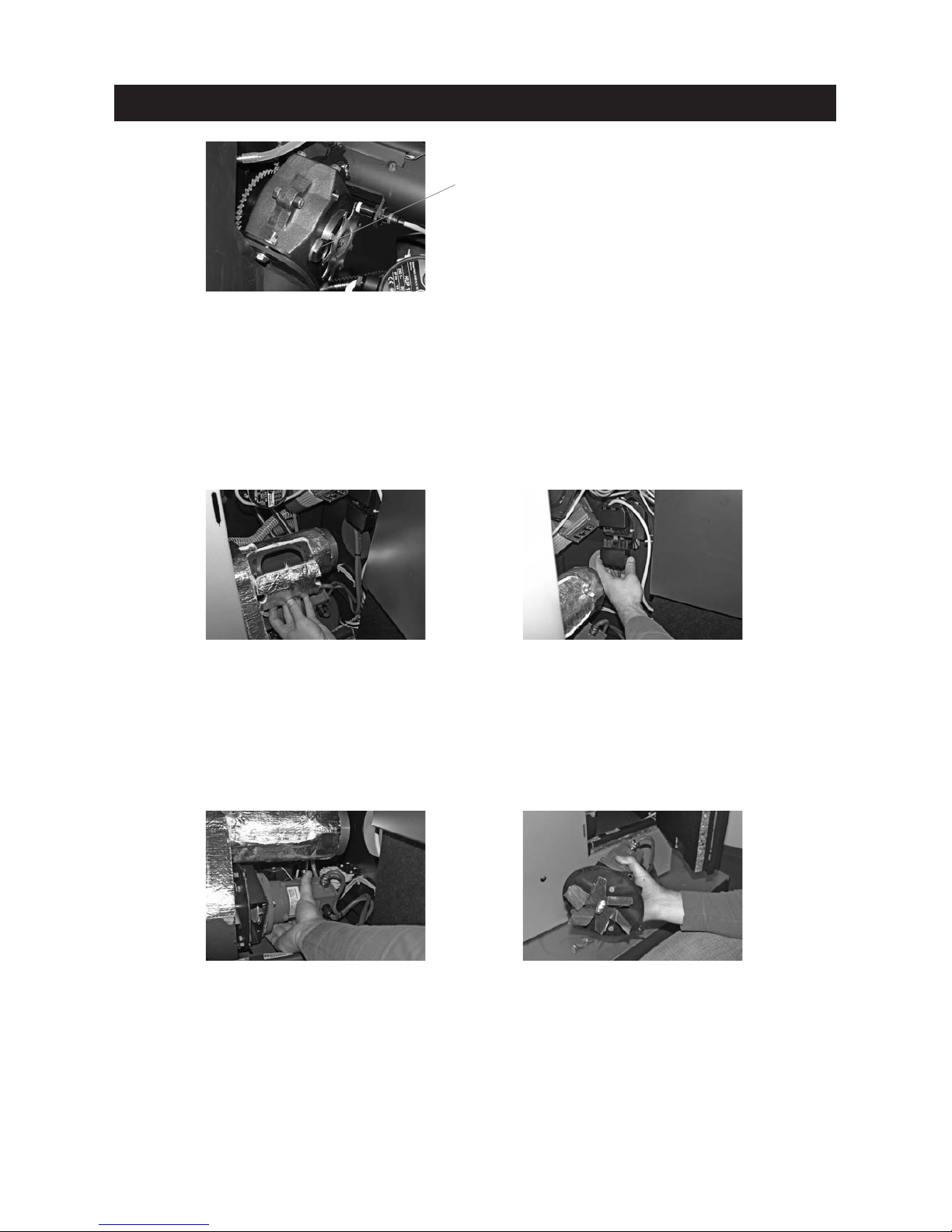
50
Care, cleaning and maintenance
3.9.3 Blower wheel, blower box and exhaust pipe to flue
Fig. 153 Disconnecting the blower
plug
Fig. 152 Removing the wing nuts and cleaning
opening – cleaning the exhaust pipe
– Unscrew two wing nuts from the exhaust pipe and remove the cleaning cover (Fig. 152). Clean fly ash out of the
exhaust pipe with a vacuum cleaner. Close the cleaning cover again.
– Disconnect the blower plug – Fig. 153.
Fig. 155 Cleaning the blower wheel
Fig. 154 Removing wing nuts, removing the
blower unit
Fig. 151 Removing dust from the rotary feeder
– Unscrew two wing nuts from the blower box and remove the complete blower unit – Fig. 154.
– Clean the blower wheel using a spatula and brush – Fig. 155.
– Clean fly ash out of the inside of the blower box with a vacuum cleaner.
Assembly:
– Guide the blower unit in at the back using the staybolts and attach at the front with two wing nuts.
– Reconnect the blower plug.
– Close the control panel, connect the securing mechanism and mains power plug at the top using a screw and
hook in the side panel.
Screw plug
Page 51
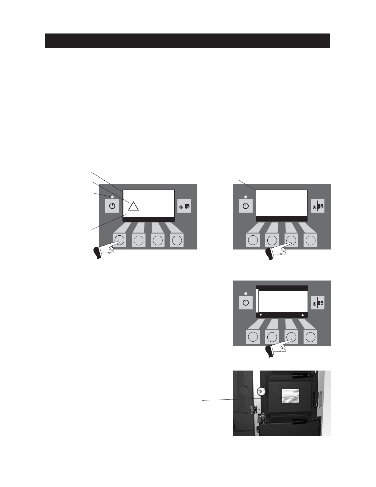
51
5s
RESET5sRESET5sRESET
Troubleshooting
The FireWIN pellet boiler is self-monitoring during operation. All deviations from normal operation are displayed
on the InfoWIN by information, fault or alarm messages. If one of these messages appears, the LED lights up
red, an information, fault or alarm symbol flashes, an information code is displayed along with a brief description in full text – Fig. 155.
Pressing the Info button (Fig. 156) displays the related information text (Fig. 157). To exit the information text
menu, press the Back button (Fig. 157) or wait 10 seconds and the information, fault or alarm message is displayed again – Fig. 156.
With almost all messages, it is necessary to press the Reset button after rectifying the cause of the information, fault or alarm message. In these cases, “Reset” is displayed in the menu line – Fig. 156.
If “Reset” is not displayed in the menu line, the boiler starts operating again automatically after the cause of
the information, fault or alarm message has been rectified.
Pressing the Test button changes to the actuator test immediately. This function is only intended for trained
service personnel (directions for setting, see the FireWIN installation instructions).
Fig. 156
LED “red”
Brief description
Flashing symbol
Information code
Information text
Fig. 157
If you wish to call WINDHAGER Customer Service or your customer
service PARTNER due to a malfunction, please first make a note of
the following data from the rating plate:
- Model
- Factory number
- Year of manufacture
The rating plate is located behind the cladding door between the combustion chamber door and the ash door – Fig. 159.
Rating plate
Fig. 159 Rating plate
Fig. 158
Pressing the Back button (Fig. 158) exits the actuator test.
Vacuum fan
defective
AL 016
Info Reset Test
42
°C
!
Clean blower wheel and
clean blower box.
Press reset.
Follow the operating
instructions.
Back
Vacuum fan
Auger conveyor
Grate shaking
Ignition element
Ash compression
Heating surface cleaning
Choose Back
Page 52
52
Troubleshooting
4.3 Fault messages
4.2 Information messages
Code Meaning/effect Cause/remedy
IN 581
Replenish fuel
Limit switch in the reserve supply container has switched, boiler continues to
heat until the remaining fuel quantity
has been consumed.
The reserve supply container is almost empty.
a) FireWIN Klassik (without feed):
Fill fuel into the fuel container (see section 2.3).
b) FireWIN Premium/Exklusiv (with feed): Feed is switched off in “feed oper-
ating mode” (see section 2.8.1.2). In “Feed operating mode” menu item, set
to “with enable time”, “with start time” or “without time control”.
IN 582
Reserve supply container empty
Reserve supply container is empty,
burner locked
The reserve supply container is empty.
a) FireWIN Klassik without feed:
Fill fuel into the fuel container (see section 2.3).
b) FireWIN Premium/Exklusiv (with feed):
Feed is switched off in “feed operating mode” (see section 2.8.1.2). In “Feed
operating mode” menu item, set to “with enable time”, “with start time”
or “without time control”.
IN 590
Clean boiler and burner
Boiler and burner are still operating.
Boiler and burner must be cleaned (see sections 3.4, 3.5 and 3.6). Following
cleaning, confirm cleaning on the InfoWIN operator level (see section 2.8.1.6).
IN 595
Cladding door open
Cladding door is open, burner locked.
a) Close the cladding door.
b) Door switch on cladding door does not switch correctly, adjust – see instal-
lation instructions.
Code Meaning/effect Cause/remedy
FE 206
Monitoring of the auger conveyor is defective
The boiler is in operation.
Press the Reset button. If the fault reoccurs after a reset, inform Windhager
Customer Service or a heating technician.
FE 238
Feed is not sucking any pellets in
No pellet feed is possible. The boiler
does not operate.
a) No pellets at the suction wand – Set “Wand switching” to “automated” or
select another wand (see section 2.8.1.4). Press the Reset button.
b) Feed hose blocked at the intake or entry to the changeover unit – clear it.
Press the Reset button.
c) Inform Windhager Customer Service or a heating technician.
Emergency operation: Switch off the feed unit (see section 2.8.1.2). Fill the reserve
supply container with pellets by hand, boiler is allowed to continue operating without feed.
Code Meaning/effect Cause/remedy
–
No display
Boiler is off, cannot be switched on with
the ON/OFF button.
a) No electricity, check the cable to the device and the building fuse.
b) No electricity, device fuse blown – check and renew if necessary, see page
55, Fig. 159.
c) InfoWIN plug loose or poorly connected together during installation – check
and connect together firmly if necessary, plug is located on the side at the
top behind the right side panel cladding – see installation instructions;
Installing the cladding.
4.1 No display on InfoWIN
Page 53
53
Troubleshooting
4.4 Alarm messages
Code Meaning/effect Cause/remedy
FE 239
Wand switching defective
No pellet feed is possible. The boiler
does not operate.
Press the Reset button. If the fault reoccurs after a reset, inform Windhager Customer Service or a heating technician.
Emergency operation:Switch off the feed unit (see section 2.8.1.2). Fill the reserve
supply container with pellets by hand, boiler is allowed to continue operating without feed.
FE 356
Combustion chamber pressure
not stable
The boiler is in operation.
a) Heating surface cover leaking, check whether firmly closed (see section
3.8), press the Reset button.
b) Combustion chamber and ash door leaking, check the seal, renew the seal
if necessary, press the Reset button.
c) Pressure measuring nipple of combustion chamber pressure switch is
blocked – clear it (see section 3.9.1), press the Reset button.
d) Intake air line or induction opening at rear is blocked – clear it and press
the Reset button.
e) Exhaust pipe or flue is blocked, clear it and press the Reset button.
f) Combustion chamber pressure switch is defective, inform Windhager Cus-
tomer Service or a heating technician.
FE 381
Reserve supply container empty
Feed is outside the enable time.
Enable time for the feed has been set too short, which means the pellets in
the reserve supply container are used up and the feed is blocked.
Extend the enable time for the feed in the “Feed operating mode” menu item
(see section 2.8.1.3) or operate “with start time” or “without time control” (see
section 2.8.1.2).
FE 382
Fill level switch (proximity
switch) in reserve supply container does not switch
The boiler does not operate.
Fill level switch (proximity switch) in the reserve supply container defective
– inform Windhager Customer Service or a heating technician.
Emergency operation: Switch off the feed unit (see section 2.8.1.2). Fill the reserve
supply container with pellets by hand, boiler is allowed to continue operating without feed.
FE 390
Emergency operation!
Clean boiler and burner
The boiler enters cyclic operation, i.e.
boiler stops during operation.
a) Boiler and burner must be cleaned or the ash pan(s) emptied (see sections
3.4, 3.5 and 3.6). Following cleaning, confirm cleaning on the InfoWIN operator level (see section 2.8.1.6).
b) Motor or limit switch of ash compactor defective, inform Windhager Cus-
tomer Service or a heating technician.
Code Meaning/effect Cause/remedy
AL 005
Grate shaking defective
Shaker motor no longer moves or no
longer reaches the end position, boiler
switches to burnout mode.
a) Grate disc sticking, clean burner pot (see section 3.6), press the Reset button.
b) Shaker motor defective, inform Windhager Customer Service or a heat-
ing technician.
c) Limit switch defective, inform Windhager Customer Service or a heating
technician.
AL 006
Auger conveyor motor defective
Boiler enters burnout mode, vacuum
fan is stopped immediately.
a) Press the Reset button. If the malfunction recurs immediately after a short
period, or recurs at regular intervals, contact Windhager Customer Service or your heating technician.
b) Renew the auger conveyor motor, inform Windhager Customer Service or
a heating technician.
Page 54
54
Troubleshooting
Code Meaning/effect Cause/remedy
AL 016
Vacuum fan defective
The actual speed is different from the nominal speed. The boiler switches to burnout
mode.
a) The blower wheel and blower box are dirty, press the Reset button.
If the malfunction recurs immediately after a short period, or recurs
at regular intervals, contact Windhager Customer Service or your
heating technician.
b) Renew the vacuum fan motor, inform Windhager Customer Service
or a heating technician.
AL 062
Air choke defective (optional)
External air choke does not open.
a) Check the air choke, press the Reset button.
b) Inform Windhager Customer Service or a heating technician.
AL 071
Emergency heating/OFF switch
switched off
Boiler enters burnout mode, however the
blower does not run.
Switch on emergency heating/OFF switch.
AL 076
Boiler sensor defective
The boiler switches to burnout mode.
a) Press the Reset button. If the malfunction recurs immediately after a
short period, or recurs at regular intervals, contact Windhager Customer Service or your heating technician.
b) Renew the boiler sensor, inform Windhager Customer Service or a
heating technician.
AL 078
Temperature sensor defective
The boiler switches to burnout mode.
a) Press the Reset button. If the malfunction recurs immediately after a
short period, or recurs at regular intervals, contact Windhager Customer Service or your heating technician.
b) Renew the temperature sensor, inform Windhager Customer Service
or a heating technician.
AL 128
No flame formation in control mode
The flame goes out in modulation mode. The
boiler switches to burnout mode.
a) Clean the burner and the boiler. Check the exhaust pipe to the flue
and clean it if necessary, press the Reset button.
b) Auger conveyor or rotary feeder jammed due to a foreign body, clean
the reserve supply container (see section 3.7) and remove the foreign
body through the opening above the auger, refill the reserve supply
container. The alarm message AL 171 may light on up to 2 occasions
until the boiler starts operating again, press the Reset button.
c) Inform Windhager Customer Service or a heating technician.
AL 133
Safety thermostat has tripped
Boiler temperature is above 100 °C, boiler
enters burnout mode, vacuum fan is
switched off immediately.
a) Check the water level or pressure in the heating system – re-fill, bleed
the air.
b) Air in the heating system – bleed air.
c) The heat pump or boiler feed pump is sticking or is defective – start
pump manually or have it repaired.
Once the boiler water temperature falls below 90 °C, remove the cover,
press the Release button of the safety thermostat B7 firmly – Fig. 160.
If the malfunction occurs after a short period, or recurs at regular intervals, contact Windhager Customer Service or your heating technician.
AL 135
Excess temperature in the auger tube
The boiler switches to burnout mode.
a) Check the burner, remove all pellets from the burner pot.
b) Remove the cover from the safety thermostat auger tube B7a, press
the Release button firmly (see Fig. 160). If the ignition does not function first time (AL 171), press the Reset button (pellets in the auger
conveyor will have been damaged due to the high temperature).
Page 55
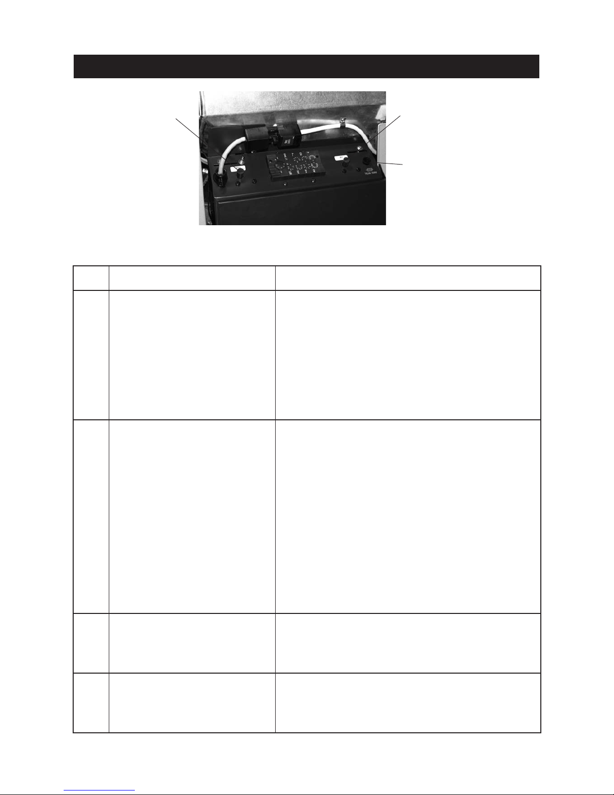
55
Troubleshooting
Code Meaning/effect Cause/remedy
AL 156
No negative pressure in the
combustion chamber
The boiler switches to burnout mode.
a) Heating surface cover leaking, check whether firmly closed (see sec-
tion 3.7), press the reset button.
b) Combustion chamber and ash door leaking, check the seal, renew the
seal if necessary, press the reset button.
c) Pressure measuring nipple of combustion chamber pressure switch is
blocked – clear it (see section 3.9.1), press the reset button.
d) Intake air line or induction opening at rear is blocked – clear it and press
the reset button.
e) Exhaust pipe or flue is blocked, clear it and press the reset button.
f) Combustion chamber pressure switch is defective, inform Windhager
Customer Service or a heating technician.
AL 171
Maximum heating up time exceeded
No flame formation when heating up. Heating-up procedure is cancelled.
a) FireWIN Klassik without feed: The reserve supply container is empty.
Fill fuel into the fuel container (see section 2.3). Press the Reset button until the boiler starts operating again. The alarm message AL 171
may light on up to 2 occasions, press the Reset button.
b) Clean the burner pot (see section 3.6), empty the ash pan in Klas-
sik/Premium, press the reset button.
c) Too much dust in the reserve supply container – bridge formation,
remove the dust (see section 3.6), press the reset button.
d) Auger conveyor or rotary feeder jammed due to a foreign body, clean
the reserve supply container or rotary feeder (see section 3.7) and
remove the foreign body, refill the reserve supply container. The alarm
message AL 171 may light on up to 2 occasions until the boiler starts
operating again, press the Reset button.
e) FireWIN Premium/Exklusiv with feed: Pellets stuck in the hose before
the entry to the reserve supply container – move the hoses at the connection pieces, press the Reset button.
f) Ignition defective, inform Windhager Customer Service or a heating
technician.
AL 187
No communication with
automatic firing device
The boiler switches to burnout mode.
a) Check the connection cable or InfoWIN plug connection to the auto-
matic firing device, inform Windhager Customer Service or a heating
technician.
b) Connect the automatic firing device, inform Windhager Customer Ser-
vice or a heating technician.
AL 188
Internal error occurred
ErrorCode 188
Current TablelD 4
Internal communication error. The boiler
switches to burnout mode.
A reset is performed automatically after 1 minute if this error occurs.
If the malfunction occurs after a short period, or recurs at regular intervals, contact Windhager Customer Service or your heating technician.
Fig. 160 FireWIN control panel, rear right side panel removed
Cover of safety thermostat B7
Cover of safety thermostat
auger tube B7a
Device fuse T 6.3 A
Page 56
56
The guarantee and warranty limitations require that the boiler and related accessories be properly installed and
started up by WINDHAGER Customer Service or Customer Service PARTNER; otherwise the manufacturer’s guarantee will not be honoured.
Malfunctions resulting from improper operation or adjustment as well as use of poor or not recommended fuel
types are not covered by the guarantee and warranty. Further, the warranty shall be void if equipment other
than those provided by WINDHAGER are installed. The special warranty restrictions for your system are available in the “Warranty Conditions” folder supplied with your boiler.
Guarantee and warranty limitations
Start-up and regular maintenance following the terms of the “Warranty Conditions” will assure safe,
environmentally friendly and economical operation of your system. We recommend that you obtain a
maintenance service contract.
Subject to technical modifications. AWÖ-vor-11/2005 überstetzt von 023743/02
Contacts
Regional customer service
Salzburg: Upper Austria: Tyrol, Vorarlberg: Carinthia:
Tel. +43 (0) 62 12/23 41-267 Tel. +43 (0) 62 12/23 41-266 Tel. +43 (0) 6212/23 41-263 Tel. +43 (0) 6212/23 41-269
Fax +43 (0) 62 12/45 04 Fax +43 (0) 62 12/45 04 Fax +43 (0) 6212/45 04 Fax +43 (0) 62 12/45 04
Vienna, Lower Austria, Burgenland: Styria:
Tel. +43 (0) 1/869 43 28-340 or 01/869 43 28-450 Tel. +43 (0) 1/869 43 28-670
Fax +43 (0) 1/865 13 81 Fax +43 (0) 1/865 13 81
E-mail: [email protected]
Technical assistance:
Tel: +43(0) 6212/23 41-264
Fax +43 (0) 62 12/23 41-259
Headquarters:
Windhager Zentralheizung GmbH
A-5201 Seekirchen
Anton-Windhager-Str. 20
Tel. +43 (0)62 12/2341-0
Fax +43 (0) 62 12/42 28
E-mail: [email protected]
Spare parts:
Tel. +43(0) 6212/23 41-268
Fax +43 (0) 62 12/42 26
Windhager Zentralheizung GmbH
D-86405 Meitingen
Deutzring 2
Tel. +49(0) 8271/80 56-0
Fax +49 (0) 82 71/80 56-30
E-mail: [email protected]
Customer service, western and southern Germany:
Tel. +49(0) 8271/80 56-0
E-mail: [email protected]
Windhager Zentralheizung Schweiz AG
CH-6203 Sempach-Station
Industriestraße 13
Tel. +41(0) 41/4694 69-0
Fax +41 (0) 41/46 94 69-9
Spare parts: +41 (0) 41/46 94 69-0
E-mail: [email protected]
Regional customer service
for German-speaking Switzerland:
Tel. +41(0) 41/4694 69-6
E-mail: [email protected]
Windhager Zentralheizung GmbH
D-04509 Delitzsch
Heinrich-Rudolf-Hertz-Str. 2
Tel. +49(0) 342 02/723-0
Fax +49 (0) 3 42 02/7 23-30
E-mail: [email protected]
Customer service, northern and eastern Germany:
Tel. +49(0) 342 02/723-0
E-mail: [email protected]
Switzerland:
Germany:
Austria:
 Loading...