

Windhager DuoWIN Assembly Instructions
WOOD / PELLETS
Assembly instructions
DuoWIN
with Hybrid Technology
Combined Heating with Wood and Pellets
For Single and Multiple Family Homes
Output Range: 4,3 to 30 kW
12/2014 094836/00

2
Table of contents
Table of contents
1. Important Initial Information for the Technician . . . . . . . . . . . . . . . . . . . . . . . . . . . . . . . . . . .4
1.1 Safety precautions . . . . . . . . . . . . . . . . . . . . . . . . . . . . . . . . . . . . . . . . . . . . . . . . . . . . . . . . . . . . . . . . . . . . . .4
1.2 Flue . . . . . . . . . . . . . . . . . . . . . . . . . . . . . . . . . . . . . . . . . . . . . . . . . . . . . . . . . . . . . . . . . . . . . . . . . . . . . . . . . .4
1.3 Boiler room/installation room . . . . . . . . . . . . . . . . . . . . . . . . . . . . . . . . . . . . . . . . . . . . . . . . . . . . . . . . . . . . 5
1.4 Initial commissioning and operating instructions . . . . . . . . . . . . . . . . . . . . . . . . . . . . . . . . . . . . . . . . . . . . .5
1.4 Fuel storage . . . . . . . . . . . . . . . . . . . . . . . . . . . . . . . . . . . . . . . . . . . . . . . . . . . . . . . . . . . . . . . . . . . . . . . . . . .6
2. For the Installer . . . . . . . . . . . . . . . . . . . . . . . . . . . . . . . . . . . . . . . . . . . . . . . . . . . . . . . . . . . . . 8
2.1 Delivery, packaging . . . . . . . . . . . . . . . . . . . . . . . . . . . . . . . . . . . . . . . . . . . . . . . . . . . . . . . . . . . . . . . . . . . . .8
2.2 System . . . . . . . . . . . . . . . . . . . . . . . . . . . . . . . . . . . . . . . . . . . . . . . . . . . . . . . . . . . . . . . . . . . . . . . . . . . . . . . .9
2.2.1 Area of use . . . . . . . . . . . . . . . . . . . . . . . . . . . . . . . . . . . . . . . . . . . . . . . . . . . . . . . . . . . . . . . . . . . . . . . . . . . . . . . . 9
2.2.2 Standards . . . . . . . . . . . . . . . . . . . . . . . . . . . . . . . . . . . . . . . . . . . . . . . . . . . . . . . . . . . . . . . . . . . . . . . . . . . . . . . . . 9
2.2.3 Heating circuits . . . . . . . . . . . . . . . . . . . . . . . . . . . . . . . . . . . . . . . . . . . . . . . . . . . . . . . . . . . . . . . . . . . . . . . . . . . . 9
2.2.4 Circulation pump . . . . . . . . . . . . . . . . . . . . . . . . . . . . . . . . . . . . . . . . . . . . . . . . . . . . . . . . . . . . . . . . . . . . . . . . . . 10
2.2.5 Return temperature . . . . . . . . . . . . . . . . . . . . . . . . . . . . . . . . . . . . . . . . . . . . . . . . . . . . . . . . . . . . . . . . . . . . . . . 10
2.2.6 Accumulator tank . . . . . . . . . . . . . . . . . . . . . . . . . . . . . . . . . . . . . . . . . . . . . . . . . . . . . . . . . . . . . . . . . . . . . . . . . 10
2.2.7 Operating with external control . . . . . . . . . . . . . . . . . . . . . . . . . . . . . . . . . . . . . . . . . . . . . . . . . . . . . . . . . . . . . . 11
2.2.8 Domestic water - wood gasification boiler (hot water tank heating in summer) . . . . . . . . . . . . . . . . . . . . . . . 11
2.2.9 Heating water . . . . . . . . . . . . . . . . . . . . . . . . . . . . . . . . . . . . . . . . . . . . . . . . . . . . . . . . . . . . . . . . . . . . . . . . . . . . 11
2.2.10 Water-side resistance (pressure loss) . . . . . . . . . . . . . . . . . . . . . . . . . . . . . . . . . . . . . . . . . . . . . . . . . . . . . . . . . 12
2.3 Combustion air . . . . . . . . . . . . . . . . . . . . . . . . . . . . . . . . . . . . . . . . . . . . . . . . . . . . . . . . . . . . . . . . . . . . . . . . 13
2.4 Installation sequence . . . . . . . . . . . . . . . . . . . . . . . . . . . . . . . . . . . . . . . . . . . . . . . . . . . . . . . . . . . . . . . . . . .14
2.4.1 Minimum service clearances for fire protection, cleaning, and maintenance . . . . . . . . . . . . . . . . . . . . . . . . . 14
2.4.2 Transport to installation site . . . . . . . . . . . . . . . . . . . . . . . . . . . . . . . . . . . . . . . . . . . . . . . . . . . . . . . . . . . . . . . . . 16
2.4.3 Installation parts . . . . . . . . . . . . . . . . . . . . . . . . . . . . . . . . . . . . . . . . . . . . . . . . . . . . . . . . . . . . . . . . . . . . . . . . . . 18
2.4.4 Note before installation . . . . . . . . . . . . . . . . . . . . . . . . . . . . . . . . . . . . . . . . . . . . . . . . . . . . . . . . . . . . . . . . . . . . . 21
2.4.5 Wood gasification boiler: Installing the flue connection adapter . . . . . . . . . . . . . . . . . . . . . . . . . . . . . . . . . . . . 21
2.4.6 Wood gasification boiler: Mount the set screws, set door catch . . . . . . . . . . . . . . . . . . . . . . . . . . . . . . . . . . . . 23
2.4.7 Wood gasification boiler: Installing the flue gas blower, air control, and lambda sensor . . . . . . . . . . . . . . . . 24
2.4.8 Wood gasification boiler: lighting door with automatic ignition installation . . . . . . . . . . . . . . . . . . . . . . . . . . . 24
2.4.9 Wood gasification boiler: carburisation gas duct installation . . . . . . . . . . . . . . . . . . . . . . . . . . . . . . . . . . . . . . 25
2.4.10 Wood gasification boiler: Mount shaft for heating surface cleaning lever . . . . . . . . . . . . . . . . . . . . . . . . . . . . 26
2.4.11 Wood gasification boiler: insulation installation . . . . . . . . . . . . . . . . . . . . . . . . . . . . . . . . . . . . . . . . . . . . . . . . . 27
2.4.12 Wood gasification boiler: side panels installation . . . . . . . . . . . . . . . . . . . . . . . . . . . . . . . . . . . . . . . . . . . . . . . . 28
2.4.13 Wood gasification boiler: control panel installation . . . . . . . . . . . . . . . . . . . . . . . . . . . . . . . . . . . . . . . . . . . . . . 29
2.4.14 Wood gasification boiler: thermocontrol sensor installation . . . . . . . . . . . . . . . . . . . . . . . . . . . . . . . . . . . . . . . 30
2.4.15 Wood gasification boiler: thermocontrol sensor cover installation . . . . . . . . . . . . . . . . . . . . . . . . . . . . . . . . . . . . 30
2.4.16 Wood gasification boiler: mains connection and sensor installation . . . . . . . . . . . . . . . . . . . . . . . . . . . . . . . . . . . 31
2.4.17 Wood gasification boiler: rear panel insulation installation . . . . . . . . . . . . . . . . . . . . . . . . . . . . . . . . . . . . . . . . 33
2.4.18 Wood gasification boiler: rear panels installation . . . . . . . . . . . . . . . . . . . . . . . . . . . . . . . . . . . . . . . . . . . . . . . . 33
2.4.19 Wood gasification boiler: Installation of blower housing on the adapter . . . . . . . . . . . . . . . . . . . . . . . . . . . . . 34
2.4.20 Wood gasification boiler: cleaning heating surfaces lever installation . . . . . . . . . . . . . . . . . . . . . . . . . . . . . . . . . . . 35
2.4.21 Wood gasification boiler: control panel installation . . . . . . . . . . . . . . . . . . . . . . . . . . . . . . . . . . . . . . . . . . . . . . 36
2.4.22 Wood gasification boiler: cladding door installation . . . . . . . . . . . . . . . . . . . . . . . . . . . . . . . . . . . . . . . . . . . . . . 37
2.4.23 Wood gasification boiler: cladding adjustment . . . . . . . . . . . . . . . . . . . . . . . . . . . . . . . . . . . . . . . . . . . . . . . . . . 38
2.4.24 Wood gasification boiler: checking the cladding door switch . . . . . . . . . . . . . . . . . . . . . . . . . . . . . . . . . . . . . . 38
2.4.25 Wood gasification boiler: mounting the front boiler cover . . . . . . . . . . . . . . . . . . . . . . . . . . . . . . . . . . . . . . . . . 39
2.4.26 Wood gasification boiler: mounting the rear boiler cover . . . . . . . . . . . . . . . . . . . . . . . . . . . . . . . . . . . . . . . . . . 39
2.4.27 Wood gasification boiler: Punch out the side panel . . . . . . . . . . . . . . . . . . . . . . . . . . . . . . . . . . . . . . . . . . . . . . 40

3
Table of contents
2.4.28 Wood gasification boiler: Mount the positioning bracket . . . . . . . . . . . . . . . . . . . . . . . . . . . . . . . . . . . . . . . . . . 40
2.4.29 Pellet boiler: Assembling the hydraulic piping, part 1 (accessory: DUO 001) . . . . . . . . . . . . . . . . . . . . . . . . . . 41
2.4.30 Pellet boiler: filling and evacuation cock installation . . . . . . . . . . . . . . . . . . . . . . . . . . . . . . . . . . . . . . . . . . . . . 42
2.4.31 Pellet boiler: Integral fuel hopper installation . . . . . . . . . . . . . . . . . . . . . . . . . . . . . . . . . . . . . . . . . . . . . . . . . . 43
2.4.32 Align the pellet boiler to the wood gasification boiler . . . . . . . . . . . . . . . . . . . . . . . . . . . . . . . . . . . . . . . . . . . . 46
2.4.33 Pellet boiler: Integral fuel hopper cladding . . . . . . . . . . . . . . . . . . . . . . . . . . . . . . . . . . . . . . . . . . . . . . . . . . . . . 48
2.4.34 Pellet boiler: Mount cladding front . . . . . . . . . . . . . . . . . . . . . . . . . . . . . . . . . . . . . . . . . . . . . . . . . . . . . . . . . . . 50
2.4.35 Pellet boiler: Mount the cover on the integral fuel hopper side. . . . . . . . . . . . . . . . . . . . . . . . . . . . . . . . . . . . . 51
2.4.36 Pellet boiler: Laying the LON cable . . . . . . . . . . . . . . . . . . . . . . . . . . . . . . . . . . . . . . . . . . . . . . . . . . . . . . . . . . . 52
2.4.37 Pellet boiler: Mount the control panel cover . . . . . . . . . . . . . . . . . . . . . . . . . . . . . . . . . . . . . . . . . . . . . . . . . . . . 53
2.4.38 Pellet boiler: Mount the cover on the pellet boiler side . . . . . . . . . . . . . . . . . . . . . . . . . . . . . . . . . . . . . . . . . . . 53
2.4.39 Pellet boiler: Mounting the cladding door . . . . . . . . . . . . . . . . . . . . . . . . . . . . . . . . . . . . . . . . . . . . . . . . . . . . . . 53
2.4.40 Pellet boiler: Mount integral fuel hopper cover (only for pellet boilers with fully automatic feed) . . . . . . . . . 54
2.4.41 Pellet boiler: Feed and return line assembly (only for pellet boilers with fully automatic feed) . . . . . . . . . . . 54
2.4.42 Cleaning and operating implements . . . . . . . . . . . . . . . . . . . . . . . . . . . . . . . . . . . . . . . . . . . . . . . . . . . . . . . . . . 55
2.4.43 Installation of flue gas connection through cover on integral fuel hopper side . . . . . . . . . . . . . . . . . . . . . . . . 56
2.4.44 Installing the thermal process safeguard . . . . . . . . . . . . . . . . . . . . . . . . . . . . . . . . . . . . . . . . . . . . . . . . . . . . . . 57
2.4.45 Assembling the hydraulic piping, part 2 (accessory: DUO 001) . . . . . . . . . . . . . . . . . . . . . . . . . . . . . . . . . . . . . 57
3. For the Electrician . . . . . . . . . . . . . . . . . . . . . . . . . . . . . . . . . . . . . . . . . . . . . . . . . . . . . . . . . . .58
3.1 Electrical connections . . . . . . . . . . . . . . . . . . . . . . . . . . . . . . . . . . . . . . . . . . . . . . . . . . . . . . . . . . . . . . . . . . 58
3.1.1 Pelletboiler . . . . . . . . . . . . . . . . . . . . . . . . . . . . . . . . . . . . . . . . . . . . . . . . . . . . . . . . . . . . . . . . . . . . . . . . . . . . . . . 58
3.1.2 Wood gasification boiler . . . . . . . . . . . . . . . . . . . . . . . . . . . . . . . . . . . . . . . . . . . . . . . . . . . . . . . . . . . . . . . . . . . . 61
4. For the Service Technician . . . . . . . . . . . . . . . . . . . . . . . . . . . . . . . . . . . . . . . . . . . . . . . . . . . . 64
4.1 Start-up and operating instructions . . . . . . . . . . . . . . . . . . . . . . . . . . . . . . . . . . . . . . . . . . . . . . . . . . . . . . .64
4.2 Service and repair work . . . . . . . . . . . . . . . . . . . . . . . . . . . . . . . . . . . . . . . . . . . . . . . . . . . . . . . . . . . . . . . . .64
4.3 Checking and servicing the thermal process safeguard . . . . . . . . . . . . . . . . . . . . . . . . . . . . . . . . . . . . . . 64
5. Technical Data . . . . . . . . . . . . . . . . . . . . . . . . . . . . . . . . . . . . . . . . . . . . . . . . . . . . . . . . . . . . . . 65
5.1 Technical data for flue gas system calculations acc. to EN 13384-1 . . . . . . . . . . . . . . . . . . . . . . . . . . . . .65
5.2 Require flue cross-sections for the DuoWIN
All specifications are guidelines only and should not take the place of an actual flue calculation! . . .66
5.3 Technical data – General (Wood gasification boiler) . . . . . . . . . . . . . . . . . . . . . . . . . . . . . . . . . . . . . . . . . .67
5.4 Technical data – General (Pellet boiler) . . . . . . . . . . . . . . . . . . . . . . . . . . . . . . . . . . . . . . . . . . . . . . . . . . . . 68
6. Electrical Connection Diagrams . . . . . . . . . . . . . . . . . . . . . . . . . . . . . . . . . . . . . . . . . . . . . . . 70
6.1 Pellet boiler basic circuitry with automatic pellet feed . . . . . . . . . . . . . . . . . . . . . . . . . . . . . . . . . . . . . . . 70
6.2 Pellet boiler basic circuitry with manual pellet feed . . . . . . . . . . . . . . . . . . . . . . . . . . . . . . . . . . . . . . . . .71
6.3 Wood gasification boiler basic circuitry . . . . . . . . . . . . . . . . . . . . . . . . . . . . . . . . . . . . . . . . . . . . . . . . . . . .72
6.4 Pellet boiler connection diagram changeover unit . . . . . . . . . . . . . . . . . . . . . . . . . . . . . . . . . . . . . . . . . . .73
6.5 Pellet boiler pellet feed connection diagram with mixer for buried tank . . . . . . . . . . . . . . . . . . . . . . . .74
6.6 Circuit diagram for pellet boiler pellet feed with 1-probe suction solution . . . . . . . . . . . . . . . . . . . . . . .74
6.7 Connection diagram for air intake flap . . . . . . . . . . . . . . . . . . . . . . . . . . . . . . . . . . . . . . . . . . . . . . . . . . . . .75
Warranty . . . . . . . . . . . . . . . . . . . . . . . . . . . . . . . . . . . . . . . . . . . . . . . . . . . . . . . . . . . . . . . . . . . . . 76
4
1. Important Initial Information for the Technician
1. Important Initial Information for the Technician
The DuoWIN hybrid boiler constitutes the LogWIN Klassik pellet ready wood gasification boiler and the BioWIN 2
pellet boiler with a shared InfoWINPLUS display and operating unit.
1.1 Safety precautions
This boiler and related accessories are state of the art and meet all applicable safety regulations. This boiler
and all accessories operate using 230 V AC electrical current. Improper installation or repair can result in a lifethreatening electric shock. Installation may only be performed by appropriately qualified technicians.
Caution symbols
Please take careful note of the following symbols in this installation manual and on the boiler.
Attention!
Ignoring the warnings identified can lead to personal injury.
Information!
Ignoring the warnings identified can lead to malfunction of, or damage to the boiler or heating system.
Note!
The blocks of highlighted text provide information and tips for operation.
1.2 Flue
A properly dimensioned flue is required for optimal functioning of the combustion system. Measurement of the
dimensions must follow EN 13384-1. See the technical data section for the values required for this calculation.
Please note that in the lower performance range, flue gases may be below 90°C. Hearths should therefore be
connected to thermally insulated flues meeting thermal transmittance coefficient Group I requirements according
to DIN 18160 T1 or other appropriate, officially approved moisture-resistant exhaust systems.
The flue gas system must display at least the following classification:
Temperature class: T400 = nominal operating temperature 400 °C
Soot fire resistance class: G = flue gas system with soot fire resistance
Corrosion resistance class: 2 = suitable for unprocessed wood fuels
We recom
mend fitting an energy-saving intake regulator for problem-free operation. This will largely prevent
moisture in the flue, and losses resulting from down-time will be reduced (draught interruptions). If you have a
feed pressure (flue draught) of more than 0.20 mbar, the energy-saving intake regulator must be fitted.
According to TRVB H118, a deflagration flap (combi energy-saving intake regulator with explosion flap EEX) must
be fitted in the connecting piece (exhaust pipe) or in the flue inside the boiler room.
Please observe the following sections:
2.4.1 Minimum service clearances for fire protection, cleaning, and maintenance
2.4.43 Exhaust pipe installation
Information!
Frequently, overhauling existing systems involves over-sized flue cross-sections or flues not
designed for low-temperature operation. We recommend an evaluation by the local building
inspector before installing the boiler system. In this way, appropriate modifications can be made to
the flue before system installation (see technical data for flue calculation values).

5
1. Important Initial Information for the Technician
1.3 Boiler room/installation room
– Comply with the minimum clearances for connections, cleaning, and maintenance – see section 2.4.1 „Mini-
mum service clearances.“
– There must be sufficient ventilation into the boiler room for the safe operation of the appliance - see section
2.3 „Combustion air.“
– The boiler must only be installed in a dry, frost-free location!
– The boiler may not be installed in very dusty or humid rooms.
Permissible limit values: Air humidity: 85 % at room temperature of 25 °C (non-condensing)
Room temperature: +2 to +40 °C
– Sufficient lighting must be provided for service and maintenance.
Attention!
The configuration of the entire system must comply with technical fire protection requirements in
accordance with the applicable regulations, standards, and guidelines.
1.4 Initial commissioning and operating instructions
Windhager Customer Service or one of our customer service partners must commission the new boiler. They will
familiarize the customer with the boiler system operation and cleaning, with reference to the operation manual.
The following preconditions must be met before ordering the boiler commissioning:
1.) Boiler installed correctly.
2.) System fully electrically wired.
3.) System rinsed, filled, and vented – heat demand must be present.
4.) Boiler connected to domestic water and filled.
5.) Sufficient quantity of fuel available (pellets, split logs, oil, or gas).
6.) The customer must be present during commissioning.
The commissioning cannot be carried out if any of these items are incomplete or neglected. The customer will
be charged for any unnecessary costs arising as a result.
Commissioning and maintenance by Windhager Customer Service or a customer service partner are part of the
guarantee requirements of the enclosed “guarantee limitations.”
Note!
Wood gasification boiler: When the boiler is heated up for the first time, unpleasant smells may
occur from gas emissions due insulation or paint residue being burnt off. Therefore, ensure that the
boiler room/installation room is well vented. Condensation may also form near the coasting surfaces, and the combustion chamber temperature may only increase after a delay.
Note!
Pellet boiler: During the first few weeks after start-up, condensation can occur in the combustion
chamber, ash chamber, and on the heating surfaces. This has no effect on the boiler‘s function and
service life.
6
1. Important Initial Information for the Technician
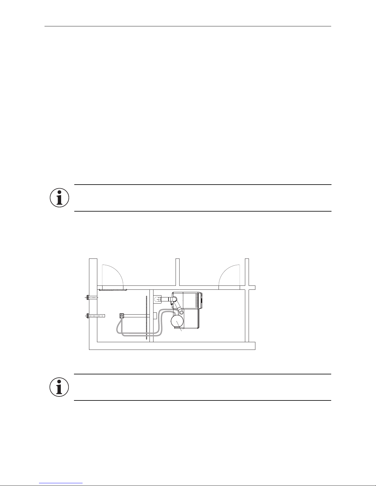
Fig. 2 Storage room, boiler room – view from above
Storage room
Suction turbine
DuoWIN
Boiler room
1 probe:
Information!
For storage rooms smaller than 2 m² without a sloping floor, or for storage rooms between 2 and 4 m²
with a sloping floor.
1.4 Fuel storage
The pellets must be stored in a dry location in order to achieve trouble-free operation with optimum combustion
at maximum efficiency. The pellets can be stored in bulk in a storage room, sheet steel tank, fabric tank or buried
tank. The requirements for pellet storage are defined in ÖNORM M7137 for Austria or the Firing Ordinance (FeuV)
for German
y.
See the separate planning documents for planning information about pellet storage.
DuoWIN with fully automatic pellet feed system
Maximum transport length or height for a pellet feed system:
To achieve the following maximum values will require a stable electrical supply of 220V (under load!)
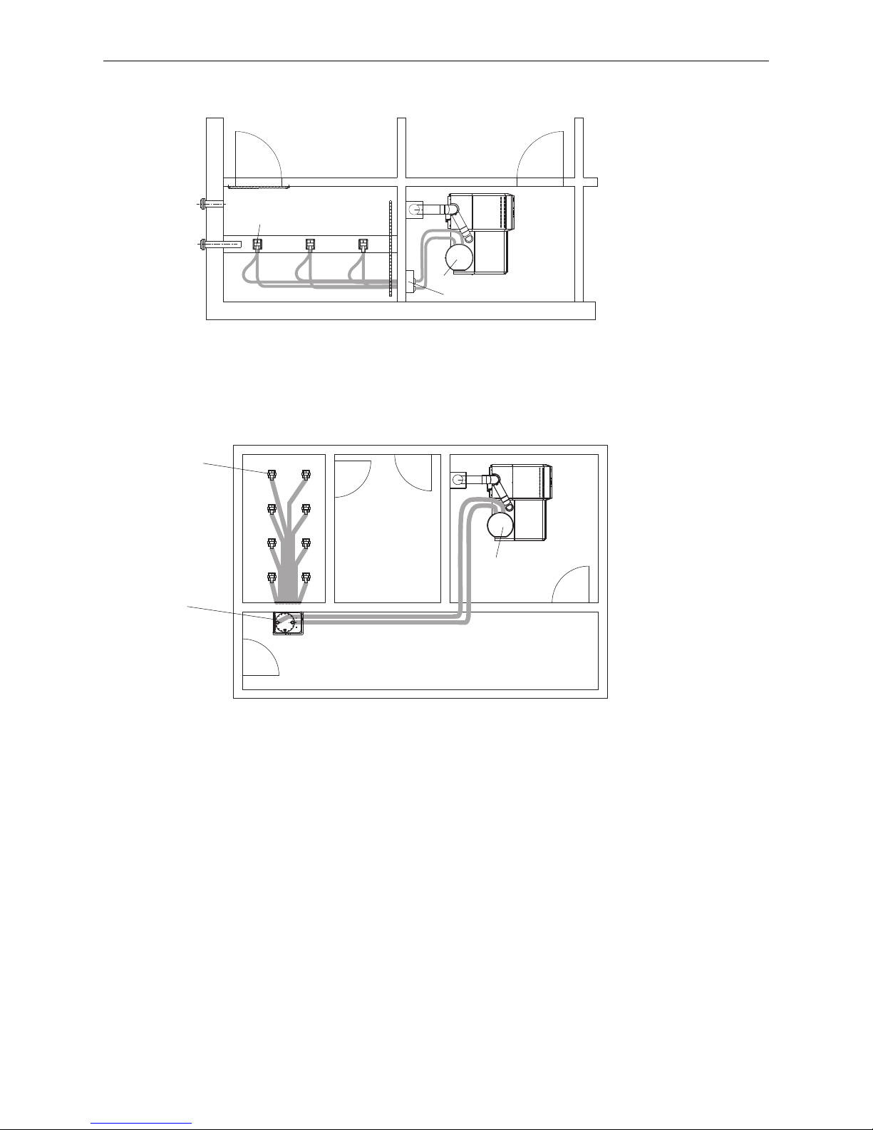
The pellet boiler can be operated with 1 probe (Fig. 2), 2–3 probes (Fig. 3) or with up to 8 probes (Fig. 4).
Max. distance of 25 m between furthest probe and pellet boiler with max. total height difference of 1.8 m.
Max. distance of 15 m between furthest probe and pellet boiler with max. total height difference of 2.8 m.
Max. distance of 10 m between furthest probe and pellet boiler with max. total height difference of 4.5 m.
Total height difference: sum of lengths of all rising pipes
Information!
The pellets must be transported carefully in and out of the storage room in order to maintain good
pellet quality.
7
1. Important Initial Information for the Technician
Fig. 3 Storage room, boiler room – view from above
Fig. 4 Storage room, boiler room – view from above
Furthest away probe
Changeover unit
Storage room
Suction turbine
DuoWIN
Boiler room
Furthest away probe
Changeover unit
Storage room
Suction turbine
DuoWIN
Boiler room
3 probes:
8 probes:
8
2. For the Installer
2. For the Installer
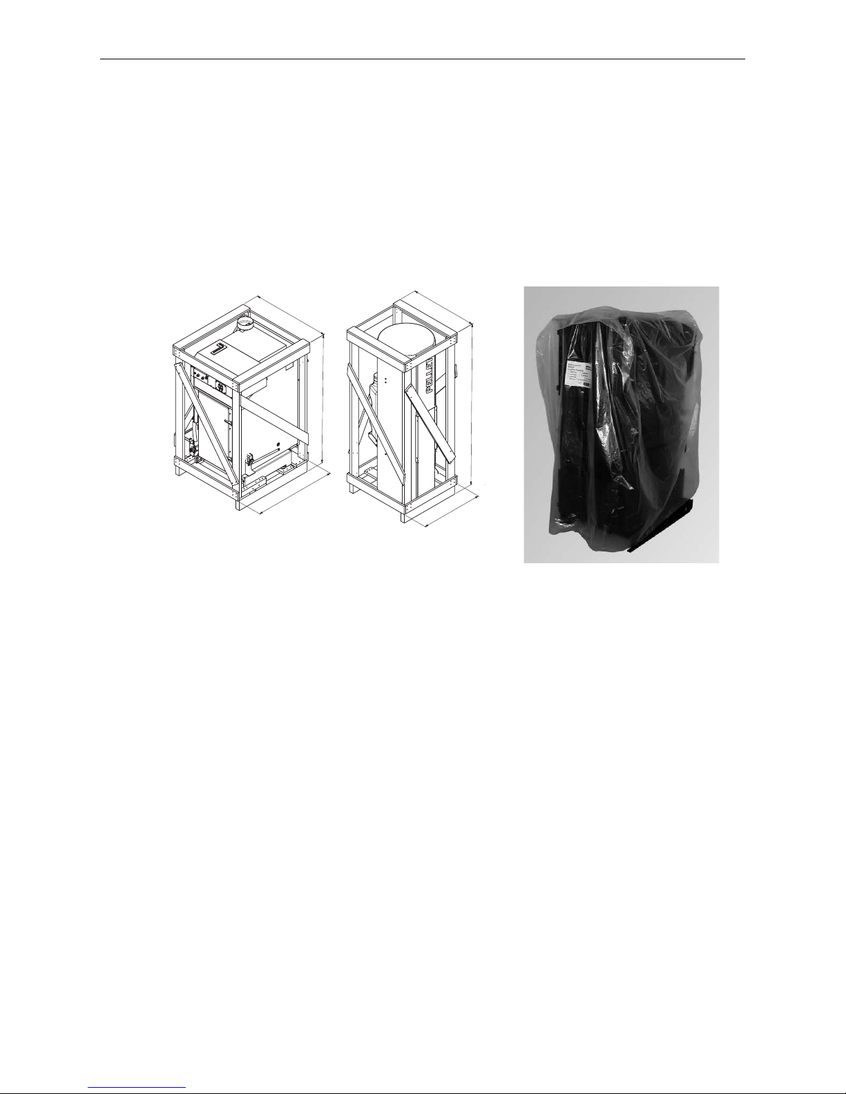
2.1 Delivery, packaging
The wood gasification boiler is delivered covered with a plastic sack. The pellet boiler and the integral fuel
hopper are covered with a plastic sack and packed inside a stable crate. The cladding and installation parts are in
separate cardboard boxes. The cleaning devices are packed inside the filling chamber of the pellet boiler or wood
gasification boiler.
See price list for diverse boiler and storage room accessories.
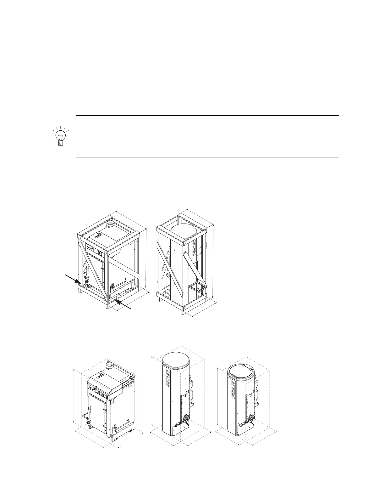
Fig. 5 Scope of delivery
612
812
1161
660
767
6821
1 2

9
2. For the Installer
2.2 System
2.2.1 Area of use
For heating buildings acc. to EN 12831.
These boilers/heaters are designed and approved as heat generators for hot water heating systems with permissible
flow temperatures of up to 90 °C. They may be installed only in sealed systems. The resulting flow temperature
depends on the relevant operating status and the line losses to the system.
Wood gasification boiler:
The max. boiler temperature for the wood gasification boiler is factory-set at 80 °C.
Pellet boiler:
The maximum flow temperature is factory-set at 75°C. In the service level, the max. boiler temperature can be
increased to 85 °C. To do this, an accumulator tank must be installed, which is loaded by the BioWIN 2.
2.2.2 Standards
European standard EN 12828 should be followed. This specifies that the following should be fitted:
a) A closed expansion tank.
b) A reliably functioning safety valve installed at the highest point of the boiler or at a non-closable line.
c) A thermometer and pressure gauge.
d) A low-water cut-off: this not required for systems providing up to 300 kW nominal thermal output, if it can be
assured that excess heating will not result from a lack of water in the system.
If the boiler is above the radiators, then a low-water cut-off must be installed.
e) Wood gasification boiler: an automatic device for dissipating heat, which will prevent the maximum boiler
water temperature from exceeding 110°C. The built-in thermal safety device (heat exchanger) should always
be used with the thermal discharge safeguard (accessory FK-060).
2.2.3 Heating circuits
Several heating circuits:
In-line regulating valves should be installed to permit better regulation of the system. In an uninsulated building
(new building, not yet plastered), the calculated and actual heating requirements often differ considerably.
Minimum heat consumption:
The smallest possible boiler power must continuously be dissipated from the boiler during operation. Suitable
measures to ensure minimum heat consumption should be maintained throughout the entire burning time, e.g.:
– Correctly dimensioned buffer tank - see2.2.6.
– Function of the MESplus controller in the WVF+ function module on the master user module, including no
thermostatic valves.
– Non-blockable heating circuit never fully closed, including no thermostatic valves.
Note!
Elevated room temperatures may sporadically occur if operating with the MESplus function.
Motorised mixing valve:
A motorised mixing valve is always required for each heating circuit. A feed contact thermostat (FK-001) must be
installed for underfloor circuits.
10
2. For the Installer
Boiler start-up relief for wood gasification boiler:
Basically, a boiler startup relief always has to be installed for the wood gasification boiler so that the circulation
pump(s) switch off at boiler temperatures below 62°C. This prevents condensation from forming in the boiler and
extends its service life. A similar boiler start-up relief is contained in the MESplus control system.
2.2.4 Circulation pump
Since 2013, new circulation pumps are required in Europe to fulfill minimum energy efficiency requirements.
Please refer to the Energy Efficiency Index (EEI).
2.2.5 Return temperature
Wood gasification boiler:
Return flow temperature is required for wood gasification boilers. It is essential that a return temperature of 61
°C be maintained during heating.
In order to achieve good temperature stratification in the heat accumulator or buffer tank, we recommend
regulating the boiler circuit. When using the SK RH 61 return hold-up group in connection with the stratified charge
function (MESplus function module WVF+), regulating the boiler circuit is no longer necessary.
Pellet boiler:
As standard, a return flow temperature increase is installed in the appliance, allowing the boiler to operate with
a return temperature down to a minimum of 20 °C. No external return flow temperature increase is required.
Exception: If the heat accumulator or is buffer loaded directly from the pellet boiler, it will be necessary to increase the return flow temperature externally to at least 45 °C.
Information!
With parallel operation of both boilers (PowerBoost function) the buffer has to be loaded directly
from the pellet boiler. In this case, the return flow temperature has to be increased to at least 45°C
(accessory SKRH 45P).
2.2.6 Accumulator tank
The installation of a buffer tank is required by the following standards / laws:
– EN 303-5
– 1st Federal Immission Control Ordinance (Germany)
– Art. 15a of the Small Combustion Devices Agreement (Austria)
– Air Protection Ordinance (Switzerland)
A correctly sized accumulator tank is essential for proper operation of a wood-fired heating system. The fuel must
always be selected and the heat load of the building calculated. Heating characteristics ( e.g., hot water preparation in summer) and the system configuration (ground and/or radiator heating circuits) should also be taken into
consideration.
Information!
Rooms that are not always heated (guest rooms, seldom used living areas, etc.) must be subtracted
from the calculated heat load (QH) for the accumulator tank configuration!
Recommended accumulator tank content: 2000 l
Note!
Refer to planning documents for how to calculate the minimum buffer tank volume.
11
2. For the Installer
2.2.7 Operating with external control
The following requirements must be satisfied for this interface (accessory MES ZSP W):
– Minimum boiler temperature and start-up relief:
If the burner is on, the consumer pumps (heating circuit and domestic water pumps) may only be turned on at
a boiler temperature of more than 50 °C, and must be turned off at boiler temperatures of less than 45 °C.
– Pump lag time:
A lag time of at least 10 minutes must be observed for all consumer pumps, and a minimum heat consumption
must be ensured during the burnout phase.
– The system-specific settings must be selected so that the operating time of the boiler is a minimum of 1.5 hours,
on average (shorter operating times lead to stronger contamination and wear of the boiler).
a) Heating requirement (setpoint specification) with 2-point controller
The 2-point controller turns the burner ON/OFF with a dry contact via the “external heating requirement”
BioWIN 2 interface.
b) Heating requirement (setpoint specification) with analogue interface
The controller passes the external boiler temperature setpoint via the analogue 0–10 V interface.
2.2.8 Domestic water - wood gasification boiler (hot water tank heating
in summer)
There may still be fuel in the wood gasification boiler after the hot water tank has heated. As a result, the surplus
energy must be dissipated – see 2.2.3 „Heating circuits; Minimum heat consumption.“
2.2.9 Heating water
Attention!
The chemical composition of the heating water must conform with local legislation and meet the
directives, guidelines, and standards, e.g., ÖNORM H 5195, VDI 2035, SWKI BT 102-01.
Applicable for Austria (excerpt from ÖNORM H 5195):
a) According to ÖNORM H 5195 (2010 edition), the condition of the heating water must be checked every 2 years
by a heating technician in order to avoid corrosion and sediment accumulation in the heating system.
b) The pipe lines and heating appliances should be thoroughly rinsed before the boiler is connected.
c) To protect the boiler from contamination from the heating system, installation of a dirt trap is required in old
or existing systems with maintenance stopcocks installed in the return line.
d) If oxygen diffusion or sludge build-up cannot be prevented, the system must be segregated by means of a heat
exchanger.
e) If antifreeze is used, a minimum volume of 25 % antifreeze is required, otherwise corrosion prevention is not
guaranteed.
12
2. For the Installer
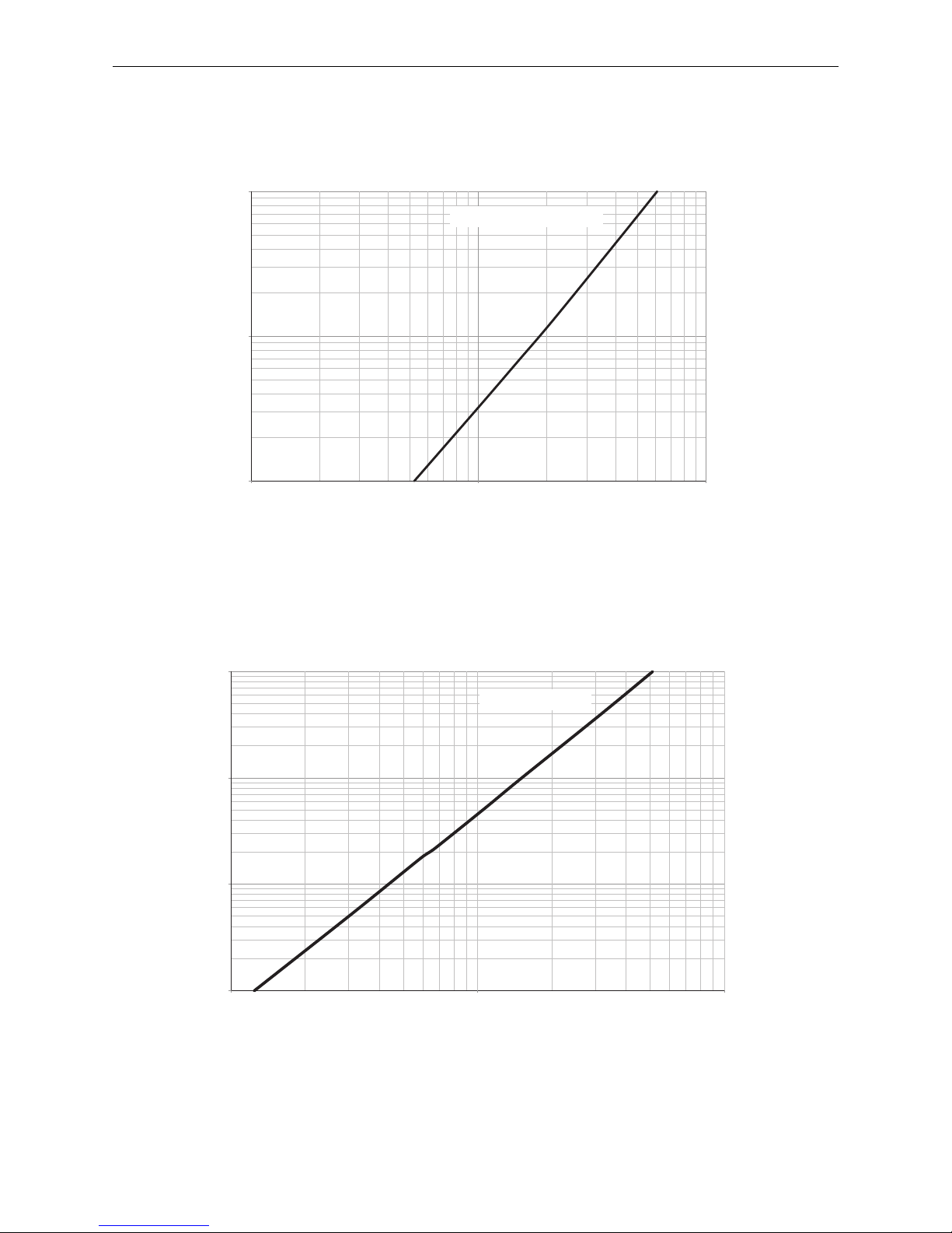
2.2.10 Water-side resistance (pressure loss)
Wood gasification boiler:
Diagramm 2 Water-side resistance – pellet boiler
Diagram 1 water-side resistance – wood gasification boiler
Pellet boiler:
1
10
100
100
1000
10000
0,1
1
10
100
100 1000 10000
Flow rate (l/h)
Wood gasification boiler
Pressure loss (mbar)
Flow rate (l/h)
Pressure loss (mbar)
Pellet boiler
13
2. For the Installer
1
Kesselnenngesamtleistung ist die Summe der gleichzeitig betriebenen Nennleistungen aller installierten Wärmeerzeuger im selben Heiz-/Aufstellraum.
2.3 Combustion air
An adequate supply of combustion air is absolutely essential. The combustion air is drawn directly from the installation room by the device, therefore the installation room must be adequately ventilated. The combustion air should
be directed to the vicinity of the boiler and
must be free from pollutants (gases, vapours, and dusts), otherwise
malfunctions and increased wear ( e.g., corrosion) may occur.
Attention!
The configuration of the entire system must comply with the requirements of regional legislation,
applicable regulations, standards and guidelines.
Applicable for Austria (excerpt from ÖNORM H 5170):
The minimum free cross-section area must be 5 cm2 per kW of the boiler‘s nominal total output1.
The ventilation opening to the outdoors for combustion air should be designed as follows:
– the flow of air must not be restricted in any way by the weather (e.g., snow, leaves),
– the free cross-section area remains the same when taking the cover grille, discs, etc. into consideration.
Applicable for Germany (excerpt from the Firing Ordinance, September 2007):
For hearths with a total nominal output of no more than 50 kW that are dependent on surrounding air, the combustion air supply will be sufficient providing that each installation room has an opening which vents to the atmosphere (with an unobstructed cross-section of at least 150 cm² or two openings of 75 cm² each, or pipes leading
outside with a technically equivalent cross-section).
Information!
Malfunctions or other issues caused by inadequate combustion air are not covered by the guarantee!
14
2. For the Installer
2.4 Installation sequence
2.4.1 Minimum service clearances for fire protection, cleaning, and
maintenance
It is essential to comply with the following minimum service clearances from flammable materials and for
connections, cleaning, and maintenance.
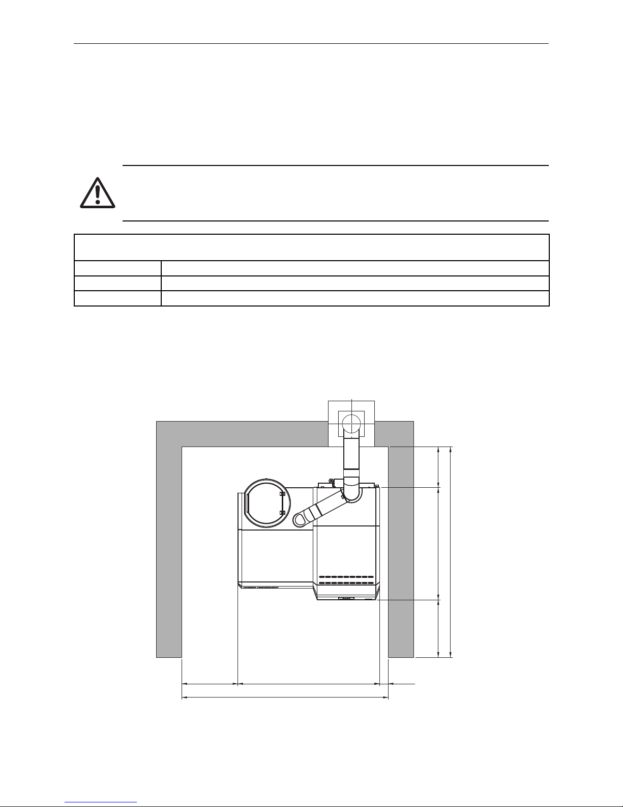
Attention!
Follow the installation guidelines for boiler rooms! The configuration of the exhaust line must
comply with technical fire protection requirements in accordance with the applicable regulations,
standards, and guidelines.
Minimum clearances between the exhaust pipe incl. exhaust probe or boiler outlet (connecting piece to flue)
and flammable parts
400
1
mm for an uninsulated exhaust pipe
100
1
mm for an insulated exhaust pipe (min. insulation thickness of 2 cm)
50
2
mm for approved, double-walled system flues
1
DIN V 18 160-1
2
in accordance with approval/identification of system flue
1393
1100
565
85 min. 550
min. 400
2028
2065
Fig. 6 DuoWIN – top view
All dimensions in mm:
Minimum room heights: 1850 mm

15
2. For the Installer
16
2. For the Installer
2.4.2 Transport to installation site
To avoid damaging the combustion chamber and/or the parts slipping, the appliance must be transported into the
building and installed without significant knocks or jolts. The warranty will be invalid if the appliance is damaged
or malfunctions due to incorrect transportation or installation.
The wood gasification boiler may only be transported upright and without cladding. It is easiest to transport using
a lift truck or by rolling on pipes. It is best to transport the boiler and integral fuel hopper to the installation site
inside the crate. If transporting via stairs etc., the boiler should be secured as is appropriate. For installation
dimensions and weights, see Fig. 8, 9, and section 5 of the technical data.
If it is not possible to transport inside the crate, we recommend using a hand cart and tension belt – see Fig. 14, 15.
Note!
A crane lug is on top of the boiler for transportation with winches. Pellet boiler: an M12 eyelet for a
crane hook (not included in the scope of supply) can be mounted to the threaded bolt of the screw
connection on the coasting surfaces cover. The weight can be reduced by removing easily dismantled
parts (e.g. doors, hook-in plates, burn-through plates, heating surface cleaning, etc. ).
The boiler can be installed directly on a fire-resistant surface and does not require a special foundation.
Boiler and integral fuel hopper in the crate
612
812
1161
660
767
6821
Fig. 8
Pellet boiler
Integral fuel hopper
with/without pellet feed
Boiler and integral fuel hopper without crate
Fig. 9
714
650 (BW 102/152)
720 (BW 212/262)
1146
584
592
1231
584
592
1471
Pellet boiler Integral fuel hopper
without pellet feed
Integral fuel hopper
with pellet feed
17
2. For the Installer
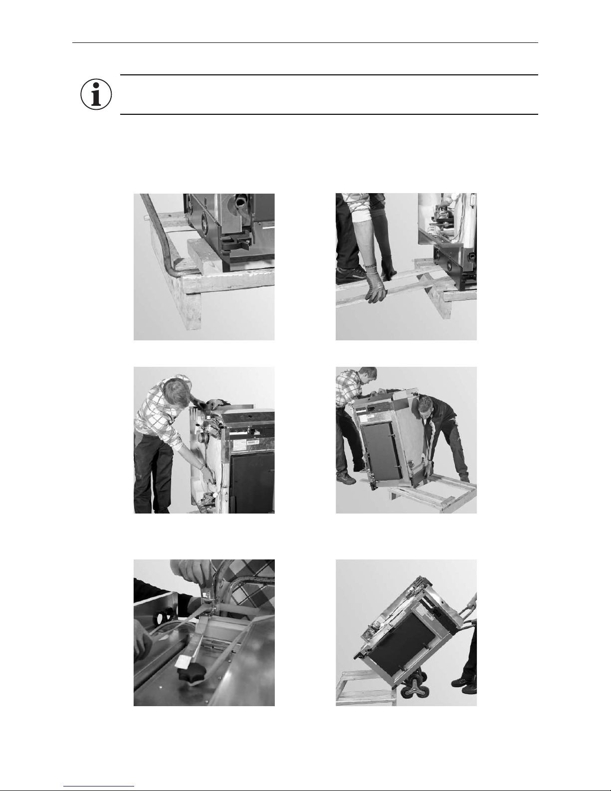
b) with hand cart and tension belt
Fig. 10 Remove 2 screws and the side pie-
ces of wooden frame
Fig. 11 Use planks from crate as ramp
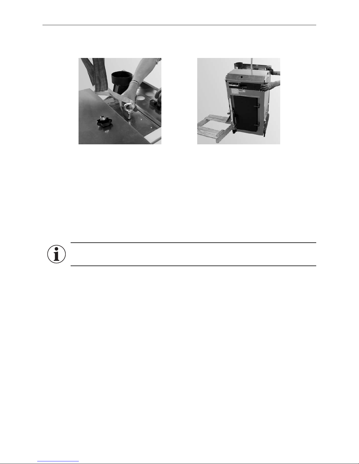
2.4.2.1 Remove boiler from pallet and transport to installation site
Information!
The base of the boiler is secured to the floor plate by 2 screws positioned on either side – Fig. 8.
a) by hand – Fig. 10–13.
b) with hand cart and tension belt – Fig. 14-15.
c) with eyelet and crane (not included in delivery) – Fig. 16-17.
a) by hand
Fig. 12 Grip position for auger tube and
flue outlets
Fig. 13 Push boiler off pallet
Fig. 14 Secure boiler to pushcart with
tension belt
Fig. 15 14 Lift the boiler off the pallet with
the hand cart
18
2. For the Installer
c) with eyelet and crane (not included in delivery)
Screw eyelet M12 (not included in scope of delivery) for the crane hook to the screw connection of the coasting
surface lid‘s threaded bolt. Lift boiler off pallet with the crane.
Fig. 16 Mount the eyelet (not included in
scope of delivery) for the crane hook
Fig. 17 Lift boiler off pallet
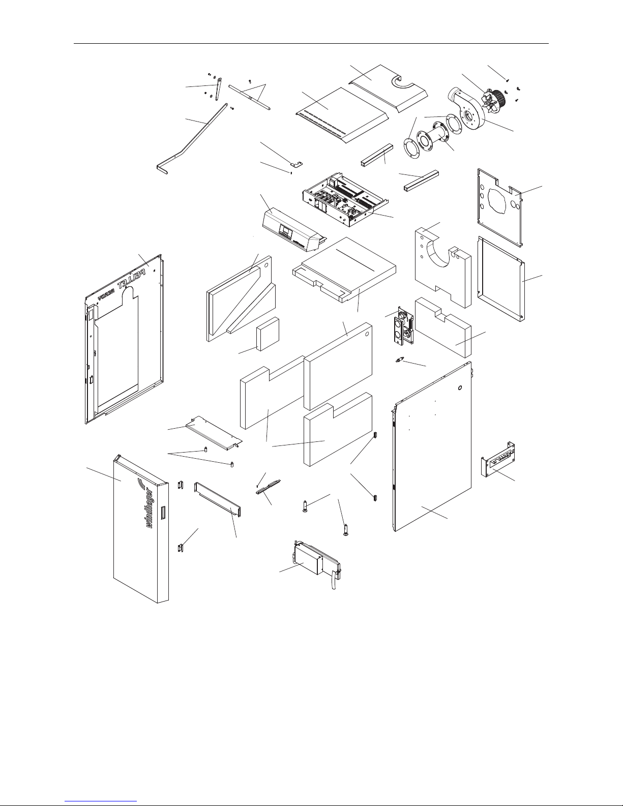
1 ........... Lower door hinge
2 ........... Carburisation gas duct
3 ........... Left side panel
4 ........... Right side panel
5 ........... Rear top wall
6 ........... Rear bottom wall
7 ........... Front boiler cover
8 ........... Rear boiler cover
9 ........... Hook-in plate ash pan
10 ......... Bottom insulation, left/right
11 ......... Top insulation, right
12 ......... Top insulation, left
13 ......... Insulation, left
14 ......... Top rear insulation
15 ......... Bottom rear insulation
16 ......... Top front insulation
17 ......... Cladding door
18 ......... Magnet retainer (2 pcs.)
19 ......... Carburisation gas duct attachment (2 pcs.)
20 ......... Control panel
21 ......... Upper door hinge
22 ......... Control panel
23 ......... Dog point screw (2 pcs.)
24 ......... Cable channel (2 pcs.)
25 ......... Lambda sensor
26 ......... Air control
27 ......... Set screws front (2 pcs.)
28 ......... Magnetic catch (2 pcs.)
29 ......... Blower seal
30 ......... Flue connection adapter – accessories
31 ......... Blower housing
32 ......... Flue gas blower
33 ......... Wing nugs
34 ......... Lighting door with automatic ignition – accessory
35 ......... Hanger – accessory
36 ......... Shaft for cleaning heating surfaces
37 ......... Shorter lever
38 ......... Lever for cleaning heating surfaces
2.4.3 Installation parts
Information!
All cladding parts must be fully fitted for air guidance and heat dissipation on the boiler.
19
2. For the Installer
21
2
4
5
6
7
8
9
10
11
14
15
16
17
28
19
20
1
22
23
22
24
25
26
27
18
29
30
31
32
33
34
35
36
37
38
3
12
13
Fig. 18 Parts for installation wood gasification boiler
20
2. For the Installer
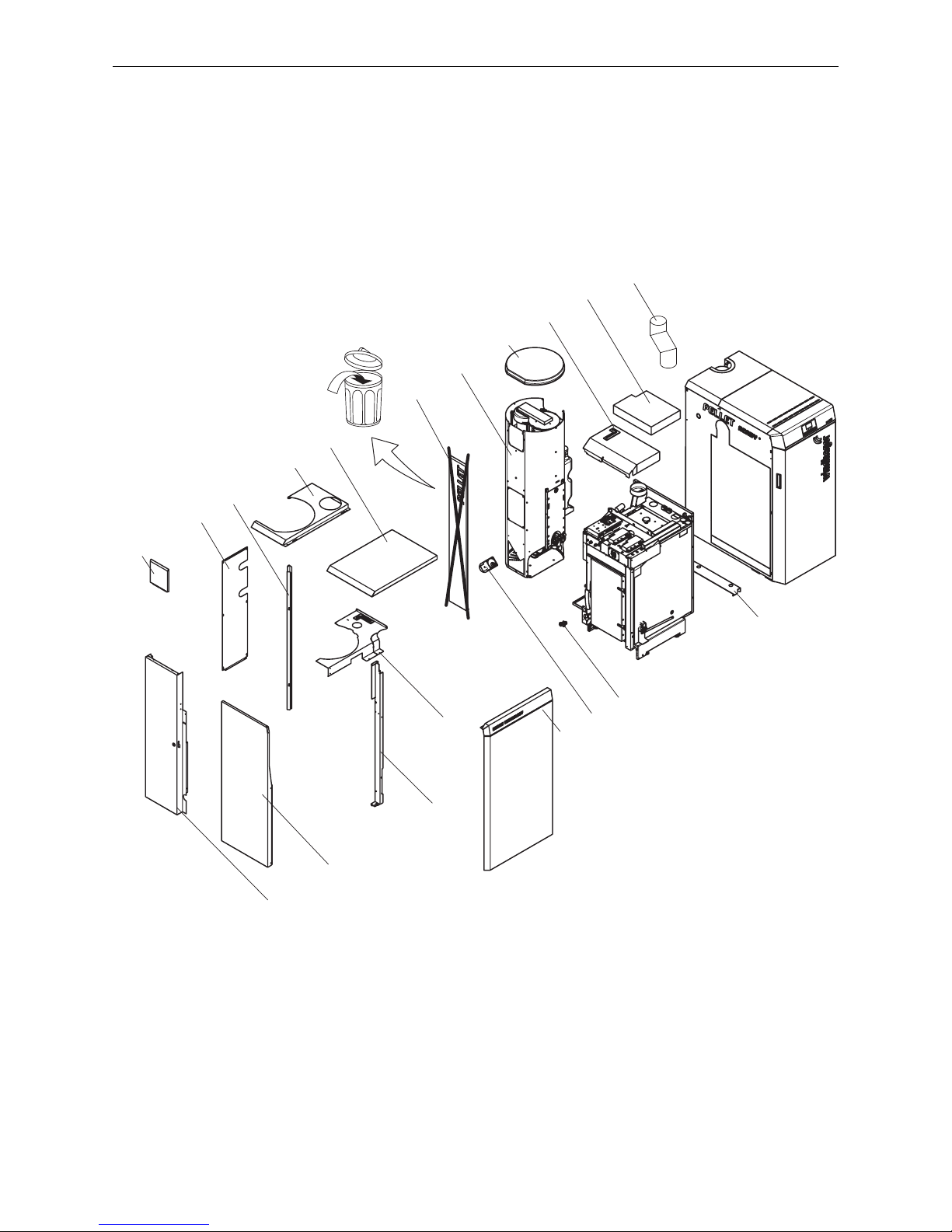
50 ......... Positioning bracket
51 ......... Filling and evacuation cock
52 ......... Integral fuel hopper
53 ......... Integral fuel hopper lidr
54 ......... Integral fuel hopper cover (not required)1
55 ......... Auger motor
56 ......... Control panel cover
57 ......... Coasting surface insulation
58 ......... Rear assembly bracket
59 ......... Top cladding
60 ......... Rear wall
61 ......... Cladding
62 ......... Bracket
63 ......... Panel front
64 ......... Cover on integral fuel hopper side
65 ......... Cover on pellet boiler side
66 ......... Cladding door
67 ......... Integral fuel hopper cover, only with automatic pellet feed
68 ......... Exhaust gas connection piece
53
52
67
60
64
54
65
58
57
56
61
66
62
59
55
51
63
50
68
Fig. 19 Parts for installation pellet boiler
1 ntegral fuel hopper cover is not required; have it removed professionally, no compensation!
21
2. For the Installer
2.4.4 Note before installation
Confirm hydraulic piping:
– Windhager hydraulic piping DUO 001 is used, or
– Hydraulic piping is completely installed on-site
Confirm flue gas connection:
– Windhager flue gas connection set DUO 002 is used, or
– Flue gas connection is completely installed on-site; see also point 2.4.5.
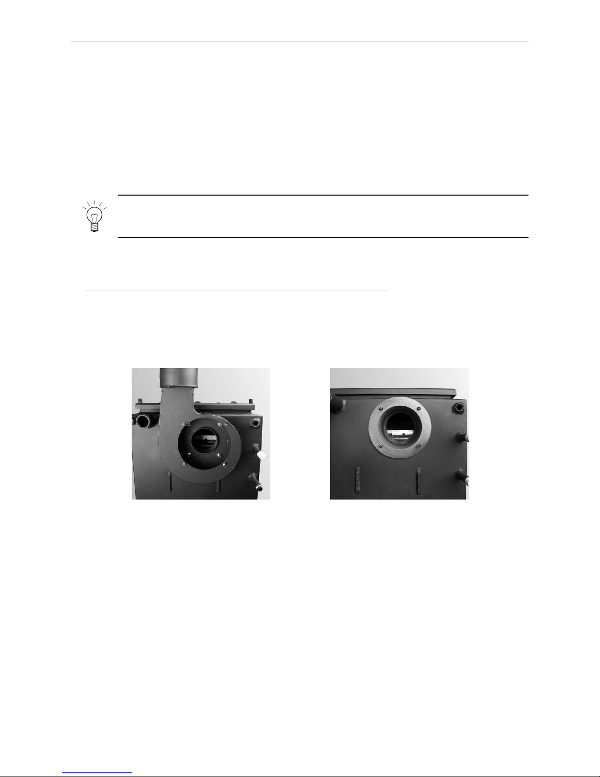
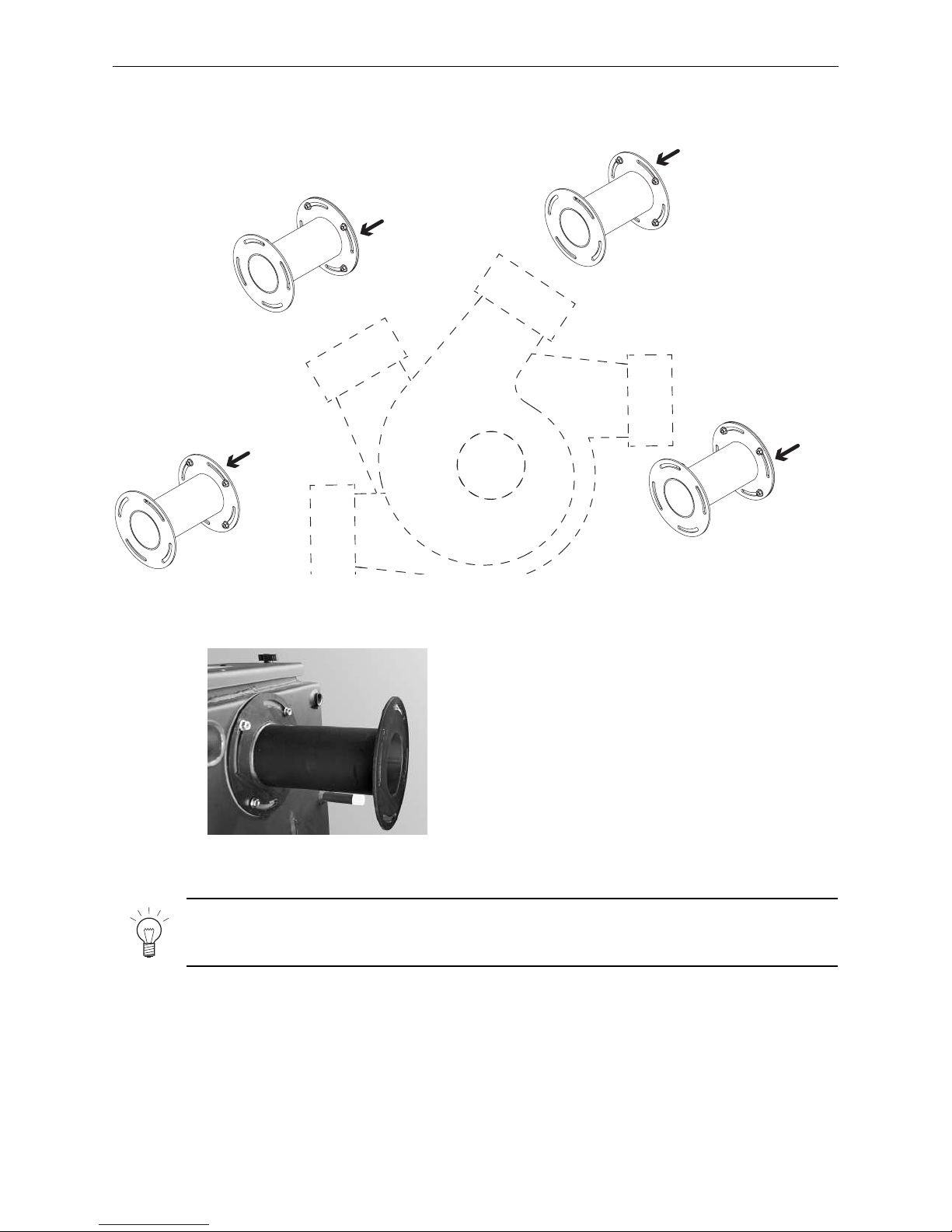
2.4.5 Wood gasification boiler: Installing the flue connection adapter
– Only for wood gasification boiler with flue connection adapter (accessories)
Standard installation of blower housing is directly on the boiler – Fig. 20 è flue connection at top.
With the adapter (accessories), the blower housing is located outside of the cladding – Fig. 23. The flue
connection is steplessly adjustable from left to right – Fig. 22.
– Unscrew 4 interior nuts in the blower housing (Fig. 20) and remove the housing. Do not remove the seal –
Fig.21.
Fig. 20 Blower housing directly on boiler –
standard
Fig. 21 Seal on boiler
Note!
If the wood gasification boiler LogWIN Klassik pellets ready is already installed, continue with section 2.4.27.
22
2. For the Installer
Note!
Do not screw the blower housing onto the adapter until the rear panel has been installed –
otherwise, the rear panel cannot be installed.
– Secure adapter on boiler, according to Fig. 22, with seal and 4 M8 nuts. Slot position depends on desired angle
of flue connection - Fig. 22, 23.
0°- 45°
45°- 90°
90°- 135°
135°- 180°
0°- 45°
45°- 90°
90°- 135°
135°- 180°
Fig. 22 Installation of adapter depending on angle of flue connection
Fig. 23 Adapter on the boilder (accessories)
Boiler side
Boiler side
Boiler side
Boiler side
23
2. For the Installer
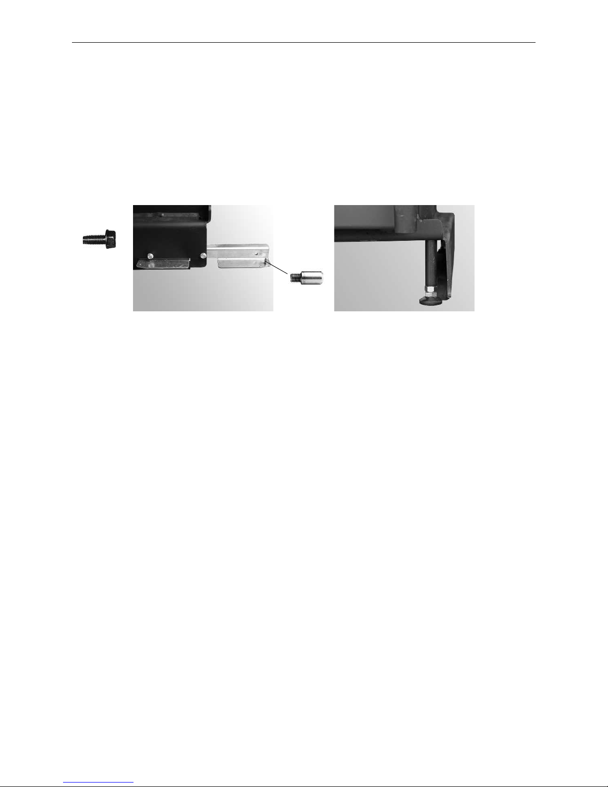
2.4.6 Wood gasification boiler: Mount the set screws, set door catch
Move the wood gasification boiler to its final installation position and use the set screws to align it inclined slightly
upwards towards the rear. If it is not possible to level the unit using only the rear set screws, two additional set
screws can be installed at the front – Fig. 25.
The cladding door and the boiler doors are designed for door catches on either the left or right. Standard delivery
always includes door catches on the left. The catches on the cladding door and boiler doors must be on the same
side. Prior to installing the set screws, the lower door hinge and the dog point screw for attaching the cladding
door must be mounted on either the left or right, depending on which side the door catches are to be located. –
Fig. 24.
Fig. 24 Install door hinge for cladding door
on the left or right
2 x
1 x
Fig. 25 Install two set screws in the front
 Loading...