

Page 1
WOOD / PELLETS
Operating Manual
12/2014 0094860/00
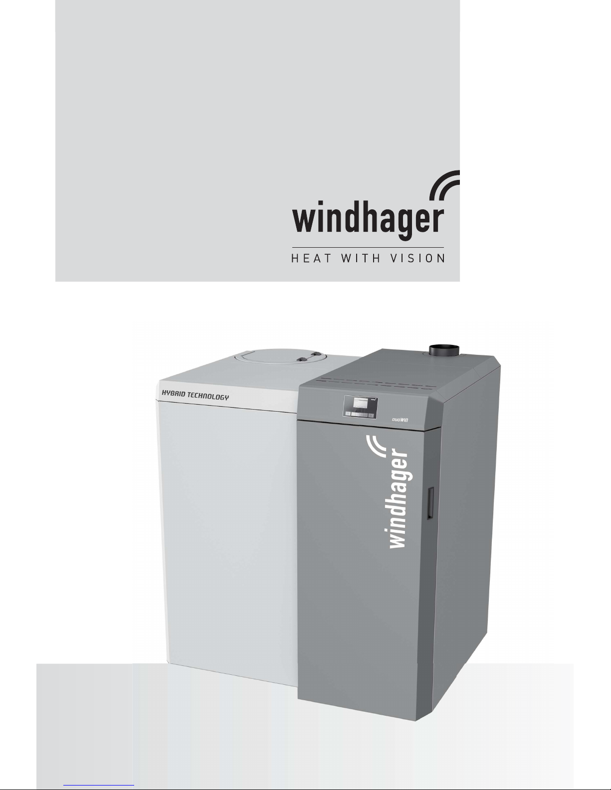
DuoWIN
with Hybrid Technology
Combined Heating with Wood and Pellets
For Single and Multiple Family Homes
Output Range: 4,3 to 30 kW
Page 2

2
Table of contents
Table of contents
1. Important Information for System Operators . . . . . . . . . . . . . . . . . . . . . . . . . . . . . . . . . . . . . 4
1.1 General information . . . . . . . . . . . . . . . . . . . . . . . . . . . . . . . . . . . . . . . . . . . . . . . . . . . . . . . . . . . . . . . . . . . .4
1.1.1 Manufacturer’s obligations . . . . . . . . . . . . . . . . . . . . . . . . . . . . . . . . . . . . . . . . . . . . . . . . . . . . . . . . . . . . . . . . . . 4
1.1.2 Installer’s obligations . . . . . . . . . . . . . . . . . . . . . . . . . . . . . . . . . . . . . . . . . . . . . . . . . . . . . . . . . . . . . . . . . . . . . . . 4
1.1.3 Operator’s obligations . . . . . . . . . . . . . . . . . . . . . . . . . . . . . . . . . . . . . . . . . . . . . . . . . . . . . . . . . . . . . . . . . . . . . . 4
1.1.4 Spare parts . . . . . . . . . . . . . . . . . . . . . . . . . . . . . . . . . . . . . . . . . . . . . . . . . . . . . . . . . . . . . . . . . . . . . . . . . . . . . . . . 5
1.2 Safety precautions . . . . . . . . . . . . . . . . . . . . . . . . . . . . . . . . . . . . . . . . . . . . . . . . . . . . . . . . . . . . . . . . . . . . . .5
1.3 Sources of danger . . . . . . . . . . . . . . . . . . . . . . . . . . . . . . . . . . . . . . . . . . . . . . . . . . . . . . . . . . . . . . . . . . . . . . .5
1.3.1 Power failure (or if the blower is not running) . . . . . . . . . . . . . . . . . . . . . . . . . . . . . . . . . . . . . . . . . . . . . . . . . . . . 5
1.3.2 Burner pot . . . . . . . . . . . . . . . . . . . . . . . . . . . . . . . . . . . . . . . . . . . . . . . . . . . . . . . . . . . . . . . . . . . . . . . . . . . . . . . . 5
1.3.3 Entering the pellet storage room/storage container . . . . . . . . . . . . . . . . . . . . . . . . . . . . . . . . . . . . . . . . . . . . . . 6
1.3.4 Combustion air . . . . . . . . . . . . . . . . . . . . . . . . . . . . . . . . . . . . . . . . . . . . . . . . . . . . . . . . . . . . . . . . . . . . . . . . . . . . 6
1.3.5 Wood gasification and pellet boiler connected to flue . . . . . . . . . . . . . . . . . . . . . . . . . . . . . . . . . . . . . . . . . . . . . 6
1.4 Fuel. . . . . . . . . . . . . . . . . . . . . . . . . . . . . . . . . . . . . . . . . . . . . . . . . . . . . . . . . . . . . . . . . . . . . . . . . . . . . . . . . . .6
1.4.1 Pellet boiler . . . . . . . . . . . . . . . . . . . . . . . . . . . . . . . . . . . . . . . . . . . . . . . . . . . . . . . . . . . . . . . . . . . . . . . . . . . . . . . 6
1.4.2 Wood gasification boiler . . . . . . . . . . . . . . . . . . . . . . . . . . . . . . . . . . . . . . . . . . . . . . . . . . . . . . . . . . . . . . . . . . . . . 7
1.5 Commissioning and maintenance . . . . . . . . . . . . . . . . . . . . . . . . . . . . . . . . . . . . . . . . . . . . . . . . . . . . . . . . . . 7
1.6 Functional test . . . . . . . . . . . . . . . . . . . . . . . . . . . . . . . . . . . . . . . . . . . . . . . . . . . . . . . . . . . . . . . . . . . . . . . . .8
1.7 Filling the pellet store . . . . . . . . . . . . . . . . . . . . . . . . . . . . . . . . . . . . . . . . . . . . . . . . . . . . . . . . . . . . . . . . . . . 8
2. Operation . . . . . . . . . . . . . . . . . . . . . . . . . . . . . . . . . . . . . . . . . . . . . . . . . . . . . . . . . . . . . . . . . . . 9
2.1 Wood gasification boiler: functional elements and operating controls . . . . . . . . . . . . . . . . . . . . . . . . . . .9
2.2 Pellet boiler: opening the cladding door . . . . . . . . . . . . . . . . . . . . . . . . . . . . . . . . . . . . . . . . . . . . . . . . . . . 10
2.3 Pellet boiler: functional description, function elements, and operating controls . . . . . . . . . . . . . . . . . .11
2.3.1 Pellet boiler with manual pellet feed . . . . . . . . . . . . . . . . . . . . . . . . . . . . . . . . . . . . . . . . . . . . . . . . . . . . . . . . . . 11
2.3.2 Pellet boiler with fully automatic pellet feed . . . . . . . . . . . . . . . . . . . . . . . . . . . . . . . . . . . . . . . . . . . . . . . . . . . . 12
2.4 Check before inital start-up . . . . . . . . . . . . . . . . . . . . . . . . . . . . . . . . . . . . . . . . . . . . . . . . . . . . . . . . . . . . .13
2.5 Filling the integral fuel hopper . . . . . . . . . . . . . . . . . . . . . . . . . . . . . . . . . . . . . . . . . . . . . . . . . . . . . . . . . . . 13
2.5.1 Manual filling . . . . . . . . . . . . . . . . . . . . . . . . . . . . . . . . . . . . . . . . . . . . . . . . . . . . . . . . . . . . . . . . . . . . . . . . . . . . . 13
2.5.2 Fully automatic filling . . . . . . . . . . . . . . . . . . . . . . . . . . . . . . . . . . . . . . . . . . . . . . . . . . . . . . . . . . . . . . . . . . . . . . 13
2.6 Wood gasification boiler heating operation - preparation, ignition or refilling, end of burning . . . . . .14
2.6.1 Heating mode preparation . . . . . . . . . . . . . . . . . . . . . . . . . . . . . . . . . . . . . . . . . . . . . . . . . . . . . . . . . . . . . . . . . . 14
2.6.2 Manual ignition (no automatic ignition) . . . . . . . . . . . . . . . . . . . . . . . . . . . . . . . . . . . . . . . . . . . . . . . . . . . . . . . . 15
2.6.3 Using automatic ignition . . . . . . . . . . . . . . . . . . . . . . . . . . . . . . . . . . . . . . . . . . . . . . . . . . . . . . . . . . . . . . . . . . . . 16
2.6.4 Replenishing fuel – continuing heating operation. . . . . . . . . . . . . . . . . . . . . . . . . . . . . . . . . . . . . . . . . . . . . . . . 18
2.6.5 Wood gasification boiler - end of burning . . . . . . . . . . . . . . . . . . . . . . . . . . . . . . . . . . . . . . . . . . . . . . . . . . . . . . 18
2.7 Heating system operation - pellet boiler . . . . . . . . . . . . . . . . . . . . . . . . . . . . . . . . . . . . . . . . . . . . . . . . . . . 19
2.7.1 MESplus system control . . . . . . . . . . . . . . . . . . . . . . . . . . . . . . . . . . . . . . . . . . . . . . . . . . . . . . . . . . . . . . . . . . . . 19
Page 3

3
Table of contents
3. Care, Cleaning, and Maintenance . . . . . . . . . . . . . . . . . . . . . . . . . . . . . . . . . . . . . . . . . . . . . . 20
3.1 Care of cladding and keyboard foil . . . . . . . . . . . . . . . . . . . . . . . . . . . . . . . . . . . . . . . . . . . . . . . . . . . . . . . .20
3.2 Cleaning and operating implements . . . . . . . . . . . . . . . . . . . . . . . . . . . . . . . . . . . . . . . . . . . . . . . . . . . . . .20
3.3 Cleaning the wood gasification boiler . . . . . . . . . . . . . . . . . . . . . . . . . . . . . . . . . . . . . . . . . . . . . . . . . . . . .21
3.3.1 During each fill: . . . . . . . . . . . . . . . . . . . . . . . . . . . . . . . . . . . . . . . . . . . . . . . . . . . . . . . . . . . . . . . . . . . . . . . . . . . 21
3.3.2 Weekly . . . . . . . . . . . . . . . . . . . . . . . . . . . . . . . . . . . . . . . . . . . . . . . . . . . . . . . . . . . . . . . . . . . . . . . . . . . . . . . . . . 22
3.3.3 Annually . . . . . . . . . . . . . . . . . . . . . . . . . . . . . . . . . . . . . . . . . . . . . . . . . . . . . . . . . . . . . . . . . . . . . . . . . . . . . . . . . 22
3.4 Cleaning the pellet boiler . . . . . . . . . . . . . . . . . . . . . . . . . . . . . . . . . . . . . . . . . . . . . . . . . . . . . . . . . . . . . . .26
3.4.1 Overview of intervals between cleaning (maintenance) . . . . . . . . . . . . . . . . . . . . . . . . . . . . . . . . . . . . . . . . . . . 26
3.4.2 Emptying ash pan; removing ash from underneath coasting surface . . . . . . . . . . . . . . . . . . . . . . . . . . . . . . . 27
3.4.3 Cleaning the combustion chamber and burner pot . . . . . . . . . . . . . . . . . . . . . . . . . . . . . . . . . . . . . . . . . . . . . . 28
3.4.4 Cleaning top coasting surfaces and blower wheel . . . . . . . . . . . . . . . . . . . . . . . . . . . . . . . . . . . . . . . . . . . . . . . 31
3.4.5 Water tank level . . . . . . . . . . . . . . . . . . . . . . . . . . . . . . . . . . . . . . . . . . . . . . . . . . . . . . . . . . . . . . . . . . . . . . . . . . . 32
3.4.6 Cleaning fuel hopper and feed unit flap . . . . . . . . . . . . . . . . . . . . . . . . . . . . . . . . . . . . . . . . . . . . . . . . . . . . . . . . 33
3.4.7 Confirm stage 1 cleaning or Confirm stage 2 cleaning - Reset cleaning request . . . . . . . . . . . . . . . . . . . . . . 34
3.5 Exhaust pipe to flue . . . . . . . . . . . . . . . . . . . . . . . . . . . . . . . . . . . . . . . . . . . . . . . . . . . . . . . . . . . . . . . . . . . .35
3.6 Pellet storage room or storage container . . . . . . . . . . . . . . . . . . . . . . . . . . . . . . . . . . . . . . . . . . . . . . . . . .35
3.7 Full service . . . . . . . . . . . . . . . . . . . . . . . . . . . . . . . . . . . . . . . . . . . . . . . . . . . . . . . . . . . . . . . . . . . . . . . . . . .36
4. Emissions Measurement - Wood Gasification Boiler . . . . . . . . . . . . . . . . . . . . . . . . . . . . . . 37
4.1 Preparation . . . . . . . . . . . . . . . . . . . . . . . . . . . . . . . . . . . . . . . . . . . . . . . . . . . . . . . . . . . . . . . . . . . . . . . . . . .37
4.2 Heating . . . . . . . . . . . . . . . . . . . . . . . . . . . . . . . . . . . . . . . . . . . . . . . . . . . . . . . . . . . . . . . . . . . . . . . . . . . . . . .37
4.3 Measurement . . . . . . . . . . . . . . . . . . . . . . . . . . . . . . . . . . . . . . . . . . . . . . . . . . . . . . . . . . . . . . . . . . . . . . . . . 37
5. EG-Declaration of Conformity . . . . . . . . . . . . . . . . . . . . . . . . . . . . . . . . . . . . . . . . . . . . . . . . .38
5.1 Wood gasification boiler . . . . . . . . . . . . . . . . . . . . . . . . . . . . . . . . . . . . . . . . . . . . . . . . . . . . . . . . . . . . . . . . .38
5.2 Pellet boiler . . . . . . . . . . . . . . . . . . . . . . . . . . . . . . . . . . . . . . . . . . . . . . . . . . . . . . . . . . . . . . . . . . . . . . . . . . .39
Warranty . . . . . . . . . . . . . . . . . . . . . . . . . . . . . . . . . . . . . . . . . . . . . . . . . . . . . . . . . . . . . . . . . . . . . 40
Page 4

4
1. Important Information for System Operators
1. Important Information for System Operators
Dear Heating System Owners,
We would like to congratulate you on your new environmentally friendly boiler system. With the purchase of this
high-quality product by Windhager, you have selected a system that provides high comfort levels and optimised
fuel consumption while utilising an environmentally friendly renewable fuel. Your boiler was manu-factured under
strict ISO 9001 certified standards of production control, subjected to extensive tests, and all of its components
are recyclable.
On the following pages, we have provided specific information and important tips regarding system operation,
unit functions, and cleaning.
The DuoWIN hybrid boiler constitutes the LogWIN Klassik pellet ready wood gasification boiler and the BioWIN 2
pellet boiler with a shared InfoWIN
PLUS
display and operating unit.
Operation of the boiler together with the InfoWIN
PLUS
display and operating unit is described in a separate operating manual. Please also pay close attention to these instructions. Familiarity with the material in this document
will allow you to enjoy long-term operation of the unit. We wish you all the best with your Windhager boiler!
1.1 General information
1.1.1 Manufacturer’s obligations
Our products are manufactured in accordance with the essential requirements of the various applicable guidelines.
They therefore carry the -label and are supplied with all the required documentation.
Technical details are subject to change.
We as the manufacturer cannot be held liable in the following cases:
– Incorrect use of the unit
– Failure to perform proper maintenance
– Incorrect installation of the unit
1.1.2 Installer’s obligations
As the person responsible for installing the unit, the installer must comply with the following instructions.
– Read and follow all instructions supplied with the unit.
– Carry out installation in accordance with the regulations and specifications of the applicable standards.
– Explain to the operator how the system works.
– Make the operator aware of his obligation to inspect and maintain the unit.
– Hand over all operating instructions to the operator.
1.1.3 Operator’s obligations
To ensure that the unit gives optimum service, the operator must follow these instructions:
– Read and follow the instructions in the operating manual.
– Installation and commissioning must be performed by appropriately qualified technicians.
– Make sure the installer explains how the system works.
– Perform all the necessary checks and maintenance.
– Keep the manuals in good condition and store them near the unit.
This unit is not intended for use by persons (including children) who have physical or mental disabilities or sensory impairment or who have no experience or knowledge of the correct use of the unit, unless supervised or
trained by a person responsible for their safety. Children must be supervised around the boiler to ensure they
do not touch or interfere with the unit.
Page 5
5
1. Important Information for System Operators
1.1.4 Spare parts
For spare parts, please contact the Customer Service partner or send an email to [email protected]
or phone tel. +43(0)6212/2341-268.
1.2 Safety precautions
This boiler and related accessories are state of the art and meet all applicable safety regulations. This boiler
and all accessories operate using 230 V AC electrical current. Improper installation or repair can result in a lifethreatening electric shock. Installation may only be performed by appropriately qualified technicians.
Caution symbols
Please take careful note of the following symbols in this operation manual and on the boiler.
Please note: risk of crushing from rotating auger.
If you have to touch these parts, always de-energise the boiler.
Hot surface warning: risk of burns!
Before touching these surfaces, turn off the boiler and let it cool.
Attention!
Ignoring the warnings identified can lead to personal injury.
Information!
Ignoring the warnings identified can lead to malfunction of, or damage to the boiler or heating
system.
Note!
The blocks of highlighted text provide information and tips for operation.
1.3 Sources of danger
1.3.1 Power failure (or if the blower is not running)
Attention!
Do not open the combustion chamber door, as doing so will increase the risk of blowback. The
control unit initiates a self-test following a power failure during combustion, and then operation
continues automatically.
1.3.2 Burner pot
Attention!
Never add pellets to the burner pot by hand. Excessive pellets will result in poor combustion and
ignition. Too much volatile gas in the combustion chamber may result in an explosion.
Page 6

6
1. Important Information for System Operators
1.3.3 Entering the pellet storage room/storage container
All energy sources are subject to safety regulations, which must be observed when working with fuels, heating
systems, and storage rooms. This also applies to pellet storage.
After the storage room is filled, odourless carbon monoxide (CO) may be produced, and there may be insufficient
oxygen present. For this reason, do not enter the pellet storage room for 6 weeks after it has been filled. Only
persons trained for working in confined spaces may enter the storage room for the purpose of measuring gas
levels before any work is carried out.
Please also follow the instructions on the sticker:
– No access to unauthorised persons, keep children away from the pellet store!
– Ensure sufficient ventilation before entering. Keep the door open while inside.
– Only enter the storage room under the supervision of a second person standing outside.
– No smoking, flames, or other sources of ignition are permitted.
– Risk of injury from moving parts.
– Pellet boilers must be turned off at least 15 minutes before filling.
– Fill in accordance with the instructions of the boiler and pellet suppliers.
– Protect pellets from moisture.
If you feel unwell, leave the storage room immediately and seek medical advice.
Attention!
Do not attempt to enter an unventilated storage room (particularly buried tanks).
1.3.4 Combustion air
Never seal openings that have been provided for ventilation!
1.3.5 Wood gasification and pellet boiler connected to flue
If the wood gasification and pellet boiler is connected to a flue, all cladding doors, combustion chamber doors as
well as the filling, ignition and ash doors and cleaning openings must be closed when the boiler is in operation.
Otherwise flue gas discharge can exit via open doors or cleaning openings.
1.4 Fuel
1.4.1 Pellet boiler
To ensure that your new heating system provides long-term reliable service, the following must be observed:
Quality of pellets must be in accordance with EN ISO 17225-2 A1:
The quality of the pellets is an important factor in achieving optimum operation of the heating system. When
buying pellets, ensure that they meet the quality standards of EN ISO 17225-2 A1 (or ÖNORM M7135 / DINplus).
For maximum reliability, purchase pellets from manufacturers with EN-Plus certification (or DIN-Plus, ÖNORM
M7135 or UZ38), as they are required to perform ongoing internal quality controls.
Diameter: 6 mm; Length: 10 – 40 mm; max 1 up to 45 mm
Inform your pellet supplier of these quality requirements before ordering, and request confirmation upon delivery that the fuel meets this standard.
Consequences of quality fluctuations:
Pellets are 100% unprocessed wood, so minor fluctuations in fuel quality are expected and reflect the natural origins
of the material. These quality fluctuations affect the level of dirt and ash content. Therefore, the flue cleaning and ash
removal intervals may vary from one delivery to the next.
Any reduction in cleaning intervals as a result of fluctuations in pellet quality cannot be claimed as part of a repair
under warranty!
Page 7
7
1. Important Information for System Operators
1.4.2 Wood gasification boiler
The boiler is suited for burning wood in the form of unprocessed firewood. The water content of the fuel must be
between 15 – 25 %. General guidline: wood should be stored for appr. 2 years. The effects of any deviations from
these guidelines should be taken into account.
– ½ m split logs: 50 – 53 cm long, approx. 8 to max. 15 cm edge length. If lengths vary dramatically ( e.g., 1/3
m) undertake adapted filling! Round logs must always have a Ø of more than 8 cm!
– Wood briquettes: ignition with coarse wood briquettes, according to ÖNORM M7135 or DIN 51731.
– Residual wood: ignition of residual wood such as timber, boards, posts, etc. is permitted, as long as the
wood has not been treated with wood preservers or other chemicals containing halogenated
organic compounds or heavy metals (among such prohibited residual materials are, in par-
ticular, construction and demolition waste). Wood fuel must be added as appropriate to the
material!
Unsuitable fuels:
– Solid fossil fuels: black coal, brown coal, coke, peat, etc.
– Wood chips, wood shavings, pellets, straw, grain, wood from short-rotation forestry etc.
– Do not use plastics, PVC panels, sawdust, impregnated/glued wood residues, or similar – these cause boiler
corrosion and are prohibited by the Federal Air Purity Act.
Attention!
Do not use fuels with high dust levels, such as grinding dust or sawdust – risk of explosion!
1.5 Commissioning and maintenance
Windhager Customer Service or one of our customer service partners must commission your new boiler. All
systems will be thoroughly checked, and you will also benefit from detailed information provided by the system
installer. Installation and routine maintenance performed by Windhager Customer Service or a customer service partner will guarantee the optimal performance and service life of your boiler system. This will also ensure
that this technologically advanced system provides the benefits of safe, environmentally friendly, and energysaving operation.
The following preconditions must be met before ordering the boiler commissioning:
1.) Boiler installed correctly.
2.) System fully electrically wired.
3.) System rinsed, filled, and vented – heat demand must be present.
4.) Boiler connected to domestic water and filled.
5.) Sufficient quantity of fuel available (pellets, split logs, oil, or gas).
6.) The customer must be present during commissioning.
The commissioning cannot be carried out if any of these items are incomplete or neglected. The customer
will be charged for any unnecessary costs arising as a result.
Start-up and maintenance by Windhager customer service or a customer service partner are part of the
guarantee requirements of the enclosed “guarantee limitations”.
Note!
Wood gasification boiler: When the boiler is heated up for the first time, unpleasant smells may
occur from gas emissions due insulation or paint residue being burnt off. Therefore, ensure that
the boiler room/installation room is well vented. Condensation may also form near the coasting
surfaces, and the combustion chamber temperature may only increase after a delay.
Note!
Pellet boiler: During the first few weeks after start-up, condensation can occur in the combustion
chamber, ash chamber, and on the heating surfaces. This has no effect on the boiler‘s function and
service life.
Page 8
8
1. Important Information for System Operators
1.6 Functional test
EN 12828 and ÖNORM B8131 require that the function of the system and related safety equipment be checked
and certified yearly by a qualified technician (installer, heating system contractor).
The heating water condition must be checked (ÖNORM H 5195) by a heating expert (installer) (see BioWIN assembly instructions – heating water) at two-year intervals; this is to prevent corrosion and sediment accumulation in
the heating system and boiler. For systems using more than 1,500 litres of water (e.g., systems with accumulator
tanks), this inspection is required on an annual basis.
In the event of repair work requiring a change of water in the heating system, the heating water is to be checked
within 4 to 6 weeks after the repair work.
Corrosion and sediment resulting from incorrectly treated heating water are not covered by the guarantee and
warranty.
1.7 Filling the pellet store
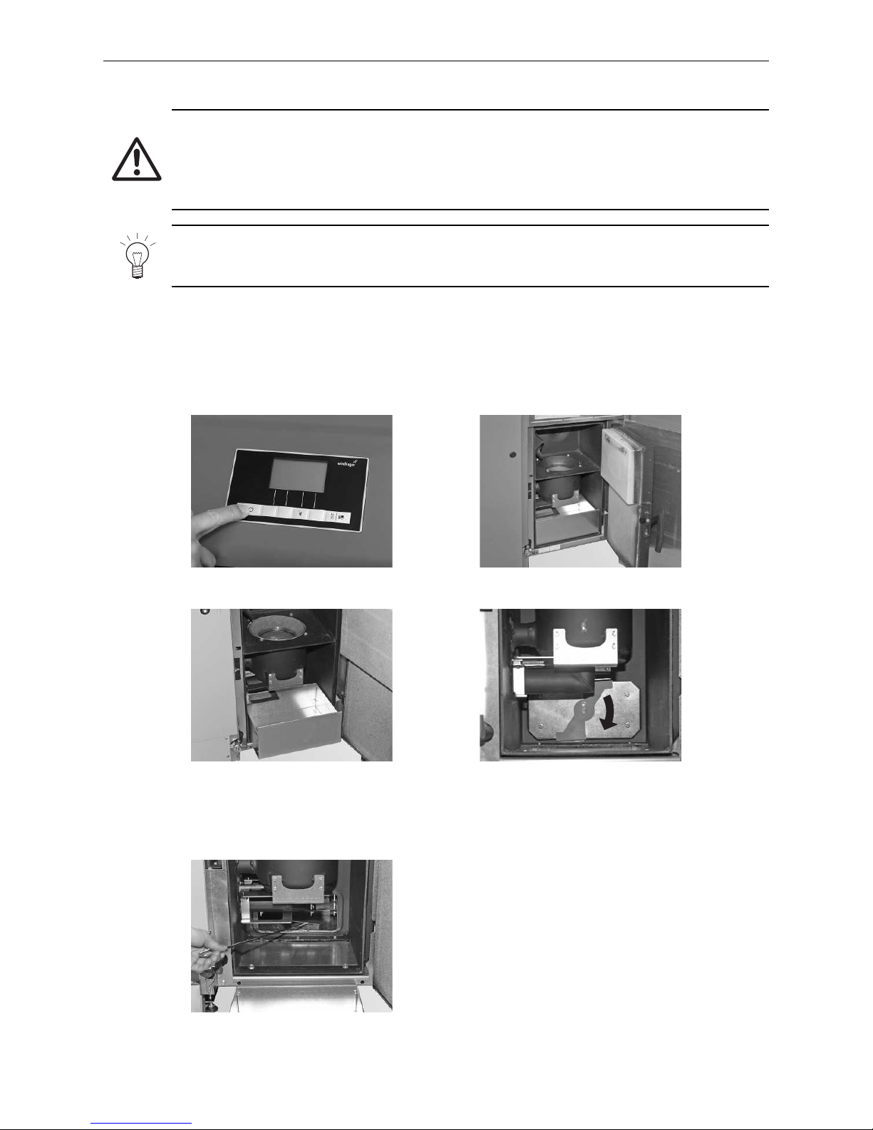
Attention!
The pellet flue-connected stove must be turned off correctly at least 15 minutes before the store is
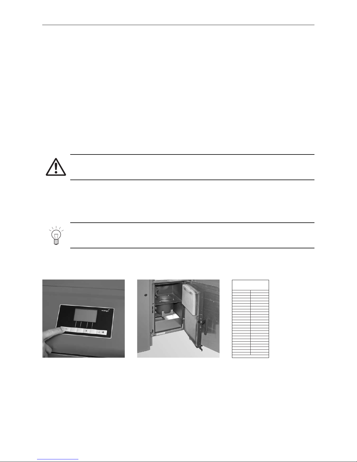
filled – Fig. 2. Press the ON/OFF button. Never turn off using the emergency OFF switch!
Pressing any button will turn on the display. The boiler is only turned off when the ON/OFF button is pressed
after the display is turned on. Wait until burnout mode has finished (this will not be indicated on the display) and
open the combustion chamber doors.
During filling, negative pressure is created in the pellet store, which can cause burn-back in the pellet boiler.
Therefore, the boiler must be prevented from operating during the filling procedure.
Tip!
To prevent negative pressure arising in the pellet boiler, open the combustion chamber door (see
Fig. 3 and also section 2.2) and leave open during the filling process.
Every time the store is filled, the date and volume should be added to the “Storage room fill“ sticker – Fig. 4.
Fig. 2 Turning off boiler Fig. 3 Opening combustion chamber
door during the filling process
002357/00 01/2010
Befüllung Lagerraum
Filling date and volume
Remplissage du silo de stockage
Datum/Date/Date
Menge/Volume/Quantité
kg
kg
kg
kg
kg
kg
kg
kg
kg
kg
kg
kg
kg
kg
kg
kg
kg
kg
kg
kg
kg
kg
kg
Fig. 4 “Storage room fill“ sticker on the
storage room door
Page 9
9
2. Operation
2. Operation
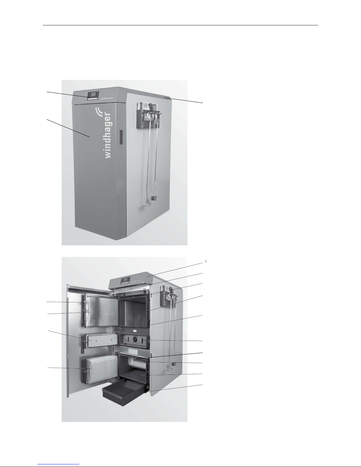
2.1 Wood gasification boiler:
functional elements and operating controls
1 ........... Cladding door
2 ........... InfoWIN
PLUS
3 ........... Rear boiler cover – the cleaning cover
for coasting surfaces is underneath
5 ........... Ash door
6 ........... Lighting door
7 ........... Filling door
8 ........... Hook catch for filling door
9 ........... Cladding flap – the MES modules, rating
plate, fuse and safety temperature
limiter are underneath
10 ......... Cladding door switch
11 ......... Carbonisation gas extraction
12 ......... Filling chamber with hook-in plates
13 ......... Vertical grate
14 ......... Thermocontrol sensor
15 ......... Combustion chamber
16 ......... Ash chamber
17 ......... Ash pan
18 ......... Lever for cleaning heating surfaces
Supplied as standard:
– Instruction booklets
– Scratcher (Wood gasification boiler)
– Ash pan
Optional accessories:
Cleaning set EWK 020
– Hanger (for installation on the wall or boiler
side panel)
– Spatula
– Cleaning brush
– Poker
Fig. 5 Wood gasification boiler
Fig. 6 Wood gasification boiler; open filling, lighting, and ash door
2
1
8
7
6
5
3
9
Page 10
10
2. Operation
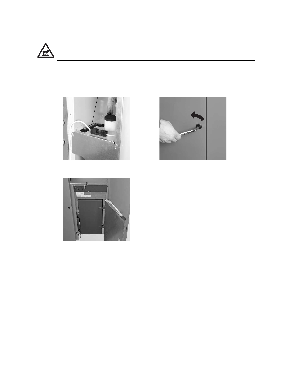
2.2 Pellet boiler: opening the cladding door
Hot surface warning: risk of burns!
Before opening the cladding door of the boiler, ensure that it is turned off via the On/Off switch (see
Fig. 2) and completely cooled (nothing shown on display).
– Remove the Allen key from the back of the filling pipe of the water tank – Fig. 7.
– Insert Allen key, turn a quarter turn to the left and open the cladding door – Fig. 8, 9.
Fig. 7 Allen key Fig. 8 Opening the cladding door with the
Allen key
1/4
Fig. 9 Cladding door open
Allen key
Page 11

11
2. Operation
2.3 Pellet boiler: functional description, function elements,
and operating controls
The pellet boiler and the Modular Energy System MES combine to form a perfect unit. The pellet boiler automatically ignites when the control system signals a heating requirement. Following “purging” (safety function),
ignition starts and the pellet metering auger turns on. The burner pot is automatically filled with pellets. When
flame formation has been detected (by the thermocontrol sensor), the boiler enters flame stabilisation mode
and then control mode (modulation mode) and keeps to the specified boiler temperature setpoint. The boiler
enters burnout mode if the heat consumed drops below the minimum nominal thermal output or no heating
requirement is signalled by the control system. The blower continues to run until the burner pot has cooled
down.
2.3.1 Pellet boiler with manual pellet feed
The integral fuel hopper is loaded by hand. The heating surfaces are cleaned manually using the cleaning lever.
The cleaning residues from the heating surfaces and the combustion residues from the burner pot drop into the
ash pan. In the event of a cleaning request, the ash must be removed by hand.
Page 12

12
2. Operation
2.3.2 Pellet boiler with fully automatic pellet feed
Version as sections 2.3.1, but in addition with fully automatic pellet feed
The pellet feed uses a maintenance-free suction turbine to automatically fill the pellet boiler integral fuel
hopper from a pellet storage room or storage container. The pellet feed is turned on by the lower fill level switch
(proximity switch) in the integral fuel hopper, or at the end of the enable time or the beginning of the start time,
and runs until the integral fuel hopper is full. Filling is not started if the boiler is in heating operation or the feed
signal has been blocked by the control unit (outside of the enable time, e.g., at night). If the boiler is operating
when filling is necessary, the boiler switches to burnout mode.
When there are several suction probes, switching to the suction probes is executed automatically. The system
changes to the next suction probe after the integral fuel hopper has been filled a certain number of times. Thus,
the storage room is emptied as evenly as possible.
Page 13

13
2. Operation
2.4 Check before inital start-up
a) System pressure (heating water pressure): The system must be filled and vented. When the system is cold,
the pressure should be at least 1.0 bar (maximum 1.8 bar). If you have any questions, your installer will gladly
answer them.
b) Ventilation: Ensure that the boiler room is well ventilated. The air supply must be as free of dust as possible.
c) Flue: Please have the chimney sweep check the flue regularly, and clean it, if necessary.
d) Barriers: Check that the barriers installed in the heating system are set correctly.
e) Accumulator tank: If the temperature shown on the central thermometer is already 70°C, do not continue
heating or replenish any fuel!
f) Thermal process safeguard: Check discharge funnel. Outflow must not drip.
g) Water tank: For level check in water tank for burn-back safeguard – see section 3.4.5.
2.5 Filling the integral fuel hopper
2.5.1 Manual filling
Open integral fuel hopper cover and fill hopper up to max. 1 cm below the edge. Close the cover.
2.5.2 Fully automatic filling
The integral fuel hopper is filled by the fully automatic pellet feed. Windhager Customer Service or the customer
service partner will fill the hopper for the first time during commissioning, and will start the boiler and familiarise
the customer with the operation and cleaning of the boiler, using the operating manual for reference.
Page 14
14
2. Operation
2.6 Wood gasification boiler heating operation -
preparation, ignition or refilling, end of burning
Attention!
High outside temperatures or direct sunlight on the flue can lead to gases being discharged into the
boiler/installation room, due to an insufficient flue draught during the start-up phase.
Flue gases poise threats of life-threatening poisoning or risk of explosion!
Tip: Organise the start-up times during cooler hours of the morning or evening. With the support
of your chimney sweep, ensure that the boiler system functions properly when in the conditions
mentioned above!
Important note before igniting or replenishing fuel:
Do not ignite or replenish fuel unless adequate heat consumption is ensured, i.e.:
– Check the “accumulator temperature” on the central thermometer. Do not ignite or replenish fuel if 70°C or
higher is displayed.
– Open the manual mixing valve, do not turn off the radiators.
– Correct amount of fuel (boiler only ¼ – ½ full during the transiational period).
Information!
A correctly sized accumulator tank is essential for proper operation.
2.6.1 Heating mode preparation
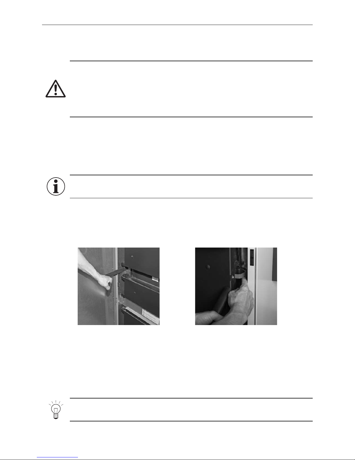
1.) During every fill period, press the lever for cleaning heating surfaces around 5–10 times – Fig. 12.
2.) Open the cladding door. Blower starts. Open the filling door (top door) until it makes contact with the lock -
lift the hook catch to fully open the filling door – (Fig.13).
Fig. 12 Pressing lever for cleaning
heating surfaces 5–10 times
Fig. 13 Opening the filling door lock
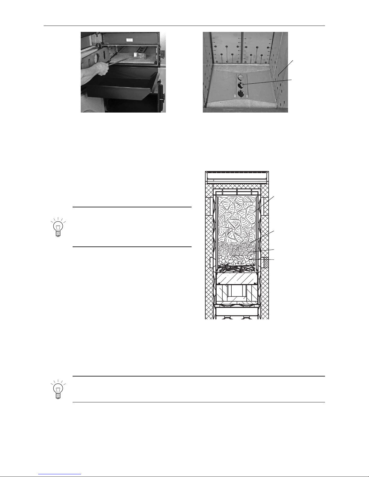
3.) Attach ash pan at height of lighting door (central door) in the intended hook-in plate – Fig. 14.
4.) Open the lighting door and vertical grate; evenly distribute the remaining ash in the filling chamber (Fig.14).
Check whether the holes in the lateral hook-in plates and burnthrough opening (Fig. 15) are clear.
If the holes are not clear, use the installed scraper to unblock them and/or remove excess ash from the filling
chamber. Note: unburned wood charcoal can still be used
Note!
The boiler should NOT, under any circumstances, be completed vacuumed before each heating process!
Page 15
15
2. Operation
Fig. 14 Attaching ash pan, removing ash Fig. 15 Filling chamber, holes in hook-in
plate, burnthrough opening
Holes in the
hook-in plates
Burnthrough
opening
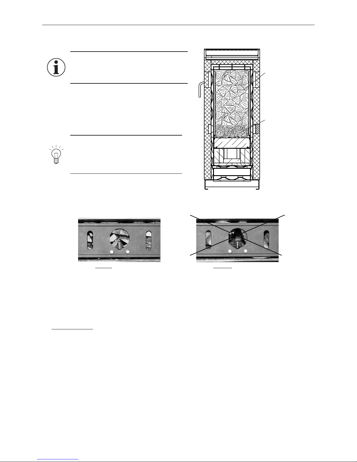
1.) First, arrange a layer of dry kindling. Top with another
layer of crushed paper/cardboard1. The burnthrough
opening must remain clear.
2.) Add smaller sized split logs, then larger split logs, and
fill the filling chamber as required – Fig. 16.
Note!
After ignition, do not open the filling door except to replenish fuel. This ensures the fuel will burn
evenly without disruptions, and extends the replenishment intervals.
Note!
To ensure clean combustion and quick ignition, fill the filling chamber at least halfway
and always prepare the basic firebed with
½ m pieces of wood.
3.) Close the filling door.
4.) Light the paper1 while the lighting door and vertical
grate are open.
Tip: To simplify lighting, add a little more paper1 at the
front.
5.) Close the vertical grate.
6.) Press the information button on the InfoWIN
PLUS
to display the combustion chamber temperature. Once the
temperature in the combustion chamber reaches 500
°C, close the lighting and cladding doors. This automatically starts the heating program.
2.6.2 Manual ignition (no automatic ignition)
Tip: If a lighting noise cannot be clearly heard, the burnthrough opening is probably covered or the fuel is
placed in such a way that excessively large cavities are present. To improve ignition, clear the burnthrough
opening.
1
Switzerland: for reasons of air hygiene (LRV), fire-lighters must be used instead of paper/cardboard.
Fig. 16 Section through the filling chamber
Hardwood or softwood
logs - edge length:
8 – 15 cm
Softwood logs - edge
length: 3 – 4 cm
Crumpled newspaper
1
Kindling
Page 16
16
2. Operation
1.) Close vertical grate.
2.) Add smaller sized split logs, then larger split logs,
and fill the filling chamber as required – Fig. 17.
Before closing the lighting door, ensure that there is
wood just in front of the ignition opening– Fig.18.
Fig. 17 Section through the filling chamber
Hardwood or softwood
logs edge length
8 – 15 cm
Hardwood or softwood
logs edge length
3 – 4 cm
Note!
For reliable and efficient ignition, it is important that wood is in front of the ignition
opening. Always prepare the basic firebed
with ½ m pieces of wood.
2.6.3 Using automatic ignition
1
3.) Close lighting door, filling door, and cladding door.
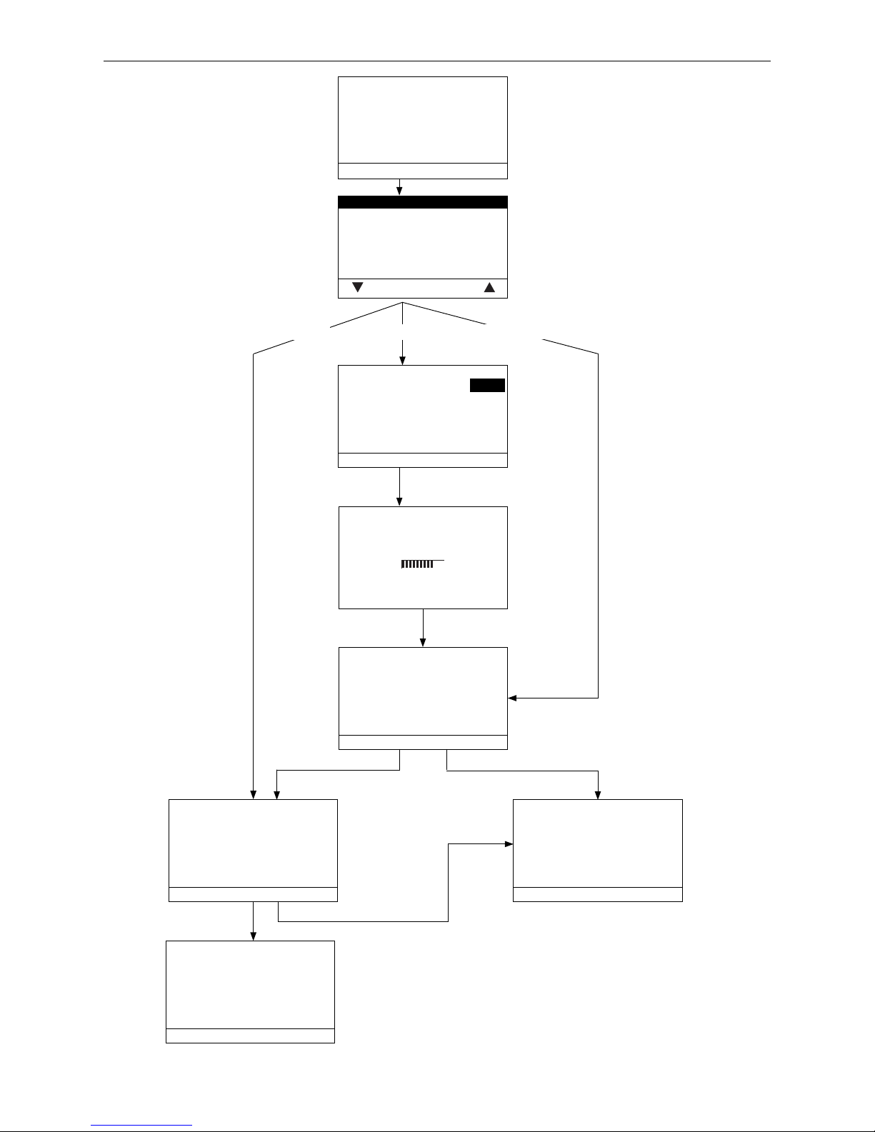
„Ignition“ displayed on InfoWIN
PLUS
– Fig. 20.
4.) Press Ignition button to display „Instant“, „With off period“ and „Automatic“ – Fig. 21.
5.) Use the Arrow buttons to select the desired ignition type and confirm with the choose button – Fig. 21.
Types of ignition:
„Instant“: The ignition phase begins immediately after selection.
„With off period“: Press the + or – buttons to change the time in 15 min. steps. Press Save to confirm this
choice – Fig. 22.
The ignition phase starts only once the set time has elapsed and a heating request has
been generated by MESplus control or an external ignition request.
„Automatic“: The ignition phase begins when there is a heating request from the MESplus control or an
external ignition request.
Information!
Before filling, ensure no embers are present
in the filling chamber – uncontrolled ignition
possible!
1
Only for LogWIN with automatic ignition (accessory).
Fig. 18 Correct: Wood placed in front of
the ignition opening
Fig. 19 Incorrect: No wood in front of the
ignition opening
Page 17
17
2. Operation
Boiler temperature
Start procedure
Info Ignition Cancel Menu
22
°C
Boiler temperature
Ignition phase
Info Cancel Menu
22
°C
Boiler temperature
Start procedure
Info back Menu
22
°C
Delay start until
- save back +
18:00
Instant
With off period
Automatic
choose back
Boiler temperature
Ignition ready
Info Cancel Menu
22
°C
Parameter is saved
(Animated symbol)
Automatic
With off periodInstant
Fig. 20
Fig. 21
Fig. 22
Boiler temperature
Standby
Info back Menu
22
°C
Page 18

18
2. Operation
2.6.4 Replenishing fuel – continuing heating operation
Attention!
Open the filling door carefully (due to the risk of deflagration).
1.) During each fill, press the lever for cleaning heating surfaces around 5–10 times.
2.) Open the filling door until the stop is against the catch. Wait at least 15 seconds to allow low temperature
carburisation gases to be sucked away. Lift the hook catch, and completely open the filling door.
3.) Embers check:
we recommend only replenishing fuel once the wood has already burnt down.
– if sufficient embers remain, spread them evenly throughout the filling chamber and replenish the fuel as
required.
– if few or no embers remain, the system must be ignited again – see section 2.6.1.
4.) Close filling door and cladding door.
2.6.5 Wood gasification boiler - end of burning
When combustion ends, the blower continues running until the combustion chamber has cooled down, in order
to best use the remaining embers (depending on the selected burnout mode). Afterwards, it turns off (standby
operating phase).
Page 19
19
2. Operation
2.7 Heating system operation - pellet boiler
The boiler2 should not be turned off with the On/Off switch on the InfoWIN
PLUS
, nor should it be disconnected
from the power supply via the power plug. The heating system should be shut down by turning it off at the control
system (see section 2.7.1).
Attention!
The anti-freeze function is not active when the boiler is shut off (ON/OFF button ) .
Information!
The block protection for cleaning the heating surfaces and for the ash conveyor (turned on briefly
every day at 12:00) is not active when the boiler is turned off (ON/OFF button ).
2.7.1 MESplus system control
Information!
For information regarding the MESplus and related user modules, please see their respective
operating manuals.
Turning on - MESplus system control - automatic operation:
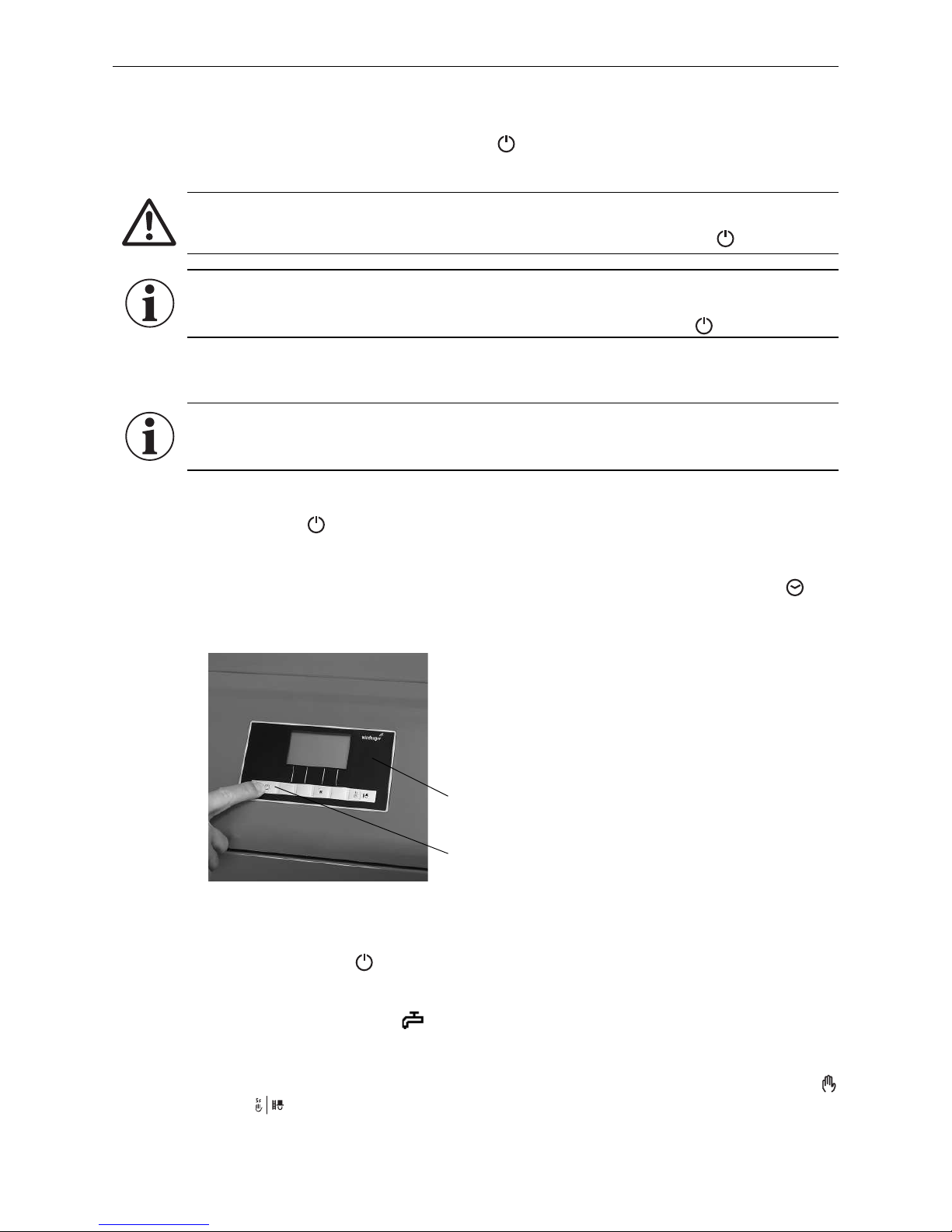
1. Press the ON/OFF button on the InfoWIN
PLUS
panel to turn on the lighting and display. The signal lamp
will turn green and a self-test will be performed at this time. After a successful self-test (and if a setpoint is
communicated by the external system control), the boiler automatically starts operation.
2. Set the operating mode switch(es) on the MESplus control module(s) to “Automatic operation”
.
The
system is operated (
e.g., setting temperatures and operating times) using the user module (installed in the
living area) – for more details, please refer to the instructions.
Turning off heating system:
Set the operating mode to “Standby” using the user module (installed in the living area).
Summer mode, hot water only:
Set the operating mode to „DHW operation“ using the user module (installed in the living area).
Emergency operation:
In the event of a system control failure, select the “Manual operation” mode using the MES control module
and InfoWIN
PLUS
unit (see Manual operation InfoWIN
PLUS
) to activate emergency operation and maintain
heat and hot water.
Fig. 23
ON/OFF button
InfoWIN
PLUS
operating unit
Page 20
20
3. Care, Cleaning, and Maintenance
3. Care, Cleaning, and Maintenance
A clean boiler saves fuel and protects the environment. Therefore, always clean your boiler as required when the
cleaning and ash removal request is displayed ( e.g., after specified cleaning intervals for the wood gasificiation
boiler).
3.1 Care of cladding and keyboard foil
Clean the boiler cladding and keyboard foil with a moist cloth, as needed. In the event of heavy soiling, use soapy
water or diluted suds (do not use strong cleaners or sharp cleaning instruments).
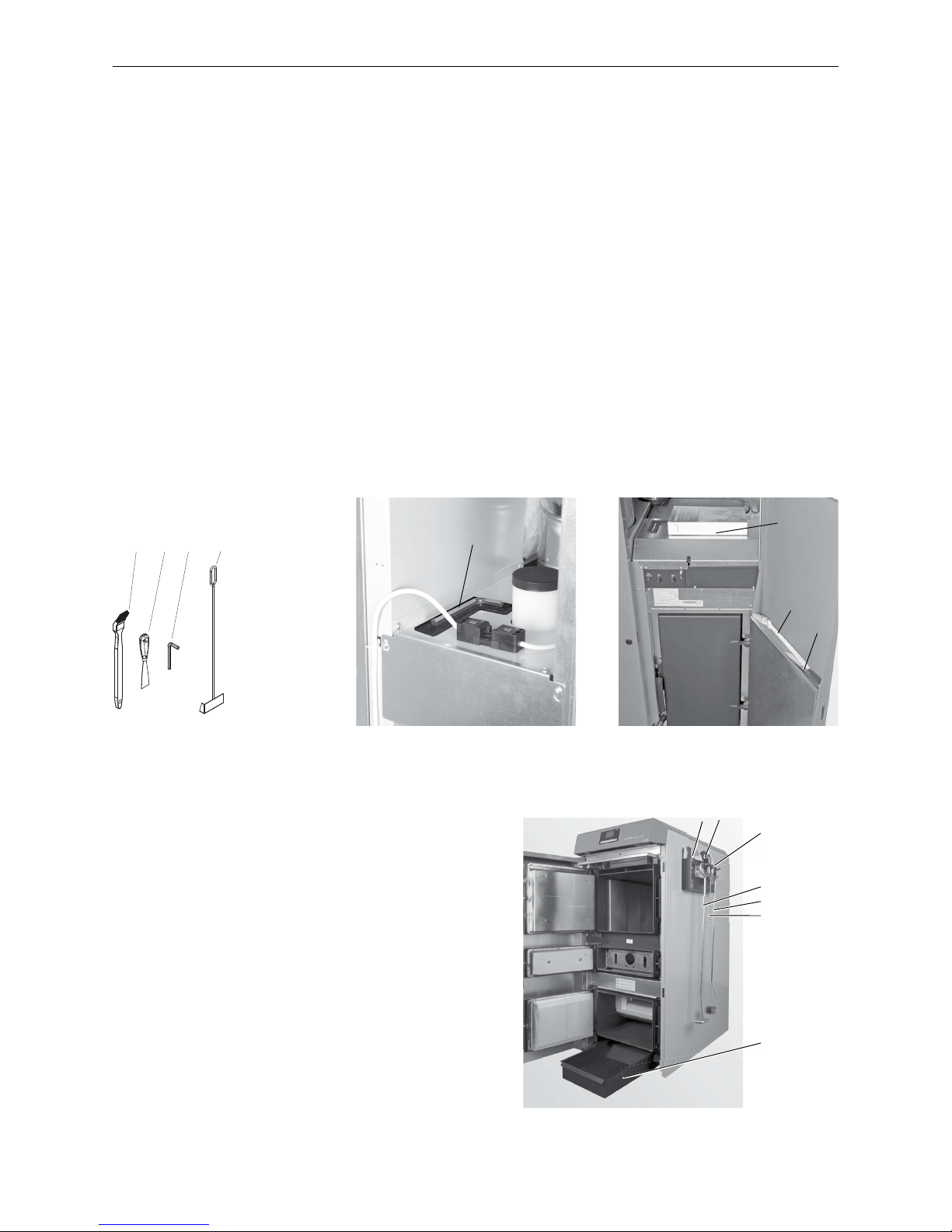
3.2 Cleaning and operating implements
Pellet boiler:
1 ........... Cleaning brush
2 ........... Spatula
3 ........... Allen key
4 ........... Scratcher (Pellet boiler)
5 ........... Folders containing instructions
1 2 3 4 5
Fig. 24 Cleaning and operating imple-
ments
Wood gasification boiler:
Supplied as standard:
5 ........... Instructions
6 ........... Scratcher (Wood gasification boiler)
7 ........... Ash pan
Optional accessory: cleaning kit EWK 020:
2 ........... Spatula
8 ........... Poker
9 ........... Cleaning brush
10 ........ Hanger (for installation on the wall or boiler side panel)
Fig. 25 Allen key
3
Fig. 26 Cleaning brush and spatula on in-
side of cladding door
1
2
5
Fig. 27 Ash pan under boiler
10
6
8
9
7
5 2
Page 21
21
3. Care, Cleaning, and Maintenance
3.3 Cleaning the wood gasification boiler
Information!
The specified cleaning intervals are for guidance only! The cleaning intervals vary depending on
the quality of the fuel, the nature of operation and the different operating phases (e.g. a lot of partial load, the blower spending a lot of time stationary during operations).
3.3.1 During each fill:
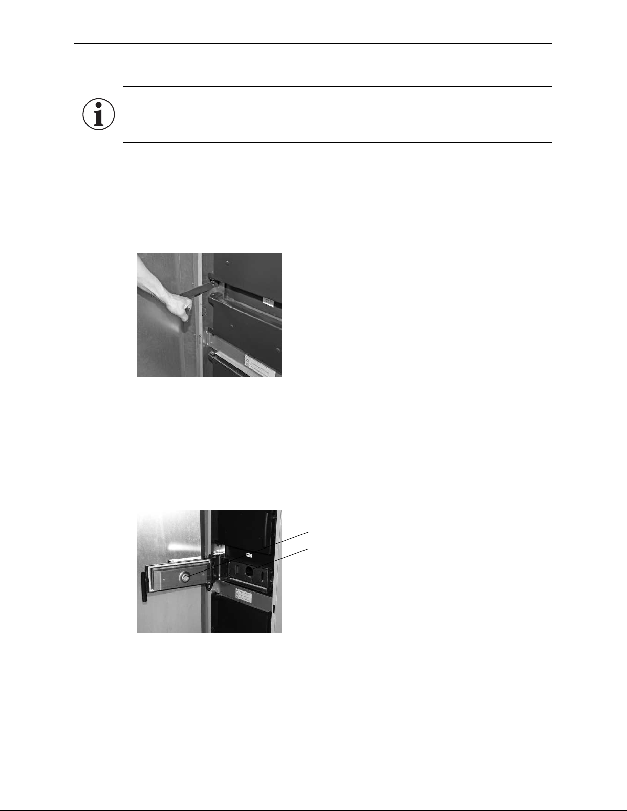
3.3.1.1 Lever for cleaning heating surfaces
– Press lever for cleaning heating surfaces 5–10 times – Fig. 28.
3.3.1.2 Ignition openings on lighting door1 and vertical grate
Check ignition openings on lighting door and vertical grate; clear if necessary – Fig. 29.
1
Only for wood gasification boiler with automatic ignition
Fig. 28 Pressing lever for cleaning heating
surfaces 5–10 times
Fig. 29 Checking ignition openings
Ignition opening on lighting door
Ignition opening on vertical grate
Page 22
22
3. Care, Cleaning, and Maintenance
3.3.2 Weekly
3.3.2.1 Removing ash
Recommended cleaning implement: Scraper
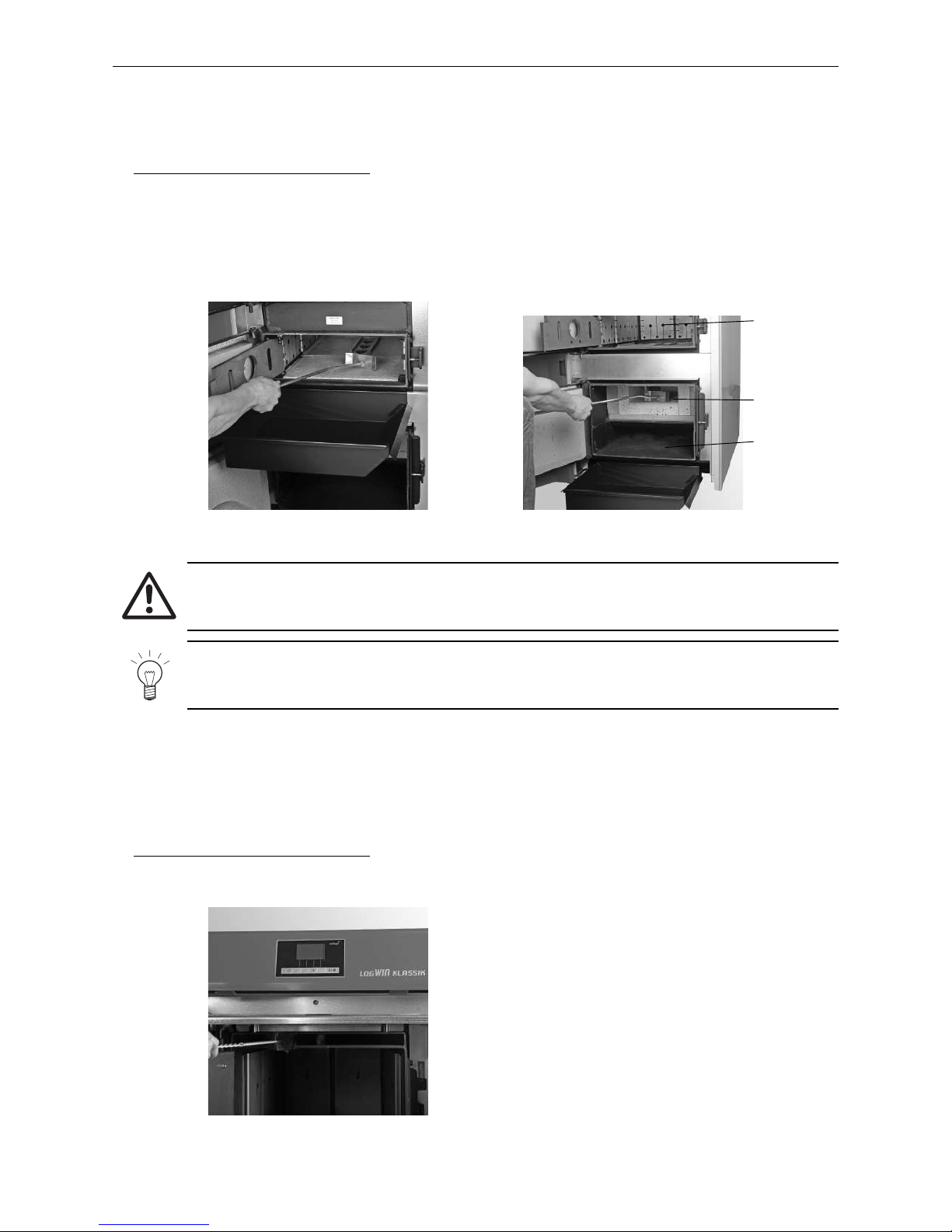
– Attach ash pan at height of lighting door (central door) in the intended hook-in plate – Fig. 30.
Open lighting door and vertical grate, and sweep most of the remaining ash into the ash pan.
– Place ash pan under ash door (bottom door). Open ash door and carefully remove the accumulated ash out of
the combustion and ash chambers – Fig. 31.
Fig. 30 Attaching ash pan, removing ash Fig. 31 Removing ash from combustion
chamber and ash chamber
Holes in the
hook-in plates
Combustion
chamber
Ash chamber
3.3.3 Annually
3.3.3.1 Low temperature carbonisation gas duct:
Recommended cleaning implement: Cleaning brush and vacuum cleaner
– Clean duct for carbonisation gas extraction – Fig. 32.
Fig. 32 Cleaning carbonisation gas extraction
Attention!
Risk of fire if ash has not cooled! Store ash in lockable and non-combustible container on noncombustible base for at least 48 hours.
Note!
The ash may be loaded with heavy metals. Heavy metals may affect soil fertility. Ash is not therefore suitable as a fertiliser and should be disposed of with residual waste.
Page 23
23
3. Care, Cleaning, and Maintenance
3.3.3.2 Blower box, blower wheel
Attention!
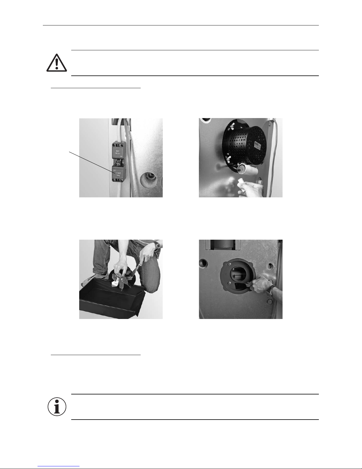
De-energise the boiler before cleaning the blower box and blower wheel! Disconnect power plug
– Fig.33.
Recommended cleaning implement: Spatula, brush, and vacuum cleaner
– Disconnect the blower plug – Fig. 33.
– Remove wing nut from blower box – Fig.34.
– Remove the blower unit and clean blower wheel – Fig. 35.
– Thoroughly clean the blower box interior – Fig. 36.
3.3.3.3 Exhaust pipe:
Recommended cleaning implement: Spatula, cleaning brush, soft cloth
– Clean the exhaust pipe leading to the flue through the cleaning opening provided in the exhaust pipe, or
through the blower box.
– Use soft cloth to clean exhaust sensor (accessory).
Information!
Be careful of the sensors in the flue outlet when cleaning the exhaust pipe - do not bend or damage
them. No warranty claims will be accepted for damage resulting from incorrect cleaning!
Fig. 33 Disconnecting plugs
Power plug
Fig. 34 Disconnect the blower plug and
Remove wing nut
Fig. 35 Cleaning blower wheel Fig. 36 Clean the interior of the blower box
Page 24
24
3. Care, Cleaning, and Maintenance
3.3.3.5 Draught limiter (swinging draught flap)
Recommended cleaning implement: Spatula
If a draught limiter is fitted (by customer) in the flue or exhaust pipe, check for ease of movement. If
necessary, clean or have it adjusted by a specialist.
3.3.3.6 Filling, lighting, and ash doors
Recommended cleaning implement: Spatula
– Open doors. The door seals must leave a clean imprint. Remove any crustations or deposits that could impair
the door seals and ease of movement.
If the door seals do not leave a clean imprint or are not sealed, adjust the doors and/or replace the seals.
– If the doors do not move freely, lubricate the bearings of the door hinges with heat-resistant paste ( e.g.,
graphite paste).
3.3.3.7 Thermocontrol sensor
Recommended cleaning implement: Brush, soft cloth
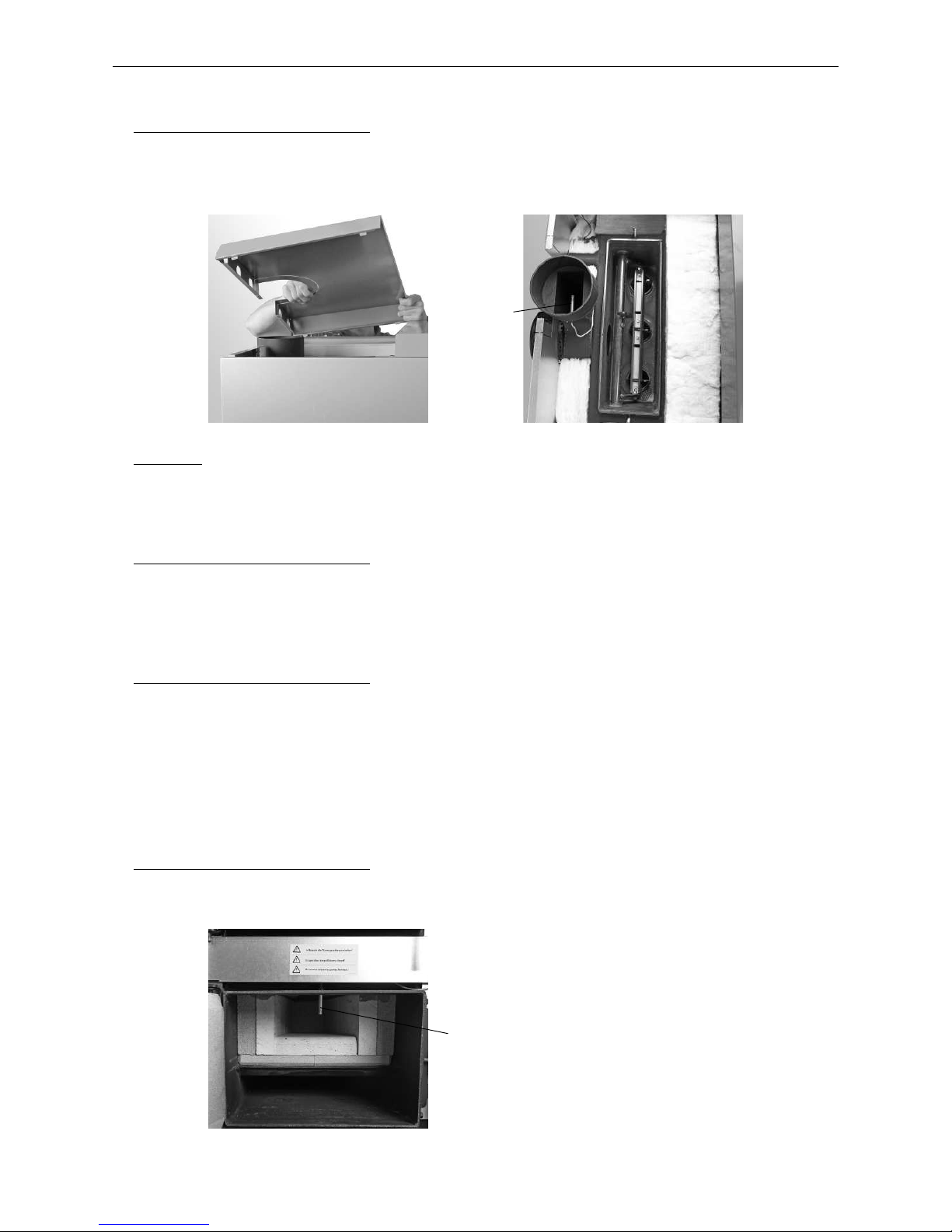
– Clean fly ash from the thermocontrol sensor with a brush or soft cloth – Fig. 39.
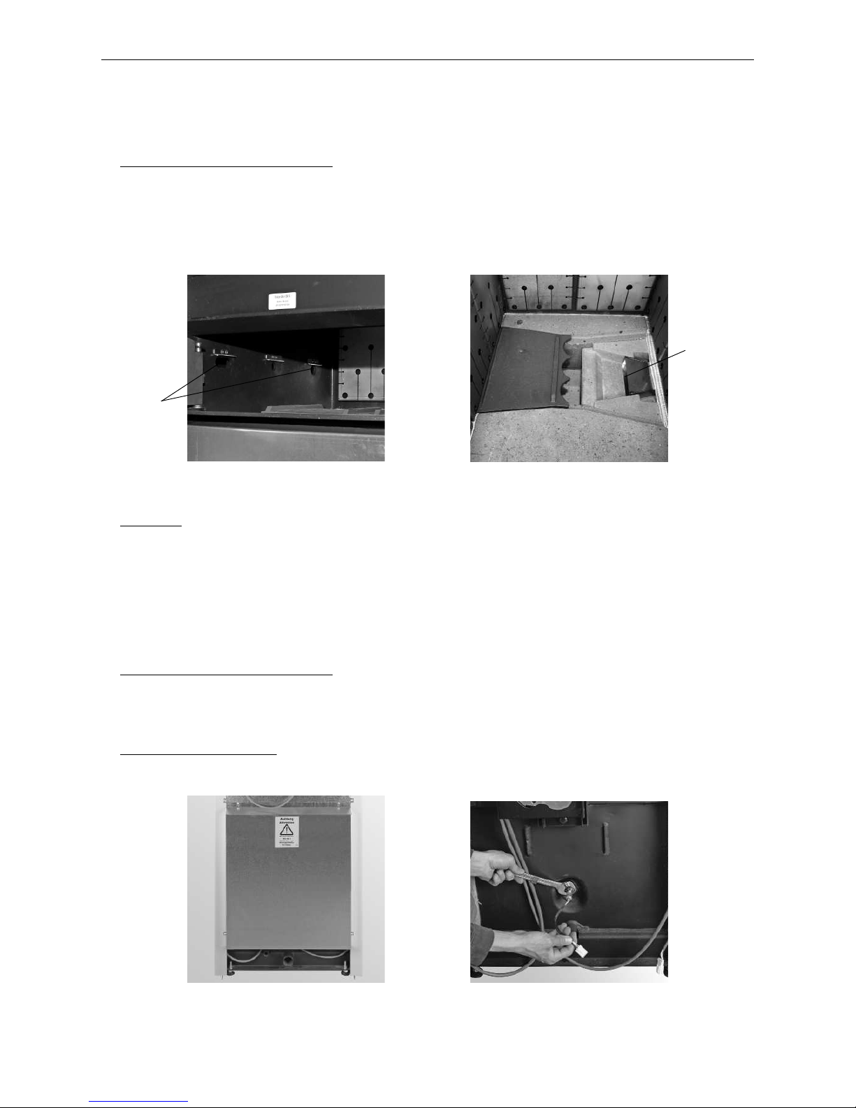
3.3.3.4 Upper coasting surfaces
Recommended cleaning implement: Spatula, brush, and vacuum cleaner
– Remove the rear boiler cover – Fig. 37.
– Remove the screw connections on the cleaning cover and remove the cover. Thoroughly clean the upper parts
of the coasting surface – Fig. 38.
Fig. 37 Removing the rear boiler cover Fig. 38 Cleaning the upper coasting surfaces
Fig. 39 Cleaning the thermocontrol sensor
Thermocontrol sensor
exhaust sensor
(accessory)
Assembly:
Complete these steps in reverse order.
Page 25
25
3. Care, Cleaning, and Maintenance
3.3.3.8 Primary and secondary air routes
These parts are also checked and cleaned during maintenance by Windhager customer service or the customer
service partner.
Recommended cleaning implement: Spatula, vacuum cleaner
– Remove hook-in plates from both sides of filling chamber and check the primary air openings underneath.
Clear if necessary – Fig. 40.
– Remove both burning plates and check the secondary air openings underneath. Clear if necessary – Fig. 41.
Fig. 40 Removing hook-in plate;
checking primary air openings.
Fig. 41 Taking out burning plates,
checking secondary air openings.
Secondary air
openings
Primary air
openings
3.3.3.9 Lambda sensor
These parts are also checked and cleaned during maintenance by Windhager customer service or the customer
service partner.
Recommended cleaning implement: Brush, soft cloth
– Remove the rear wall at the bottom – Fig. 42.
– Use an open-ended wrench (WAF 22) to disconnect and unscrew the lambda sensor (Fig. 43). Carefully
remove dirt with a brush or soft cloth.
Fitting the lambda sensor: Screw in the sensor by hand, and then use wrench to tighten about 1/4 of a turn.
Connect the probe. Screw on rear wall again.
Fig. 42 Unscrewing rear wall at bottom Fig. 43 Disconnecting and unscrewing the
lambda sensor
Assembly:
Complete these steps in reverse order.
Page 26

26
3. Care, Cleaning, and Maintenance
3.4 Cleaning the pellet boiler
3.4.1 Overview of intervals between cleaning (maintenance)
The pellet boiler is equipped with a cleaning and ash removal interval display. The “Stage 1 cleaning“ and “Stage
2 cleaning“ cleaning requests are displayed on the InfoWIN
PLUS
and must be reset after cleaning/ash removal is
completed – see section 3.4.6.
The cleaning and ash removal intervals may be reduced or extended depending on the pellets used (e.g. ash
proportion), the power consumed by the heating system (frequently switching on and off) and the boiler size of
the pellet boiler.
Annual maintenance is required in addition to cleaning. This is shown in the display as “Maintenance“ and is
performed by the Windhager customer service or customer services partner. It is a prerequisite for the warranty
conditions.
Pellet boiler
Display What needs to be done?
Stage 1 cleaning
“Stage 1 cleaning“
IN 520
or
“Emergency operati-
on!
Stage 1 cleaning“
FE 320
Empty the ash pan and remove ash from coasting surface
(see section 3.4.2)
Clean the thermocontrol sensor.
(see section 3.4.3.1)
Confirm stage 1 cleaning
(see section 3.4.7)
Stage 2 cleaning
“Stage 2 cleaning“
IN 521
or
“Emergency operati-
on!
Stage 2 cleaning“
FE 321
Empty the ash pan and remove ash from coasting surface
(see section 3.4.2
Clean combustion chamber and burner pot,
(see section 3.4.3)
Clean top coasting surfaces and blower wheel
(see section 3.4.4)
Vacuum out exhaust pipe to flue
(see section 3.5)
Water tank level
(see section 3.4.5)
Confirm stage 2 cleaning
(see section 3.4.7
Full service
“Full service“
IN 524 / FE 324
Have Windhager customer services or a customer services partner perform
maintenance within the next 3 months. This is a prerequisite for the warranty
conditions – see section 3.7.
At least once per
heating season
Cleaning supply container and feed unit flap (see section 3.4.6)
Pellet storage room or storage container (see section 3.6)
Page 27
27
3. Care, Cleaning, and Maintenance
3.4.2 Emptying ash pan; removing ash from underneath coasting surface
Attention!
Do not open the combustion chamber door during operation. Always turn off the boiler first with the
ON/OFF button and wait until burnout mode has finished.
Risk of fire if ash has not cooled! Store ash in lockable and non-combustible container on noncombustible base for at least 48 hours.
Note!
Small amounts of ash can be used in the garden as fertiliser. Larger amounts of ash should be
disposed of together with other residual waste (please observe the applicable regulations).
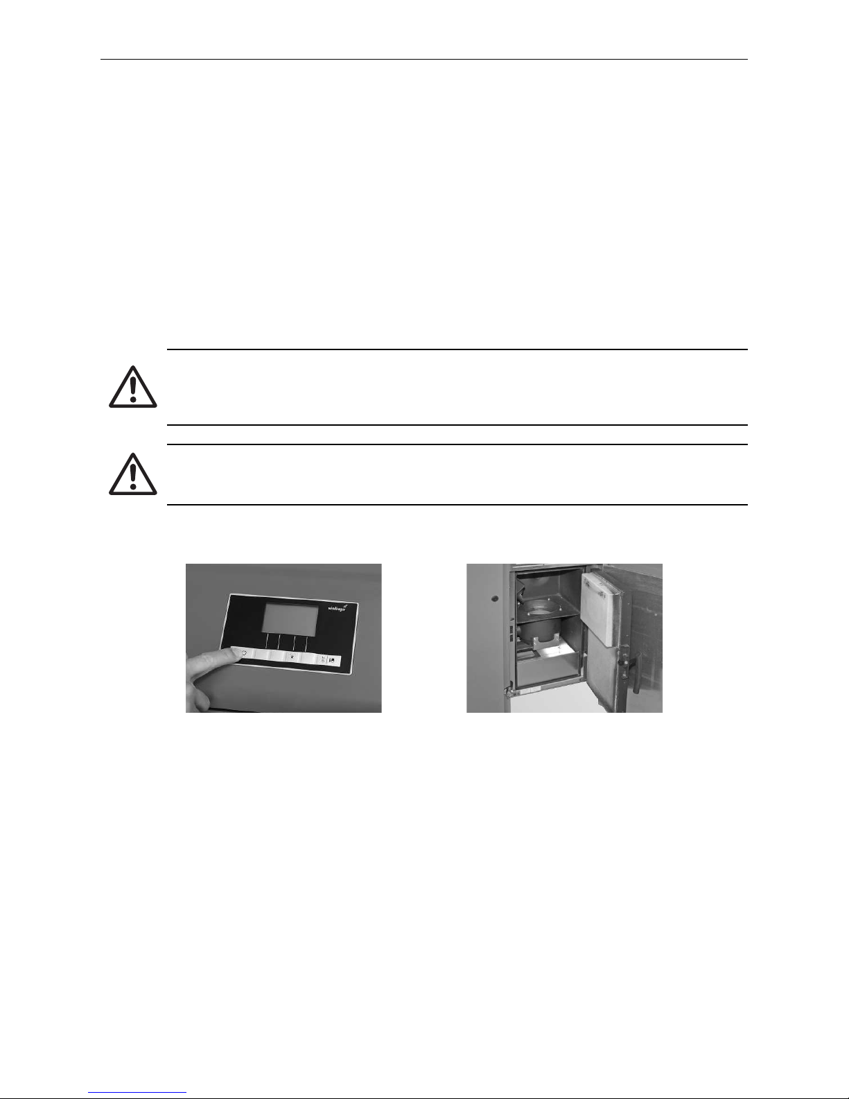
– Using the ON/OFF button on the InfoWIN
PLUS
, turn off the boiler (Fig. 44) and wait until the display has gone
out (ca. 20 min).
– Open cladding door and combustion chamber door – Fig. 45 – and section. 2.2.
– Remove the ash pan and place it in front of the boiler – Fig. 46.
– Turn the handle on the coasting surface cover in a clockwise direction and remove the cover – Fig. 47.
Fig. 44 Turning off boiler Fig. 45 Open cladding door and
combustion chamber door
Fig. 46 Remove the ash pan and place it
in front of the boiler
Fig. 47 Turn handle and remove cover
Fig. 48 Remove ash from coasting surface
into ash pan
– Use the scraper to remove ash from underneath the coasting surface and into the ash pan – Fig. 48.
Page 28
28
3. Care, Cleaning, and Maintenance
Assembly:
– Remove all ash. The coasting surface cover should fit/seal tightly.
– Position the coasting surface cover and turn the handle as far as possible in a clockwise direction.
– Push the ash pan into place.
– Close the combustion chamber door and cladding door and turn the boiler back on with the ON/OFF button.
– Confirm cleaning request once “Cleaning“ has finished – see section. 3.4.7.
3.4.3 Cleaning the combustion chamber and burner pot
Attention!
Do not open the combustion chamber door during operation. Always turn the boiler off first with
the ON/OFF button and wait until burnout mode has finished – Fig. 49. It is essential to let the combustion chamber cool down before cleaning.
Attention!
Before cleaning with a vacuum cleaner, ensure that any embers in the combustion residue are fully
extinguished!
– Open cladding door and combustion chamber door – Fig. 50 – see section 2.2.
Fig. 49 Turning off boiler Fig. 50 Open cladding door and combustion
chamber door
Page 29
29
3. Care, Cleaning, and Maintenance
3.4.3.1 Cleaning the thermocontrol sensor and down chute
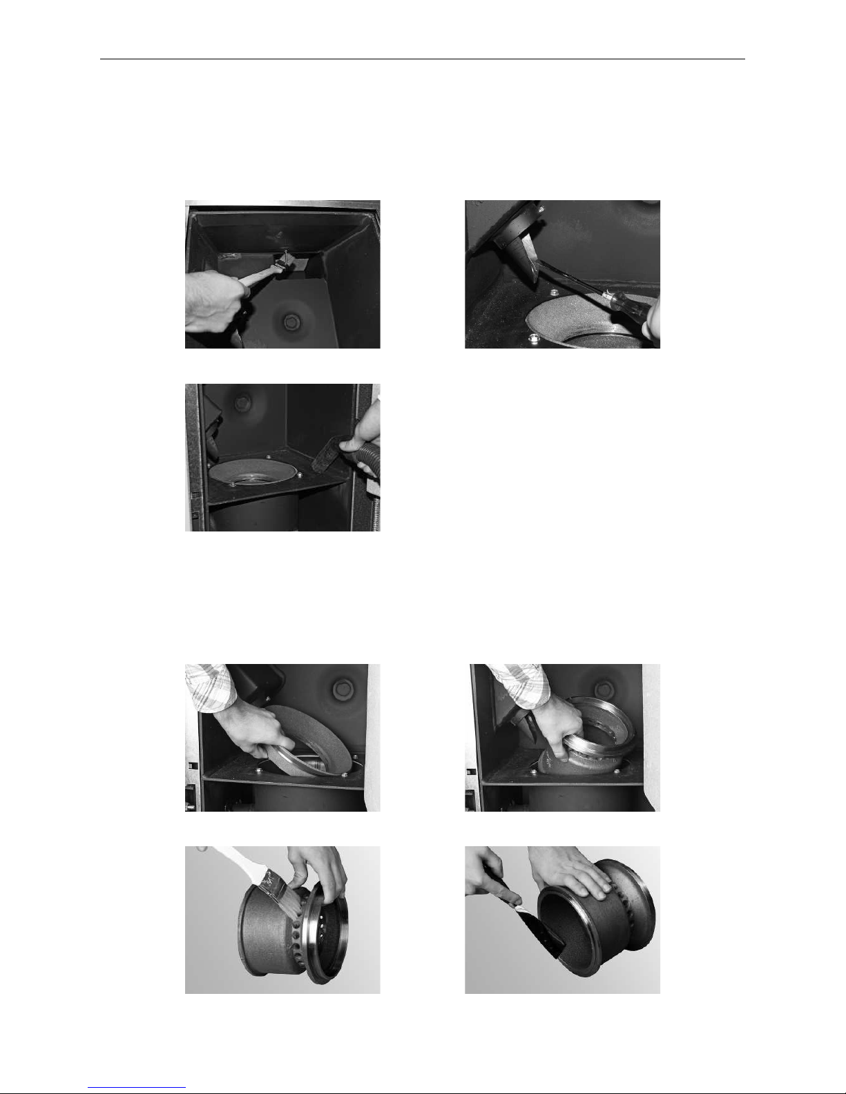
– If necessary, remove fly ash from the thermocontrol sensor. The thermocontrol sensor is located in the com-
bustion chamber – Fig. 51.
– If necessary, use screwdriver to clean inside of down chute – Fig. 52.
– Remove combustion residue from the combustion chamber with a vacuum cleaner – Fig. 53.
Fig. 51 Cleaning the thermocontrol sensor Fig. 52 Cleaning the down chute
Fig. 53 Remove residue from combustion
from the combustion chamber
3.4.3.2 Burner pot cleaning
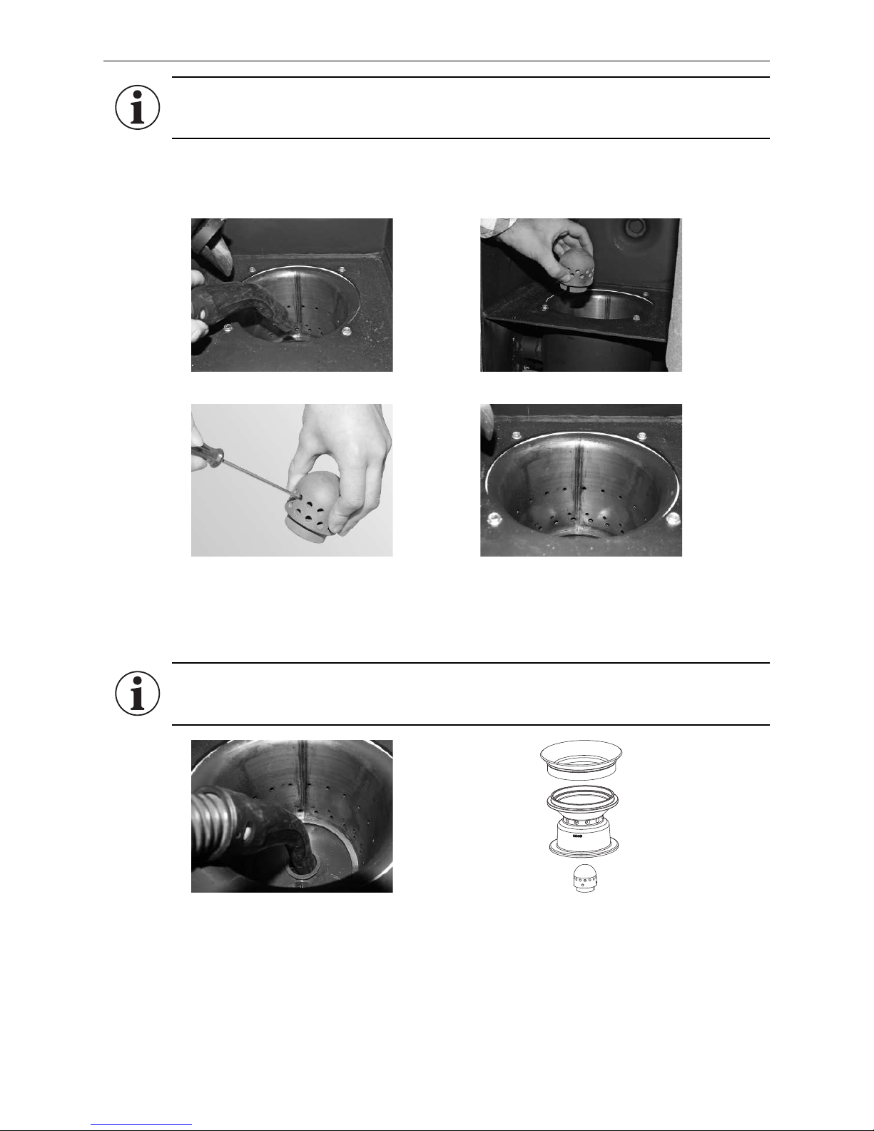
– Lift the bottom and top part of the cone out of the burner pot – Fig. 54, 55.
– Remove all traces of sediment accumulation from the cones with a brush or scrape off with the spatula –
Fig.56, 57.
Fig. 54 Lift out top part of cone Fig. 55 Lift out bottom part of cone
Fig. 56 Clean cone Fig. 57 Clean cone
Page 30
30
3. Care, Cleaning, and Maintenance
– Vacuum out the burner pot (Fig. 58), remove the primary air pin and carefully clean the holes with a small
screwdriver or drill bit if necessary (holes must be clear) – Fig 59, 60.
– All secondary air holes in the burner pot must be kept clear – Fig. 61.
Fig. 58 Vacuum out the burner pot Fig. 59 Take out the primary air pin
Fig. 60 Clean the primary air pin carefully Fig. 61 Clean the secondary air holes in
the burner pot carefully
Information!
When cleaning the boiler, always first remove all the ash from the combustion chamber. Do not
remove the primary air pin for cleaning until afterwards.
– Use a vacuum cleaner to vacuum combustion residues out of the burner pot. Vacuum the ash out of the pri-
mary air tube (in the middle of the burner pot) – Fig. 62.
Information!
Before inserting the primary air pin , once again vacuum out the primary air tube in the middle of
the burner pot. Make sure there is no debris in the tube (damage to the ignition element!).
Assembly:
– By working through these steps in reverse order – Fig. 63.
– Confirm cleaning request once “Cleaning“ has been finished – see section 3.4.7.
Fig. 62 Vacuum out the primary air tube in
the centre of the burner pot
Fig. 63 Bottom and top part of the cone,
primary air pin
Page 31
31
3. Care, Cleaning, and Maintenance
3.4.4 Cleaning top coasting surfaces and blower wheel
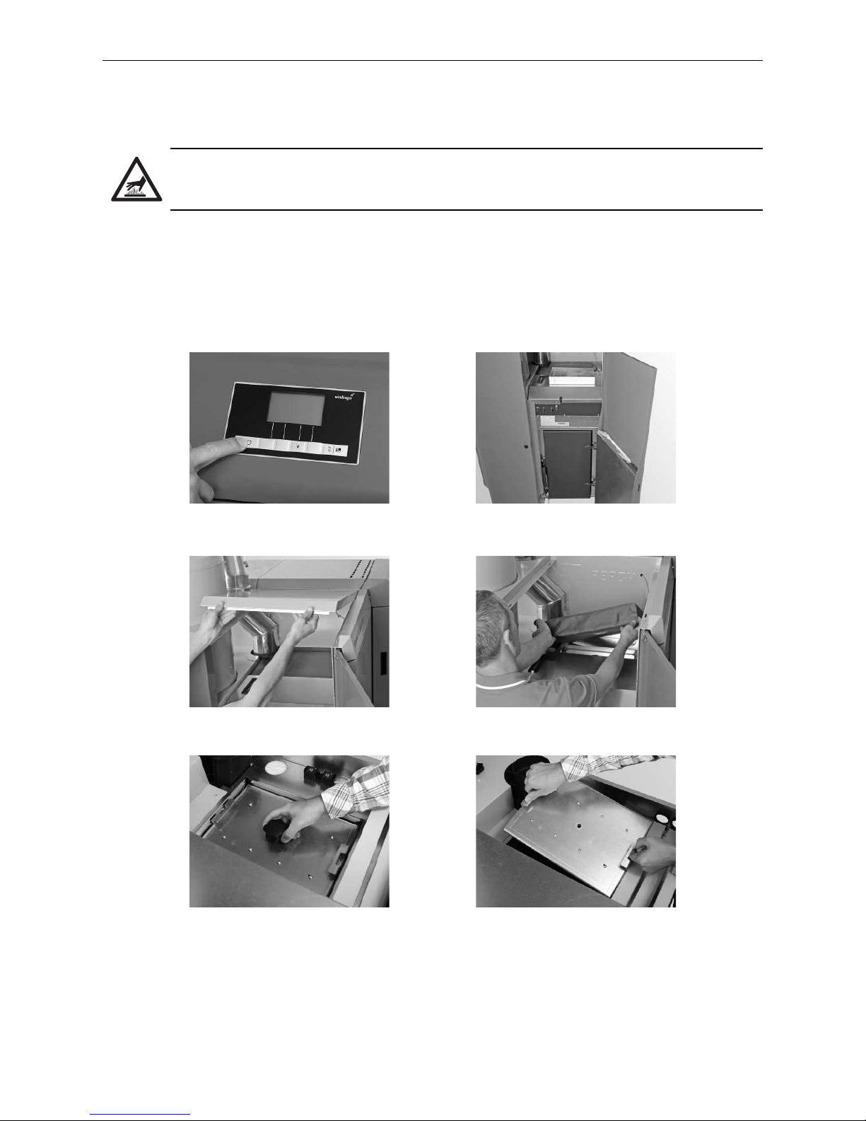
– Using the ON/OFF button on the InfoWIN
PLUS
, turn off the boiler (Fig. 64) and wait until the display has gone
out (ca. 20 min).
Warning of hot surface: risk of burns!
Before touching the screw connections and coasting surface cover, turn off the boiler and let it
cool.
– Open the cladding door (Fig. 65) – refer also to section 2.2.
– Pull the cover on the pellet boiler side towards you and lift it off – Fig. 66.
– Remove insulation from the coasting surfaces cover – Fig. 67.
– Unscrew and remove the screws on the cover – Fig. 68, 65.9
Fig. 64 Turning off boiler Fig. 65 Opening the cladding door
Fig. 66 Pull the cover on the pellet boiler
side forwards and remove it
Fig. 67 Remove insulation
Fig. 68 Loosen the screws Fig. 69 Lift off the cover
Page 32
32
3. Care, Cleaning, and Maintenance
Assembly:
Complete these steps in reverse order.
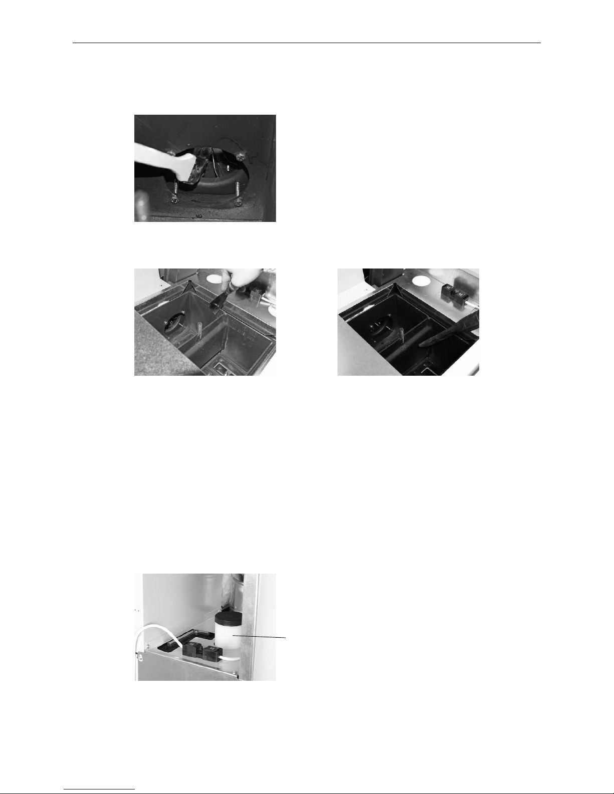
Fig. 70 Clean and vacuum the blower wheel
– Clean the blower wheel with a brush – Fig. 70.
– Clean the top of the coasting surfaces with a spatula and brush – Fig. 71.
– Vacuum out the ash from the coasting surfaces – Fig. 72.
Fig. 71 Clean the coasting surfaces Fig. 72 Vacuum out the ash
3.4.5 Water tank level
Check the water tank level approximately every 2 weeks and top up with water, if necessary (approx. 8 litres).
Water level must not fall below the minimum mark.
– Remove plug from water tank and top up – Fig. 73.
– Confirm cleaning request once “Stage 2 cleaning“ has been completed – see section 3.4.7.
Water tank min. mark
Fig. 73 Filling water container
Page 33
33
3. Care, Cleaning, and Maintenance
3.4.6 Cleaning fuel hopper and feed unit flap
It is necessary to clean the integral fuel hopper and/or flap in the feed unit if too much dust has collected, or
foreign bodies are in the integral fuel hopper.
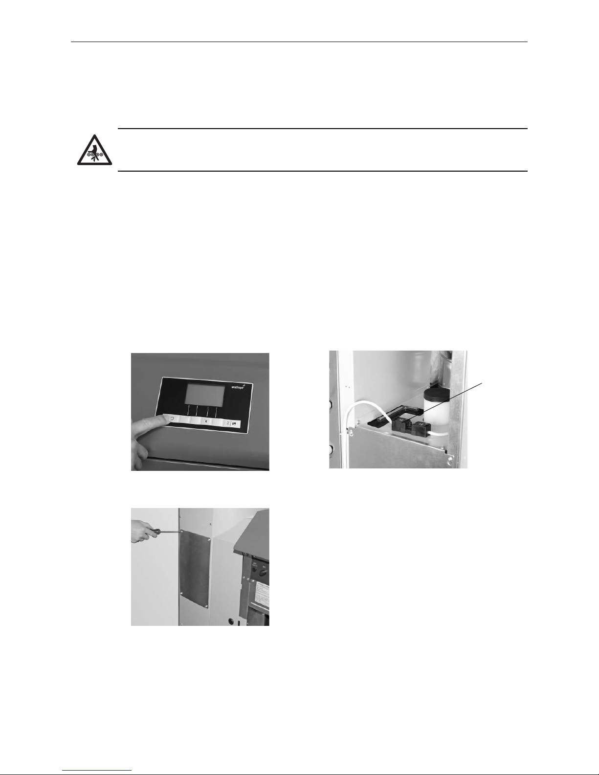
– Using the ON/OFF button on the InfoWIN
PLUS
, turn off the boiler (Fig. 74) and wait until the display has gone
out (ca. 20 min).
Please note! Crush risk from rotating auger.
Before opening the inspection cover, always disconnect the boiler from the power supply.
Disconnect the mains power plug.
– Disconnect the mains power plug – Fig. 75.
– Place a container for the pellets at the front.
– Remove the cladding from the integral fuel hopper (see assembly instructions).
– Remove the screws from and carefully raise the inspection cover. Pellets may gush out depending on how
many are present– Fig. 76.
Emergency refill the fuel hopper:
– Remove pellets and dust from fuel hopper.
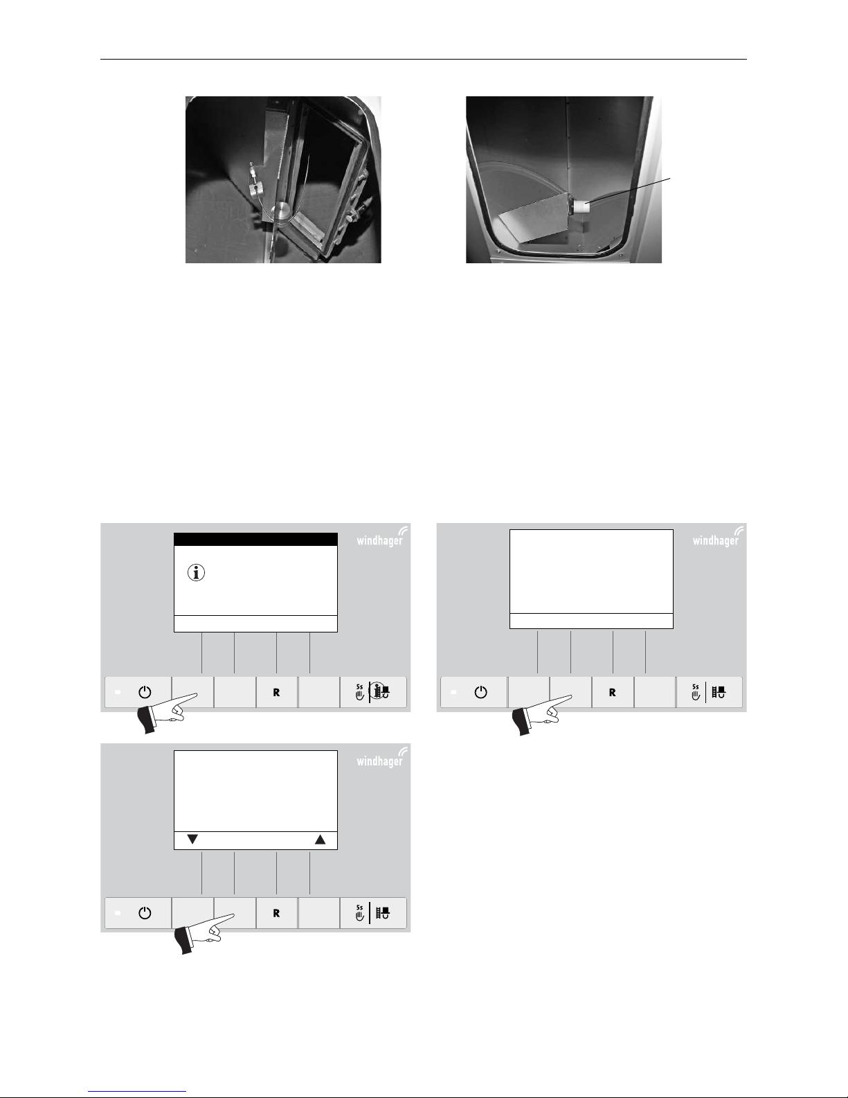
– Remove dust from the feed flap and proximity switch (Fig. 77, 78) and check that flap opens and closes
smoothly. It must make full contact with the seal..
Fig. 74 Turning off boiler
Fig. 75 Disconnecting mains power plug
Mains power
plug
Fig. 76 Remove the screws and take off
the inspections cover
Page 34
34
3. Care, Cleaning, and Maintenance
Assembly:
Complete these steps in reverse order.
Fig. 77 Feed unit flap
Proximity switch
with telltale
Fig. 78 Proximity switch feed unit
Fig. 79 Fig. 80
Empty the ash pan, remove ash
from heat exchanger base.
Clean thermocontrol sensor.
Follow operating manual.
Push “next“ to confirm
stage 1 cleaning.
Next back
3.4.7 Confirm stage 1 cleaning or Confirm stage 2 cleaning Reset cleaning request
Fig. 81
Was stage 1 cleaning performed
according to the instructions?
Confirm
Yes back
BioWIN-II
Stage 1 cleaning
IN 520
(Operating phases)
Info Reset Menu
42
°C
Page 35
35
3. Care, Cleaning, and Maintenance
3.5 Exhaust pipe to flue
Clean/vacuum out the exhaust pipe (pipe connecting the boiler and flue) around the cleaning aperture.
Information!
Be careful of the sensors in the flue outlet when cleaning the exhaust pipe - do not bend or damage
them. No warranty claims will be accepted for damage resulting from incorrect cleaning!
3.6 Pellet storage room or storage container
Attention!
Please also note the hazard information in section 1.3.3. ”Entering the pellet storage room/storage
container.” Do not attempt to enter an unventilated storage room (particularly buried tanks).
Information!
When entering the pellet storage room or storage container, do not stand on the pellets surrounding the suction probe.
Before filling the pellet storage room or storage container, check the following:
– whether the storage room is free of foreign bodies.
– whether a lot of dust has settled on the floor over time.
Please note: A layer of dust on top of the pellets is normal because dust present migrates to the surface when
the pellets gush out during removal.
– whether pellets have swelled up against the wall if the storage room is not fully dry.
Tip!
Leading pellet suppliers recommend fully emptying the storage room every 2–3 yearsto ensure
that there is sufficient turnover of pellets (so old pellets do not remain in the hopper). Automatic
changeover between the three suction probes can be deactivated using the InfoWIN
PLUS
(see Manual operation InfoWINPLUS). This allows you to fully empty the storage room for one probe. You
can then continue heating with the other suction probes. If you perform this task every year with a
different probe, you will “replace” your entire supply of pellets regularly.
Page 36
36
3. Care, Cleaning, and Maintenance
3.7 Full service
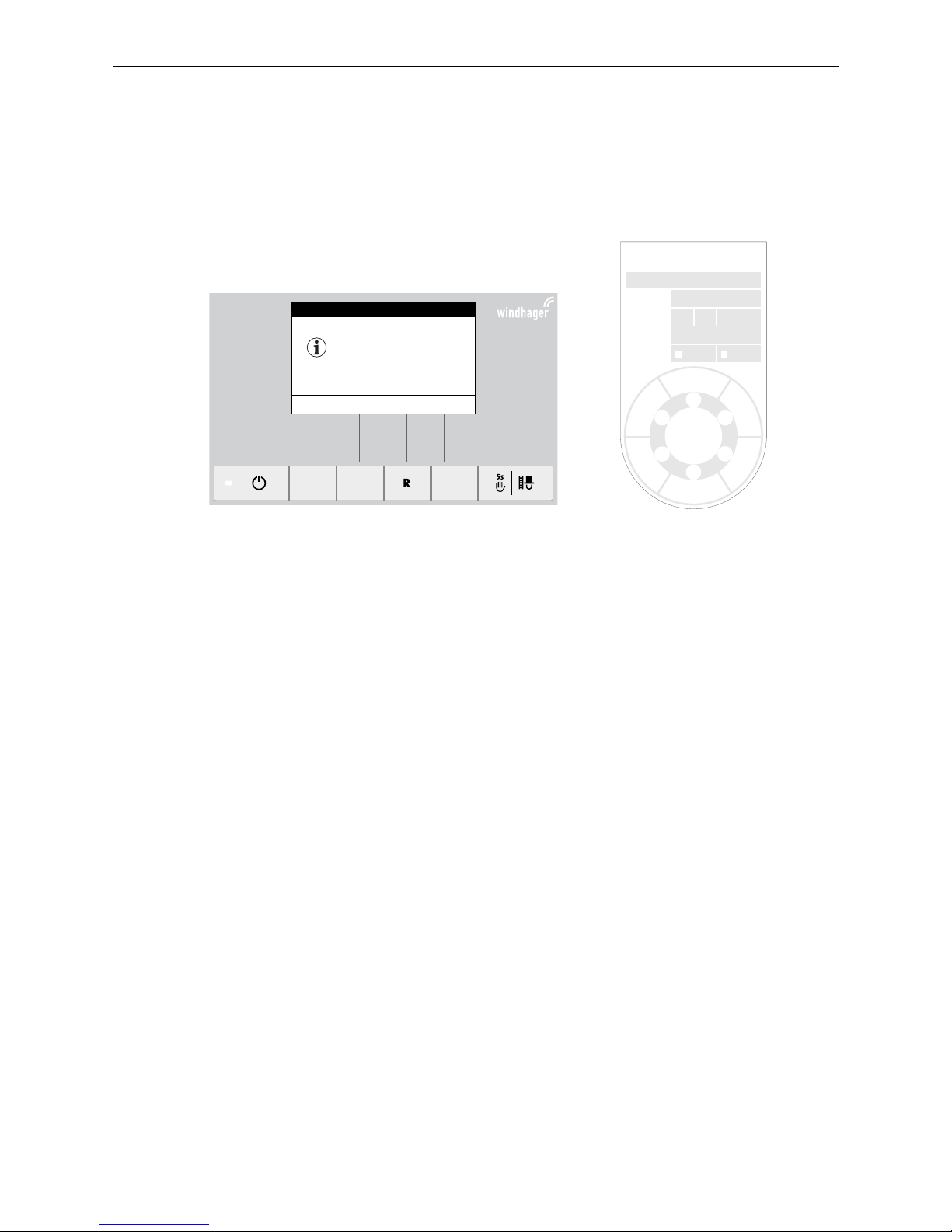
Annual maintenance is required in addition to cleaning, and must be performed by Windhager customer service
or a customer services partner. It is a prerequisite of the guarantee limitations and must be completed at latest
by the date on the inspection plate Fig. 83.
Fig. 82
Prüfplakette WARTUNG
Kundennummer / Kesseltype
Prüfer
Prüfdatum
für Prüfjahr
2
0
1
7
Prüfturnus
1 Jahr 2 Jahre
Nächste
Prüfung
2
0
1
4
2
0
1
5
2
0
1
6
2
0
1
8
2
0
1
9
20
20
024140-00
Fig. 83 Inspection plate for maintenance
BioWIN-II
Full service
IN 524
(Operating phases)
Info Reset Menu
42
°C
Page 37

37
4. Emissions Measurement - Wood Gasification Boiler
4. Emissions Measurement - Wood Gasification
Boiler
4.1 Preparation
- Complete boiler cleaning - see section 3.3.
– After boiler cleaning, let 4 or 5 burning cycles run before measuring the exhaust gas.
- Prepare the fuel – see section 1.4.2.
– Ensure there is sufficient heat consumption: • The buffer tank is not allowed to be heated up.
• Mixer and radiator valves must be fully opened.
• Set the controller to heating mode (sun).
4.3 Measurement
– Begin at least 5 minutes after placing the fuel on a well formed basic firebed.
– Start the chimney sweeper function by pressing the chimney sweeper button (see operating manual InfoWIN-
PLUS
). The boiler water temperature must be at least 60°C at the start of the measurement, and may not exceed 75°C during the measurement. Otherwise, check the heat consumption = open boiler and mixer valves,
etc. The flue draught should be between 0.10 and 0.20 mbar.
– Duration of measurement: 15 minutes
Tip!
Use pieces of softwood (max. 50 cm long) and place them split surface downwards – this will establish
the necessary basic firebed sooner. Fill the filling chamber no more than half full – otherwise the
burning time will be too long.
– Prepare the embers.
There must be sufficient embers to reach the top row of primary air openings in the hook-in plates. This
requires heating for at least one hour after ignition. Thoroughly poke the embers: make sure there are no cavities
in the fire (through the lighting door/vertical grate, push the embers and fuel wood together compactly).
4.2 Heating
– Ignite – see section 2.6.
Page 38

38
5. EG-Declaration of Conformity
5. EG-Declaration of Conformity
5.1 Wood gasification boiler
for the LogWIN range of wood gasification boilers
(Machinery Directive 2006/42/EC, Appendix II A)
Issued by: WINDHAGER ZENTRALHEIZUNG Technik GmbH
Anton-Windhager-Straße 20
A-5201 Seekirchen
Name and address of the person authorised to compile the technical documentation:
DI Richard Reiter
Anton-Windhager-Straße 20
A-5201 Seekirchen
Subject of the declaration: LogWIN range of wood gasification boilers
The units conform to the relevant requirements of the Machinery Directive (2006/42/EC) and the EMC Directive
(2004/108/EC).
In addition, we declare that we have applied the following technical standards:
EN 303-5: 2012-10 EN 60335-1: 2012-10
EN 61000-6-2: 2005 EN 61000-6-3: 2007 A1:2011
Seekirchen, 4. 3. 2014 WINDHAGER ZENTRALHEIZUNG Technik GmbH
Richard Reiter, Development - Solid Fuel Herbert Oitner, Board of Directors
Page 39

39
5. EG-Declaration of Conformity
5.2 Pellet boiler
for the BioWIN 2 pellet boiler series
(Machinery Directive 2006/42/EC, Appendix II A)
Issued by: WINDHAGER ZENTRALHEIZUNG Technik GmbH
Anton-Windhager-Straße 20
A-5201 Seekirchen
Name and address of the person authorised to compile the technical documentation:
Ing. Martin Klinger
Anton-Windhager-Straße 20
A-5201 Seekirchen
Subject of the declaration: Pellet boiler series BioWIN 2
The units conform to the relevant requirements of the Machinery Directive (2006/42/EC) and the EMC Directive
(2004/108/EC).
In addition, we declare that we have applied the following technical standards:
EN 303-5: 2012-10 EN 60335-1: 2012-10
EN 61000-6-2: 2005 EN 61000-6-3: 2007 + A1 : 2011
Seekirchen, 16. 6. 2014
WINDHAGER ZENTRALHEIZUNG Technik GmbH WINDHAGER ZENTR ALHEIZUNG Technik GmbH
Martin Klinger, Development - Pellets Herbert Oitner, Board of Directors
Page 40

Austria
Windhager Zentralheizung GmbH
Anton-Windhager-Straße 20
A-5201 Seekirchen bei Salzburg
T. +43 (0) 62 12/23 41-0
F. +43 (0) 62 12/42 28
Germany
Windhager Zentralheizung GmbH
Deutzring 2
D-86405 Meitingen bei Augsburg
T. +49 (0) 82 71/80 56-0
F. +49 (0) 82 71/80 56-30
Switzerland
Windhager Zentralheizung Schweiz AG
Industriestrasse 13
CH-6203 Sempach-Station bei Luzern
T. +41 (0) 41/469 469-0
F. +41 (0) 41/469 469-9
France
Windhager Chauffage Central
France S.A.S.
1, rue du Maire Georges Baruch
Z.A.C. Nord du Rosenmeer
F-67560 Rosheim
T. +33 (0)3 8881 8217
F. +33 (0)3 8895 8185
WARRANTY
The warranty requires that the boiler and related accessories be properly
installed and started by Windhager customer service or a customer service
partner; otherwise the manufacturer’s warranty will not be honoured. Malfunctions
resulting from improper operation or adjustment, as well as use of poor or not
recommended fuel types, are not covered by the warranty. Further, the warranty
shall be void if equipment other than that provided by Windhager is installed.
The special warranty restrictions for your system are available in the “Warranty
Conditions” folder supplied with your boiler.
Commissioning and regular maintenance following the terms of the “Warranty
Conditions” will assure safe, environmentally friendly, and economical operation of
your system. We recommend that you obtain a maintenance service contract.
We reserve the right to technical modifications, layout and printing errors, and
translation errors.
Subject to technical modifications. AWP-vor- übersetzt aus 024194/01
 Loading...