

Page 1
WOOD PELLETS
Installation Instructions
BioWIN XL
FOR USE IN CANADA / USA
03/2015 094886/01
Pellet central heating boiler/furnace
/
USA
2015 0948
86/
SAVE THESE INSTRUCTIONS
Page 2

2
Table of contents
Table of contents
1. Important Information for the Technician . . . . . . . . . . . . . . . . . . . . . . . . . . . . . . . . . . . . . . . . 4
1.1 Safety precautions . . . . . . . . . . . . . . . . . . . . . . . . . . . . . . . . . . . . . . . . . . . . . . . . . . . . . . . . . . . . . . . . . . . . . .4
1.1.1 Important information before you begin . . . . . . . . . . . . . . . . . . . . . . . . . . . . . . . . . . . . . . . . . . . . . . . . . . . . . . . . . 4
1.1.2 Caution symbols . . . . . . . . . . . . . . . . . . . . . . . . . . . . . . . . . . . . . . . . . . . . . . . . . . . . . . . . . . . . . . . . . . . . . . . . . . . . 4
1.1.3 Liability exclusion . . . . . . . . . . . . . . . . . . . . . . . . . . . . . . . . . . . . . . . . . . . . . . . . . . . . . . . . . . . . . . . . . . . . . . . . . . . 5
1.1.4 Safety instructions . . . . . . . . . . . . . . . . . . . . . . . . . . . . . . . . . . . . . . . . . . . . . . . . . . . . . . . . . . . . . . . . . . . . . . . . . . 5
1.2 Flue . . . . . . . . . . . . . . . . . . . . . . . . . . . . . . . . . . . . . . . . . . . . . . . . . . . . . . . . . . . . . . . . . . . . . . . . . . . . . . . . .10
1.3 Boiler room/Installation room . . . . . . . . . . . . . . . . . . . . . . . . . . . . . . . . . . . . . . . . . . . . . . . . . . . . . . . . . . .10
1.4 Fuel storage . . . . . . . . . . . . . . . . . . . . . . . . . . . . . . . . . . . . . . . . . . . . . . . . . . . . . . . . . . . . . . . . . . . . . . . . . .11
2. For the Installer . . . . . . . . . . . . . . . . . . . . . . . . . . . . . . . . . . . . . . . . . . . . . . . . . . . . . . . . . . . . 12
2.1 Scope of delivery, packaging . . . . . . . . . . . . . . . . . . . . . . . . . . . . . . . . . . . . . . . . . . . . . . . . . . . . . . . . . . . . .12
2.1.1 Boiler . . . . . . . . . . . . . . . . . . . . . . . . . . . . . . . . . . . . . . . . . . . . . . . . . . . . . . . . . . . . . . . . . . . . . . . . . . . . . . . . . . . . 12
2.1.2 Optional accessories . . . . . . . . . . . . . . . . . . . . . . . . . . . . . . . . . . . . . . . . . . . . . . . . . . . . . . . . . . . . . . . . . . . . . . . 12
2.2 Minimum clearances . . . . . . . . . . . . . . . . . . . . . . . . . . . . . . . . . . . . . . . . . . . . . . . . . . . . . . . . . . . . . . . . . . .12
2.3 System . . . . . . . . . . . . . . . . . . . . . . . . . . . . . . . . . . . . . . . . . . . . . . . . . . . . . . . . . . . . . . . . . . . . . . . . . . . . . . .13
2.3.1 Standards . . . . . . . . . . . . . . . . . . . . . . . . . . . . . . . . . . . . . . . . . . . . . . . . . . . . . . . . . . . . . . . . . . . . . . . . . . . . . . . . 13
2.3.2 Operation with external control and buffer only . . . . . . . . . . . . . . . . . . . . . . . . . . . . . . . . . . . . . . . . . . . . . . . . . . 13
2.3.3 Heating water . . . . . . . . . . . . . . . . . . . . . . . . . . . . . . . . . . . . . . . . . . . . . . . . . . . . . . . . . . . . . . . . . . . . . . . . . . . . . 13
2.3.4 Water-side resistance (pressure loss) . . . . . . . . . . . . . . . . . . . . . . . . . . . . . . . . . . . . . . . . . . . . . . . . . . . . . . . . . 15
2.4 Combustion air . . . . . . . . . . . . . . . . . . . . . . . . . . . . . . . . . . . . . . . . . . . . . . . . . . . . . . . . . . . . . . . . . . . . . . . . 16
2.4.1 Operating with room air . . . . . . . . . . . . . . . . . . . . . . . . . . . . . . . . . . . . . . . . . . . . . . . . . . . . . . . . . . . . . . . . . . . . . 16
2.4.2 Operating independently of the room air . . . . . . . . . . . . . . . . . . . . . . . . . . . . . . . . . . . . . . . . . . . . . . . . . . . . . . . 16
2.5 Installation sequence . . . . . . . . . . . . . . . . . . . . . . . . . . . . . . . . . . . . . . . . . . . . . . . . . . . . . . . . . . . . . . . . . . . 18
2.6 Setting up, preparing for installation . . . . . . . . . . . . . . . . . . . . . . . . . . . . . . . . . . . . . . . . . . . . . . . . . . . . . . 18
2.7 Installation. . . . . . . . . . . . . . . . . . . . . . . . . . . . . . . . . . . . . . . . . . . . . . . . . . . . . . . . . . . . . . . . . . . . . . . . . . . .19
2.8 Installing the exhaust pipe . . . . . . . . . . . . . . . . . . . . . . . . . . . . . . . . . . . . . . . . . . . . . . . . . . . . . . . . . . . . . .33
2.9 Installing the thermal discharge safeguard . . . . . . . . . . . . . . . . . . . . . . . . . . . . . . . . . . . . . . . . . . . . . . . .33
2.10 Installation instructions for 3-way changeover unit, suction probes, suction turbine . . . . . . . . . . . . . .34
2.10.1 Scope of delivery, packaging . . . . . . . . . . . . . . . . . . . . . . . . . . . . . . . . . . . . . . . . . . . . . . . . . . . . . . . . . . . . . . . . . 34
2.10.2 Notes on installing the suction probes . . . . . . . . . . . . . . . . . . . . . . . . . . . . . . . . . . . . . . . . . . . . . . . . . . . . . . . . . 35
2.10.3 Notes on installing the supply and return air hoses . . . . . . . . . . . . . . . . . . . . . . . . . . . . . . . . . . . . . . . . . . . . . . 36
2.10.4 Notes on installing the changeover unit . . . . . . . . . . . . . . . . . . . . . . . . . . . . . . . . . . . . . . . . . . . . . . . . . . . . . . . . 38
2.10.5 Installation 3-way changeover unit, suction probes . . . . . . . . . . . . . . . . . . . . . . . . . . . . . . . . . . . . . . . . . . . . . . . 39
2.10.6 Installation suction turbine . . . . . . . . . . . . . . . . . . . . . . . . . . . . . . . . . . . . . . . . . . . . . . . . . . . . . . . . . . . . . . . . . . 44
2.10.7 Affixing stickers . . . . . . . . . . . . . . . . . . . . . . . . . . . . . . . . . . . . . . . . . . . . . . . . . . . . . . . . . . . . . . . . . . . . . . . . . . . . 46
2.11 Initial commissioning and operating instructions . . . . . . . . . . . . . . . . . . . . . . . . . . . . . . . . . . . . . . . . . . . .47
Page 3

3
Table of contents
3. For the Electrician . . . . . . . . . . . . . . . . . . . . . . . . . . . . . . . . . . . . . . . . . . . . . . . . . . . . . . . . . . . 48
3.1 Electrical connections . . . . . . . . . . . . . . . . . . . . . . . . . . . . . . . . . . . . . . . . . . . . . . . . . . . . . . . . . . . . . . . . . .48
3.1.1 Opening and closing the control panel . . . . . . . . . . . . . . . . . . . . . . . . . . . . . . . . . . . . . . . . . . . . . . . . . . . . . . . . . 49
3.1.2 Connecting the InfoWIN
PLUS
cable to the control panel . . . . . . . . . . . . . . . . . . . . . . . . . . . . . . . . . . . . . . . . . . . . 49
3.1.3 Electrical connection for Power supply 110 V AC, external control, changeover unit, suction turbine . . . . . . 50
4. For the Service Technician . . . . . . . . . . . . . . . . . . . . . . . . . . . . . . . . . . . . . . . . . . . . . . . . . . . . 52
4.1 Start-up and operating instructions . . . . . . . . . . . . . . . . . . . . . . . . . . . . . . . . . . . . . . . . . . . . . . . . . . . . . . .52
4.2 Service and repair work . . . . . . . . . . . . . . . . . . . . . . . . . . . . . . . . . . . . . . . . . . . . . . . . . . . . . . . . . . . . . . . . .52
4.3 Checking and servicing the thermal discharge safeguard . . . . . . . . . . . . . . . . . . . . . . . . . . . . . . . . . . . . . 52
4.4 Service level . . . . . . . . . . . . . . . . . . . . . . . . . . . . . . . . . . . . . . . . . . . . . . . . . . . . . . . . . . . . . . . . . . . . . . . . . . 53
4.4.1 Parameters . . . . . . . . . . . . . . . . . . . . . . . . . . . . . . . . . . . . . . . . . . . . . . . . . . . . . . . . . . . . . . . . . . . . . . . . . . . . . . . 56
4.4.2 Start-up . . . . . . . . . . . . . . . . . . . . . . . . . . . . . . . . . . . . . . . . . . . . . . . . . . . . . . . . . . . . . . . . . . . . . . . . . . . . . . . . . . 59
4.4.3 Actuator test . . . . . . . . . . . . . . . . . . . . . . . . . . . . . . . . . . . . . . . . . . . . . . . . . . . . . . . . . . . . . . . . . . . . . . . . . . . . . . 59
4.4.4 Settings . . . . . . . . . . . . . . . . . . . . . . . . . . . . . . . . . . . . . . . . . . . . . . . . . . . . . . . . . . . . . . . . . . . . . . . . . . . . . . . . . . 59
4.4.5 Installation of MES
PLUS
modules . . . . . . . . . . . . . . . . . . . . . . . . . . . . . . . . . . . . . . . . . . . . . . . . . . . . . . . . . . . . . . 61
4.5 InfoWIN
PLUS
basic settings . . . . . . . . . . . . . . . . . . . . . . . . . . . . . . . . . . . . . . . . . . . . . . . . . . . . . . . . . . . . . . .61
5. Technical Data . . . . . . . . . . . . . . . . . . . . . . . . . . . . . . . . . . . . . . . . . . . . . . . . . . . . . . . . . . . . . . 64
5.1 Technical data for calculating the flue gas system acc. to EN 13384-1 . . . . . . . . . . . . . . . . . . . . . . . . . . 64
5.2 Technical data – General . . . . . . . . . . . . . . . . . . . . . . . . . . . . . . . . . . . . . . . . . . . . . . . . . . . . . . . . . . . . . . . .64
5.3 Dimensional sketches . . . . . . . . . . . . . . . . . . . . . . . . . . . . . . . . . . . . . . . . . . . . . . . . . . . . . . . . . . . . . . . . . . 65
6. Electric Connecting Diagrams . . . . . . . . . . . . . . . . . . . . . . . . . . . . . . . . . . . . . . . . . . . . . . . . . 66
6.1 Basic BioWIN XL circuitry . . . . . . . . . . . . . . . . . . . . . . . . . . . . . . . . . . . . . . . . . . . . . . . . . . . . . . . . . . . . . . . 66
6.2 BioWIN XL connection diagram . . . . . . . . . . . . . . . . . . . . . . . . . . . . . . . . . . . . . . . . . . . . . . . . . . . . . . . . . . . 67
6.3 Connection diagram for external controllers . . . . . . . . . . . . . . . . . . . . . . . . . . . . . . . . . . . . . . . . . . . . . . .68
6.4 BioWIN XL pellet feed connection diagram with mixer for buried tank . . . . . . . . . . . . . . . . . . . . . . . . . .69
6.5 Connection diagram for air intake/exhaust flap . . . . . . . . . . . . . . . . . . . . . . . . . . . . . . . . . . . . . . . . . . . . .70
6.6 Connection diagram for flue gas thermostat. . . . . . . . . . . . . . . . . . . . . . . . . . . . . . . . . . . . . . . . . . . . . . . .71
Page 4
4
1. Important Information for the Technician
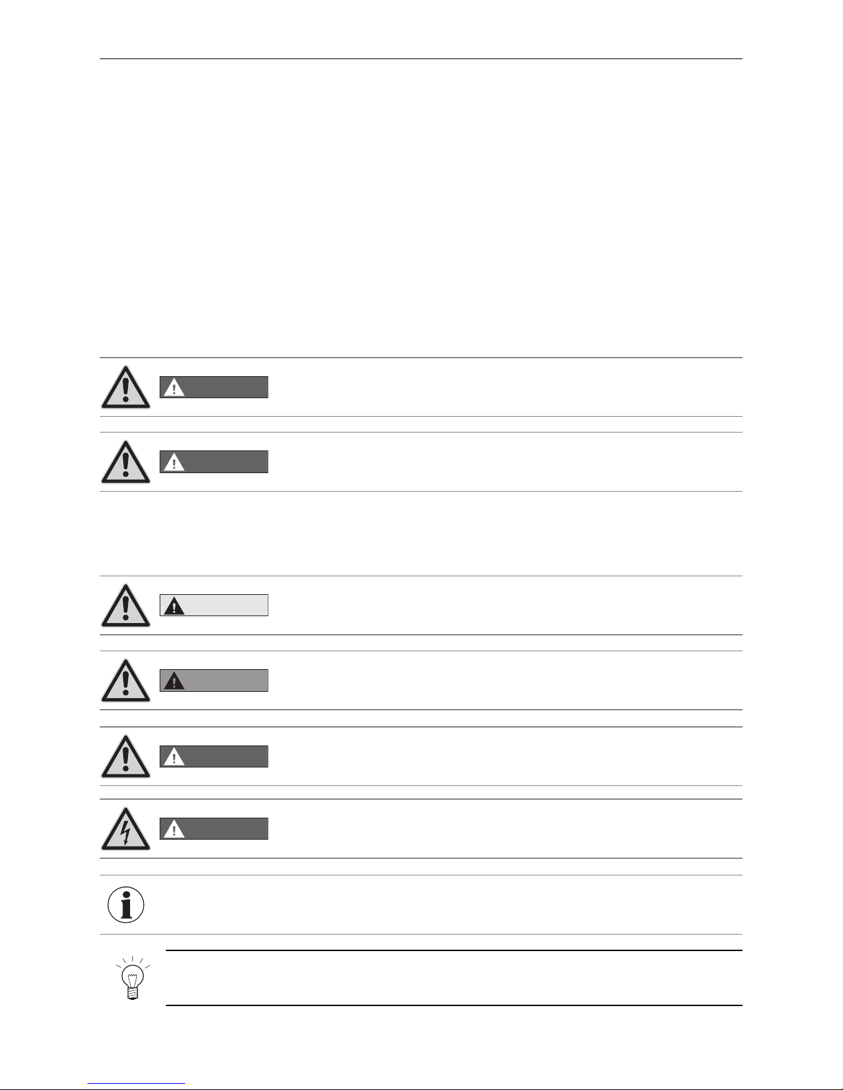
1.1.2 Caution symbols
1.1.1 Important information before you begin
This manual contains data with US units. The units in the original manual are European units. If there is a data
conflict between these units, the data with European units is always valid.
The original manual is written in German – this is an English translation. In case of conflicts, the German version
is always valid.
1. Important Information for the Technician
1.1 Safety precautions
The boiler/heater and related accessories are state of the art and meet all applicable safety regulations. Your
boiler/heater and all accessories operate using 110–120 V AC electric current. Improper installation or repair can
pose a threat of life-threatening electric shock. Installation should be performed only by appropriately qualified
technicians.
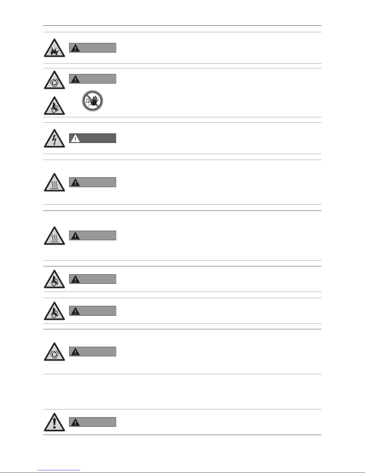
DANGER
Please follow the safety instructions (symbols) on the machine!
Please refer to the instructions in chapter 1.1.4!
DANGER
The specified safety requirements are to be followed in accordance with nationally
applicable regulations, standards, and guidelines.
CAUTION
This means you must follow the safety instructions. There is a slight risk of injury.
WARNING
This means that you must follow the safety instructions. There is a slight risk of
injury.
LabelidentGmbH Art.-N o.:W 08-05
DANGER
This indicates that there is a very serious risk of injury or death by high voltage.
INFORMATION
Ignoring the warnings identified can lead to malfunction of, or damage to, the boiler/heater or heating system.
DANGER
This means that it is essential that you follow the safety instructions. There is a
very serious risk of injury or death.
Note!
The blocks of text highlighted provide information and tips for operation.
Page 5
5
1. Important Information for the Technician
1.1.4 Safety instructions
1.1.3 Liability exclusion
All work should be performed exclusively by trained personnel. Local safety regulations must be complied with in
all cases; in the event of a conflict and/or contradiction between these regulations and the working instructions
in this document (e.g., impairment), then the local regulations should be adhered to in any event and the working
instruction should not be carried out; WINDHAGER ZENTRALHEIZUNG GMBH, ÖSTERREICH and WINDHAGER
ZENTRALHEIZUNG TECHNIK GmbH, ÖSTERREICH do not accept any liability for any injury to persons or damage
to property caused by incorrectly following the instructions and/or violating the local safety regulations! Subject
to modifications. No liability is accepted for errors in translation.
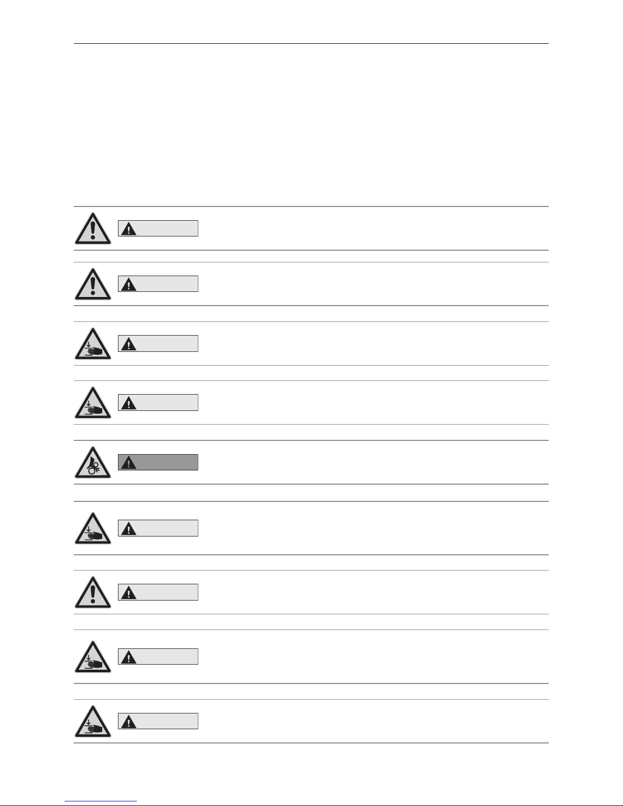
CAUTION
Risk of fire or explosion.
Do not use chemicals or fluids to start the fire.
CAUTION
Health and environmental hazard.
Do not burn garbage, gasoline, naphtha, engine oil, or other inappropriate materials.
CAUTION
Opening heating chamber door can crush and cut.
When opening door, never insert hands between the door and frame on the hinge
side of the heating chamber.
CAUTION
Closing heating chamber door can crush and cut.
When closing door, never insert hands between the door and frame of the heating
chamber. Be aware of other people, especially children.
WARNING
Entanglement hazard.
Do not open cover of auger conveyor when heating.
Handle with care when servicing charging screw.
CAUTION
Ash tray can crush and cut.
Never insert hands between ash tray and frame.
Never insert hands into closing bracket.
Never insert hands between ash tray and closing bracket.
CAUTION
Cover plate for pellet chamber can crush and cut.
Use caution when opening the cover plate.
Only authorized personnel are allowed to open cover plate.
CAUTION
Closing pellet chamber door can crush and cut.
Never insert hands between door and frame, or between door and closing bracket
of the pellet chamber when closing the door. Never insert hands into the hinge
area when opening door.
CAUTION
Opening pellet chamber door can crush and cut.
Never insert hands between door and frame on the hinge side of the pellet chamber when opening door. Never insert hands between door and closing bracket.
Page 6
6
1. Important Information for the Technician
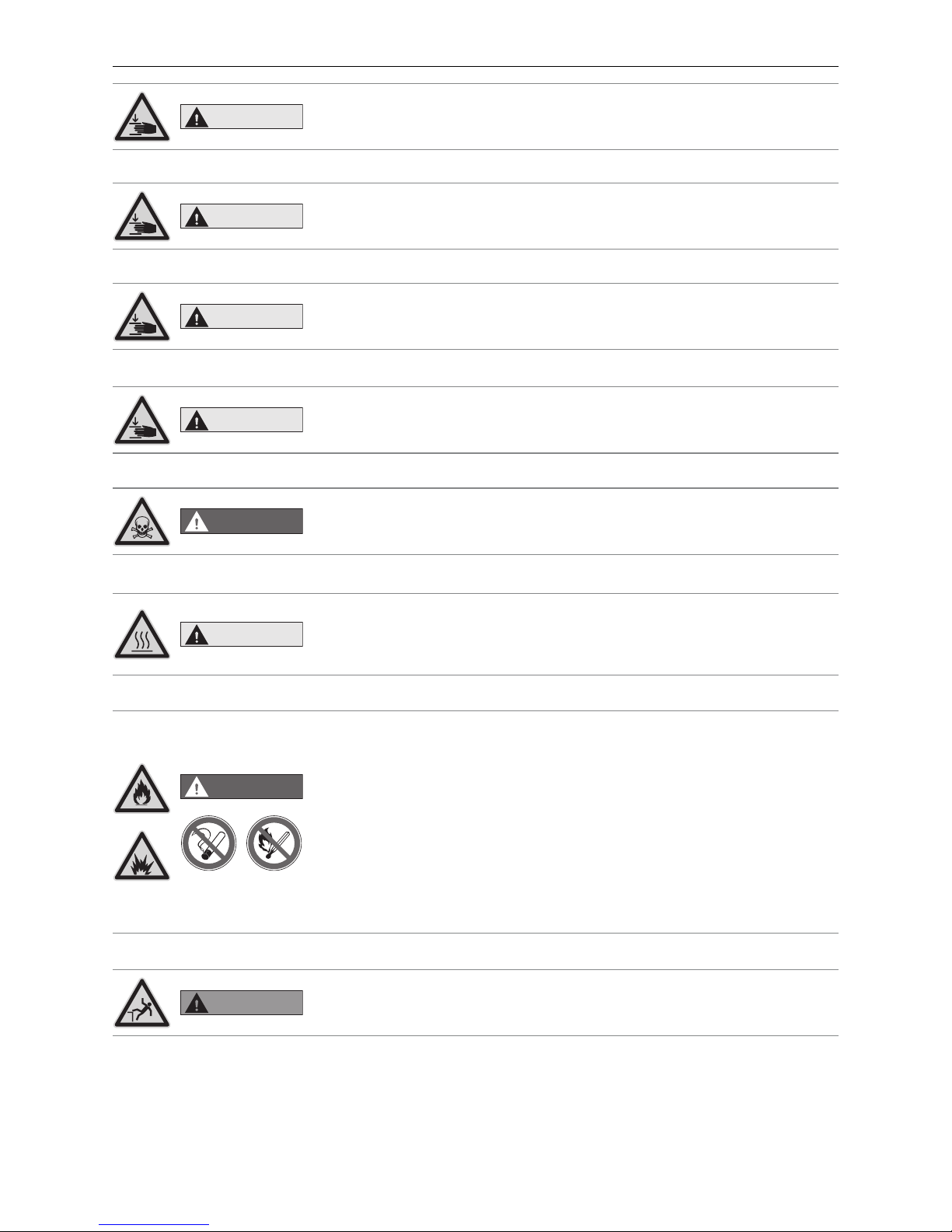
CAUTION
Removing the ash tray can crush and cut.
Never insert hands between frame of boiler/heater and ash tray when removing
the ash tray.
CAUTION
Mounting the ash tray can crush and cut.
Never insert hands between frame of boiler/heater and ash tray when mounting
the ash tray.
CAUTION
Displacing the ash tray can crush and cut.
When moving the ash tray, never insert hands between floor of the heating boiler
and ash tray.
CAUTION
Pinch point hazard.
Never insert hands between the cover plate and housing of heating chamber when
opening or closing.
DANGER
Danger - smoke gas.
Ensure adequate ventilation in the boiler room.
Smoke gas may cause poisoning.
CAUTION
Hot water and hot steam. Injury hazard.
Safety devices (such as the relief valve) will open automatically and release hot
water or hot steam. Keep away from safety devices. Do not operate safety devices
manually when system water is hot or when device is in operation
DANGER
Risk of fire or explosion.
Exposure may result in severe injury or death.
Do not fill with garbage, waste oil, gasoline, other flammable liquids, or any fuel
other than those listed on the rating plate.
Do not use chemicals to ignite fuel.
Do not use chemicals, sprays, or flammable substances to clean combustion room
or any other burner component.
Do not use boiler/heater cleaners.
Do not manually fill or light burner.
Do not smoke! Do not expose to open flame.
Do not expose to ignition sources.
Do not open combustion chamber door during operation, power failure, or alarms.
WARNING
Fall hazard.
Do not sit, stand, or walk on machine.
Keep children away.
Page 7
7
1. Important Information for the Technician
WARNING
Fire hazard.
Do not vacuum hot ash - may cause fire in vacuum cleaner.
Prior to vacuuming ash or dirt, wait until unit has shut down completely and has
cooled for at least 2 hours.
WARNING
Machine starts automatically.
Moving parts can crush and cut.
Do not remove guarding.
Do not touch rotating parts.
Keep children away.
Keep pets away.
LabelidentGmbH Art.-N o.:W 08-05
DANGER
Hazardous voltage.
Do not remove cover.
Keep away from electric components.
Disconnect power before servicing or cleaning.
WARNING
Injury hazard.
All components/surfaces remain hot for a long period of time after turning off unit!
Before cleaning or touching combustion chamber or any other components, turn
off unit completely and allow to cool for at least 2 hours
Use heat-resistant gloves.
Use tools provided.
WARNING
Health hazard.
Combustion particulates may contain harmful substances.
Use a fine-dust face mask during cleaning.
WARNING
Rotating parts can crush and dismember.
Keep hands out of feed opening.
Do not remove cover during normal operation.
WARNING
Burn hazard – hot surface.
Do not touch frame, cover, or inside of heating chamber during heating.
Allow heating chamber to cool completely before cleaning and servicing.
Keep children and pets away from heating chamber.
Do not touch backside, chimney, or any other pipework during operation.
Maximum draft marked on nameplate.
WARNING
Hand crush hazard.
Automatic start-up if safety switch is activated.
Do not push safety switch.
Moving parts behind the combustion chamber door may start automatically, which
can lead to loss of fingers or other serious bodily injury.
Disconnect power before opening the combustion chamber door.
WARNING
Risk of health hazard.
Do not connect to an existing boiler/heater system.
Page 8
8
1. Important Information for the Technician
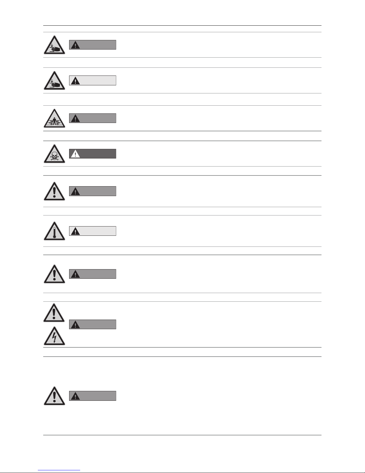
WARNING
Risk of hand injury.
Use caution when opening the cleaning flap, as it can open suddenly.
When opening the cleaning flap, use the tool provided and wear protective gloves.
CAUTION
Pinch point hazard.
Use caution when closing the cover of the smoke funnel chamber.
WARNING
Crush hazard.
Remain alert and aware of surroundings when moving the machine with crane or
fork lift.
DANGER
Smoke gas danger.
Mount a warning plate against smoke gas on the boiler room door.
WARNING
Health hazard.
In case of an unexpected fire or if flue pipe turns red, disconnect power if the main
switch or main circuit breaker is safe to reach. Call the fire department (911) and
evacuate the building. Do not enter smoke-filled rooms to disconnect power.
CAUTION
Injury hazard by hot water or steam.
Safety devices (such as relief or drain valve) will open automatically and relieve hot
water or steam. Keep away from safety devices. Do not manually operate safety
devices when the system is hot.
WARNING
Health hazard from chemical substances.
Some states list chemical substances known to cause cancer, birth defects, death,
serious illness, or other reproductive harm in propositions. This product may contain such substances, either from the fuel, fuel combustion, or in components of
the product itself.
LabelidentGmbH Art.-N o.:W 08-05
WARNING
Necessary tasks.
The heat exchanger, flue pipe, and chimney must be cleaned regularly to remove accumulated creosote and ash. Ensure that the heat exchanger, flue pipe, and
chimney are cleaned at the end of each heating season to minimize corrosion during the summer months. The appliance, flue pipe, and chimney must be in good
condition. These instructions also apply to a draft inducer, if used.
WARNING
Pellet feed system: service, maintenance and rules
The pellet feed system operates automatically. All service and maintenance must
be completed by trained specialists only. Do not alter the equipment or accessories in any way.
For use in combination with Windhager BioWIN XL pellet-fueled central heating
boiler/furnace only.
Do not use to transport any material other than wood pellet fuel listed on the boiler
nameplate or in the boiler manuals.
Do not use for vacuum cleaning.
The pellet feed system starts automatically and will make noise. People who are
easily startled or have cardiac problems should keep away.
Page 9

9
1. Important Information for the Technician
DANGER
Pellet feed unit: fire and explosion hazard
Can lead to serious injury/death! Ground suction hoses must be installed as described in the installation instructions at every connection to avoid static sparking/
dust ignition. The pellet feed unit is for use with the day hopper only. The feed unit
must be braced, anchored, or strapped to avoid falling/shifting during an earthquake. Instructions can be obtained from your local Windhager dealer or wholesaler.
Pellet feed automatic changeover unit: Fire and explosion hazard
Fire and explosion hazard can lead to serious injury or death.
Do not use the pellet feed automatic changeover unit inside pellet storage room
or where there is a lot of dust present. Connect delivery hoses to pellet feed automatic changeover unit as described in the installation instructions to avoid static
sparking or dust ignition.
LabelidentGmbH Art.-N o.:W 08-05
WARNING
Pellet feed automatic changeover unit: injury hazard by moving parts and electricity
Can lead to serious injury or death.
Device starts automatically. Device restarts automatically after power failure.
Do not remove cover.
This part should be serviced by trained personnel only.
WARNING
Clearances and installation instructions
Minimum clearances from combustible or noncombustible construction:
2 inches left, 12 inches back, 24 inches top (right),
6 inches right side, 22 inches front.
Access to the back side is required to allow the service of parts such as the drain
valve, relief valve, and inspection fittings.
This unit is for dry indoor installation only. Not for installation on combustible flooring. Not for installation in manufactured homes or mobile homes.
DANGER
Risk of serious bodily injury or death.
This boiler/heater is equipped for one type of wood pellet only. Read the nameplate
behind top lid for the correct type of pellet. Do not use this boiler/heater with any
fuel other than the one listed on the name plate. Failure to use the correct fuel
may cause problems resulting in death, serious bodily injury or property damage.
WARNING
Fire hazard.
Do not operate with incorrect draft. Check nameplate behind top lid for correct
draft.
Do not operate while refilling the bulk hopper.
Do not operate with door or ash removal covering open or when the ash box is
removed.
Do not store fuel or other combustible material in the boiler room.
Regularly inspect and clean flues and chimney.
Have a trained professional regularly inspect safety devices, such as the relief and
drain valves.
LabelidentGmbH Art.-N o.:W 08-05
CAUTION
Caution
For supply connections, only use 10 AWG or larger wires acceptable for at least
176°F (80 °C) on a GFCI circuit!
Page 10
10
1. Important Information for the Technician
1.3 Boiler room/Installation room
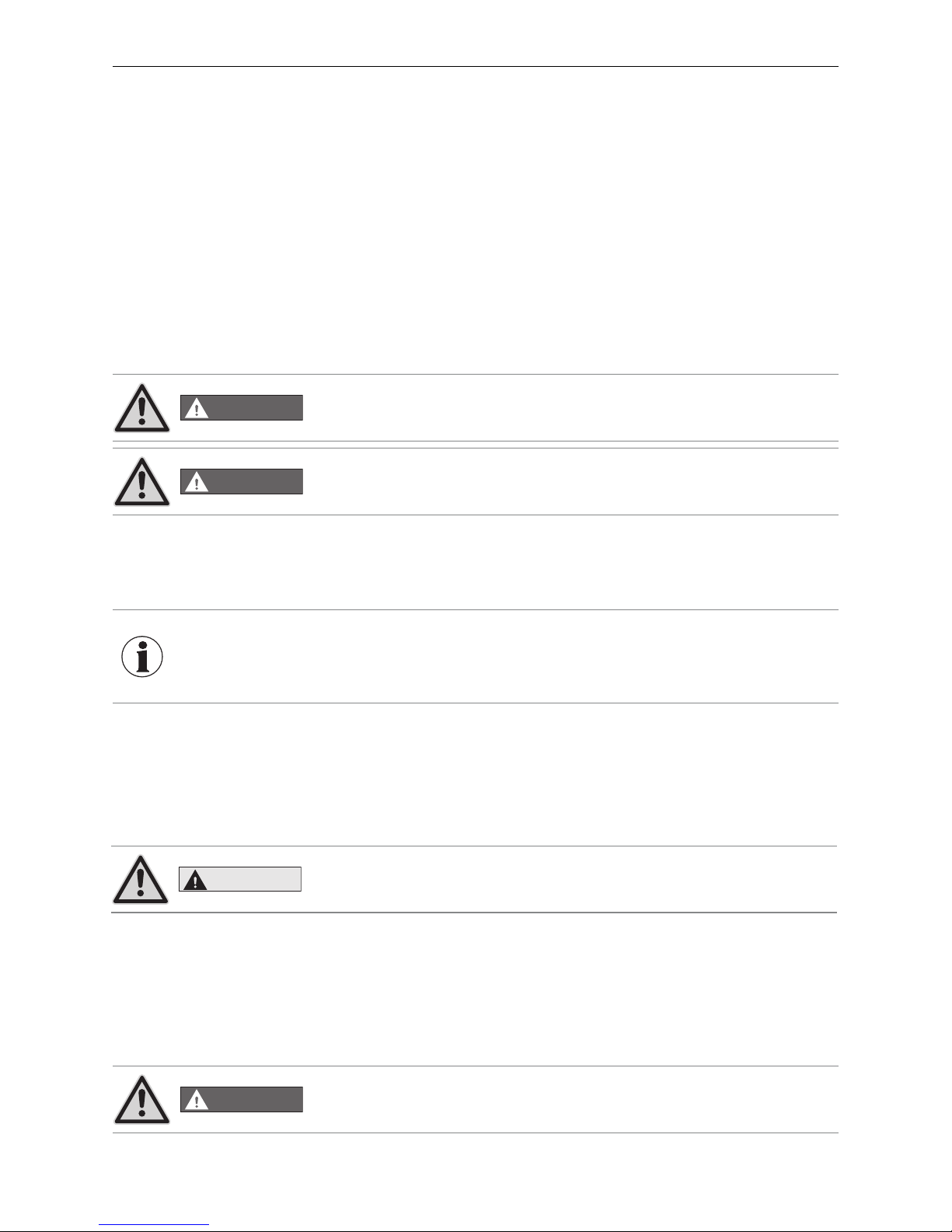
DANGER
The configuration of the entire system must comply with technical fire protection
requirements in accordance with regional legislation, applicable regulations, standards and guidelines.
1.2 Flue
A properly dimensioned flue is required for the optimal and safe function of this device.
The design of the entire flue system must meet local building codes, and all components must meet
UL 2523 / UL 103. All relevant data to size a flue properly is listed under“technical data for flue gas calculations.“
Because of the device‘s low minimum flue gas temperature, a moisture and water resistant flue gas system is
required. The use of a double wall stainless steel system is required.
A brick chimney may be used if it is damp and water resistant (e.g., refractory brick), properly insulated, and
fulfills the requirements of technical calculations. In the case of an existing chimney that is non-damp and water
resistant, a single wall stainless steel pipe that is properly designed and insulated may be used. In either case,
ask a local building inspector or flue expert for the correct design and flue sizing.
For directions on installing and supporting your chimney, follow instructions provided by your flue system‘s
manufacturer.
A pressure relief valve needs to be installed in the flue gas system. Whenever possible, a barometric damper should
be installed according to local building codes. DO NOT install a barometric damper in sleeping or living areas!
The minimum draft required at the flue gas collar is -0.02 in H2O (-0.05 mbar).
The maximum draft allowed at the flue gas collar is -0.08 in H2O (-0.2 mbar).
The minimum flue pipe diameter required is 5.1 inches / 130 mm. The use of a flue pipe diameter greater than
5.9inches / 150 mm first requires a calculation from your local building inspector or flue expert.
DANGER
Injury hazard.
Draft regulators which open inwards and outwards can release fumes which can
lead to asphyxiation.
DANGER
Injury hazard.
The use of galvanized flue gas pipes is at your own risk - this may cause
condensation and consequently damage the pipes.
1.2.1 Adjusting the barometric damper
Adjust barometric damper according to the manufacturer‘s instructions. To access the measurement open,ing,
remove the back lid and plug at the flue gas collar. Measure the draft with an appropriate analyzer. Adjust for the
flue draft listed on the boiler/heater name plate. Replace the plug and close the lid after measuring the draft.
CAUTION
Do not alter for increased firing for any reason!
READ and FOLLOW installation instructions for proper flue sizing and flue design! All flue systems must meet
UL103. All flue systems must be water resistant (st ainless steel) and insulated (double wall system).
DO NOT INSTALL BAROMETRIC DAMPER OR PRESSURE RELIEF VALVE IN LIVING OR SLEEPING AREA!
INFORMATION
Frequently, overhauling existing systems involves over-sized flue cross-sections
or flues not designed for low-temperature operation. We recommend an evaluation by the local building inspector before installing the boiler system. In this way
appropriate modifications can be made to the flue before system installation (see
technical data for flue calculation values).
Page 11
11
1. Important Information for the Technician
1.4 Fuel storage
The pellets must be stored in a dry location in order to achieve trouble-free operation with optimum combustion
at maximum efficiency. The pellets can be stored in bulk in a storage room, sheet steel tank, fabric tank or buried
tank. The requirements for pellet storage are defined in ÖNORM M7137 for Austria, the Firing Ordinance FeuV
for Germany, or the Pellets Fuel Institute (PFI) Standard for the USA/Canada.
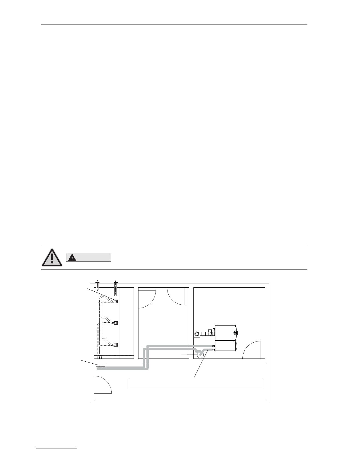
Maximum transport length or height for a pellet feed system:
These max. values require a stable power supply (min. 110 V AC under load!). The suction turbine must be in the
same room as the pellet boiler. The distance between the pellet boiler and the suction turbine must not exceed
9.8 ft / 3 m – Fig. 2.
Max. distance of 82 ft / 25 m between furthest probe and pellet boiler/heater with max. total height difference of
5.9 ft / 1.8 m
Max. distance of 50 ft / 15 m between furthest probe and pellet boiler/heater with max. total height difference of
9.2 ft / 2.8 m
Max. distance of 33 ft / 10 m between furthest probe and pellet boiler/heater with max. total height difference of
14.8 ft /4.5 m
Total height difference: Sum of lengths of all rising pipes
Fig. 2 Storage room, heating room – view from above
Furthest away probe
Changeover unit
Storage room
Suction turbine
BioWIN XL
Boiler room
Suction pipe from BioWIN XL to suction turbine: Max. length 9.8 ft/3 m
CAUTION
The pellets must be transported carefully in and out of the storage room in order
to maintain good pellet quality.
– You must comply with the minimum clearances for connections, cleaning and maintenance – see section 2.2
Minimum service clearances.
– Sufficient ventilation of the set-up area must be guaranteed - see section 2.4 Combustion air.
– The boiler must be installed in a dry location.
– The boiler must not be installed in rooms that are very dusty or humid.
Permissible limit values: Air humidity: 85 % at room temperature of 77 °F / 25 °C (non-condensing)
Room temperature: 35.6 °F to 104 °F / +2 to +40 °C
– Sufficient lighting must be provided for service and maintenance.
Page 12
12
2. For the Installer
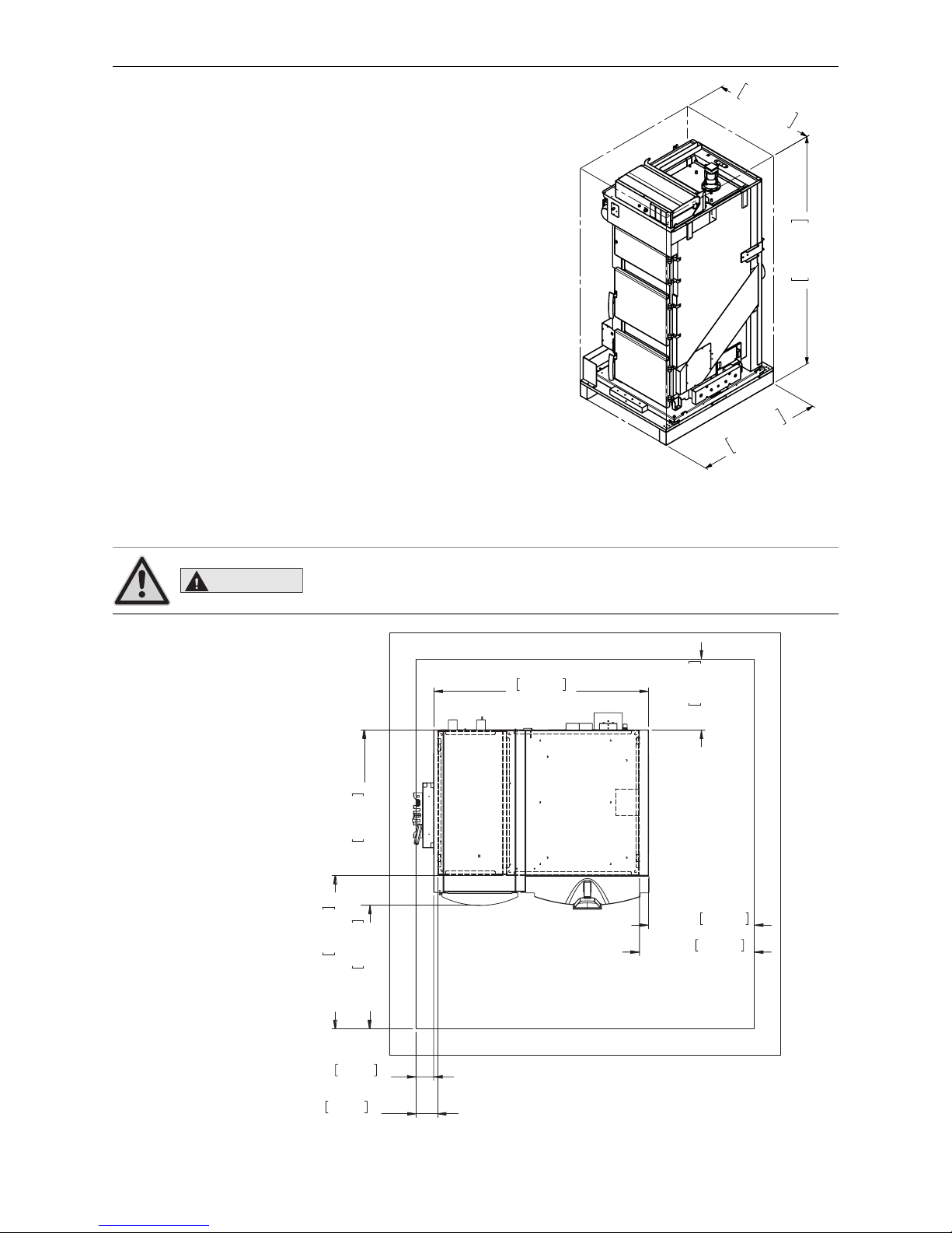
2.2 Minimum clearances
All dimensions in mm:
A = Distance from edge of base
B = Distance from edge of cladding
1220mm
48,03in
996mm
39,19in
min.
400mm
15,75in
(B) min.
700mm
27,56in
(A) min.
652mm
25,66in
(A) min.
122mm
4,79in
(B) min.
600mm
23,62in
(B) min.
100mm
3,94in
(A) min.
871mm
34,27in
.9.HVVHOYRUODXI5RKU
.5.HVVHOU¾FNODXI5RKU
797KHUPRYHQWLOI¾KOHUQXU7\SH%:0XIIH
6%6LFKHUKHLWVEDWWHULHQXU7\SH%:5RKU
((QWOHHUXQJ
$3HOOHWV]XI¾KUXQJLQPP5RKU
%5¾FNOXIWLQPP5RKU
.7.HVVHO7HPSHUDWXUI¾KOHU
=/=XOXIW
Fig. 4 BioWIN XL – view from above
Minimum room height: 1900 mm / 74.8 in.
2. For the Installer
2.1 Scope of delivery, packaging
2.1.1 Boiler
The boiler is supplied on a wooden pallet covered with a plastic sack
– Fig. 3. The cladding parts are in a separate cardboard box. Cleaning
tools are packed in the combustion chamber and the ash chamber.
In addition, the pellet feed unit is packed in several cardboard boxes.
2.1.2 Optional accessories
Accessories for fully-automatic pellet feed
– Fully automated changeover unit with/without fire protection
collars including 3x suction probes
– Fully automated changeover unit with/without fire protection unit
including 8x suction probes and masonry feed-through
– Delivery hose with flexible ground leads, DN 50 - 25 m / 82 ft (sup-
ply and return air hoses)
30,71in
780mm
70,47in
1790mm
38,39in
975mm
Fig. 3 Installation dimensions – BioWIN XL
CAUTION
Follow the installation guidelines for boiler rooms!
Page 13
13
2. For the Installer
2.3 System
These boilers/heaters are designed and approved as heat generators for hot water heating systems
with permissible flow temperatures of up to 194 °F / 90 °C.
The maximum flow temperature is factory-set at 185 °F /
85°C. They may be installed only in sealed systems.
2.3.1 Standards
The following UL listed components must be completely unobstructed on the boiler/heater:
– Pressure Relief Valve with 30 psi opening pressure Article no.: 003493
– Low Water Cut-Off with Manual Reset for 110–120 V 15 A Article no.: 003495
– Pressure Gauge Article no.: 003494
– Expansion Tank with at least 15% total system water volume capacity Article no.: 003496, 003497, 003498
– Automatic Air Vent Article no.: 003499
READ and FOLLOW installation instructions for proper flue sizing and flue design!
All flue systems must meet UL103. All flue systems must be water resistant (stainless steel) and insulated (double
wall system).
DO NOT INSTALL BAROMETRIC DAMPER OR PRESSURE RELIEF VALVE IN LIVING OR SLEEPING AREA!
2.3.2 Operation with external control and buffer only
The following requirements must be met.
– an acumulatorr tank (min 100 gal) is mandatory
– a return hold up group = boiler protection group (113 °F / 45 °C) is mandatory
– To ensure the boiler minimum temperatures and the pump lag time, the transfer/hot water tank circuit pump
and the external heat requirement must be connected on the electrical panel to the intended terminals.(see
BioWINXL connection diagram).
2.3.3 Heating water
CAUTION
The chemical composition of the heating water must conform with local legislation
and meet the directives, guidelines and standards.
Applicable for Austria (excerpt from ÖNORM H 5195):
a) According to ÖNORM M 5195 (2010 edition), the condition of the heating water must be checked every 2 years
by a heating technician in order to avoid corrosion and sediment accumulation in the heating system.
b) The pipe lines and heating appliances should be thoroughly rinsed before the boiler is connected.
c) To protect the boiler from contamination from the heating system, installation of a dirt trap is required in old
or existing systems 5 with maintenance cocks installed in the return line.
d) If oxygen diffusion or sludge build-up cannot be prevented, the system must be segregated by means of a heat
exchanger.
e) If antifreeze is used, a minimum volume of 25 % antifreeze is required, otherwise corrosion prevention is not
guaranteed.
Page 14

14
2. For the Installer
Water hardness according to ÖNORM H5195-1 (2010 edition)
Highest permissible hardness of filling water for heating systems, heat generator with a water content of > 0.3 l/kW:
Specific water volume of the system < 1.55 gal/kBTU (20 l/kW): *
Overall performance of heat output Total alkaline earth °dH °fH
≤ 170.6 kBTU/hr up to 3.0 mmol/l up to 16.8 30
> 170.6 kBTU/hr to ≤ 682.4 kBTU/hr up to 2.0 mmol/l up to 11.2 20
Specific water volume of the system ≥ 1.55 gal/kBTU (20 l/kW) but < 3.87 gal/kBTU (50 l/kW) : *
Overall performance of heat output Total alkaline earth °dH °fH
≤ 170.6 kBTU/hr up to 2.0 mmol/l up to 11.2 20
> 170.6 kBTU/hr to ≤ 682.4 kBTU/hr up to 1.0 mmol/l up to 5.6 10
Specific water volume of the system ≥ 3.87 gal/kBTU (50 l/kW) : *
Overall performance of heat output Total alkaline earth °dH °fH
≤ 170.6 kBTU/hr up to 1.0 mmol/l up to 5.6 10
> 170.6 kBTU/hr to ≤ 682.4 kBTU/hr up to 0.5 mmol/l up to 2.8 5
* At an annual replenishment of maximum 5% of the system‘s water content; additionally, we comply with ÖNORM H5195 part 1 and VDI 2035 T1.
Important general comments on water quality
The boilers are intended for operation with clean, good quality tap or drinking water. The water should be clear
and free from visible impurities and suspended matter.
Most heating systems are comprised of different materials. Therefore, a water treatment is recommended to
prevent or limit problems (metal corrosion, calcification and sludge formation, microbiological contamination,
chemical changes in unprepared system water).
Reduce the oxygen volume in the heating circuit as much as possible.
Annually refill a maximum of 5 % of the system‘s water capacity.
Important general comments on water quality for new systems
New systems must be fully cleaned from any residue (plastic waste, lubricants, etc.) by means of a universal
cleaning agent. Rinse with a minimum of three times the installation volume of the central heating system.
Cleaning with chemical products must be done by a professional. Carefully rinse the system until the rinse water
is clear and free from any impurities.
The water must not be softened to less than 0.5°dH, as water any softer harms the system. An inhibitor must be
used in combination with a water softener.
The heating system must only be filled with fresh, untreated drinking water (pH between 8.2 and 10.0). Observe
the information in the table to avoid any problems with the boiler or system. If one or more of the conditions cannot be met, it is recommended to treat the heating water. In cases of improperly cleaned systems or poor water
quality, the guarantee and warranty are void.
Heating water quality
Acidity 8.2 – 10.0 pH
Electrical conductivity ≤ 800 μS/cm at 25 °C
Chloride ≤ 30 mg/l
Other substances < 1 mg/l
Page 15
15
2. For the Installer
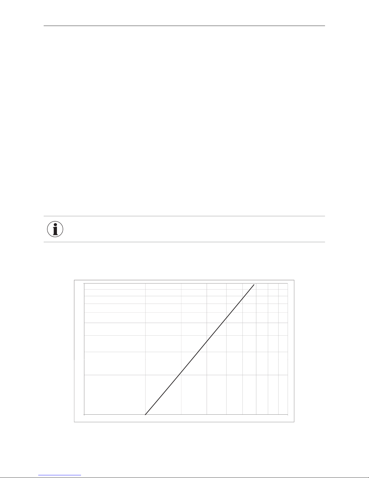
2.3.4 Water-side resistance (pressure loss)
Pressure loss (psi)
BioWIN XL
Diagram 1
1
0,1
200 2000
INFORMATION
If using a buffer, the BioWIN XL return flow temperature must be increased – see
hydraulic diagram in the planning documents.
Important general comments on water quality for existing systems
– De-sludge the system.
– Rinse the system.
– Clean the system with a universal cleaning agent to remove waste material (copper, fiber mass, welding paste).
– Carefully rinse the system until the water is clean and free of any impurities. Check the connection tightness
of the combustion air supply and extraction.
The thorough cleaning of the system must be performed by a professional. A sufficient and controlled flow is
required to remove all impurities and residues from the heating circuit. In the case of cleaning with chemical
products, the above points are especially important for avoiding any residues from corrosive products.
In the event of considerable impurities/clogging (deposits of lime), the boiler must be cleaned by a professional
with appropriate tools.
Circulation filter/dirt trap
The installation of a dirt trap is recommended. In accordance with ÖNORM H5195, a filter sharpness of ≤ 25 μm
is required.
Water treatment
The compatibility of the product with all system materials must be checked when using a water treatment system.
Observe the manufacturer’s instructions.
The water must be regularly checked, and if necessary, changed.
Practical advice:
The system‘s water quality must be regularly checked by a professional (at least every two years), especially
after filling or refilling the water. Record all treatment measures in a report to document the maintenance work
on the boiler and system.
Flow rate (gal/h)
Page 16

16
2. For the Installer
Pellet boiler BioWIN XL
Max. induction length
(Air intake)
49.2 ft / 15 m, each 90° bend reduces induction length by 3.3 ft / 1 m
Air intake cross-section
Min. diameter 5.9 inches / 150 mm
(or technically equivalent cross-section)
Combustion air line
(Air intake)
DN 160
Seal integrity: min. 3.53 ft3/hr or 0.1 m3/h at 0.1 mbar; temperature resistance: 203 °F / 95 °C
(commercially available plastic drain pipes with correctly inserted seal)
Connecting piece
(Flue gases)
Max. length 9.8 ft / 3 m,
only pipes with minimum classification acc. to EN 1851-1:
T200 H1 D V2 L(xxxx) G(xx) are to be used.
Shaft head Tested wind protection fixture or design in accordance with DIN V 18160-1 – Fig. 5.
Air/flue gas system
(sketch Fig. 5)
Configuration as equal-pressure system
(induction opening for air intake and opening for flue gas discharge are within a
square with a max. edge length of 1.6 ft / 0.5 m)
Required accreditations: for solid fuels; moisture-resistant
Swinging draught flap,
explosion flap
Energy-saving intake regulators or explosion flaps are not allowed to be installed in the living
area. Comply with the statutory regulations and directives.
2.4 Combustion air
An adequate supply of combustion air is absolutely essential. The combustion air must be free of pollutants (gases,
vapors, and dust), or malfunctions and increased wear (e.g., corrosion) may occur.
2.4.1 Operating with room air
Combustion air supplied directly from the installation room
If combustion air is drawn directly by the system from the boiler/heater room, the room must be adequately ventilated. The combustion air should be directed near the boiler.
The minimum area of free cross-section must be 0.11 in2 / kBTU (2.5 cm2 / per kW) of the boiler‘s nominal total output1.
The ventilation opening to the outdoors for combustion air should be designed as follows:
– the flow of air must not be restricted in any way by the weather (e.g., snow, leaves),
– the free cross-section area remains the same when taking the cover grille, discs, etc. into consideration.
2.4.2 Operating independently of the room air
Combustion air supplied from ventilation draught in the flue
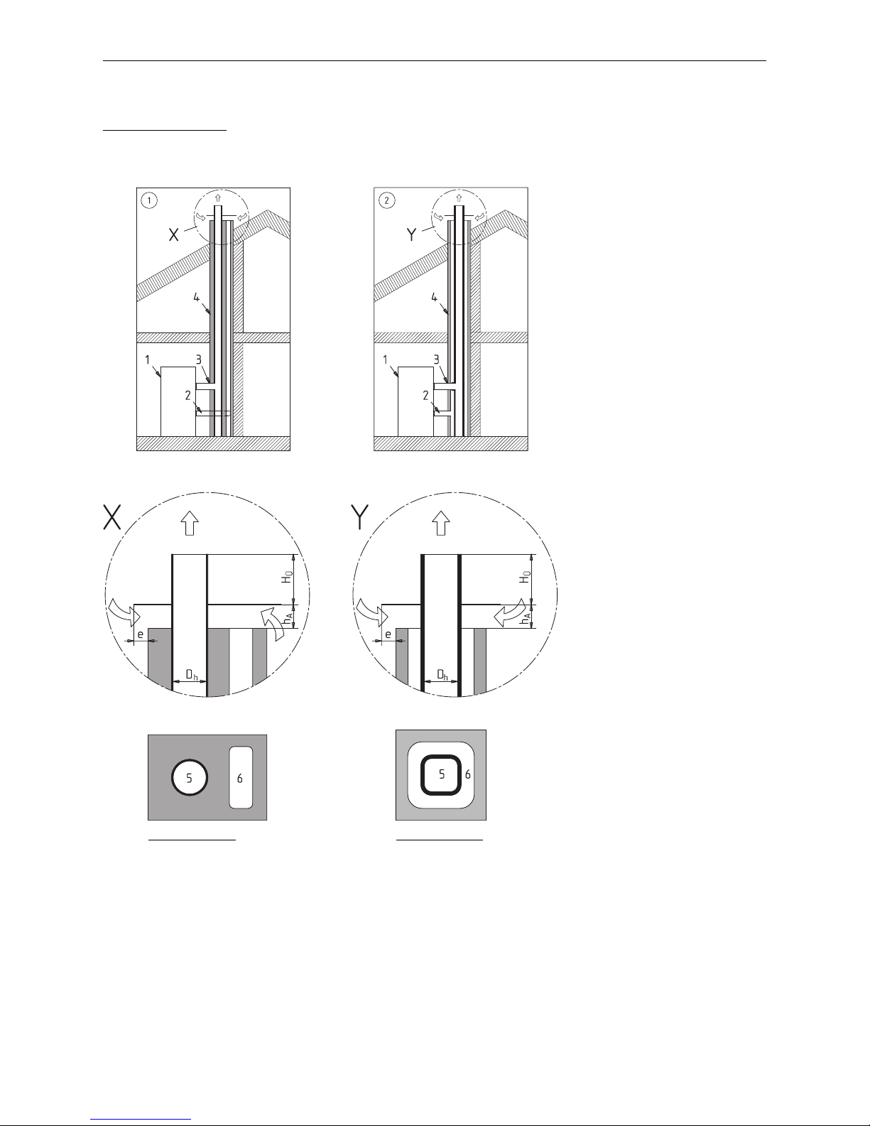
The combustion air is drawn in through an unobstructed ventilation draught in the chimney – Fig. 5. The openings
for the intake air and the flue gas are only allowed to be located with a square with a 19.7 inches / 500 mm side
length. This ensures that the same air pressure is always present in the openings (even in very windy conditions).
Only flue gas systems that have been tested and approved for solid fuel applications may be used.
In the BioWIN XL, the air intake pipe can be connected directly (without accessories).
The lengths stated are only a guideline and should not take the place of an actual flue calculation.
1
The boiler‘s nominal total output is the sum of the nominal outputs of all heat generators installed in the same boiler / installation room.
INFORMATION
Malfunctions or complaints occasioned by inadequate combustion air will not be
covered by the guarantee!
Page 17
17
2. For the Installer
Fig. 5 Sketch of ventilation draught in flue
Hearth with flue gas blower to DIN 18897-1 (type FX
42X
) for connection with a pressure-equal
air/flue gas system
Examples of models:
Air/flue system with parallel
supply air/flue layout
Air/flue system with concentric supply
air/flue layout
1 ...........Pellet boiler
2 ...........Combustion air line (intake air)
3 ...........Connecting piece (flue gas)
4 ...........Air/flue gas system
Detail X, Y
Opening (shaft head in accordance
with DIN V 18160-1)
DH .......flue gas diameter
HÜ .......spacing of opening
HA ........spacing of dispersion plate
E ..........protrusion of dispersion plate
5 ...........Flue gases
6 ...........Combustion air (intake air)
Requirements:
HÜ ≥ 2 x DH
HA = min. 3.9 inches / 10 cm
E= 0 to 3.1 inches / 0 to 8 cm
Requirements:
HÜ ≥ DH
HA = min. 3.9 inches / 10 cm
E= 0 to 3.1 inches / 0 to 8 cm
The connection for the chimney connecting piece should be designed so that the condensate is prevented from
flowing back into the connecting piece from the chimney.
Page 18
18
2. For the Installer
2.5 Installation sequence
a) Transport boiler to installation site and remove transport protection – see section 2.6.
b) Fit side integral fuel hopper and cladding – see section 2.7.
c) Fit exhaust pipe – see section 2.8.
2.6 Setting up, preparing for installation
– Transport boiler to installation site on wooden pallet.
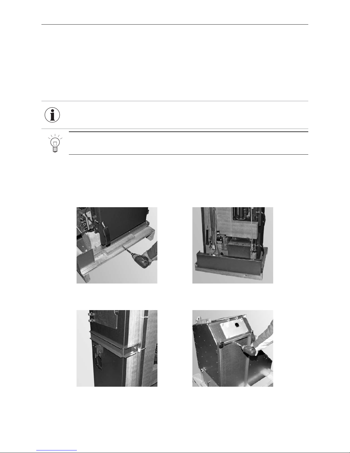
Fig. 6 Removing transport screws Fig. 7 Removing transport protection
Fig. 8 Removing transport bracket Fig. 9 Removing crate and unscrewing
floor plate of integral fuel hopper
– The boiler can be installed directly on a non-flammable surface and does not require special foundations.
If foundations have been provided, we recommend that they be made according to the boiler dimensions to
ensure that the four set screws make contact properly.
– Remove 2 x transport screws at front and back – Fig. 6.
– Remove transport protection and transport bracket – Fig. 7 and Fig. 8.
– Remove crate and unscrew floor plate of integral fuel hopper – Fig. 9.
Tip!
The rear transport bracket is intended for clamping to a barrow – Fig. 6.
INFORMATION
For information on installing the suction probes in a sheet steel tank or fabric tank,
refer to the installation instructions for sheet steel and fabric tanks. For information about configuring pellet stores, see the planning document ”Pellet stores for
pellet boilers.”
Page 19
19
2. For the Installer
1
2
4
5
6
7
8
9
10
21
22
11
18 19
20
23
12
15
16
14
3
13
24
26
25
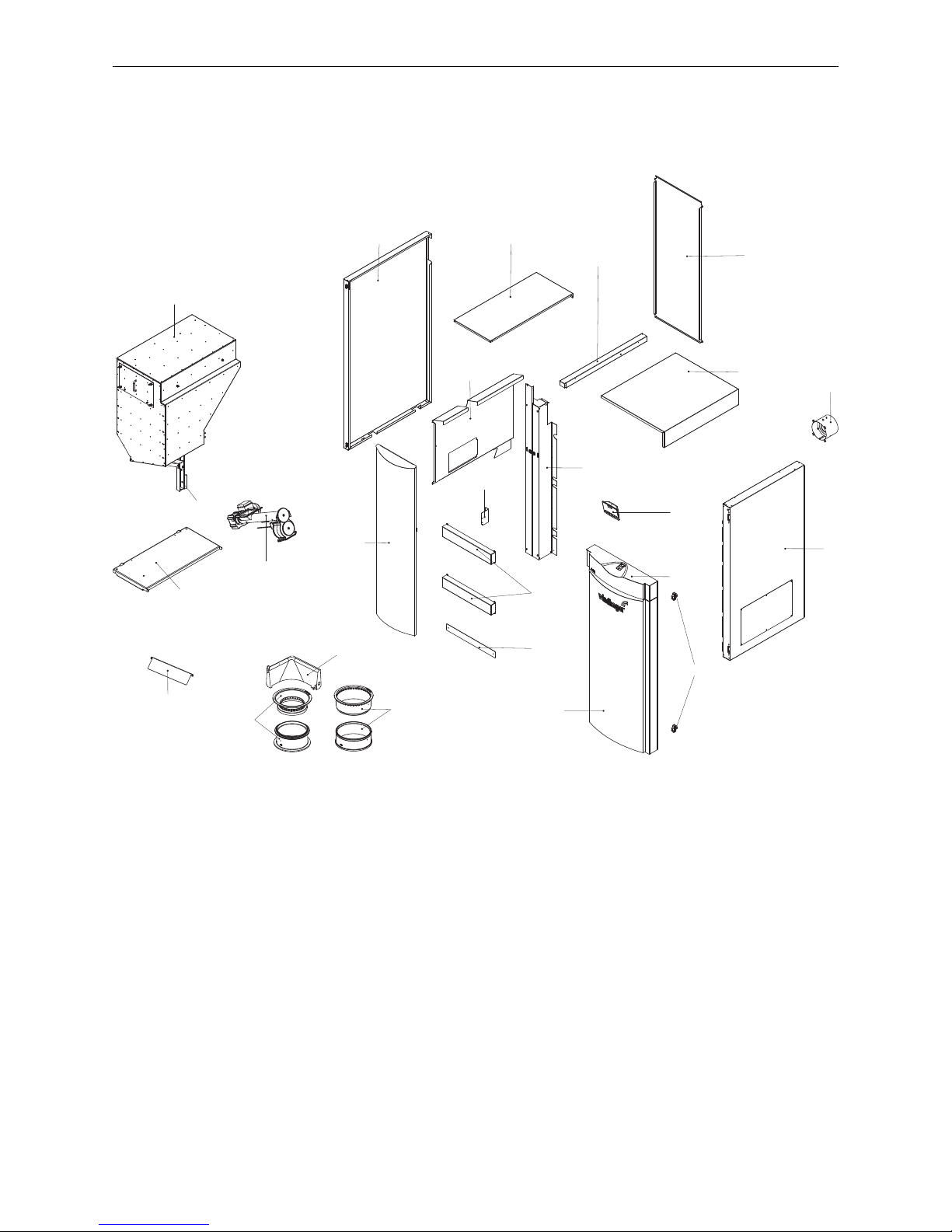
2.7 Installation
The cladding of the BioWIN XL consists of the following parts:
Fig. 10 Parts of BioWIN XL
1 ...........Rear wall
2 ...........Cladding cover
3 ...........Intake fitting
4 ...........Right side panel
5 ...........Hinges
6 ...........Cladding door cover
7 ...........InfoWIN
PLUS
8 ...........Cladding door, right
9 ...........Base panel
10 .........Centre panel, horizontal
11 .........Cladding door, left
12 .........Auger tube rotary feeder unit
13 .........Access ramp
14 .........Floor plate
15 .........Integral fuel hopper support
16 .........Integral fuel hopper
18 .........Left side panel
19 .........Integral fuel hopper cladding cover
20 .........Top right fuel hopper cladding
21 .........Centre panel, vertical
22 .........Hand guard bracket
23 .........Side anti-contact protection
24 .........Ash wedge (BioWIN XL 350 NA only)
25 .........Top and bottom cone parts (BioWIN XL 350 NA)
26 .........Top and bottom cone parts (BioWIN XL 450 NA / 600 NA)
Page 20
20
2. For the Installer
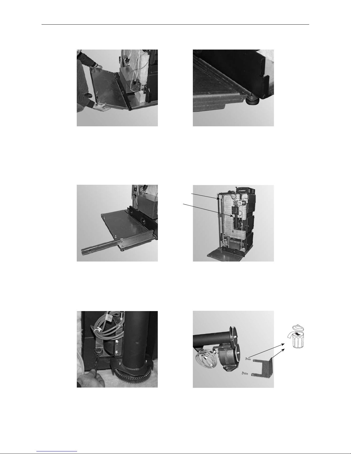
– Fit floor plate (part 14, attached to integral fuel hopper for transport, see Fig. 9) on left side – Fig. 11, Fig. 12.
Fig. 11 Attaching the floor plate Fig. 12 Attaching the floor plate
– Align the boiler and floor plate with the set screws horizontally or slightly inclined toward the rear – Fig. 13.
– Remove support for integral fuel hopper (part 15) from boiler by removing transport attachments (cable ties)
– Fig. 14.
– Unscrew auger tube rotary feeder (part 12) with transport attachments (sheet metal brackets) from boiler
(Fig. 15) and remove transport attachments – Fig. 16.
Fig. 13 Aligning boiler Fig. 14 Boiler aligned with floor plate
Fig. 15 Unscrewing transport attachments
from boiler
Fig. 16 Unscrewing transport attachments
from rotary feeder
Integral fuel
hopper support
Auger tube
Page 21
21
2. For the Installer
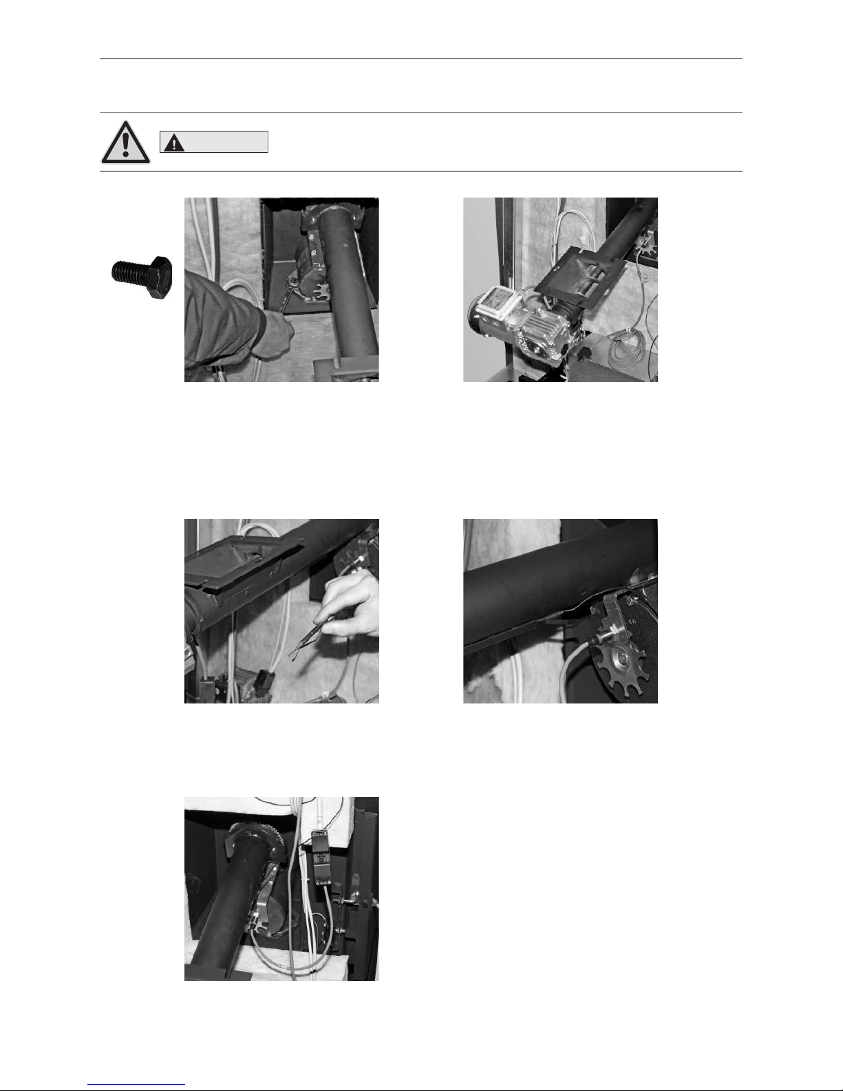
– Screw auger tube rotary feeder to boiler with 2 hexagon screws (M10 x 20) – Fig. 17, Fig. 18.
Fig. 17 Mounting auger tube
rotary feeder unit
Fig. 18 Auger tube rotary
feeder unit - mounted
– Slide sensor for auger tube safety thermostat together with sensor guard (Fig. 19) into sensor holder as far as
it will go – Fig. 20.
– Connect 3-pin plug for rotary feeder proximity switch – Fig. 21.
Fig. 19 Sensor and sensor guard Fig. 20 Inserting sensor and sensor guard
into holder on auger tube
Fig. 21 Connecting 3-pin plug for proximity switch
2x
M10 x 20
CAUTION
Ensure tight seal between rotary feeder and boiler.
Page 22
22
2. For the Installer
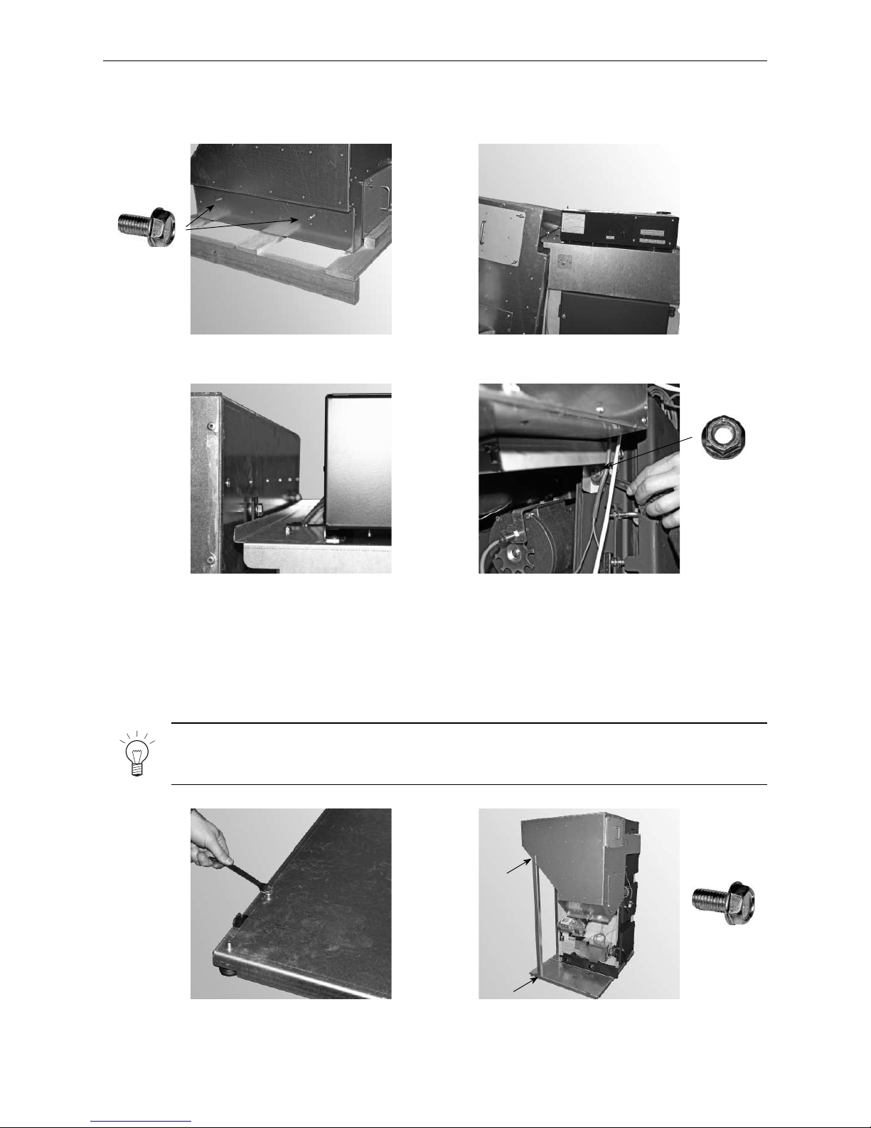
– Fit 2 TT screws (M8 x 16) about 1/3 of the way into the side of the integral fuel hopper – Fig. 22.
– Fit integral fuel hopper (part 16) with inserted screws into the 2 lugs at the top. Tighten screws – Fig. 23, Fig. 24.
– Secure integral fuel hopper below at front with 1 x M10 nut – Fig. 25.
Fig. 22 Inserting screws by approx. 1/3 Fig. 23 Fitting the integral fuel hopper
– Remove 1 TT screw (M8 x 16) from the floor plate (Fig. 26) and use it to mount the one support (attached to the
side of boiler) on the floor plate.
Fig. 24 Tightening 2 TT screws at top Fig. 25 1 nut at bottom of integral fuel hopper
Fig. 26 Removing 1 TT screw
2x
M8 x 16
Fig. 27 Attach support first to hopper and
then to floor plate
2x
M8 x 16
1x
M10
Note!
First secure the support to the fuel hopper at the top with 1 TT screw (M8 x 16) and then attach it to
the floor plate with 1 TT screw (M8 x 16) – Fig. 27.
Page 23
23
2. For the Installer
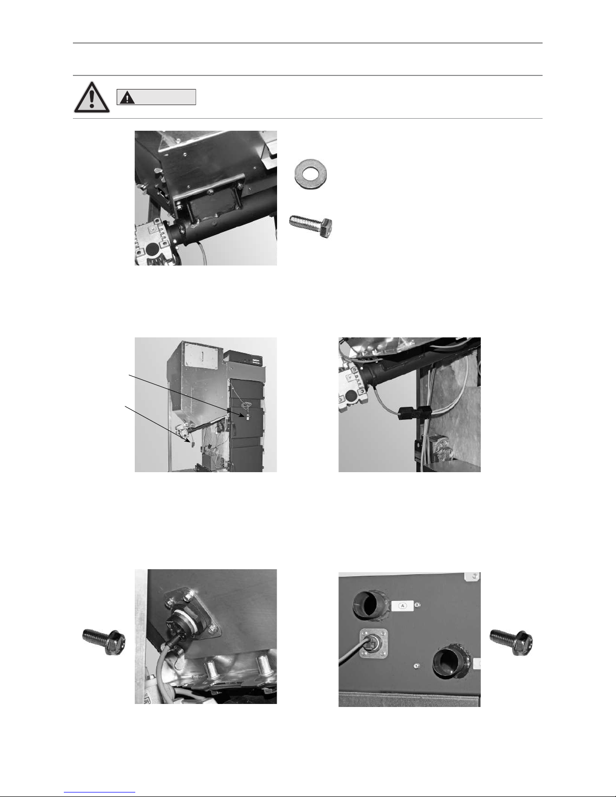
– Screw hopper to auger tube flange plate with 6 x M8 U-washers and 6 hexagon screws (M8 x 25) – Fig. 28.
Fig. 28 Fitting auger with 6 U-washers
and 6 hexagon screws
– Connect auger motor plug (Fig. 29, Fig. 30)
– Mount “empty“ fill level switch on bottom left of hopper with 4 TT screws (M5 x 12) (Fig. 31) and “full“ fill level
switch at top rear of hopper with 4 TT screws (M5 x 12) – Fig. 32.
Fig. 29 Plugs for auger motor
and fill level switch
Fig. 30 Connecting plug for auger motor
Fig. 31 Mounting “empty“ fill level switch on
bottom left of hopper with 4 TT screws
6 each of
U-washer M8
M8 x 25
Empty fill
level switch
Plug for auger
motor
Fig. 32 Mounting “full“ fill level switch to top
rear of hopper with 4 TT screws
4x
M5 x 12
4x
M5 x 12
CAUTION
Ensure tight seal.
Page 24
24
2. For the Installer
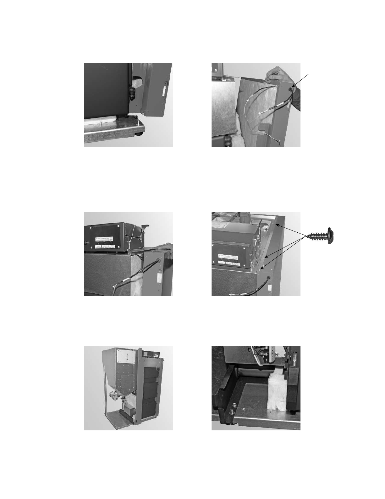
– Fit right side panel (part 4); at bottom, position cut-out in base – Fig. 33.
– Thread InfoWIN
PLUS
cable into side panel as shown in Fig. 34 and press in strain relief.
Fig. 33 Fitting right side panel Fig. 34 Threading InfoWIN
PLUS
cable into side panel
– Fit vertical center panel (part 21) – Fig. 37, remove 2 x prefitted TT screws at bottom – Fig. 38.
Fig. 35 Fitting right side panel – view from below Fig. 36 Threading InfoWIN
PLUS
cable into side panel
Fig. 37 Fitting vertical centre panel
Fig. 38 Removing prefitted TT screw
3x
– Thread InfoWIN
PLUS
cable through opening beside control panel – Fig. 35. For connection in control panel, see
section 3.1.2.
– Secure side panel at top with 3 self-tapping screws – Fig. 36.
Strain relief
Page 25
25
2. For the Installer
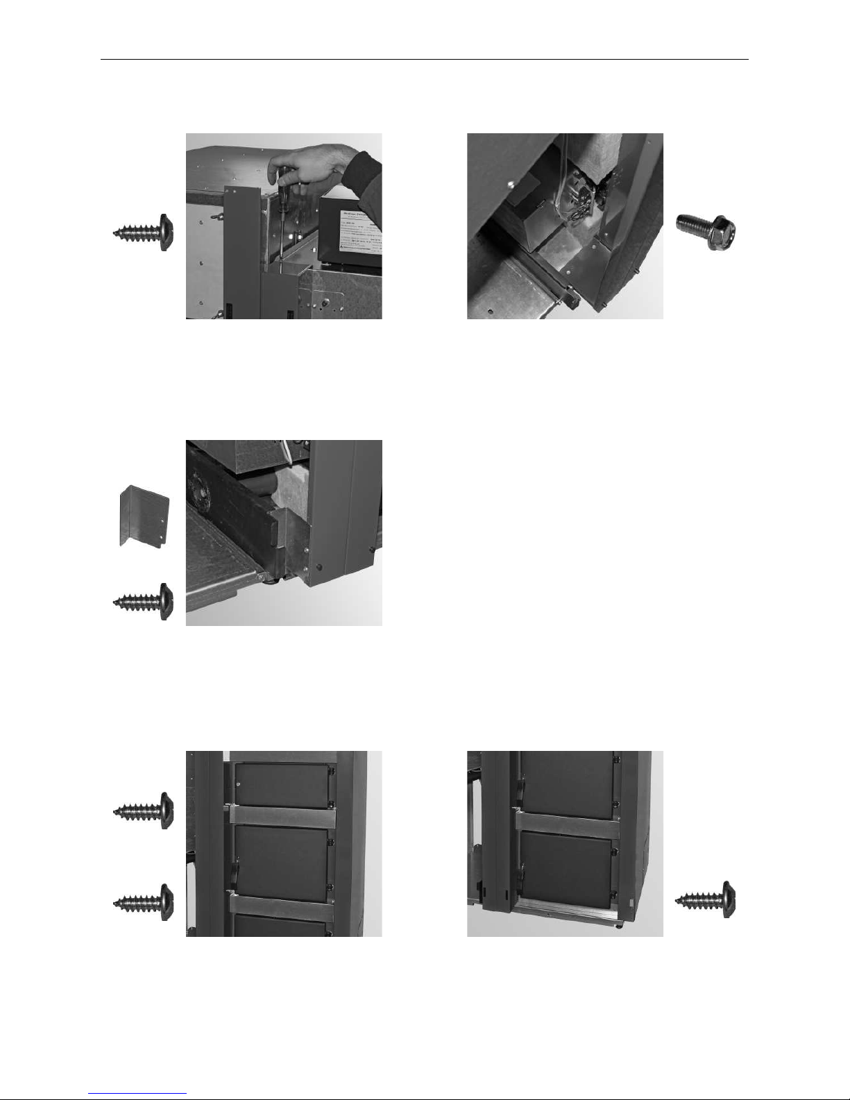
– Secure vertical center panel at top with 2 self-tapping screws (Fig. 39) and at bottom with previously removed
2 TT screws (M5 x 12) – Fig. 40.
Fig. 39 Securing center panel at top
with 2 self-tapping screws
– Fit hand guard bracket (part 22); fasten to vertical center panel with 2 self-tapping screws – Fig. 41.
– Fit horizontal center panels (part 10); secure each panel with 4 self-tapping screws – Fig. 42.
– Mount base panel (part 9) with 2 self-tapping screws – Fig. 43.
Fig. 40 Securing center panel at
bottom with 2 TT screws
2 x 2x
M5 x 12
Fig. 41 Fit hand guard bracket with
2 self-tapping screws
2 x
1 x
4x 2x
Fig. 42 Securing both centre panels with
4 self-tapping screws each
Fig. 43 Securing base panel with 2
selftapping screws
4x
Page 26
26
2. For the Installer
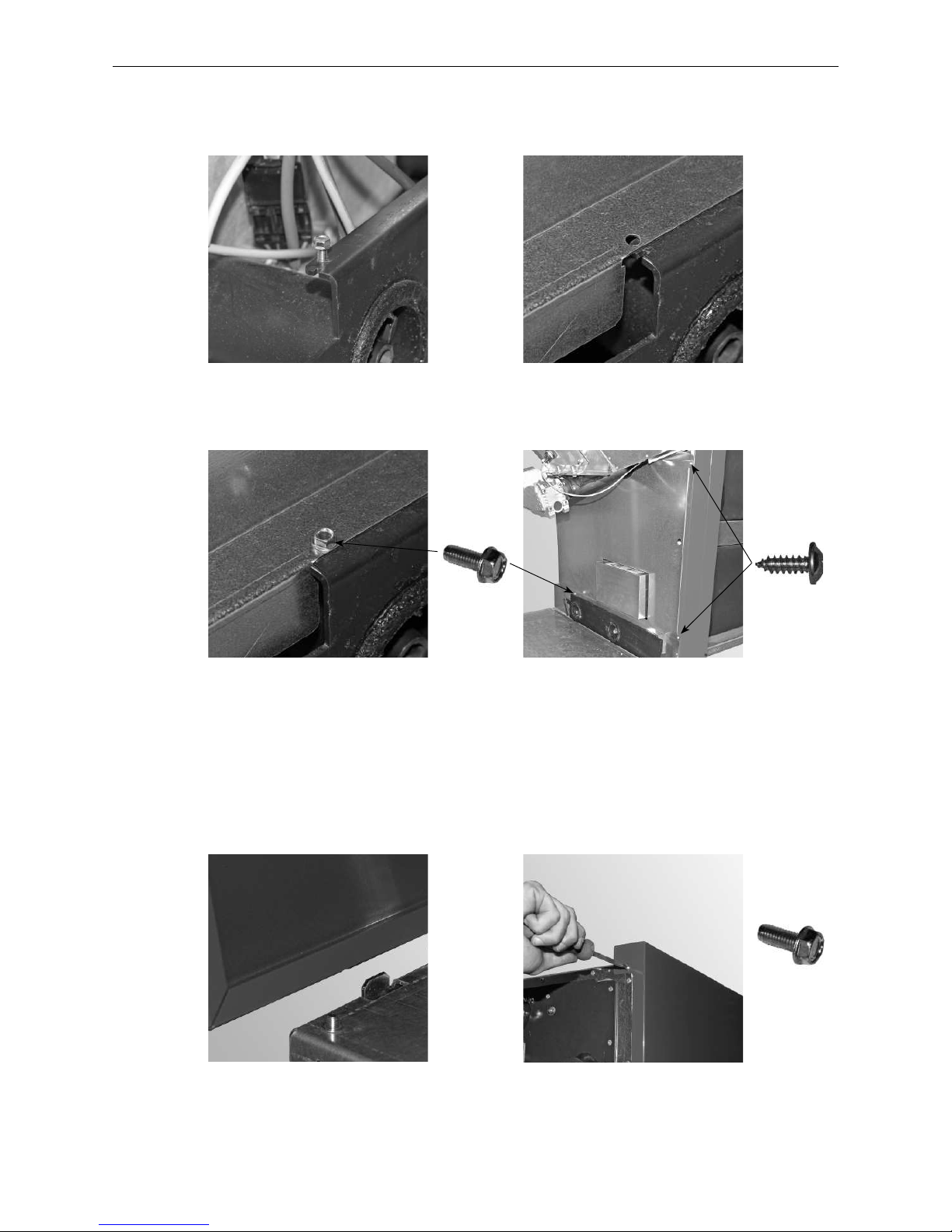
– Remove prefitted TT screw at rear – Fig. 44. Slide side anti-contact protection plate (part 23) into guide slot
from the back (Fig. 45) and secure with the previously removed TT screw (M5 x 12) (Fig. 46) and 2 self-tapping
screws at the front – Fig. 47.
Fig. 44 Removing prefitted TT screw Fig. 45 Sliding anti-contact protection
plate into guide slot
– Fit left side panel (part 18); at bottom, position cut-out in base – Fig. 48.
– Secure side panel to the hopper at the top rear using 1 prefitted TT screw (M5 x 12) – Fig. 49.
Fig. 46 Securing anti-contact protection
plate with TT screw
Fig. 47 Attaching anti-contact protection plate
at front with 2 self-tapping screws
Fig. 48 Fitting left side panel
Fig. 49 Securing left side panel to hopper
at top rear with 1 TT screw
2x1x
M5 x 12
1x
M5 x 12
Page 27
27
2. For the Installer
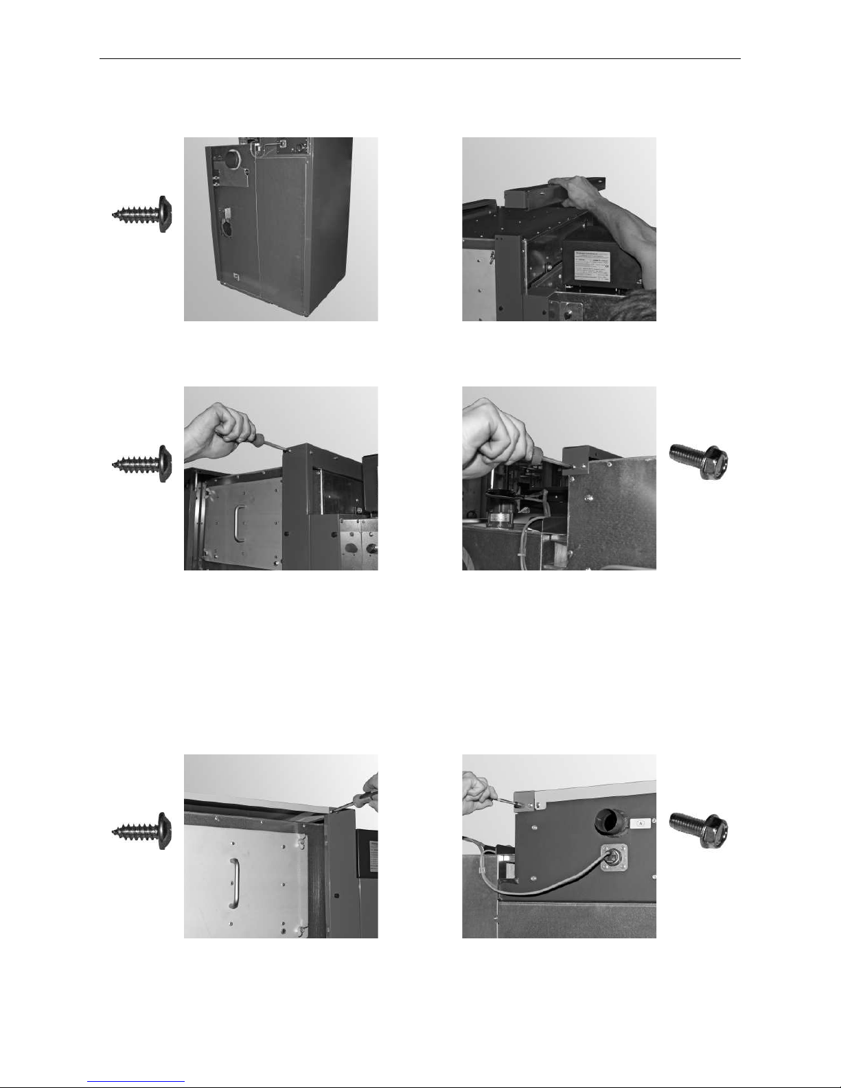
– Fit rear wall (part 1); secure with 4 self-tapping screws – Fig. 50.
– Fit hopper cladding at top right (part 21) – Fig. 51; secure at front and side with 1 self-tapping screw in each
case (Fig. 52) and secure at rear with 2 prefitted TT screws (M5 x 12) – Fig. 53.
Fig. 50 Securing rear wall with 4
selftapping screws
Fig. 51 Mounting hopper cladding
at top right
– Fit cover of integral fuel hopper (part 20); secure with 2 self-tapping screws at front (Fig. 54) and secure at rear
with 2 prefitted TT screws (M5 x 12) – Fig. 55.
Fig. 52 Securing hopper cladding at front
and side with self-tapping screws
Fig. 53 Securing rear hopper cladding
with 2 TT screws
Fig. 54 Securing cover of integral fuel hopper
at front with 2 self-tapping screws
Fig. 55 Securing reserve supply container
cover at rear with 2 TT screws
4x
2x
2x
2x
M5 x 12
2x
M5 x 12
Page 28
28
2. For the Installer
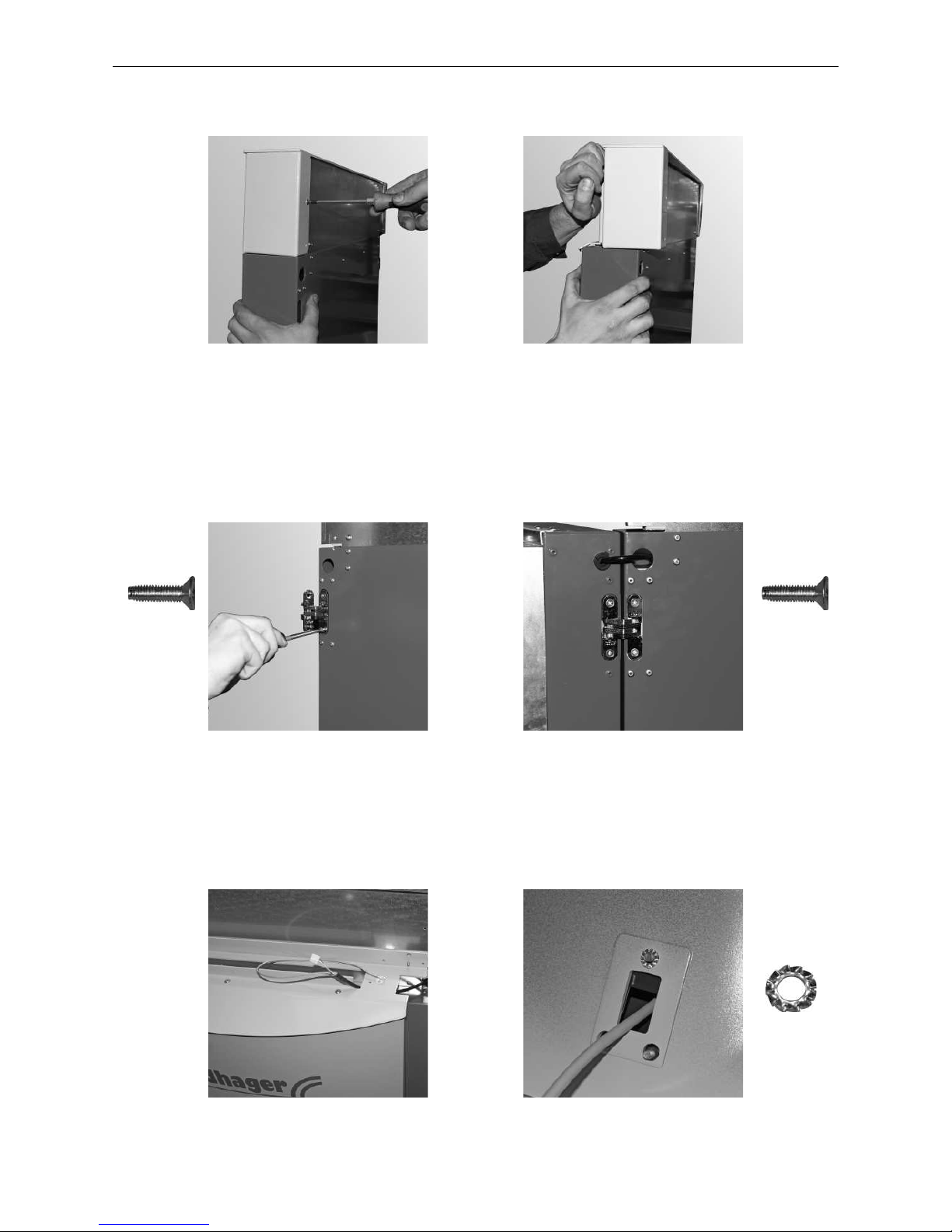
– Remove cladding door cover (part 6) from cladding door; remove 4 self-tapping screws (Fig. 56), push cover
back and lift – Fig. 57.
Fig. 56 Demounting cladding door cover –
removing screws
Fig. 57 Removing cladding door cover
– Thread InfoWIN
PLUS
cable into door – Fig. 60.
– Mount InfoWIN
PLUS
(part 8) on cladding door cover (part 6) with a saw tooth ring for grounding (Fig. 61) and
3 nuts – Fig. 62.
Fig. 58 Fitting both hinges on cladding door Fig. 59 Mounting cladding door with
hinges on right side panel
Fig. 60 Threading InfoWIN
PLUS
cable into
door
Fig. 61 Fit saw tooth ring under one nut –
grounding
– Fit both door hinges (part 5) top and bottom in cladding door (part 9) with 2 countersunk screws each – Fig. 58.
– Mount cladding door (part 9) with hinges on right side panel (part 4) using 2 countersunk screws, and insert
InfoWIN
PLUS
cable through opening – Fig. 59.
2x
M4 x 16
2x
M4 x 16
1x
Page 29
29
2. For the Installer
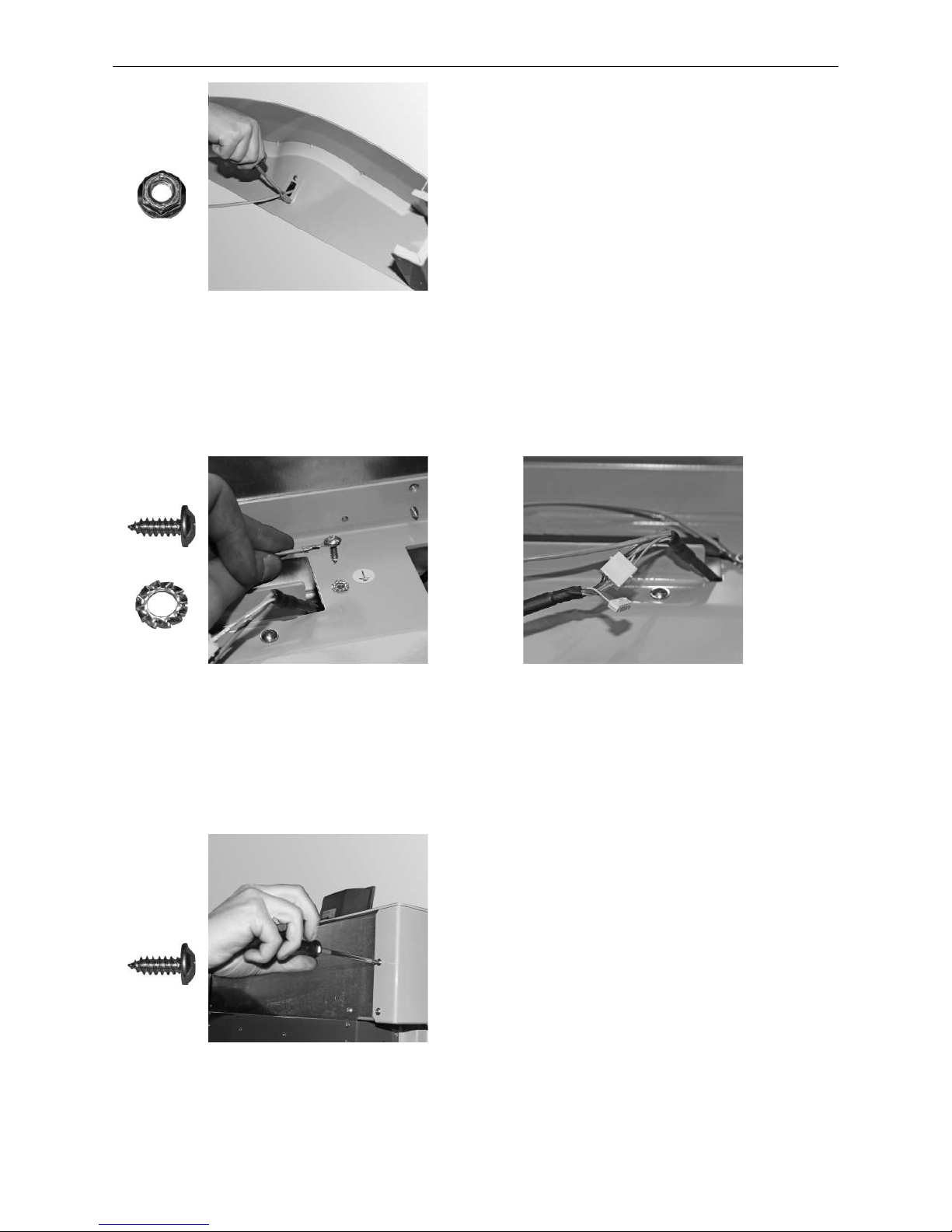
Fig. 62 Mounting InfoWIN
PLUS
on cladding
door cover
– Mount cladding door cover on door again with 4 self-tapping screws – Fig. 65.
Fig. 63 Attaching grounding cables and
saw tooth ring to cover
Fig. 64 Connecting InfoWIN
PLUS
plug and at-
taching grounding cables
Fig. 65 Reattaching the cladding door cover
– Screw grounding cables to cover (with saw tooth ring between cover and ground) (Fig. 63) and connect 4-pin
plug for InfoWIN
PLUS
cable (5-pin plug remains unconnected)– Fig. 64.
1x
+
4x
3x
Page 30
30
2. For the Installer
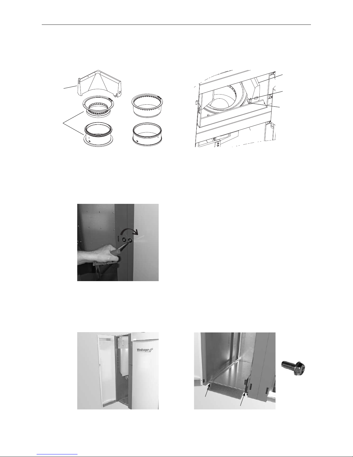
– Place the cone in the burner pot – Fig. 66.
– Fit the ash wedge (BioWIN XL 350 NA only) on the burner pot in the right-hand corner, making sure the limit
stop is behind the screw head – Fig. 67.
Fig. 66 Fit cone and ash wedge (with BioWIN XL
350 NA only) in / on burner pot.
Fig. 67 Fit cone and ash wedge (with BioWIN
XL 350 NA only) in / on burner pot.
– Mount left cladding door (part 12) on integral fuel hopper – Fig. 69.
– Attach access ramp (part 14) for ash container with 2 prefitted TT screws (M5 x 12) – Fig. 70.
Fig. 68 Closing the cladding door and
locking with the key
Fig. 69 Fitting left cladding door
Fig. 70 Attaching access ramp with 2
TT screws (M5 x 12)
– Close cladding door and turn key a quarter turn to the right to lock – Fig. 68.
Ash wedge
Limit stop
Screw head
BioWIN XL 350 NA BioWIN XL 450 NA / 600 NA
Ash wedge
Cone
2x
M5 x 12
Page 31
31
2. For the Installer
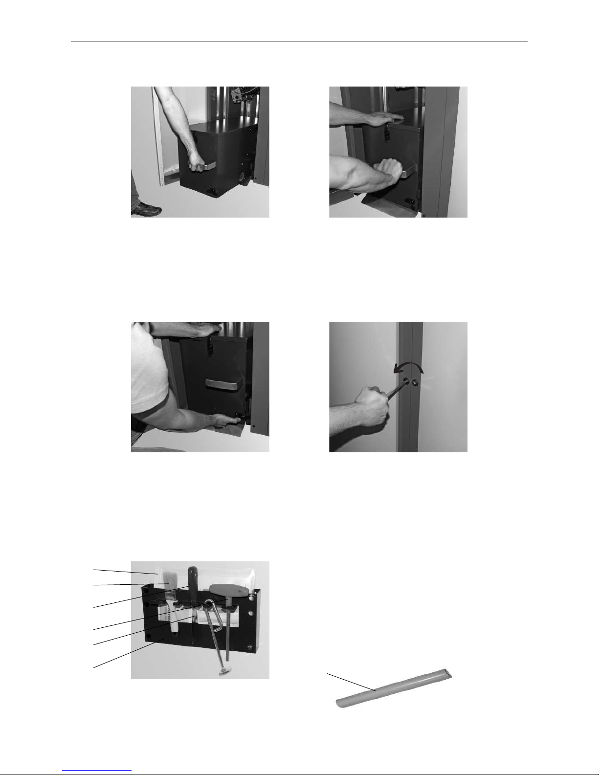
– Slide in the ash container – Fig. 71.
– Push the ash container slightly to the right and slide the handle all the way in – Fig. 72.
Fig. 71 Sliding in the ash container Fig. 72 Pressing the container slightly to the
right and sliding the handle all the way in
– Install the hanger with the instructions folder and cleaning and operating implements on a wall in the boiler
room – Fig. 75.
Fig. 73 Closing the bracket fastener Fig. 74 Closing the cladding door with the key
– Closing the bracket fastener – Fig. 73.
– Close left cladding door and turn key a quarter turn to the left to lock – Fig. 74.
Supplied as standard:
1 ...........Folder containing instructions
2 ...........Cleaning brush
3 ...........Spatula
4 ...........Key
5 ...........Down chute cleaning tool
6 ...........Hanger (for installation on the wall)
7 ...........Suction tube for cleaning the primary air tube
in the burner pot
Fig. 75 Mounting hanger with instructions folder,
cleaning and operating implements
1
2
3
4
5
6
7
Page 32
32
2. For the Installer
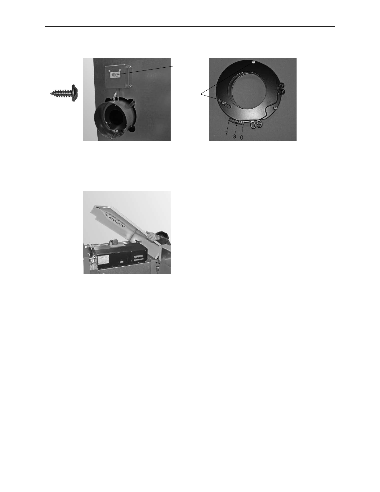
- Mount intake fitting (part 3) on rear of boiler with 4 self-tapping screws and connect both pressure hoses –
Fig. 76. Set the orifice in the intake fitting to the value set on the sticker (0–7). To do this, unfasten 2 screws,
turn the orifice (orifice fully open = 0) and retighten the screws – Fig. 77.
Fig. 76 Mounting the intake fitting Fig. 77 Setting the orifice in the intake
fitting to the value on the sticker
– Fit cladding cover (part 2) – Fig. 78.
For installation of the hoses and installation notes, see section 2.11.
Fig. 78 Fitting the cladding cover
4x
Sticker with factory setting
Loosen 2
screws, turn
orifice
Page 33
33
2. For the Installer
2.8 Installing the exhaust pipe
a) Install the exhaust pipe upward to the flue (45° is the ideal angle). Maximum exhaust pipe length 9.8 ft / 3 m.
b) Avoid 90° bends, 45° bends are better
c) Make the flue connection at 45° if possible.
d) Do not push the exhaust pipe too far into the flue.
e) Do not seal the exhaust pipe completely into the flue. Connection with flexible exhaust pipe inlet into the flue.
The Induced draught fan can cause sound transmissions that create noise pollution.
f) The BioWIN XL is a low-pressure boiler and this means that the flue gas system needs to meet the „N1“ seal
integrity requirement according to EN 1856-1 and EN1856-2. Please ensure a sufficient immersion depth when
fitting (e.g., when using Windhager stainless steel flue systems).
g) The entire exhaust line (particularly after 3.28 ft / 1 m length) should be insulated in order to prevent or
minimise condensation.
INFORMATION
Any section of this exhaust line that is horizontal or inclined less than 30 degrees
cannot be more than 3.28 ft / 1 m in length.
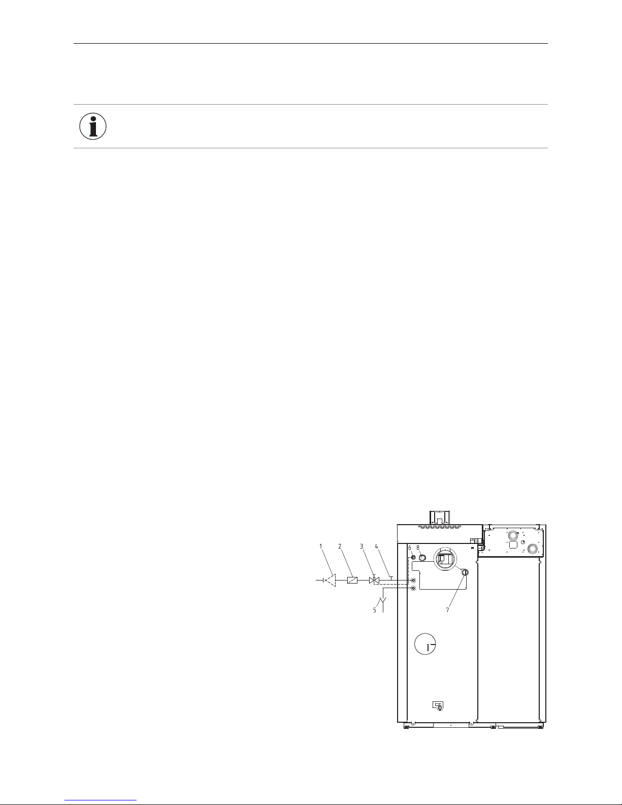
1 ...........Pressure reducing valve (only with CW connection of more
than 6 bar)
2 ...........Dirt trap
3 ...........Thermal discharge safeguard (opens at approx. 203 °F / 95 °C)
4 ...........Cleaning –T-piece
5 ...........Discharge funnel
6 ...........Immersion sleeve for the sensor of the thermal discharge
safeguard
7 ...........Boiler return
8 ...........Boiler feed
2.9 Installing the thermal discharge safeguard
a) The thermal discharge safeguard, non-return valve and cleaning T-piece must still be accessible after installation.
b) The drain must be visible in order to check the function, therefore use a discharge funnel.
c) It must not be possible to block the connection manual.
Connection in accordance with EN 303-5:
Minimum connection pressure of the thermal safety device: 2 bar.
Fig. 79 Thermal safety device connection
Page 34
34
2. For the Installer
2.10 Installation instructions for 3-way changeover unit,
suction probes, suction turbine
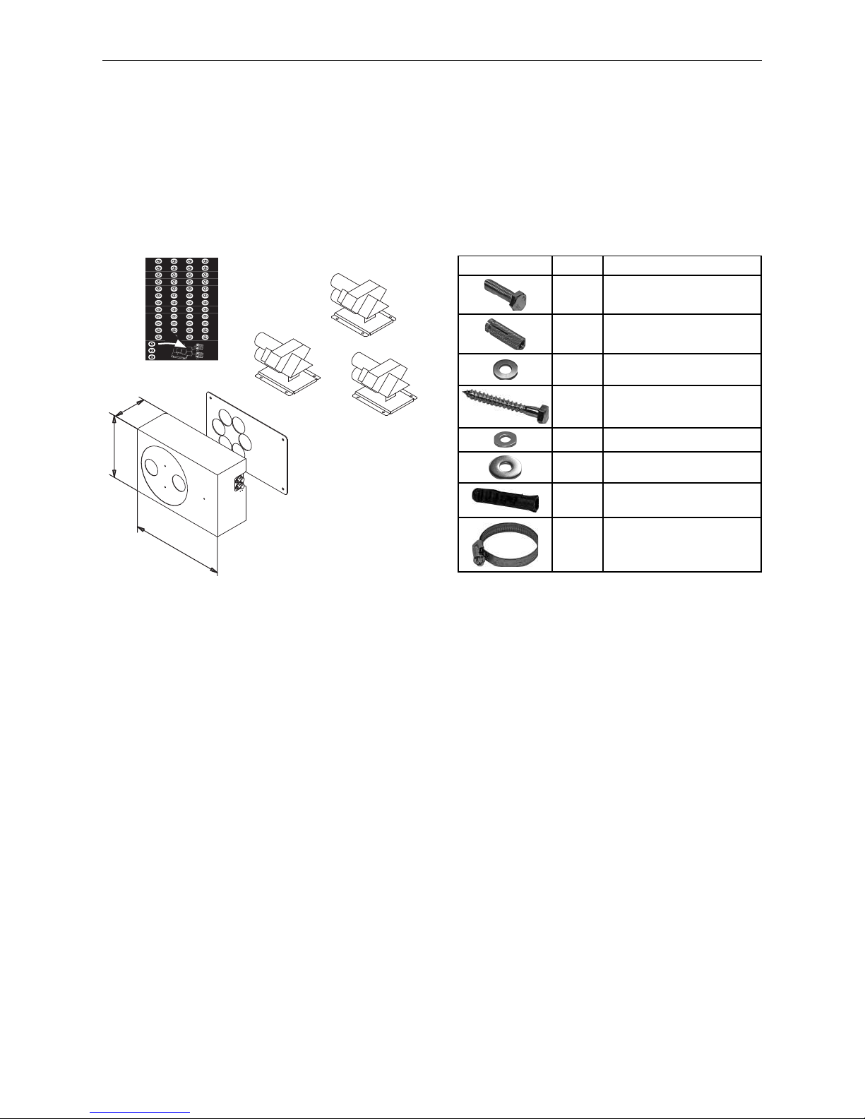
2.10.1 Scope of delivery, packaging
05/2010 007057/01
5.59 in
10.55 in
15.55 in
142 mm
395 mm
268 mm
Fig. 80 Automatic changeover unit with cover plate, 3x suction probes
Part Quantity Designation
4 M8 x 30 hexagon screw
4 M8 x 30 brass dowel
4 U-washers 8
10
6 x 50 hexagon head wood
screws
6 U-washers 6
4
U-washers 6
[large diameter]
10 F8 dowel
8 40–60 hose clip
Automatic changeover unit with cover plate, 3x suction probes – BIO 020
Delivery hose (not shown) with flexible grounding leads, DN 50 – 82 ft / 25 m (supply and return air hoses)
– PMX013
Page 35
35
2. For the Installer
B1
A1
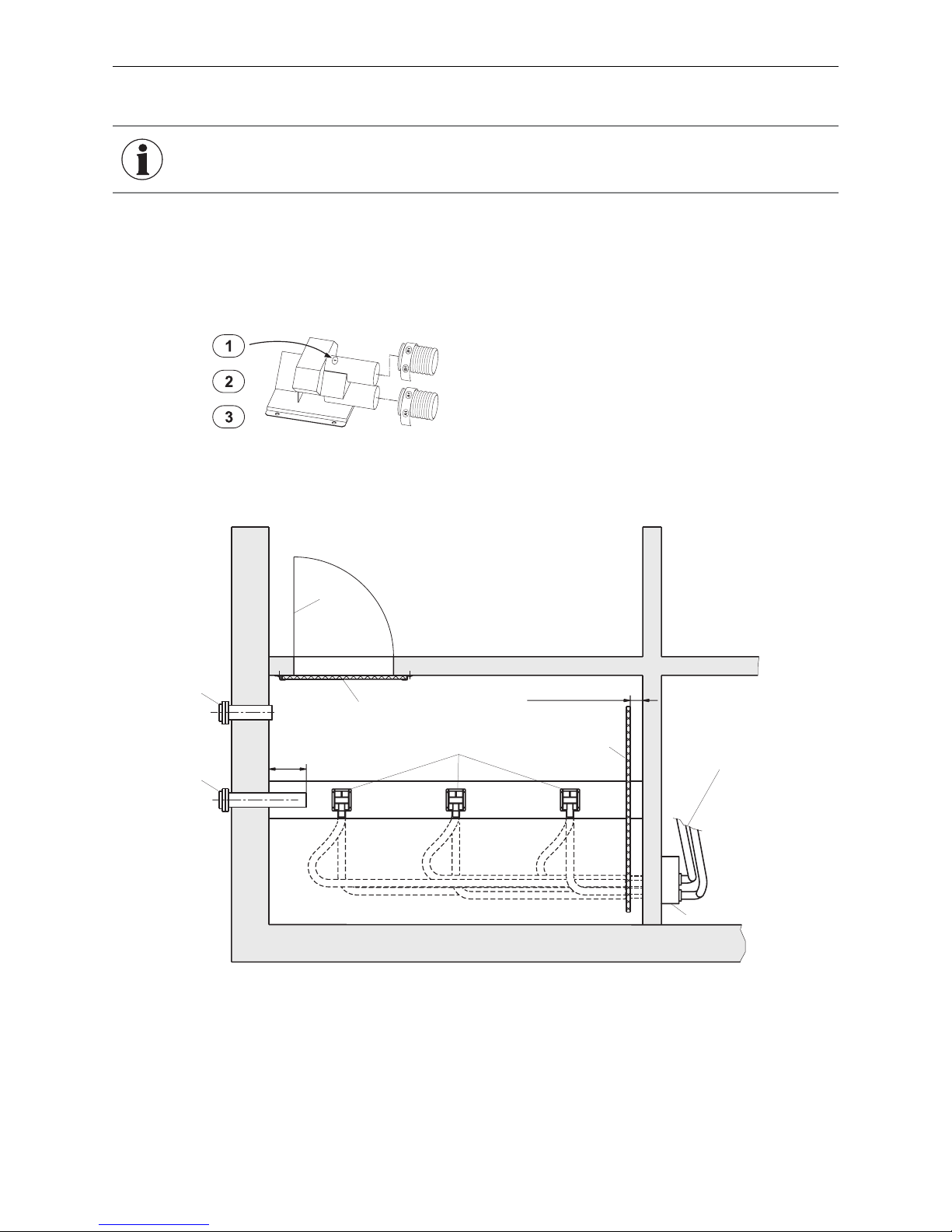
Fig. 81 Suction probe
2.10.2 Notes on installing the suction probes
To achieve even emptying of pellets, arrange the suction probes so they are evenly and appropriately spaced for
the size of the pellet storage room. Affix stickers 1, 2, and 3 to the suction probes – Fig. 81. Bolt the suction probes
onto the floor in sequence – Fig. 82.
B1 ........Return air hose
A1 ........Supply hose
1 ...........Storage room door
2 ...........Wooden boards
3 ...........Suction probes
4 ...........Filling pipe
5 ...........Return air pipe
6 ...........Automatic changeover unit
7 ...........Supply and return air hoses to the pellet boiler/heater or suction turbine
8 ...........Baffle plate
6
1
min. 3.93 in / 10 cm
min. 11.81 in / 30 cm
2
3
4
5
7
8
Fig. 82 Pellet storage room – view from above
INFORMATION
For information on installing the suction probes in a sheet steel tank or fabric tank,
refer to the installation instructions for sheet steel and fabric tanks.
Page 36

36
2. For the Installer
2.10.3 Notes on installing the supply and return air hoses
2.10.3.1 Maximum transport length and height for pellet feed system
Max. distance of 82 ft / 25 m between furthest probe and pellet boiler/heater with max. total height difference of
5.9 ft / 1.8 m
Max. distance of 49.2 ft / 15 m between furthest probe and pellet boiler/heater with max. total height difference
of 9.2 ft / 2.8 m
Max. distance of 32.8 ft / 10 m between furthest probe and pellet boiler/heater with max. total height difference
of 14.8 ft /4.5 m
Total height difference: Sum of lengths of all rising pipes
2.10.3.2 Important moving references for supply and return air hoses
– Do not kink the hoses; the minimum bend radius is 11.81 in / 30 cm.
– Hoses must not be laid in an ”up and down“ manner. This could cause ”bags“ to form, preventing the pellets
from flowing smoothly.
– Use the shortest route from the storage room to the feed unit, and lay the hoses in such a way that they will not
be walked on.
– When connected to the changeover unit, hoses must be long enough to allow the probes to be flushed through
in reverse.
– It is best to lay the hoses in a plastic tube secured with clips.
– The pellet feed hose must consist of a single piece; however, an extra section may be added to the return air
hose outside of the storage room. The connecting piece must be made of metal (accessory: PMX 0131) and
must have a ground connection.
– Hoses must be grounded to prevent static charge during pellet transport.
– Hoses are rated for temperatures up to +140 °F / +60 °C and must not come into contact with non-insulated
heating pipes or the exhaust pipe.
– Hoses must not be routed outdoors as UV rays will make them brittle.
Page 37
37
2. For the Installer
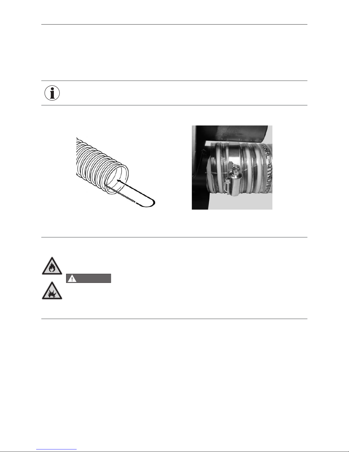
Fig. 83 Bending flexible grounding leads
inward into the hose.
Fig. 84 Fitting the hose clips
2.10.3.3 Installing the supply and return air hoses
– Expose approx. 1.97 in / 5 cm of the flexible grounding leads on all hose ends, and bend inwards into the hose
– Fig. 83.
– Slide hose clips over the hose and plug into connectors. The grounding wire must have good contact with the
connectors. If necessary, file down the coating on the pipe. Tighten the hose clips – Fig. 84.
INFORMATION
If you have problems making a connection, dampen the connections with water
(do not use grease).
DANGER
Pellet feed unit: fire and explosion hazard
Can lead to serious injury/death! Ground suction hoses must be installed as described in the installation instructions at every connection to avoid static sparking/
dust ignition. The pellet feed unit is for use with the day hopper only. The feed unit
must be braced, anchored, or strapped to avoid falling/shifting during an earthquake. Instructions can be obtained from your local Windhager dealer or wholesaler.
Pellet feed automatic changeover unit: Fire and explosion hazard
Fire and explosion hazard can lead to serious injury or death.
Do not use the pellet feed automatic changeover unit inside pellet storage room
or where there is a lot of dust present. Connect delivery hoses to pellet feed automatic changeover unit as described in the installation instructions to avoid static
sparking or dust ignition.
Page 38
38
2. For the Installer
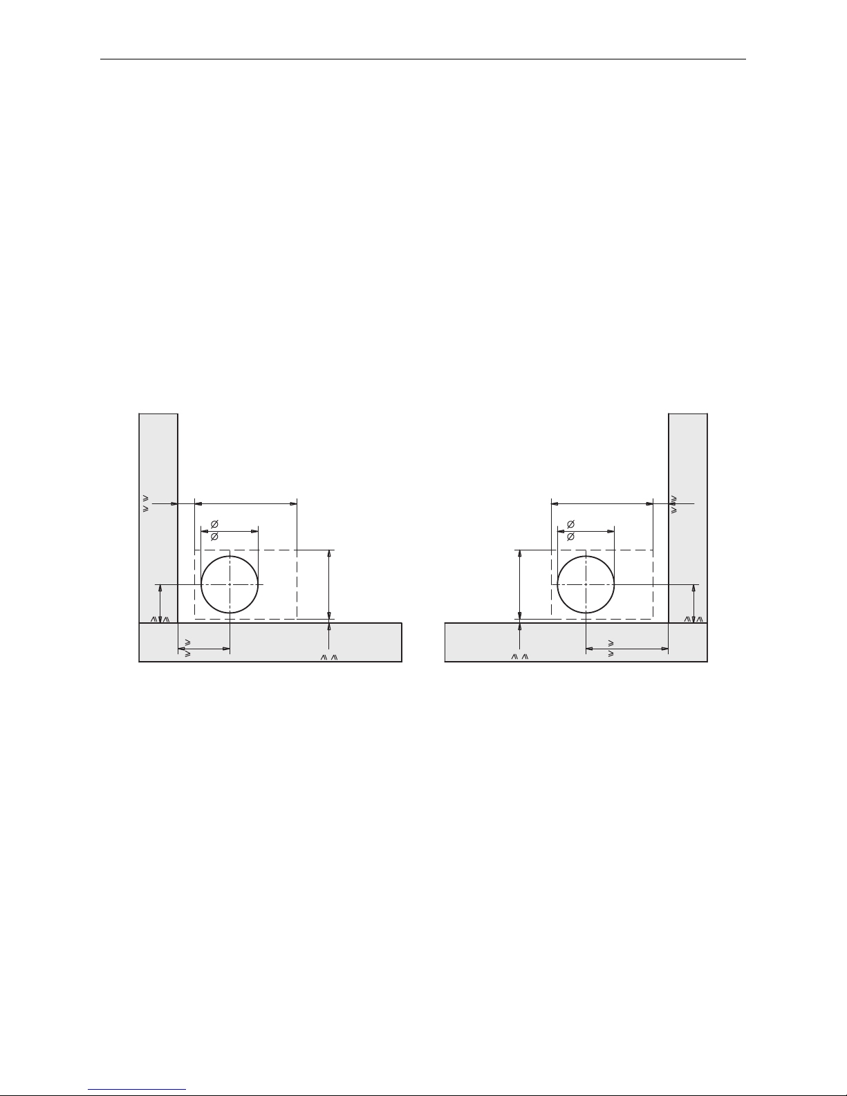
15.55 in
395 mm
2.32 in
59 mm
2.6 in
66 mm
8.66 in
220 mm
10.55 in
268 mm
5.9 in
150 mm
0.63 in
16 mm
12.6 in
320 mm
7.87 in
200 mm
5.9 in
150 mm
8.66 in
220 mm
15.55 in
395 mm
10.55 in
268 mm
0.63 in
16 mm
Fig. 85 Feed-through for changeover unit on left- or right-hand wall – front view
2.10.4.1 Masonry feed-through
The changeover unit should be attached with the brass dowels provided. If it cannot be securely attached in the
masonry with the brass dowels, a fire-protection tested injection system must be used to attach the changeover
unit.
Wall duct for changeover unit
Make a feed-through hole approx. 8.66 in / 220 mm in diameter for the changeover unit (Fig. 85).
All dimensions in inch / mm:
2.10.4 Notes on installing the changeover unit
Some states/cities may require a fire stop between the bulk wood pellet hopper (main wood pellet storage) and
the room where the appliance is installed (mechanical room). If your state/city requires this, follow your local
building codes to install a proper fire stop. The changover unit is not a fire stop and does not fulfill the requirements of a fire stop to separate different fire zones.
Page 39
39
2. For the Installer
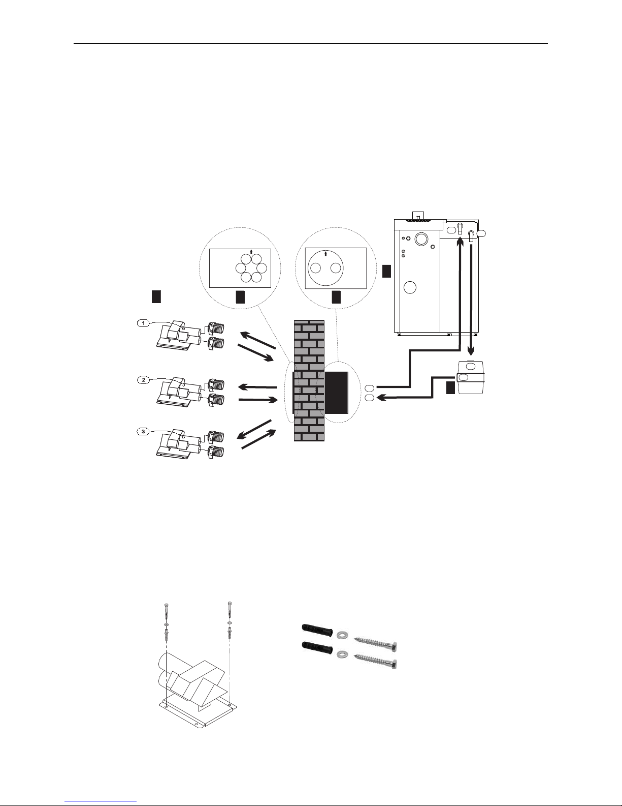
2.10.5 Installation 3-way changeover unit, suction probes
Path of pellets
The pellets move from probes A1, A2, and A3 through the corresponding cover plate holes A1, A2, and A3, to the
rear of the changeover unit (A). They then pass through the front of the changeover unit (A) to the pellet boiler (A).
Path of return air
The return air follows a path from the pellet boiler (C) to the suction turbine (C) and from the suction turbine (B)
to the front of the changeover unit (B). It then passes from the rear of the changeover unit B1, B2, and B3, back to
the probes B1, B2, and B3.
Overview of connection to the BioWIN XL
B1
B2
B3
A3
A2
A1
B
A
1
2
3
B1
A1
B2
A2
2
B2
A2
3
B
C
4
B
A
A
C
5
Fig. 86 Overview of connections
1 ...........Suction probes
2 ...........Cover plate
3 ...........Changeover unit
4 ...........Suction turbine
5 ...........BioWIN XL
2.10.5.1 Installation sequence
1. Fit suction probes on storage room floor
– Drill 2 fastening holes 0.31 inch / 8 mm in diameter for each suction probe.
– Insert F8 dowel.
– Fasten each probe to the floor with two 6x50 hexagon head wood screws and U-washers – Fig. 87.
6 x 50
Fig. 87 Fitting a suction probe
Page 40
40
2. For the Installer
3. Trim delivery hose to correct length and route through the storage room
– Expose approx. 1.97 in / 5 cm of the flexible ground lead on the hose end, and bend it inwards into the hose.
Label with sticker A1 – Fig. 89.
– Insert hose end through opening A1 in cover plate, until it is flush with the wall on the outside – Fig. 90.
– Route hose through the storage room to probe connection A1. Trim, expose ground wire, and label with A1
(minimum bend radius 11.81 in / 30 cm). Do not attach hose to probe at this time. Proceed in the same way for
all other hoses: A2, A3, B1, B2 and B3.
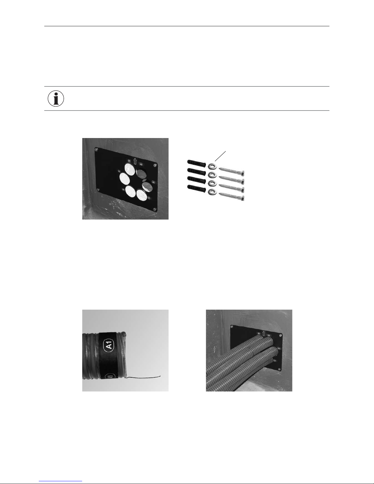
2. Fit cover plate inside storage room
– Drill 4 mounting holes 0.31 inch / 8 mm in diameter.
– Insert 4 x F8 screw anchors
– Temporarily screw down the cover plate with four 6 x 50 hexagon head wood screws and U-washers 6 [large
diameter] – Fig. 88.
Fig. 88 Temporarily fitting cover plate
Fig. 89 Exposing flexible ground leads,
exposing ground wire, sticking on label
Fig. 90 Inserting hoses – storage room side
U-washer with large diameter
INFORMATION
The cover plate can be used to mark the drill holes for the changeover unit and
cover plate. The cover plate and changeover unit must be correctly aligned - the
arrows on each must point in the same direction (e.g., both arrows pointing up).
Page 41
41
2. For the Installer
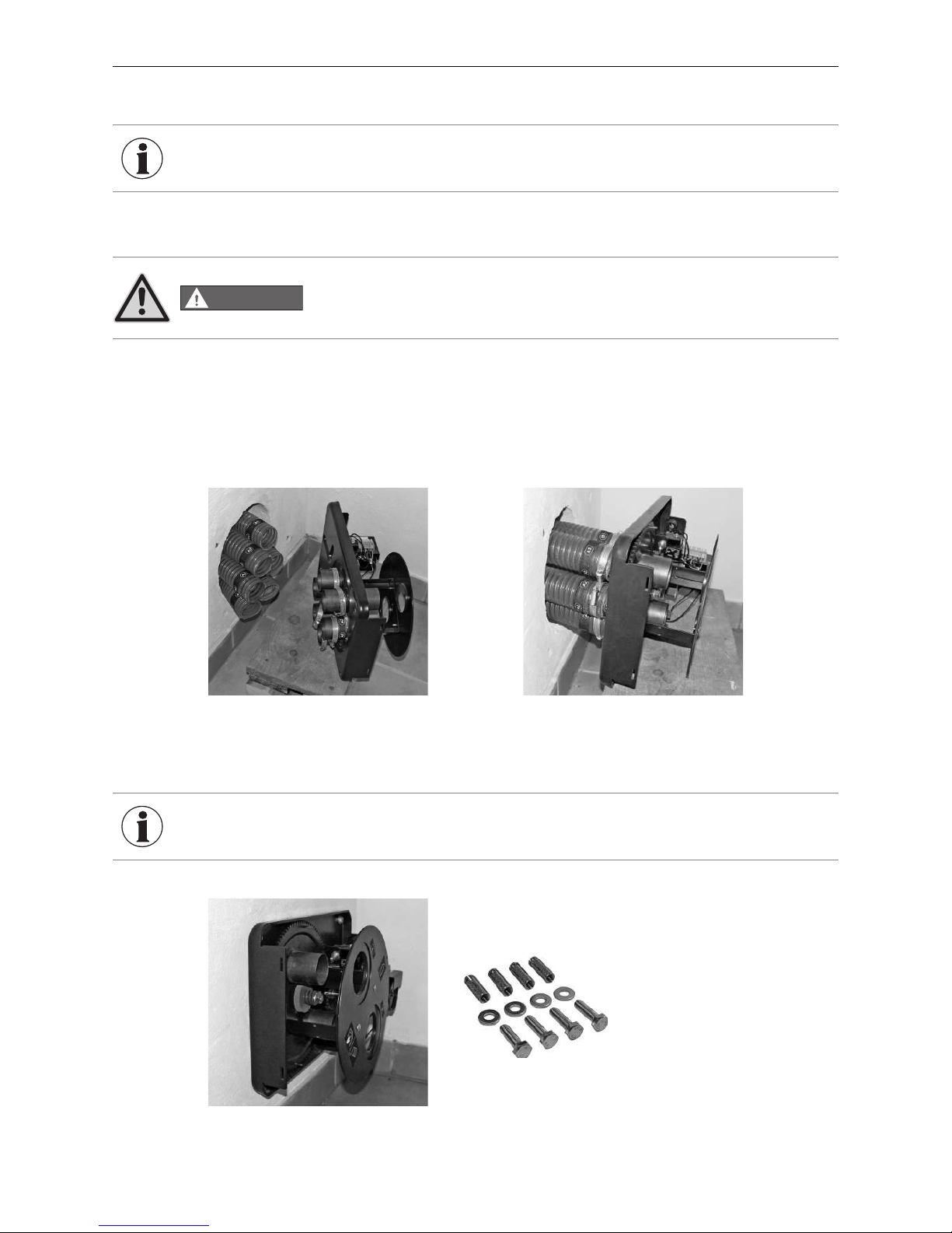
4. Mounting the changeover unit
– Drill holes for metal dowels 0.39 inch / 10 mm in diameter and insert brass dowels.
Fig. 91 Attaching hose clips Fig. 92 Securing hoses with hose clips
– Screw down the changeover unit with four M8 x 30 hexagon screws and U-washers – Fig. 93.
Fig. 93 Screwing down changeover unit
– Remove the changeover unit cover (1 screw at front), and slide the hose clips over the changeover unit connec-
tors – Fig. 91.
– Connect the labeled hoses to their corresponding connections on the changeover unit. The flexible ground
leads must be in contact with their connections. Secure the hoses with hose clips – Fig. 92.
INFORMATION
To make fitting the hoses easier, the changeover unit should be at the same height
as the hoses (wooden boards or similar items can be laid underneath).
DANGER
Please note!
The changeover unit should be attached only with the brass dowels provided. If it cannot be securely attached in the masonry with the brass dowels, a fire-protection tes-
ted injection system must be used to attach the changeover unit.
INFORMATION
If necessary, slightly pre-position the brass anchor by starting to insert the hexagon screws.
Page 42
42
2. For the Installer
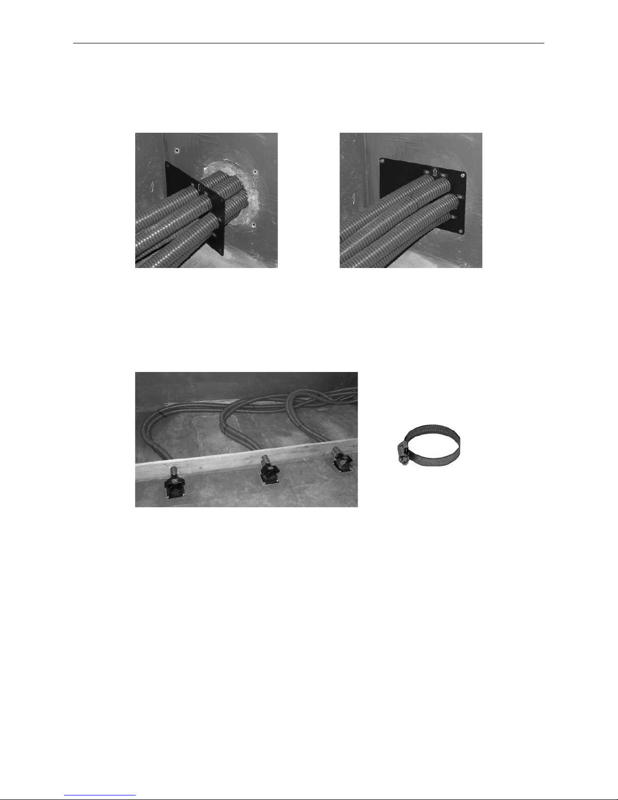
5. Fill masonry feed-through with mineral wool
– Unscrew the cover plate in the storage room, and fill the masonry feed-through with mineral wool – Fig. 94.
– Securely screw down the cover plate inside the storage room – Fig. 95.
Fig. 94 Filling masonry feed-through with
mineral wool
Fig. 95 Fitting the cover disc
6. Connect delivery hoses to probes
Connect the labeled hoses to their corresponding probe connections. The flexible ground leads must be in
contact with their connections. Secure the hoses with hose clips – Fig. 96.
Fig. 96 Connecting the probes
6 x
Page 43
43
2. For the Installer
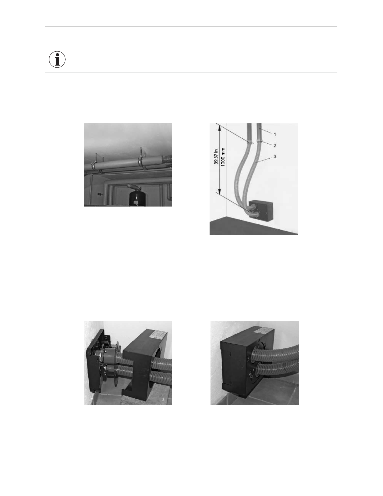
7. Trim the delivery hose to the appropriate length and lay inside plastic tubes
– The hoses must be long enough at the changeover unit end, and must not be tightly fixed (hoses turn 180°).
Maintain the required distance and hose length from the first fastening point – Fig. 98.
– Trim the delivery hose, expose grounding wire, route, and label on both sides with supplied sticker A or B.
Fig. 97 Delivery hoses in plastic tubes
Fig. 98 Connection of changeover unit
1 ...........31.5 in / 80mm plastic tubes
2 ...........Do not clamp hoses tightly
3 ...........There must be at least 4.76 ft / 1450 mm of hose
before the first fastening point
8. Connect delivery hose to changeover unit
– Connect the labeled hoses to their corresponding connections on the changeover unit. The flexible ground
leads must be in contact with their connections. Secure the hoses with hose clips – Fig. 99.
– Fit cover – Fig. 100.
Fig. 99 Securing hoses with hose clips Fig. 100 Fitting cover
INFORMATION We recommend that the hoses be laid in plastic tubes secured with clips – Fig. 97.
Page 44
44
2. For the Installer
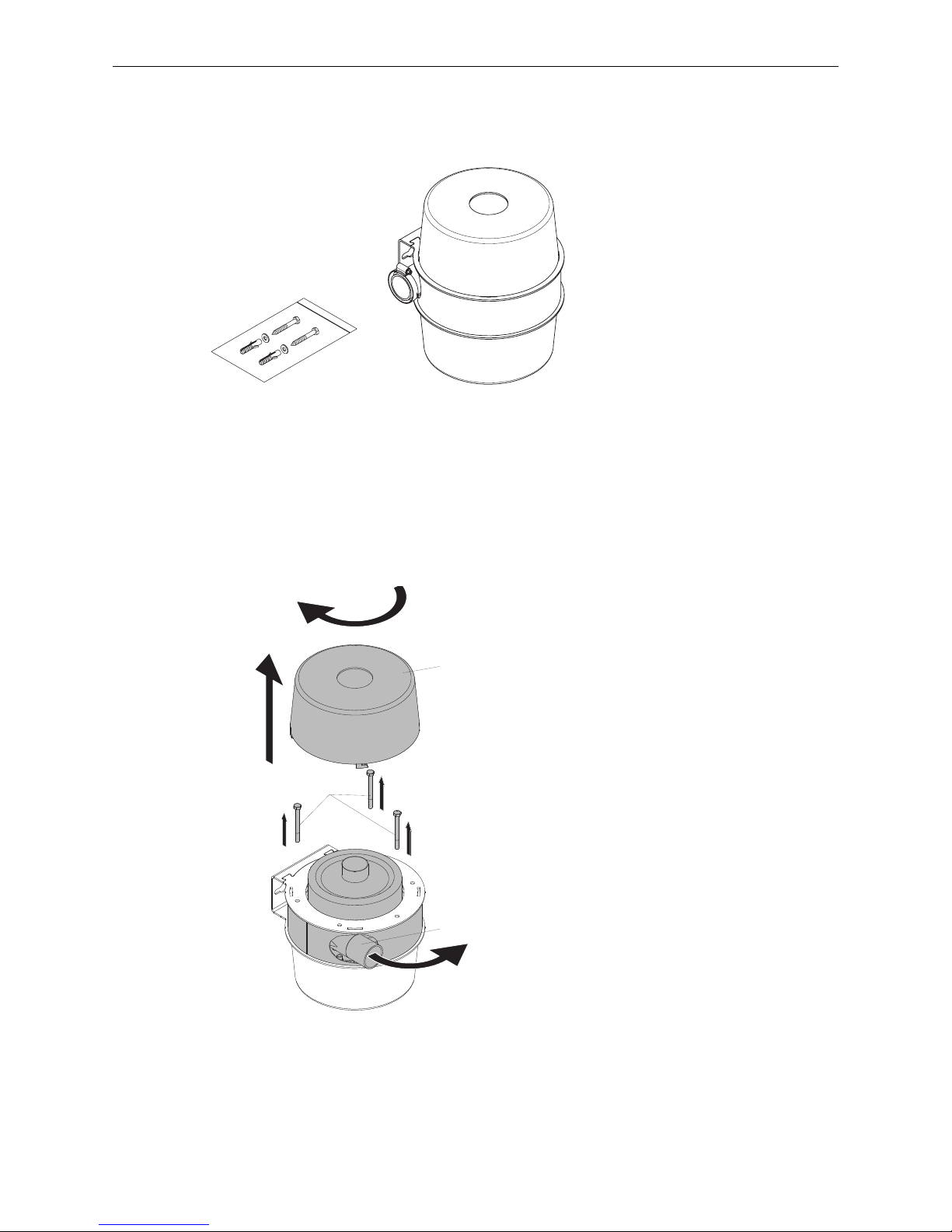
2.10.6 Installation suction turbine
2.10.6.1 Scope of supply
Fig. 101 Suction turbine with installation accessories
1x ........suction turbine
2x ........screws 8 x 60
2x ........U-washer 8
2x ........dowel 10
2.10.6.2 Suction turbine
The hose connection (3) to the changeover unit can be turned through up to 180° to the other side. To do this, rotate the top cover (1) clockwise and lift up and off. Remove 3 screws (2), rotate the hose connection (3) to the desired
position and fix in place again with screws.
1
3
2
Fig. 102 Rotating the hose connection
Page 45
45
2. For the Installer
2.10.6.3 Installation sequence
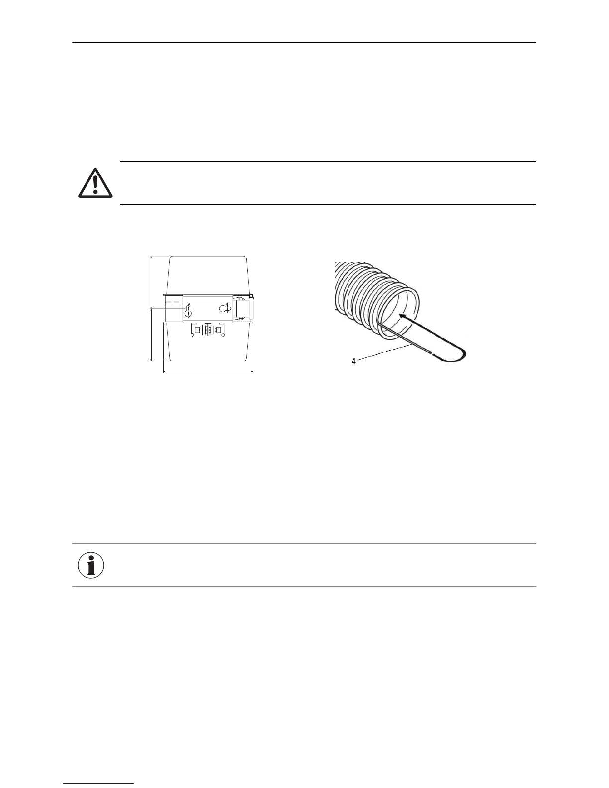
The suction turbine must be in the same room as the pellet boiler. The distance between the BioWIN XL and the
suction turbine must not exceed 9.8 ft / 3 m.
1. Drill 2 holes in the masonry as shown in Fig. 103.
2. Insert screws with U-washer and dowel, leaving approx. 0.39 inch / 10 mm protruding.
3. Attach suction turbine and tighten screws.
Attention!
The suction turbine must be installed with the upwards return air hose connection. The opening for
the bottom cover must remain unobstructed to provide cooling.
4. Expose approx. 1.97 in / 5 cm of the flexible earth leads (4) on all hose ends and bend inwards into the hose –
Fig. 104.
6.3 in
160 mm
6.3 in
160 mm
4.65 in / 118 mm
10.3 in / 270 mm
Fig. 103 Dimensional drawing of
suction turbine
Fig. 104 Exposing flexible earth leads,
bending inwards
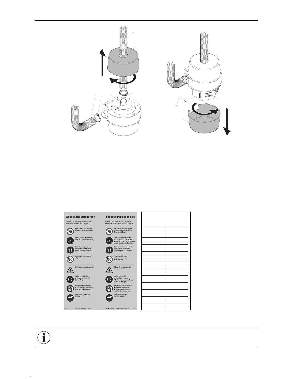
5. Rotate the top cover (2) clockwise and lift up and off – Fig. 105.
6. Slide hose clips (3) and top cover (2) over the hose (1) and plug into connectors. The flexible earth leads (4) of
the hoses and suction turbine must have good contact with the connections. Tighten the hose clips (3). Fit top
cover (2).
7. Make the electrical connection with the pellet boiler and changeover unit:
Remove 2 screws (5) from back of bottom cover (6), turn bottom cover (6) anti-clockwise and pull down and off –
Fig. 106. Connect cables to strain reliefs and connection terminals (7) – for connection diagram, see section6.
8. Fit bottom cover (5).
INFORMATION We recommend a 110–230 V AC cable: 3 x AWG 15.
Page 46
46
2. For the Installer
1
2
3
4
3
1
Fig. 105 Connecting the delivery and return hoses
5
7
6
Fig. 106 Making the electrical connection
2.10.7 Affixing stickers
Affix the enclosed yellow ”Wood pellet storage room“ sticker and white ”Filling date and volume“ sticker on the
pellet storage room door. Every time the storage room is filled, record the date and volume on the ”Filling date
and volume“ sticker.
Fig. 107 Stickers for storage room door
Befüllung Lagerraum
Filling date and volume
Remplissage du silo de stockage
Datum/Date/Date
Menge/Volume/Quantité
kg
kg
kg
kg
kg
kg
kg
kg
kg
kg
kg
kg
kg
kg
kg
kg
kg
kg
kg
kg
kg
kg
kg
INFORMATION
On the outside of the pellet storage room, add labels to indicate where probes 1, 2,
and 3 are located in the storage room.
Page 47

47
2. For the Installer
2.11 Initial commissioning and operating instructions
A Windhager representative or one of its partners must commission your new Windhager boiler system. Our
representatives will ensure that all systems are thoroughly checked and can provide additional information at the
time of commissioning. Installation and routine maintenance performed by a qualified Windhager representative
will ensure the optimal performance and service life of your boiler system. This will also ensure that this technologically advanced system provides the benefits of safe, environmentally friendly, and energy-saving operation.
The following preconditions must be met before ordering the commissioning:
1.) Boiler installed correctly.
2.) System fully electrically wired.
3.) System rinsed, filled, and vented – heat consumption must be possible.
4.) Boiler must be properly connected to the heating system and filled with water.
5.) Sufficient quantity of fuel available (pellets).
6.) The customer and the user must be present during commissioning of boiler.
The commissioning cannot be carried out if any of these items are incomplete or neglected. The customer will
be charged for any unnecessary costs arising as a result.
Commissioning and maintenance by Windhager Customer Service or a customer service partner are part of
the guarantee requirements of the enclosed “guarantee limitations”.
Page 48
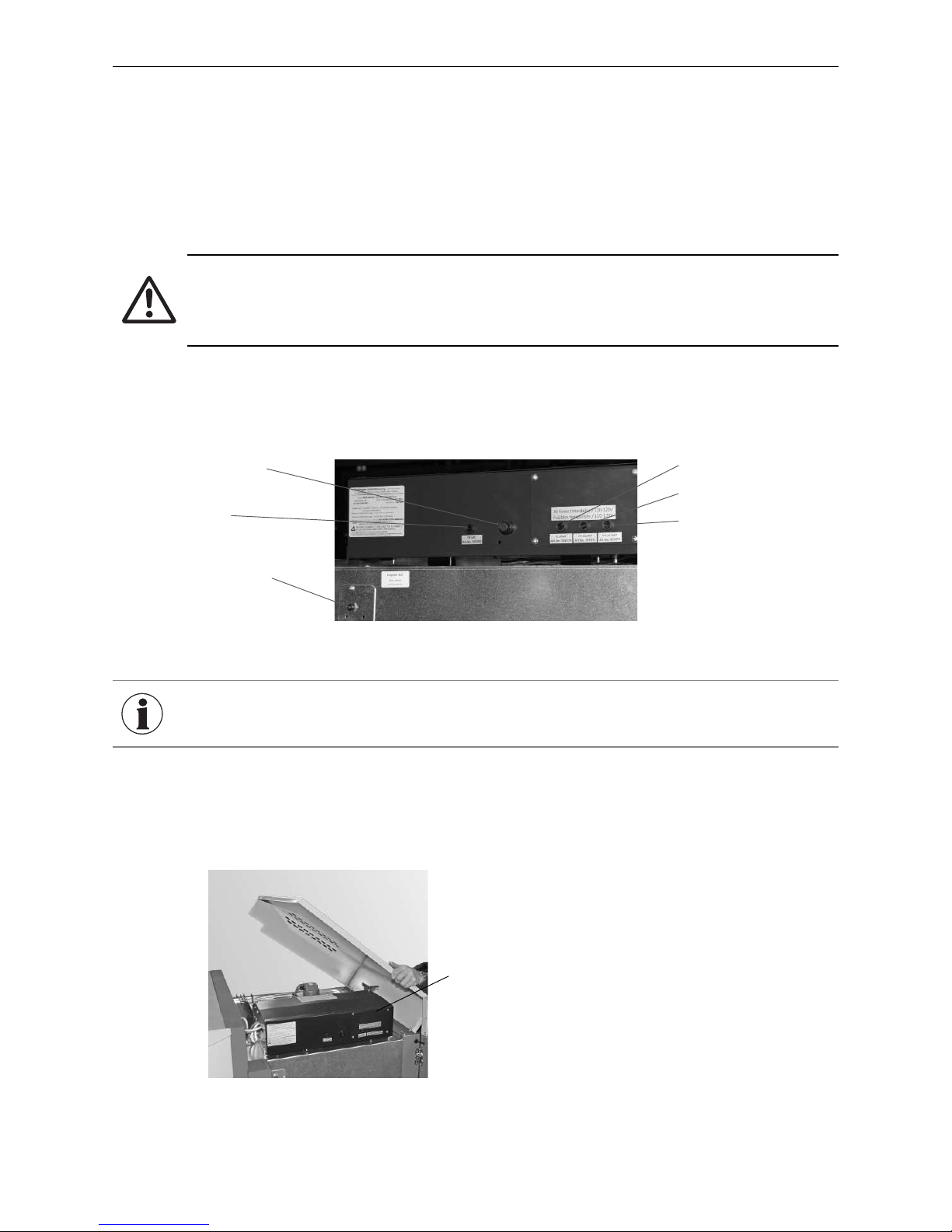
48
3. For the Electrician
3. For the Electrician
3.1 Electrical connections
The boiler/heater and related accessories are designed to be installed in dry areas only (protection type IP 10).
Installation of electrical components may only be performed by a qualified technician. The regulations and
specifications of local ordinances must be followed.
The boiler is pre-wired and internally fused with a T 20 A fine-wire fuse to protect against short circuit. In areas
with increased power surge risk (e.g., lightning strikes in regions prone to storms), we recommend installation
of an appropriate surge protector.
Attention!
– The mains connection must be protected against short circuit with a 25 A delayed-action fuse.
– On site, the technician must install an all-pole disconnect with at least a 0.12in / 3 mm contact
gap at the main access point.
All electrical connections are located in the control panel under the right cladding cover – Fig. 110.
The control panel is set up on 2 levels (a top part and bottom part). The top part of the control panel contains the
BioWIN XL main board, while the bottom part of the control panel contains the connection terminals.
INFORMATION
Electrical cables must not touch heating and exhaust pipes, nor come into contact
with non-insulated boiler/heater components. They are to be sufficiently braced
and provided with a protective tube.
Fig. 108 Control panel
Cover of safety thermostat Device fuse F1-20 AT
Device fuse F4-12.5 AT
Device fuse F3-12.5 AT
Cover of safety thermostat
auger tube
Device fuse F2-5 AT
Fig. 109 Removing the cladding cover
control panel
Page 49
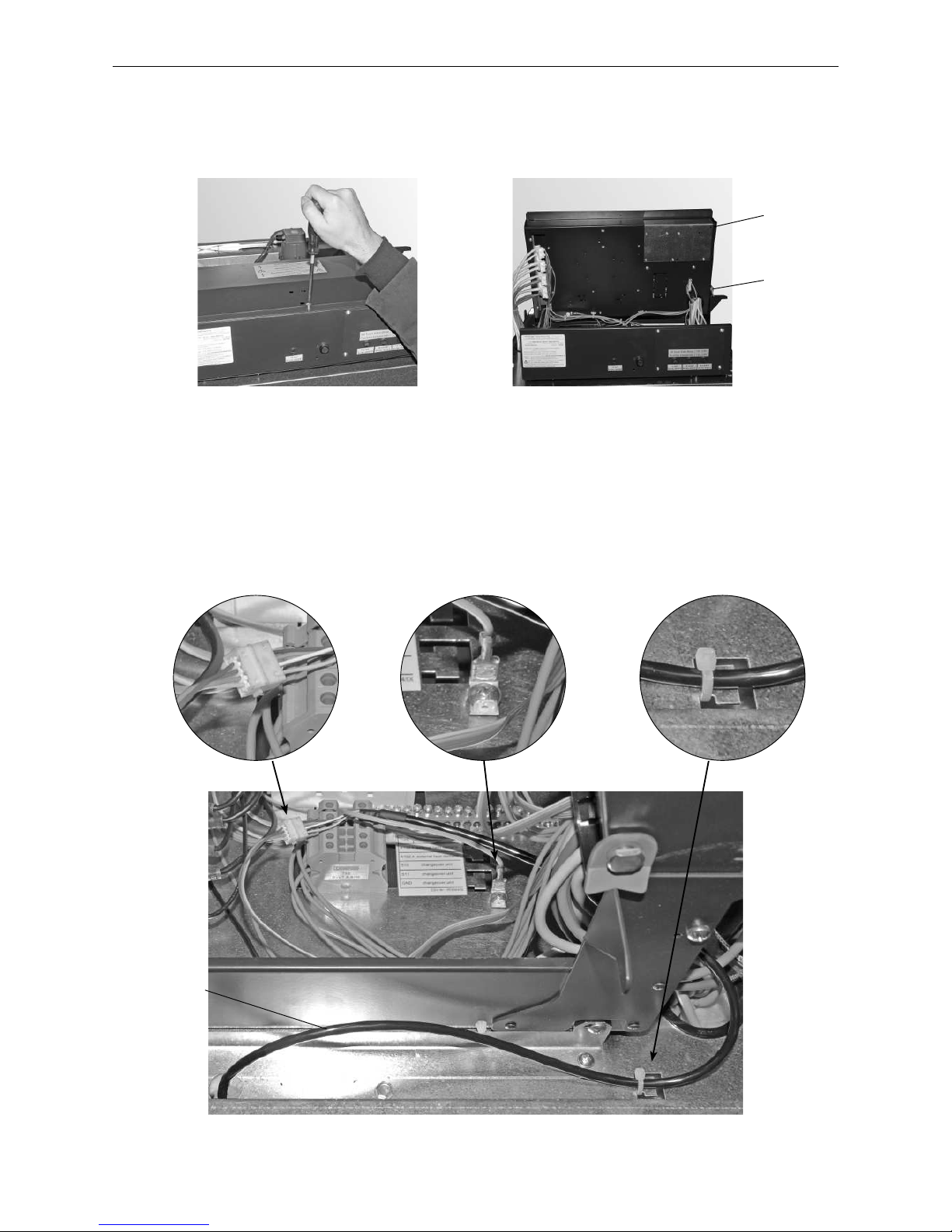
49
3. For the Electrician
3.1.2 Connecting the InfoWIN
PLUS
cable to the control panel
– Route InfoWIN
PLUS
cable into control panel at rear right, secure with cable ties, and connect plug and
grounding terminal – Fig. 112.
Fig. 112 Routing and connecting InfoWIN
PLUS
cable
Fig. 110 Loosening screw at front and
removing control panel cover
Fig. 111 Folding up top part of control panel
3.1.1 Opening and closing the control panel
– Loosen 1 screw on top of control panel cover and take off cover – Fig. 110.
– Fold up control panel top until it engages in lock at side – Fig. 111.
To close the top part of the control panel again, loosen the side lock and secure with screw at front.
Control panel
top part
Lock
InfoWIN
PLUS
cable
Page 50
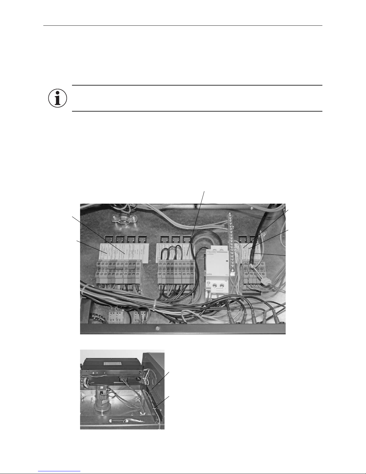
50
3. For the Electrician
3.1.3 Electrical connection for Power supply 110 V AC, external control,
changeover unit, suction turbine
3.1.3.1 Power supply 110 V AC
– We recommend using fine-wire PVC sheathed cables, e.g. 3 x AWG 15 nominal cross-section.
Cable duct
Low-voltage
(110–230 V AC)
Cable duct
Extra-low
voltage
(sensor)
Fig. 113
Fig. 114 Cable ducts - rear view
Power supply
110 V AC
Suction turbine
110 V AC
changeover unit
12 V DC
changeover unit 230 V AC
external control
3.1.3.2 Operation with external control, with buffer only
a) Heating requirement (setpoint specification) with 2-point controller
The 2-point controller switches the burner ON/OFF with a potential-free contact via the „external heating re-
quirement“ interface of the BioWIN XL.
b) Heating requirement (setpoint specification) with analogue interface
The controller passes the external boiler temperature setpoint via the analogue 0–10 V interface.
InfoWIN
PLUS
cable
Information!
Be sure to note the separate wiring of the extra-low voltage line (sensor) and low-voltage line
(110-120 V AC)! – Fig. 93.
Page 51
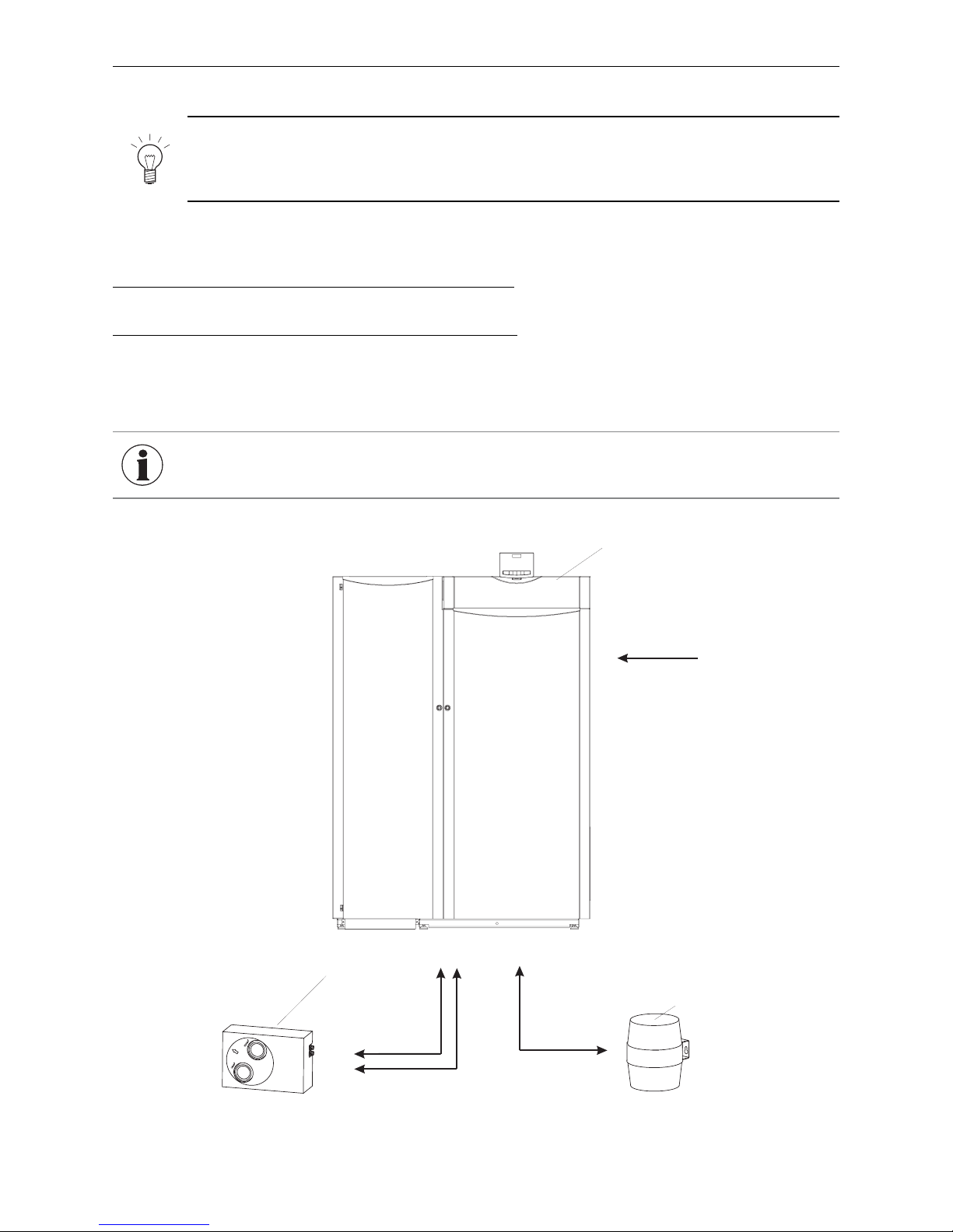
51
3. For the Electrician
110–230 V AC
2
1
3
3 x AWG 15
min. 3 x AWG 17
(no ground)
4 x AWG 15
3 x AWG 15
Fig. 115 Electrical connection between suction turbine and changeover unit
1 ..........BioWIN XL
2 ..........Suction turbine
3 ..........Changeover unit
3.1.3.3 Changeover unit, suction turbine
Note!
Each cable must be routed separately together with the delivery and return air hoses. The cables
can be routed together with the hoses through the fire protection collars to the suction turbine or
to the changeover unit.
The cables must not be too short or under tension in the cable ducts. For connection diagrams for the suction
turbine and changeover unit, see section 6. electrical connection diagrams.
Connection between BioWIN XL and suction turbine (Fig. 115):
We recommend a 110–230 V AC cable: 3 x AWG 15
Connection between BioWIN XL and changeover unit (Fig. 115):
Two separate cables are needed to connect the changeover unit.
– For the limit switches, a 12 V DC cable: min. 3 x AWG 17 (no ground). We recommend using a shielded cable if
the cable is longer than 16.4 ft / 5 m
– For the motor, a 110–230 V AC cable: 4 x AWG 15
INFORMATION The sensor and data cables (low voltage) should be routed in separate conduits.
Page 52
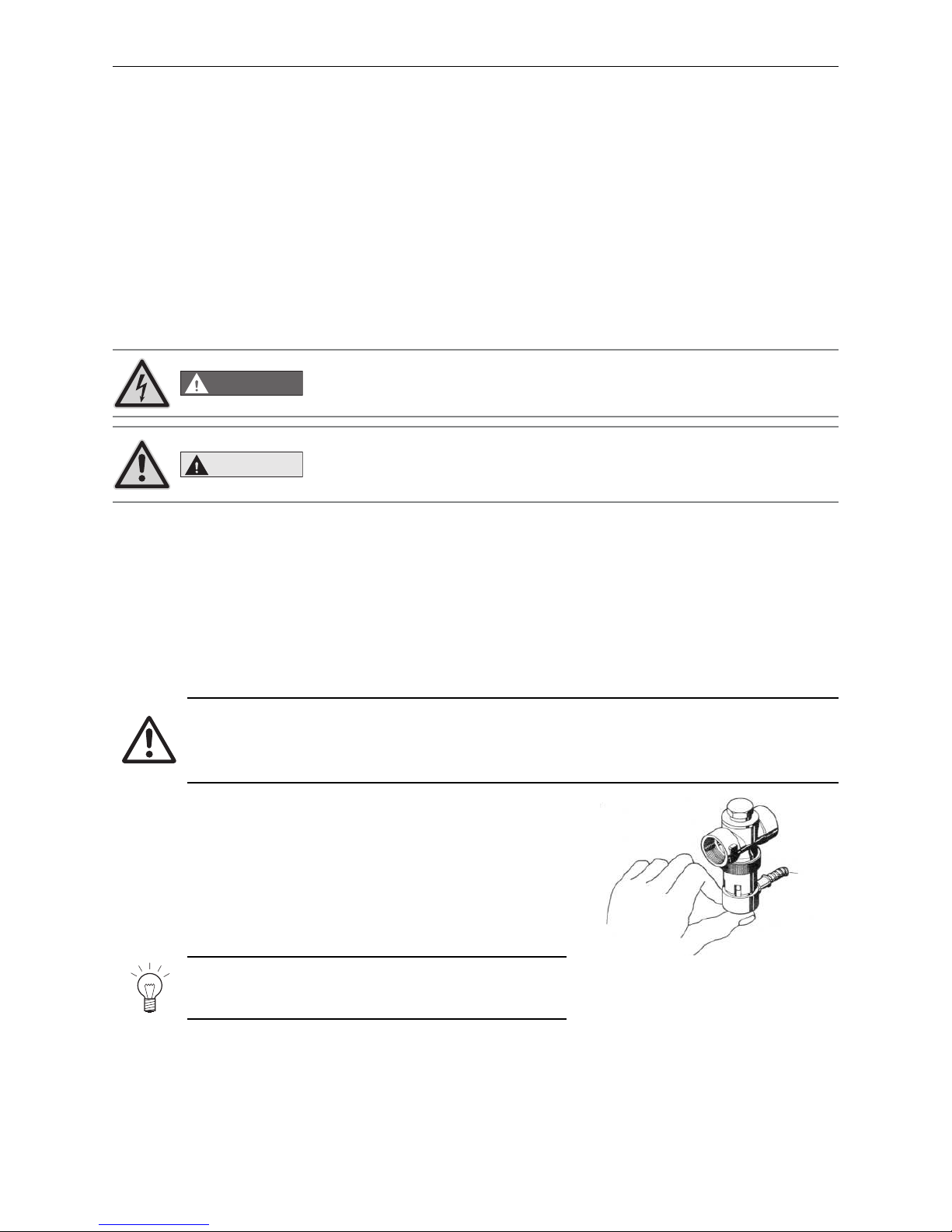
52
4. For the Service Technician
4. For the Service Technician
4.1 Start-up and operating instructions
The Windhager Customer Service or customer service partner will start the boiler/heater and familiarize the
customer with the system operations and cleaning procedures. Start-up and maintenance are part of the guarantee requirements of the “guarantee limitations” – see chapter 2.11.
We recommend that you obtain a maintenance service contract.
4.2 Service and repair work
Service and repair may be performed only by appropriately qualified technicians.
LabelidentGmbH Art.-N o.:W 08-05
DANGER
The ON/OFF Button does not turn OFF the power! The boiler/heater and
all accessories are still energized! To turn OFF the power (e.g., for repairs),
disconnect the main power via the circuit breaker.
CAUTION
After the emergency shut-off switch trips, the boiler/heater and accessories are
NOT completely without power!
When replacing system components (pumps, mixing valves, etc.), stop all power
input (e.g., disconnect main power via circuit breaker).
Please note:
Disconnect the main circuit breaker before opening the control panel for service or repair purposes. Remove the
cladding cover.
4.3 Checking and servicing the thermal discharge safeguard
(Please inform your customer)
Attention!
The function of the thermal discharge safeguard must be checked once a year by a technician and
the amount of limescale in the thermal safety device must be checked. If there is limescale in the
thermal safety device, it must always be removed.
– Press the red cap against the valve (Fig. 116) > Water must flow out
into the funnel.
– Little outflow at funnel > Limescale in thermal safety device (pump
limescale remover, e.g. formic acid, through the thermal safety device).
– Thermal discharge safeguard dripping > Clean the seal on the
piston and valve seat. If the seal is damaged > Replace the piston.
Note!
There is no need to remove the fitting for this purpose!
Fig. 116 Thermal discharge safeguard,
pressing red cap against valve
Page 53
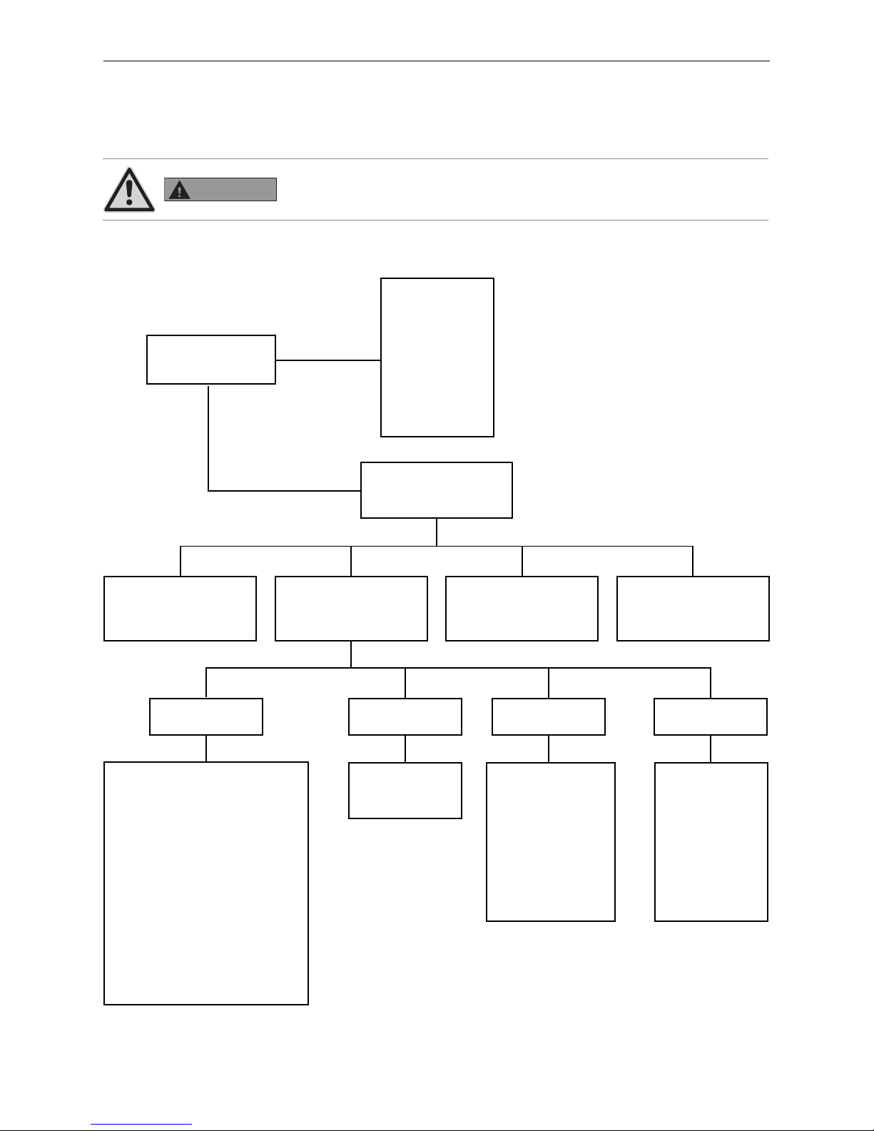
53
4. For the Service Technician
4.4 Service level
System parameters, start-up tests, or actuator tests can be displayed, modified and/or performed on the Service
level.
Structure on the Service level:
1 Only displayed when an MESplus control is present and this has been adjusted by a trained service technician in the basic settings.
WARNING
Only trained service personnel may perform system modifications on the Service
level.
Menu
Number of burner starts
Fuel quantity auger conveyor
Delivery time ignition phase
Hysteresis Burner ON
Maximum value of set temperature
Set temperature ext. heating requirement
Type of pellet feed system
Operating time of suction turbine
Profile ash removal
Correction of cleaning interval
Flue gas thermostat or Air intake flap
Limits for blower speed
Minimum operating time with buffer
Parameters
Operator level
Settings on the operator level
see BioWIN XL operating
manual.
Service level
Reserved for trained service
personnel only.
Information level
(see operating manual for
BioWIN XL)
MES Module
1
(see separate instructions for
InfoWIN
PLUS
Master operation)
InfoWIN
PLUS
basic
settings
(see section 4.5)
Actuator test
Induced draught fan
Auger conveyor
Ash removal
Ignition element
Ash conveyor
Heating surf. cleaning
Suction turbine
Probe switching
Boiler pump
Settings
Install display module
Boiler no
Language selection
Temperature format
Time format
Date format
Weight
Function
Start-up
Auger conveyor
Feed
Language selection
Boiler
MB
SMS
ELG
Ethernet
Update Software
Update Firmware
Display contrast
Page 54
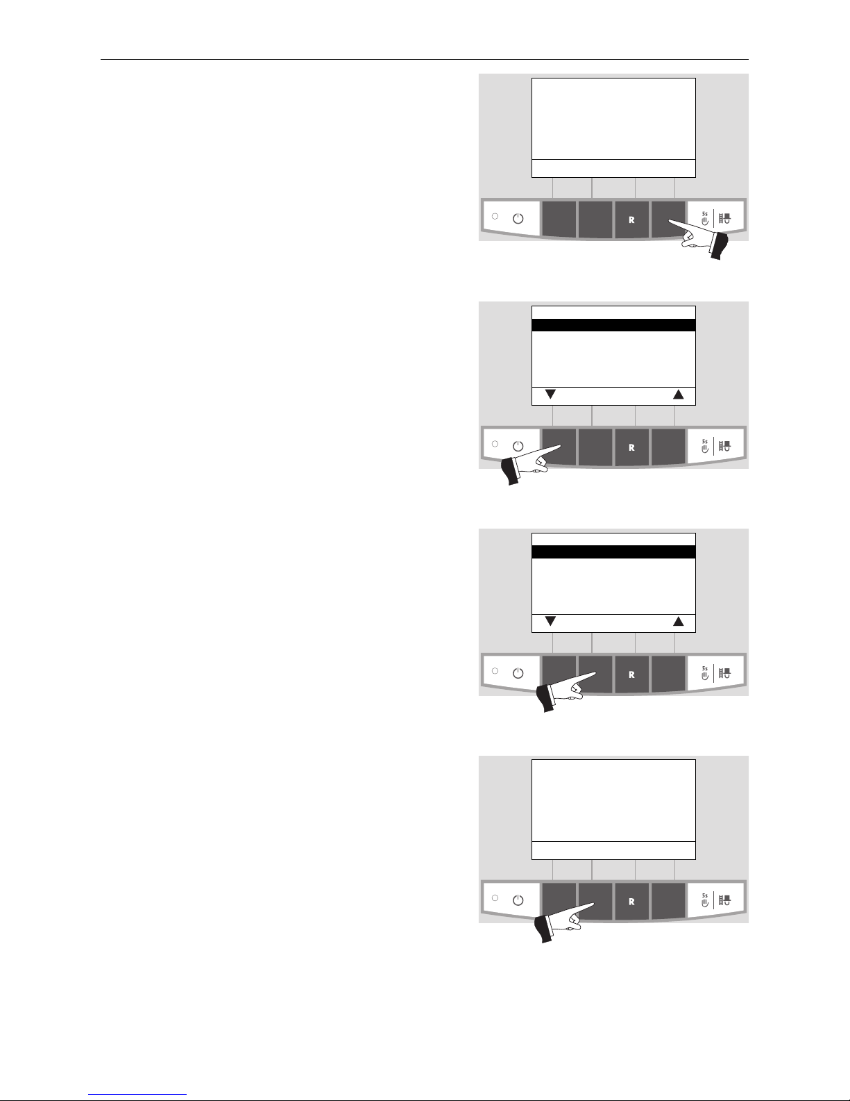
54
4. For the Service Technician
Fig. 117
Boiler temperature
(Operating phases)
Info Menu
107
°F
Service level
Press the Menu button (Fig. 117) to show the “Operator level”, “Service level”, “Information level”, and “MES Module”1
on the display – Fig. 118.
Fig. 118
Operator level
Service level
Information level
MES Module
1
choose back
Fig. 119
Operator level
Service level
Information level
MES Module
1
choose back
Fig. 120
Service level only
for trained service personnel
5s
Use the arrow buttons to select “Service level” – Fig. 118.
Press and hold the choose button for 5 seconds (Fig. 119).
The display will show “Service level only for trained service
personnel” – Fig. 120.
Press for 5
seconds
Press for 5
seconds
1 Only displayed when an MESplus control is present and this has been adjusted by a trained service technician in the basic settings.
Page 55
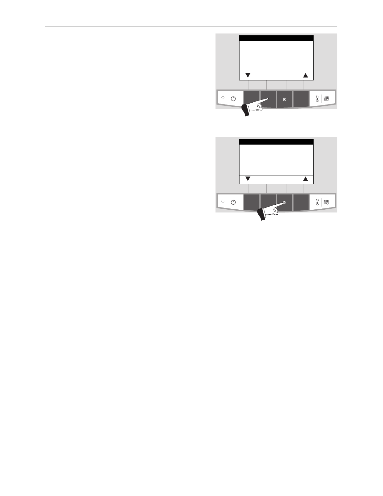
55
4. For the Service Technician
Select the required item: “Parameters”, “Start-up”, “Actuator test” or “Settings.“ Use the choose button to confirm the
choice – Fig. 121.
For further settings, see chapters 4.4.1 – 4.4.4.
Fig. 121
Parameters
Start-up
Actuator test
Settings
choose back
Fig. 122
Parameters
Start-up
Actuator test
Settings
choose back
Exit the menu or sub-menu by pressing the back button
(Fig. 122) or by waiting 10 minutes.
Page 56
56
4. For the Service Technician
BioWIN XL BWE 350 NA / BWE 450 NA / BWE 600 NA
Actual value
Factory setting:
Setting range:
61.7 lbs/hr / 28 kg/h
±11 lbs / 5 kg of range
Range
Factory setting:
Setting range:
61.7 lbs/hr / 28 kg/h
48.5-79.4 lbs/hr (22–36 kg/h)
Correction
Factory setting:
Setting range:
0
± 11 lbs / 5 kg
Delivery time ignition phase
Fuel quantity in the ignition phase.
BioWIN XL BWE 350 NA BWE 450 NA BWE 600 NA
Factory setting: 240 s 280 s 210 s
Setting range: 190 – 290 s 230 – 330 s 160 – 260 s
Hysteresis Burner ON
Switching hysteresis for burner control.
Factory setting: 5 K
Setting range: 0 – 20 K
4.4.1 Parameters
Use the arrow buttons to select the following parameters. Use the choose button to confirm the choice.
– Number of burner starts
– Fuel quantity auger conveyor
– Delivery time ignition phase
– Hysteresis Burner ON
– Maximum value of set temperature
– Set temperature ext. heating requirement
– Type of pellet feed system
– Operating time of suction turbine
– Profile ash removal
– Correction of cleaning interval
– Flue gas thermostat or air intake/exhaust flap
– Limits for blower speed
– Minimum operating time with buffer
Number of burner starts
The BioWIN XL‘s number of burner starts is displayed.
Fig. 123
Number of burner starts
1.350
back
Fig. 124
Fuel quantity
Auger conveyor
Actual value 55 lbs
Range 61.7 lbs
Correction 0
choose back
Fuel quantity auger conveyor
The calculated fuel quantity (actual value) and the range are displayed in lbs/h
or kg/h, and can be adjusted.
Fig. 125
Delivery time ignition phase
Actual value 240 s
min. 190 s
max. 290 s
– save back +
Fig. 126
Hysteresis Burner ON
Actual value 5 K
min. 0 K
max. 20 K
– save back +
Page 57
57
4. For the Service Technician
Fig. 127
Maximum value of set
temperature
Actual value
167°F
min. 140 °F
max. 185 °F
– save back +
Maximum value of set temperature
This is the maximum setpoint achievable in normal heating operation.
Factory setting: 167 °F / 75 °C
Setting range: 140 – 185 °F / 60 – 85 °C
Fig. 128
Set temperature ext.
heating requirement
Actual value 158°F
min. 95 °F
max. 185 °F
– save back +
Set temperature ext. heating requirement
This is the set temperature for external heating requirement.
Factory setting: 158 °F / 70 °C
Setting range: 95 – 185 °F / 35 – 85 °C
This setting is not available in North America.
Type of pellet feed system
Setting for if the operation is without a feed system, with 2 to 8 probes, or with
a mixer (buried tank).
Factory setting: Without feed system
The following settings are available:
USA/Canada
For changeover unit with 3 probes: Suction turbine with 2 probes
Suction turbine with 3 probes
Europe only:
For changeover unit with 8 probes: Suction turbine with 4 probes
Suction turbine with 6 probes
Suction turbine with 8 probes
For buried tank with mixer Suction turbine with mixer
Fig. 129
Type of pellet feed system
without feed system
Suction turbine with 2 probe
Suction turbine with 3 probe
Suction turbine with 4 probe
Suction turbine with 6 probe
choose back
Fig. 130
Type of pellet feed system
Suction turbine with 8 probe
Suction turbine with mixer
choose back
Operating time of suction turbine
Factory setting: 120 sec.
Setting range: 90 – 240 sec.
Fig. 131
Operating time of
suction turbine
Actual value 120 sec.
min. 90 sec.
max. 240 sec.
– save back +
Profile ash removal
This setting can be used to adjust the removal of ash from the burner pot for
different levels of pellet quality.
Factory setting: Stage 1
Stage 0 to Stage 3
very low proportion of ash very high proportion of ash
(possibly formation of slag)
INFORMATION
Restore factory settings for each delivery of
pellets.
Fig. 132
Profile ash removal
Stage 0
Stage 1
Stage 2
Stage 3
save back
Page 58
58
4. For the Service Technician
BioWIN XL BWE 350 NA BWE 450 NA BWE 600 NA
Minimum Maximum Minimum Maximum Minimum Maximum
Factory setting: rpm 750 2100 1100 2600 1050 2700
Setting range: rpm 750–950 2000–2400 1000–1300 2600–2700 950–1250 2600–2700
Minimum operating time with buffer
This function is not yet available.
Correction of cleaning interval
The cleaning interval is dependent both on the ash removal profile, and on the
proportion of ash in the pellets. This setting can be used to extend or shorten
the cleaning interval by ±50 %.
The standard setting is a cleaning interval determined by testing.
Factory setting: 0 %
Setting range: ±50 %
Fig. 133
Correction of Cleaning interval
Actual value
0 %
min. -50 %
max. +50 %
– save back +
Flue gas thermostat or air intake/exhaust flap
This setting can be used to change the flue gas thermostat function (factory
setting) to the air intake/exhaust flap function.
Factory setting: Flue gas thermostat
With air intake/exhaust flap setting (Fig. 135):
Factory setting: Operating time 300 sec.
Setting range: 30 – 600 sec.
Fig. 134
Flue gas thermostat or Air intake
flap
Flue gas thermostat
Air intake/exh. flap
choose back
Fig. 135
Air intake/exh. flap
Operating time 300 sec.
min. 30 sec.
max. 600 sec.
– save back +
Limits for blower speed
Fig. 136
Limits for blower speed
Minimum 1100 rpm
Maximum 2600 rpm
choose back
Fig. 137
Minimum operating time
with buffer
Actual value 60 min.
min 0 min.
max 180 min.
– save back +
CAUTION
If too long of a cleaning interval is selected, the
ash container may overfill.
INFORMATION
The set operating time should be twice as long
as the actual operating time of the air intake/
exhaust flap.
Page 59
59
4. For the Service Technician
4.4.2 Start-up
The auger conveyor and the feed can be selected on the Start-up level with the arrow buttons, and confirmed
using the choose button. A self-test is started at the end of the start-up.
Fig. 138
Start-up
Auger conveyor
Feed
choose back
Auger conveyor
The auger conveyor can be turned on for 6 minutes.
Feed
Depending on the feed system settings, the feed and probes (including purging)
can be started.
4.4.3 Actuator test
The following actuators can be selected with the arrow buttons, then confirmed and started using the choose
button. The actuators are turned off again after 1 minute. A self-test is started at the end of the actuator test.
Fig. 139
Induced draught fan
Auger conveyor
Ash removal
Ignition element
Ash conveyor
Heating surf. cleaning
choose back
– Induced draught fan
– Auger conveyor
– Ash removal
– Ignition element
– Ash conveyor
– Heating surf. cleaning
– Suction turbine
– Probe switching
– Boiler pump
Fig. 140
Suction turbine
Probe switching
Boiler pump
choose back
4.4.4 Settings
This sub-menu contains the following settings:
– Install display module
– Boiler no.
– Language selection
– Temperature format
– Time format
– Date format
– Weight
– Function
Fig. 141
Install display module
Boiler no.
Language selection
Temperature format
Time format
Date format
choose back
Fig. 142
Weight
Function
choose back
Install display module
The install display module is not needed for an individual boiler; it only needs to
be used for a cascade system.
Fig. 143
Start installation procedure
Please press LON button on automatic firing device briefly
back
Page 60
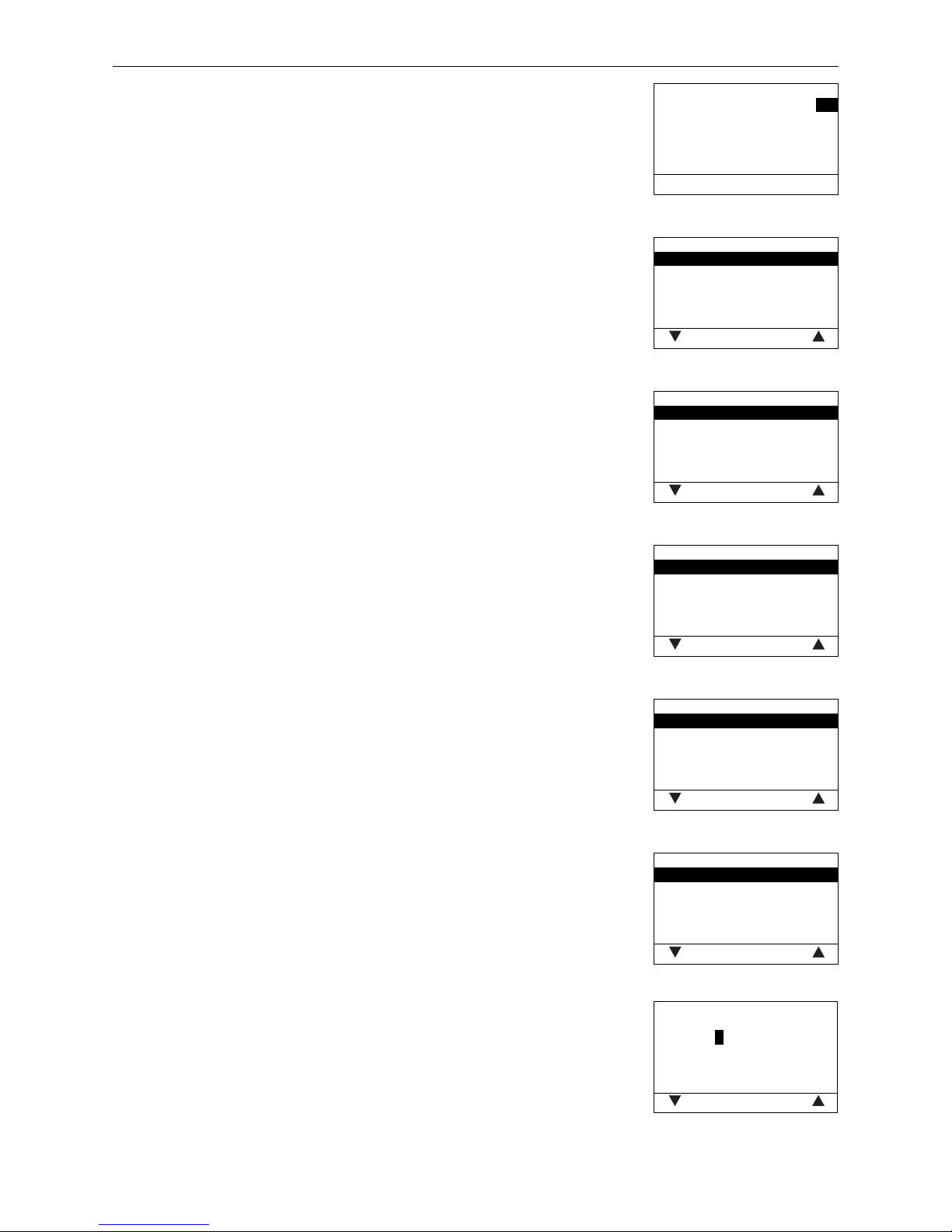
60
4. For the Service Technician
Fig. 144
Boiler no 0
– save back +
Boiler no
If a individual boiler is not required, a number must be assigned to each heat
generator (boiler) in a cascade system (only when MESplus KAS+ module is
used).
Factory setting: 0
Selection: 0 to 4
Fig. 145
Language selection
Deutsch
English
Française
Italiano
Dansk
save back
Language selection
The InfoWIN
PLUS
can show the display texts in various languages. The language
required can be selected in this sub-menu.
Fig. 146
Temperature format
°C
°F
save back
Temperature format
All temperatures are displayed in the chosen format (e.g., 87.0 °F or 30.6 °C).
Factory setting: °C
Selection: °C and °F
Fig. 147
Time format
24h
12h
save back
Time format
The time is displayed in the chosen format (e.g., 14:12 or 02:12 PM).
Factory setting: 24 h
Selection: 24 h or 12 h
Fig. 148
Date format
DD.MM.YYYY
MM/DD/YYYY
save back
Date format
The date is displayed in the chosen format (e.g., Wed 17.02.2010 or Wed
02/17/2010).
Factory setting: DD.MM.YYYY
Selection: DD.MM.YYYY
MM/DD/YYYY
Fig. 149
Weight
t, kg
tn. sh., lbs
save back
Weight
The weight is displayed in the chosen format (e.g., 6.5 kg or 14.3 lbs).
Factory setting: t, kg
Selection: t, kg or tn. sh., lbs
Function
The name (e.g., BioWIN XL) of the boiler can be changed with this setting.
Fig. 150
Function
BioWIN XL
choose back
<
Page 61
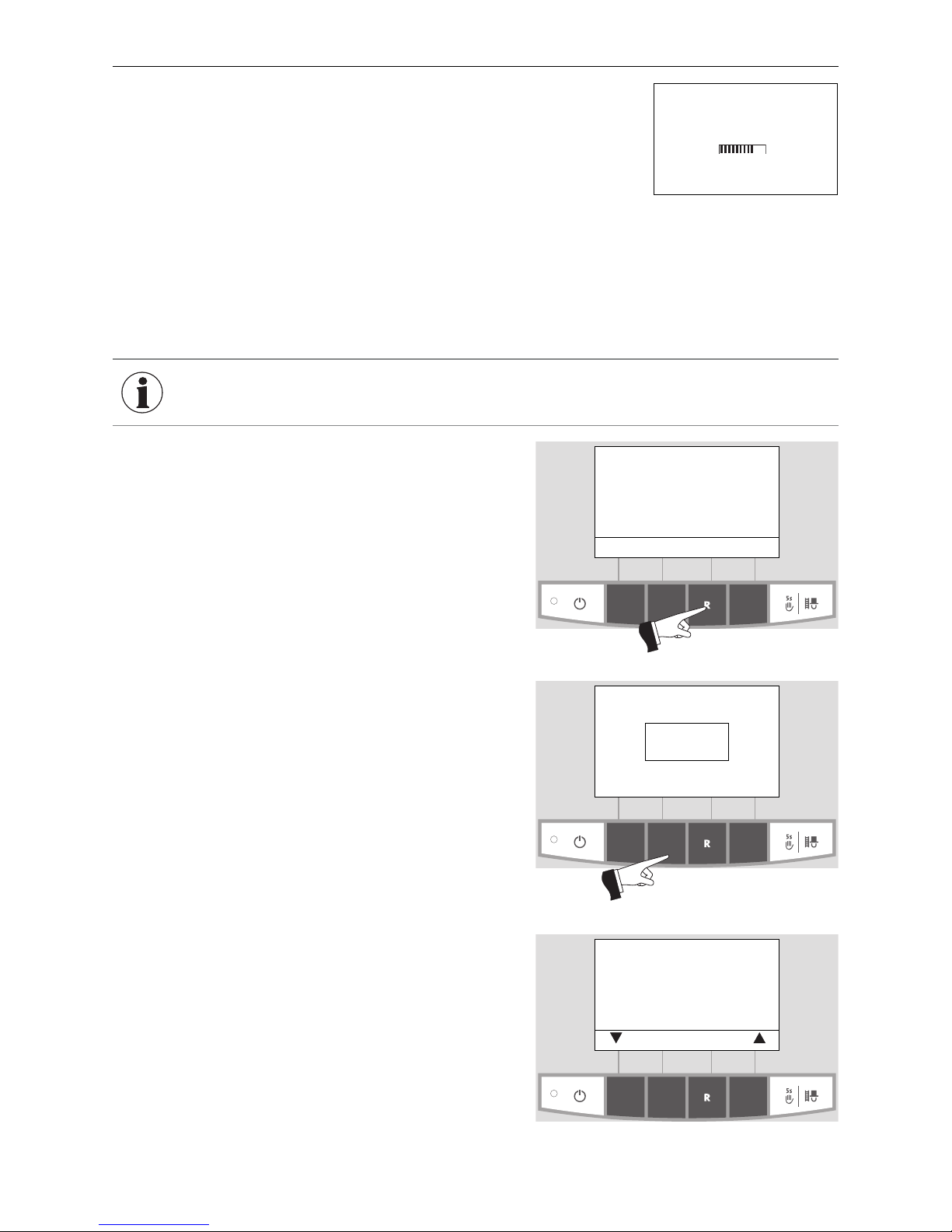
61
4. For the Service Technician
4.4.5 Installation of MES
PLUS
modules
Display if an MESplus module is installed (connected) or uninstalled
(disconnected).
Fig. 151
Installation procedure active
(Animated symbol)
4.5 InfoWIN
PLUS
basic settings
The display switches to the basic settings when “Version
....” (Fig. 153) is displayed and the button (shown inFig. 153)
is pressed for 5 seconds.
”Version ....“ is displayed,
– if the ”R“ button is pressed for 5 seconds on a standard
display – Fig. 152;
– if the InfoWIN
PLUS
was powered down and turned back
on.
The following settings are available in the basic settings:
– Language selection
– Boiler
– MB
– SMS
– ELG
– Ethernet
– Update Software
– Update Firmware
– Display contrast
Fig. 152
Boiler temperature
(Operating phases)
Info Menu
107
°F
Fig. 153
Version V4.00
30.4.2014
Press for
5 seconds
The basic settings are used to:
– set whether the InfoWIN
PLUS
controls a wood or pellet boiler/heater, or if it is solely used for master operation;
– turn the master operation functions on and off;
– activate/deactivate remote switching by text message.
The basic settings are set in the factory as per the order, before delivery.
Fig. 154
Language selection English
Boiler No
MB No
SMS No
ELG No
Ethernet
choose back
INFORMATION Only trained service personnel may perform modifications in the basic settings.
Page 62
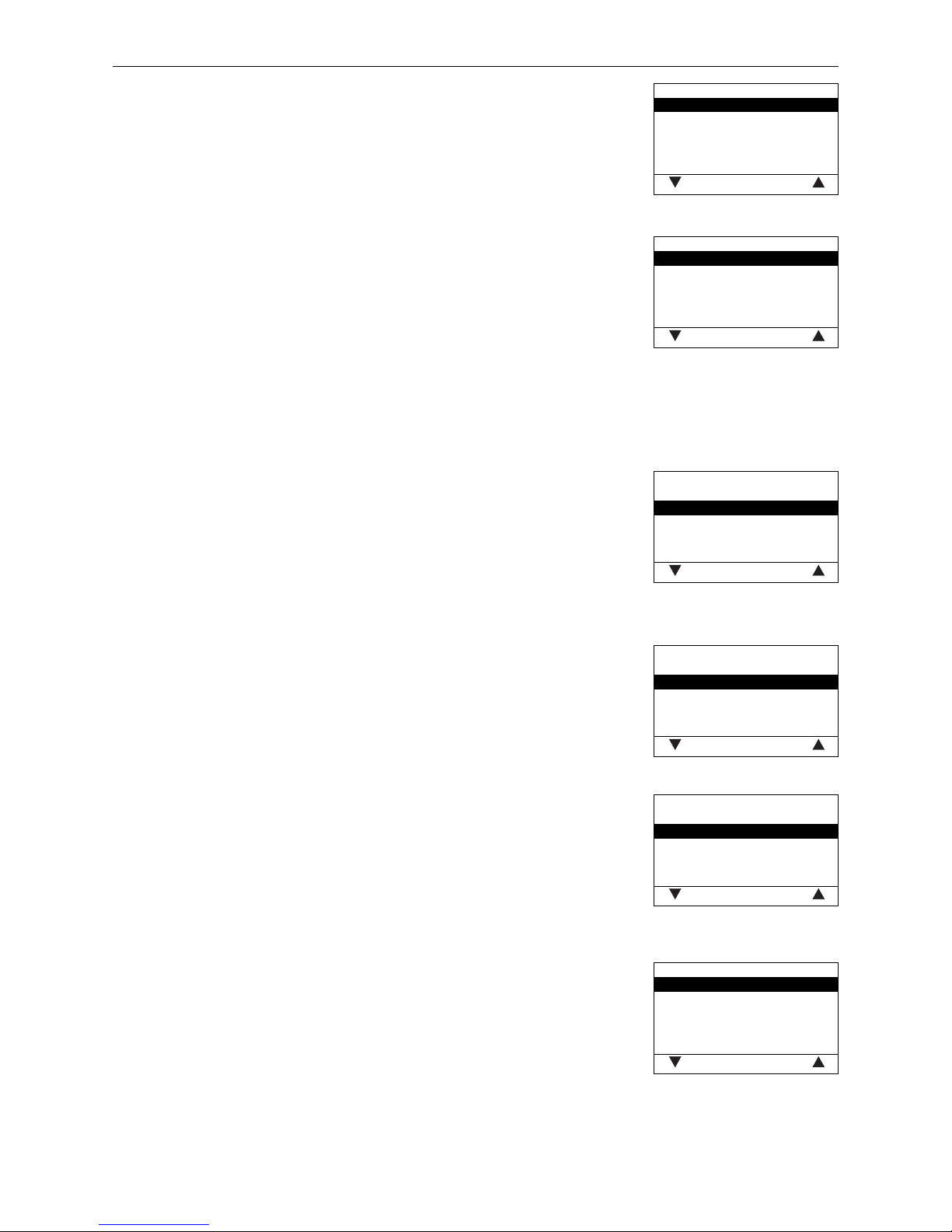
62
4. For the Service Technician
Fig. 155
Language selection
Deutsch
English
Française
Italiano
Dansk
save back
Language selection
The InfoWIN
PLUS
can show the display texts in various languages. The language
required can be selected in this sub-menu.
Fig. 156
Boiler
Pellets
Wood
Heating oil
Combi boiler
No
save back
Boiler
Setting to determine what kind of boiler/heater the InfoWIN
PLUS
controls, e.g.
wood or pellet boiler or whether it is solely used as master operation.
Factory setting: is set in the factory before delivery as per the order.
Selection: Pellets: BioWIN 2, BioWIN XL, FireWIN, VarioWIN usw.
Wood: LogWIN, SilvaWIN usw.
Heating oil: JetWIN, EcoWIN
Combi boiler: DuoWIN
No: No boiler/heater (e.g., for MultiWIN, only
master operation for remote switching)
Fig. 157
MB
Yes
No
save back
MB (Master operation)
Setting to define whether MESplus system control is present.
Factory setting: is set in the factory before delivery as per the order.
Selection: Yes: with MESplus system control
No: no MESplus system control
Fig. 158
SMS
Yes
No
save back
SMS
Setting to define whether remote switching by text message is possible.
Factory setting: is set in the factory before delivery as per the order.
Selection: Yes: with remote switching
No: no remote switching
Fig. 159
ELG
Yes
No
save back
ELG
These functions are not yet available.
Fig. 160
Ethernet
IP-Adresse 192.168.1.2
Subnet 255.255.255.0
Gateway 255.255.255.255
choose back
Ethernet
Setting the IP address, subnet mask and gateway address of the Ethernet interface for the InfoWIN
PLUS
.
Factory setting: IP-Adresse 192.168.1.2
Subnet 255.255.255.0
Gateway 255.255.255.255
Page 63

63
4. For the Service Technician
Fig. 161
Update Software
MAC-Adresse
0C-E5-D3-00-00-05
V4.00.00.001
start back
Update Software
The update procedure to update the InfoWIN
PLUS
software via the Ethernet in-
terface is being started.
Fig. 162
Update Firmware
start back
Update Firmware
The update procedure to update the LON Controller firmware is being started.
The LON Controller firmware is included in the InfoWIN
PLUS
software, therefore
no external update tool is required.
Fig. 163
Display contrast
Correction 5
– back +
Display contrast
Adjusters to set the contrast of the display.
Factory setting: 5
Setting range: 0 – 10
Page 64
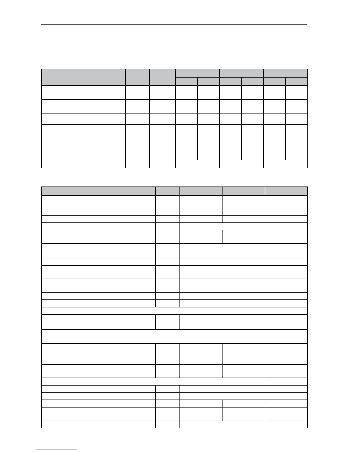
64
5. Technical Data
5.2 Technical data – General
5. Technical Data
5.1 Technical data for calculating the flue gas system acc.
to EN 13384-1
BioWIN XL pellet boiler Unit BWE 350 NA BWE 450 NA BWE 600 NA
Boiler class according to EN 303-5 3 3 3
Nominal thermal output range
kBTU
(kW)
34.1–119.4
(10–35)
46.1–153.5
(13,5–45)
61.4–204.7
(18–60)
Radiation losses Rated load kBTU (kW) 1.8 (0.53) 2.05 (0.6) 2.3 (0.66)
Boiler water volume l 120
Water-side resistance ∆T = 20 K
∆T = 10 K
psi (mbar)
0.098625662 (6.8)
0.358243212 (24.7)
0.156640757 (10.8)
0.572899064 (39.5)
0.268319815 (18.5)
0.97900473 (67.5)
Boiler temperature control range °F (°C) 140–185 (60–85)
Max. operating pressure psi (bar) 43.5 (3)
Test pressure psi (bar) 65.25 (4.5)
Integral fuel hopper
l
lb (kg)
208
297.7 (135)
Net weight of fully assembled boiler
Transport weight of boiler part
lb (kg)
1543.5 (700)
1058.4 (480)
Dimensions W x D x H
in (mm) 48 x 39.1 x 70.9 (1220 x 1000 x 1800)
Installation dimensions
in (mm) 30.7 x 38.6 x 70.9 (780 x 980 x 1800)
Electrical power consumption of pellet feed:
Automatic pellet feed W 1785
Maximum current consumption, pellet feed
A 15.8
Values from type test
Testing office TÜV SÜD Munich, test report no.: H-C4 1190 - 00/11 and H-C5 1190 - 00/11
Firing efficiency Rated load
(100-qA) Part load
%
93.1
94.7
91.8
92.8
92.5
94.0
Boiler efficiency Rated loadη
W
% 91.2 90.0 90.1
Flue gas temperature Rated load
Part load
°F (°C)
285.8 (141)
192.2 (89)
327.2 (164)
210.2 (99
312.8 (156)
206.6 (97)
Electrical power consumption of pellet boiler:
Maximum current consumption A 18.2
Maximum for igniting W 2186
Ignition process Wh 409 409 409
Heating mode Rated load
Part load
W
103
43
122
53
156
63
Idle operation W 7
BioWIN XL pellet boiler
Formula
symbols
Unit
BWE 350 NA BWE 450 NA BWE 600 NA
min. max. min. max. min. max.
Nominal thermal output
Q
N
kBTU
(kW)
34.1
(10.0)
119.4
(35.0)
46.1
(13.5)
153.5
(45.0)
61.4
(18.0)
204.7
(60.0)
Nominal heat load
(firing thermal output)
Q
B
kBTU
(kW)
38.6
(11.3)
130.7
(38.3)
51.2
(15.0)
168.9
(49.5)
68.2
(20.0)
225.2
(66.0)
Volume concentration of CO
2
σ (CO
2
) % 9.1 13.3 9.2 13.5 9.3 13.8
Flue gas mass flow rate - rated load
.
m
lb/s
(kg/s)
0.02
(0.0089)
0.047
(0.0215)
0.026
(0.0118(
0.06
(0.0274)
0.034
(0.0155)
0.079
(0.0358)
Flue gas temperature - rated load
(Average between two cleaning intervals)
TW
°F
(°C)
179.6
(82)
284.0
(140)
186.8
(86)
294.8
(146)
194.0
(90)
309.2
(154)
Necessary feed pressure PW Pa 5 10 5 10 5 10
Flue gas connection diameter in (mm) 5.91 (150) 5.91 (150) 5.91 (150)
Page 65
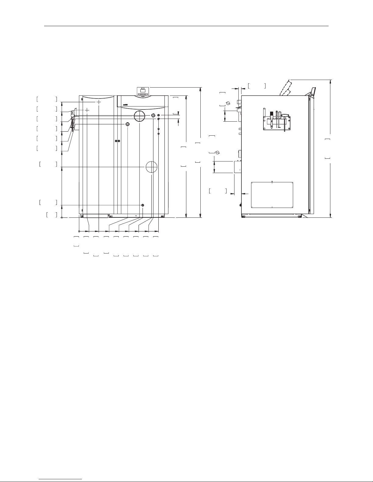
65
5. Technical Data
5.3 Dimensional sketches
50mm
1,97in
1673mm
65,88in
1784mm
70,23in
0mm
0in
170mm
6,69in
693mm
27,3in
1280mm
50,39in
1390mm
54,72in
1353mm
53,27in
1400mm
55,12in
1473mm
57,99in
1583mm
62,32in
0mm
0in
109mm
4,28in
269mm
10,58in
663mm
26,1in
870mm
34,25in
826mm
32,52in
991mm
39,01in
1015mm
39,95in
1087mm
42,79in
KV
KR
ZL
A
B
E
TV
KT
SB
Fig. 164 BioWIN XL pellet boiler
KV ........Boiler feed (5/4“ pipe)
KR ........Boiler return (5/4“ pipe)
TV ........Thermal valve sensor (1/2“ sleeve)
SB ........ Safety device (1/2“ pipe)
E ..........Discharge
A ..........Pellet feed (Ø 1.97 in / Ø 50 mm pipe)
B .......... Reverse air flow (Ø 1.97 in / Ø 50 mm pipe)
KT ........Boiler temperature sensor
ZL ........Supply air for operation independent of room air
All dimensions in inches / mm:
Front view Side view
37mm
1,46in
1889mm
74,38in
96mm
3,78in
5,91in
150
6,28in
160mm
Page 66
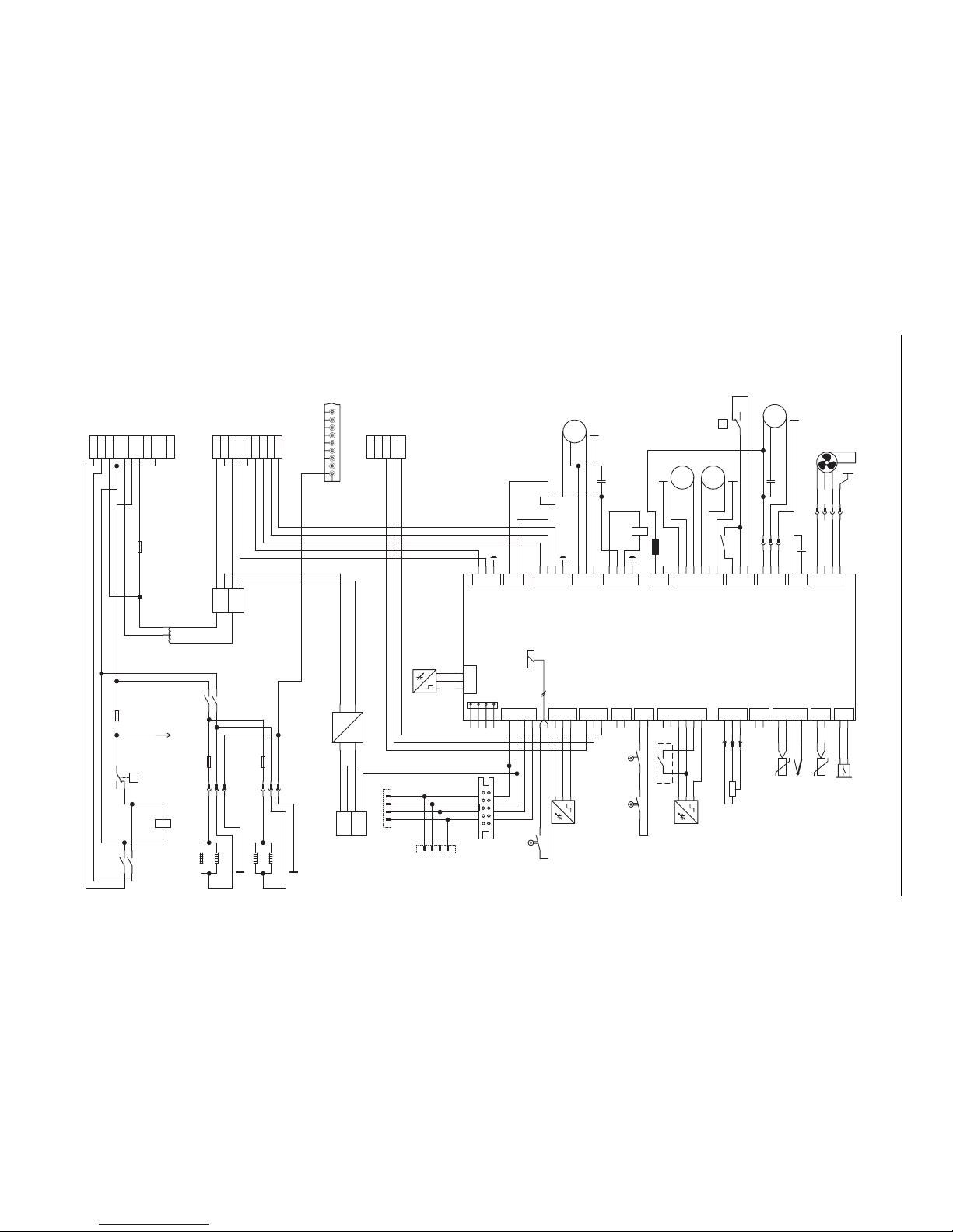
66
6. Electric Connecting Diagrams
E
D
C
B
A
12 GND
-XD
PE
L2L1N
PE
induced draught
motor fan
-M0c
1 1
2 2
3 3
-XG
4 4
-C1
capacitor
2 1
-C2
capacitor
2 1
ignition element
2 1
bl
a
c
k
brown
blue
-XG
hall sensor
br
ow
n
blue
black
-S4
Proximity Switch
flap
brown
blue
black
-S4
Proximity Switch
Vorratsbehälter
limit switch additional further air flap
24 23
Lon-
Lon+
GND
-X2
12V
-XB
4 3
2 1
-K1
-XG
PE
-XA
Lon ST
Lon-
Lon+
GND
-X2
12V
N
GND
12V
L
230V
12V DC
-T2.1
transformer
230V / 12V DC
11
12
14
-B7.1
safety temperature
limiter
conveyor screw 100°C
11
12
14
-B8.1
safety temperature
limiter
boiler 100°C
M
PE
L2NPE
L1
motor for conveyor
screw
-M2.1
3 1
door safety switch
M
PE
L
N
PE
motor heating
surface cleaning
-M4.1
M
PE
LNPE
motor ash
removal
-M1.1
white
green
combustion chamber sensor
-V9.1
flue gas sensor
-V14.1
* boiler sensor
-V4.1
PE
-L1
M
PE
L2NPE
L1
motor for ash removal
-M12.1
-C3
capacitor
2 1
Pressure Sensor
-P2.1
2 1
2 1
2 1
14 11
-K2
1 2
brown
blue
black
rotation monitor
sensor
-P7.1
3 1
optionales/zubehör
X1
X17
X22 X21 X16 X15 X14 X13 X18
X12 X11
X10
X23
X0
X2
X19
X20
X5
X6
X24
X7
X3 X4
X8
X9
221
143212132
1
65432
1212132
1
3
2
1
Lon-
Lon+
GND
+12V
3
2
1
GND
Lo
n
+
Lon-
+12
V
123
1
2
1
2
3
4
123
1
2
3
4
1
2
1
2
3
4
5
6
1
2
3
1
2
3
1
2
1
2
3
4
FA-BioWIN XL
L
N
PE
L
N
LL
N
PE
RL
L
L
L
N
PE
L
N
PE
NPEN
LL
RL
N
PE
L
L'
L'
RL
N
PE
L
L
N
PE
LON
GND
12V
GND
GND
GND
GND
G
N
D
G
N
D
hall.signal
hall.5V+
hall.GND
GND
GND
GND
GND
GND
EDV Nr.:
2
1
3
monitoring
connection power
supply 230 VAC
suction turbine
probe switching
limit switch ash
compression
shaker
ignition element
blocking unit
conveyor screw
counter clockwise
rotation
motor ash
compression heating
surface
STB screw
STB boiler
conveyor screw
clockwise rotation
capacitor ID-fan
suction draught ID-fan
container full
limit switch zero point S10
limit switch position S11
external heat
demand
combustion chamber
door switch
limit switch shaker
t
ank
empt
y
l
i
mit
swi
t
ch
sup.
c.
analog 0-10V
boiler sensor
combustion chamber
sensor
flue gas temp. sensor
pressure switch
500VA
110V
230V
transformer
1L
1N
2N
2L
A2 A1
-K3
120V
1 2
-K3
1N2N3L
4L
-XE
1 N'
2 L'
3 L'
4 N
5 N
6 L
7 L
18 LL
17 lwco
16 lwco
15 N'
14 N
13 L'
19 RL
20 N
23 S10
2
4 S1
1
25 GND
21
F2
fuse 5A/T
A2 A1
-K1
230V
A2 A1
-K2
230V
21
F
1
fuse 20A/T
PE
21 EH
22 EH
8 CP
12 L
24
21
21
F3
fuse 12,5A/T
21
F
4
fuse 12
,
5A/
T
PE
PE
PE
9 N
10 N
11
L extra pcb
094893/00
6. Electric Connecting Diagrams
6.1 Basic BioWIN XL circuitry
Page 67
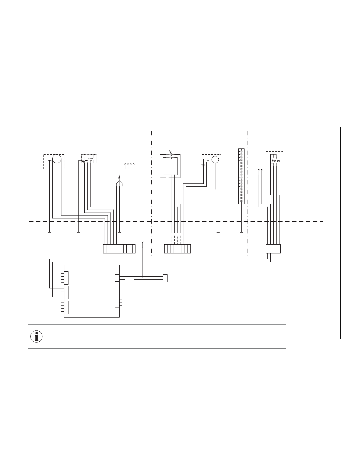
67
6. Electric Connecting Diagrams
2 L'
3 L'
4 N
5 N
6 L
7 L
13 L'
14 N
15 N'
16 lwco
17 lwco
19 RL20 N
23 S1024 S11
25 GND
P
1
2
4
110V - 120V
LWCO
L
N
PE
LPEN
supply voltage 110-120V/60Hz
internal
external
*wire bridge
connecting terminal
*wire bridge
*wire bridge
S11
GND
S10
changeover unit
M
PE
L
N
PE
suction turbine
110V - 120V
-M12.1
X100
X102
X1
0
4
X103
X101
4
3
2
1
12V
GND
Lon+
Lon-
2
1
2
3
1
2
L
N
LON conn.
EDV Nr.:012001
4
3
2
1
L
L
external heat demand
Boiler Condense Protection
not used
0-10V heat demand
not used
potential free contact
ZSP 4630-SO
-XE
1 N'
PE
PE
PE
PE
PE
low voltage 230 VAClow voltage 110V - 120V/60Hz extra low voltage 12V
22
21
42
41
-X2
emergency heating off switch
M
PE
LLRLN
PE
changeover unit
-M9.1
motor
21 EH
22 EH
8 CP
18 LL
12 L
*...optional/accessories
PE
9 N
10 N
11
* Optional ZSP
conn. diagram external/1.2A
-XE 8 external heat demand
conn. diagram external/1.2A
-XE 9 external heat demand
L
extra pcb
conn. diagram external/1.2B
-XE 10 L Transfer/ boiler circuit pump
conn. diagram external/1.2C
-XE 11 N Transfer/ boiler circuit pump
not used
not used
X103
-XE
-XE
6.2 BioWIN XL connection diagram
094894/00
INFORMATION
Two separate cables are needed to connect the changeover unit.
– For the limit switches, a 12 V DC cable: min. 3 x AWG 17 (no ground). We recommend using a shielded
cable if the cable is longer than 16.4 ft / 5 m
– For the motor, a 110–230 V AC cable: 4 x AWG 15
Page 68
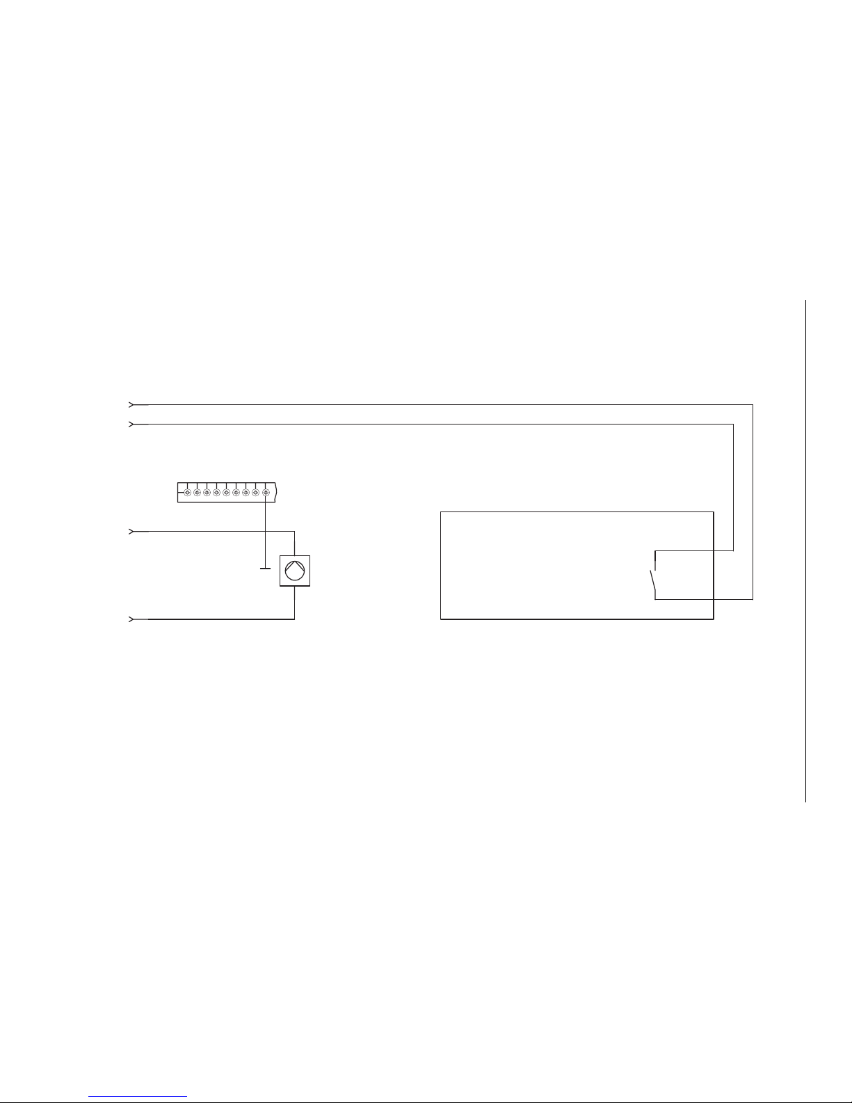
68
6. Electric Connecting Diagrams
6.3 Connection diagram for external controllers
L
N
3
Transfer/ boiler circuit pump
-P3.1
PE
Heating Zone Controller
heat demand
4 3
PE
max. rated 200W
-XE 8 external heat demand
conn. diagram/1.7B
-XE 9 external heat demand
conn. diagram/1.7B
-XE 10 L Transfer/ boiler circuit pump
conn. diagram/1.3B
-XE 11 N Transfer/ boiler circuit pump
conn. diagram/1.3B
094895/00
Page 69
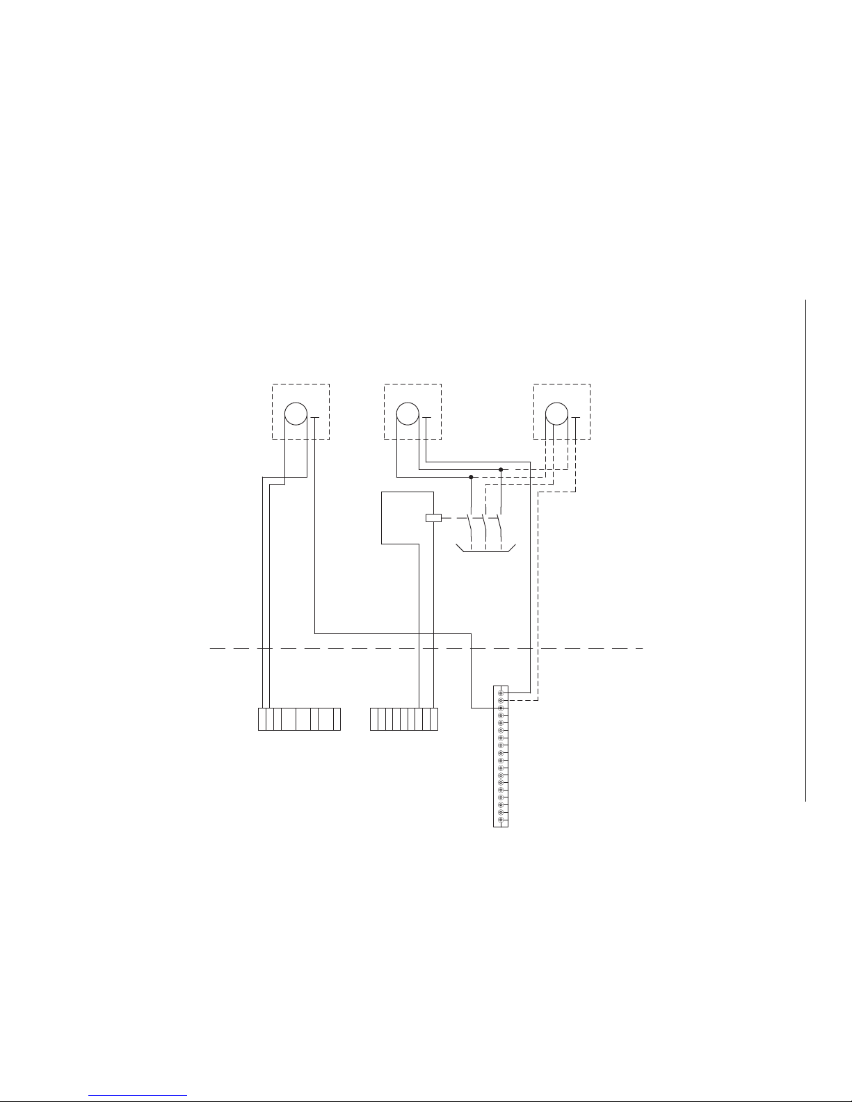
69
6. Electric Connecting Diagrams
internal
external
PE
connecting terminal
1N'2 L'
3 L'
4 N
N 5
6 L
7 L
8 CP
9 N
-XE
10 N
11
12 L
-XE
1
3 L
'
14 N
15 N'
16 lwco
17 lwco
18 LL
19 RL20 N
A2 A1
-K1*
contactor
230 V
1 2
3 4
5 6
M
PE
LNPE
-Mx.1
M
PE
L1
PE
-Mx.2
L2
N
Connection 120 V / 60 Hz
or
Connection 3 x 230 V / 60 Hz
(external feeder cable must be
laid by an electrician)
230 VAC120 VAC
M
PE
L
N
suction turbine
110 - 120 V
PE
-M12.1
Connection for buried tank mixer
* K1 = Auxiliary contactor 230 VAC by the customer
6.4 BioWIN XL pellet feed connection diagram with mixer for buried tank
Operation with a mixer must be set on the service level – see section 4.6.1 Parameters; Type of pellet feed system.
094936/00
Page 70
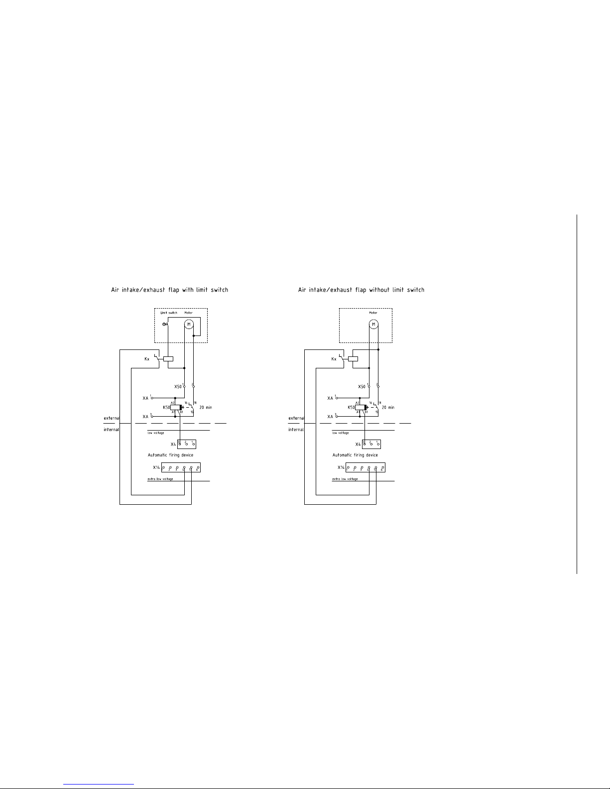
70
6. Electric Connecting Diagrams
6.5 Connection diagram for air intake/exhaust flap
The air intake/exhaust flap is directly connected to the main PCB (see basic circuit diagram 4.8) at plugs X4 (motor) and X14 (limit switch). See section 4.6.1 Parameters; Flue gas thermostat or Air intake flap.
093182/01
Page 71
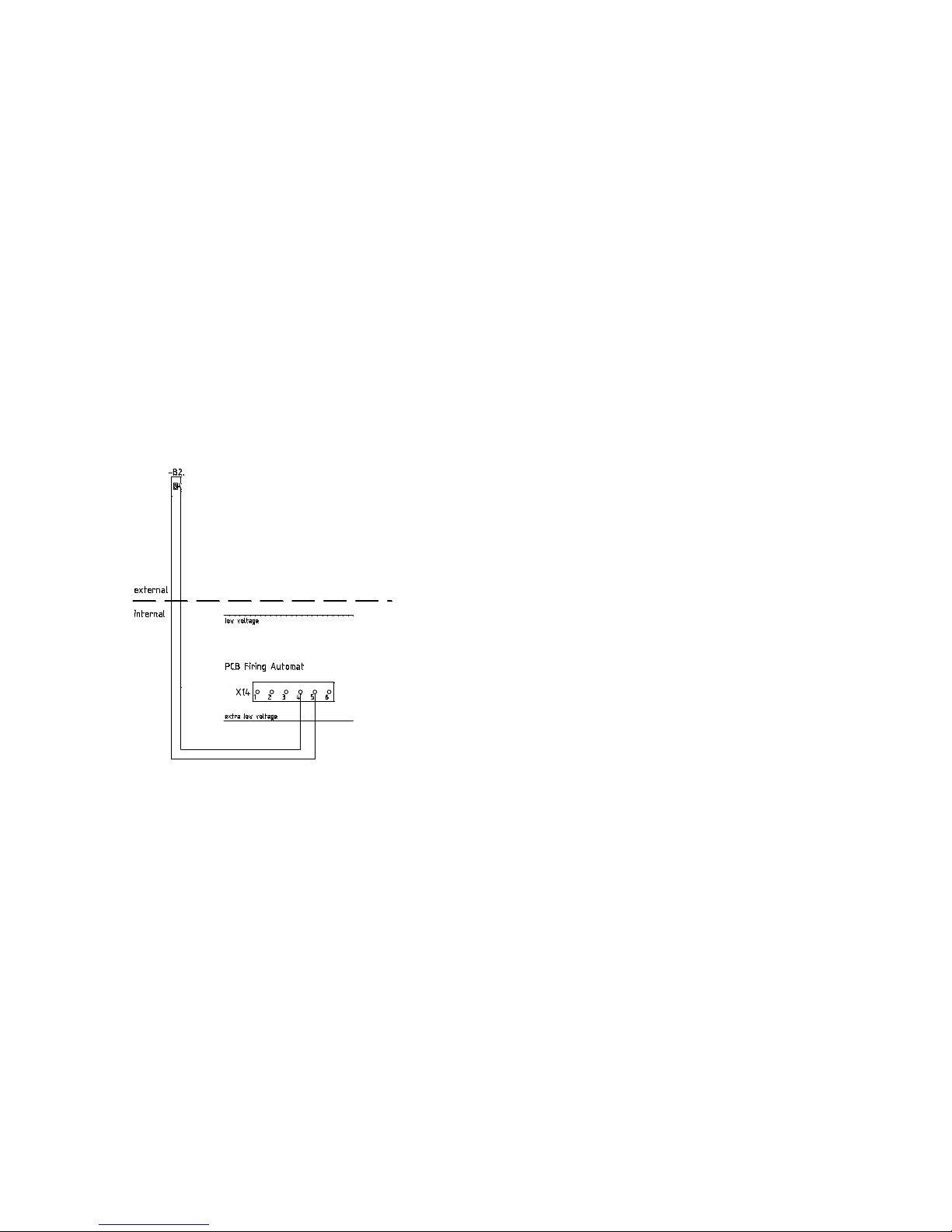
6.6 Connection diagram for flue gas thermostat
The flue gas thermostat is directly connected to the main PCB (see basic circuit diagram 4.8) at plugs X4 (motor) and X14 (limit switch). See section 4.6.1 Parameters; Flue gas thermostat or Air intake flap.
093311/00
Flue gas thermostat B2
Page 72

Subject to technical modifications. AWP-vor
Austria
Windhager Zentralheizung GmbH
Anton-Windhager-Straße 20
A-5201 Seekirchen bei Salzburg
T. +43(0)6212/2341-0
F. +43(0)6212/4228
[email protected]
www.windhager.com
 Loading...