

Windhager BioWIN 2 Operating Manual
Operating Manual
BioWIN
windhager.com
Pellet central heating boiler
Output range: 2,9 to 25,9 kW
Cascae options up to 78 kW
Pellets
xx/2012 091697/09

2
Table of contents
Table of contents
1. Important information for system operators . . . . . . . . . . . . . . . . . . . . . . . . . . . . . . . . . . . . . 4
1.1 General information . . . . . . . . . . . . . . . . . . . . . . . . . . . . . . . . . . . . . . . . . . . . . . . . . . . . . . . . . . . . . . . . . . . .4
1.1.1 Manufacturer’s obligations . . . . . . . . . . . . . . . . . . . . . . . . . . . . . . . . . . . . . . . . . . . . . . . . . . . . . . . . . . . . . . . . . . . 4
1.1.2 Installer’s obligations . . . . . . . . . . . . . . . . . . . . . . . . . . . . . . . . . . . . . . . . . . . . . . . . . . . . . . . . . . . . . . . . . . . . . . . 4
1.1.3 Operator’s obligations . . . . . . . . . . . . . . . . . . . . . . . . . . . . . . . . . . . . . . . . . . . . . . . . . . . . . . . . . . . . . . . . . . . . . . . 4
1.2 Safety precautions . . . . . . . . . . . . . . . . . . . . . . . . . . . . . . . . . . . . . . . . . . . . . . . . . . . . . . . . . . . . . . . . . . . . . .5
1.3 Sources of danger . . . . . . . . . . . . . . . . . . . . . . . . . . . . . . . . . . . . . . . . . . . . . . . . . . . . . . . . . . . . . . . . . . . . . . .5
1.3.1 Power failure (or if the blower is not running) . . . . . . . . . . . . . . . . . . . . . . . . . . . . . . . . . . . . . . . . . . . . . . . . . . . . 5
1.3.2 Burner pot . . . . . . . . . . . . . . . . . . . . . . . . . . . . . . . . . . . . . . . . . . . . . . . . . . . . . . . . . . . . . . . . . . . . . . . . . . . . . . . . . 5
1.3.3 Entering the pellet storage room, storage container . . . . . . . . . . . . . . . . . . . . . . . . . . . . . . . . . . . . . . . . . . . . . . . 6
1.4 Fuel. . . . . . . . . . . . . . . . . . . . . . . . . . . . . . . . . . . . . . . . . . . . . . . . . . . . . . . . . . . . . . . . . . . . . . . . . . . . . . . . . . .6
1.5 Start-up and maintenance . . . . . . . . . . . . . . . . . . . . . . . . . . . . . . . . . . . . . . . . . . . . . . . . . . . . . . . . . . . . . . . .7
1.6 Functional test . . . . . . . . . . . . . . . . . . . . . . . . . . . . . . . . . . . . . . . . . . . . . . . . . . . . . . . . . . . . . . . . . . . . . . . . .7
1.7 Filling the pellet store . . . . . . . . . . . . . . . . . . . . . . . . . . . . . . . . . . . . . . . . . . . . . . . . . . . . . . . . . . . . . . . . . . . 8
2. Operation . . . . . . . . . . . . . . . . . . . . . . . . . . . . . . . . . . . . . . . . . . . . . . . . . . . . . . . . . . . . . . . . . . . 9
2.1 Functional description, function elements and operating controls. . . . . . . . . . . . . . . . . . . . . . . . . . . . . . . . . . . . . . . . . . 9
2.1.1 BioWIN Klassik . . . . . . . . . . . . . . . . . . . . . . . . . . . . . . . . . . . . . . . . . . . . . . . . . . . . . . . . . . . . . . . . . . . . . . . . . . . . . 9
2.1.2 BioWIN Premium . . . . . . . . . . . . . . . . . . . . . . . . . . . . . . . . . . . . . . . . . . . . . . . . . . . . . . . . . . . . . . . . . . . . . . . . . . 10
2.1.3 BioWIN Exklusiv . . . . . . . . . . . . . . . . . . . . . . . . . . . . . . . . . . . . . . . . . . . . . . . . . . . . . . . . . . . . . . . . . . . . . . . . . . . 11
2.2 Check before initial start-up . . . . . . . . . . . . . . . . . . . . . . . . . . . . . . . . . . . . . . . . . . . . . . . . . . . . . . . . . . . . .12
2.3 Filling the reserve supply container . . . . . . . . . . . . . . . . . . . . . . . . . . . . . . . . . . . . . . . . . . . . . . . . . . . . . . .12
2.3.1 BioWIN Klassik – Manual filling . . . . . . . . . . . . . . . . . . . . . . . . . . . . . . . . . . . . . . . . . . . . . . . . . . . . . . . . . . . . . . 12
2.3.2 BioWIN Premium and Exklusiv – fully automatic filling . . . . . . . . . . . . . . . . . . . . . . . . . . . . . . . . . . . . . . . . . . . 12
2.4 InfoWINplus . . . . . . . . . . . . . . . . . . . . . . . . . . . . . . . . . . . . . . . . . . . . . . . . . . . . . . . . . . . . . . . . . . . . . . . . . . . 13
2.5 Operating modes. . . . . . . . . . . . . . . . . . . . . . . . . . . . . . . . . . . . . . . . . . . . . . . . . . . . . . . . . . . . . . . . . . . . . . .14
2.5.1 OFF mode . . . . . . . . . . . . . . . . . . . . . . . . . . . . . . . . . . . . . . . . . . . . . . . . . . . . . . . . . . . . . . . . . . . . . . . . . . . . . . . . 14
2.5.2 ON mode, lighting ON, self-test, lighting OFF . . . . . . . . . . . . . . . . . . . . . . . . . . . . . . . . . . . . . . . . . . . . . . . . . . . 14
2.5.3 Pellet feed . . . . . . . . . . . . . . . . . . . . . . . . . . . . . . . . . . . . . . . . . . . . . . . . . . . . . . . . . . . . . . . . . . . . . . . . . . . . . . . . 15
2.5.4 Solid fuel / buffer mode . . . . . . . . . . . . . . . . . . . . . . . . . . . . . . . . . . . . . . . . . . . . . . . . . . . . . . . . . . . . . . . . . . . . . 15
2.5.5 Manual operation . . . . . . . . . . . . . . . . . . . . . . . . . . . . . . . . . . . . . . . . . . . . . . . . . . . . . . . . . . . . . . . . . . . . . . . . . . 16
2.5.6 Chimney sweeper function . . . . . . . . . . . . . . . . . . . . . . . . . . . . . . . . . . . . . . . . . . . . . . . . . . . . . . . . . . . . . . . . . . . 17
2.5.7 Shut-down procedure . . . . . . . . . . . . . . . . . . . . . . . . . . . . . . . . . . . . . . . . . . . . . . . . . . . . . . . . . . . . . . . . . . . . . . . 17
2.6 Operating phases . . . . . . . . . . . . . . . . . . . . . . . . . . . . . . . . . . . . . . . . . . . . . . . . . . . . . . . . . . . . . . . . . . . . . .18
2.6.1 Standby . . . . . . . . . . . . . . . . . . . . . . . . . . . . . . . . . . . . . . . . . . . . . . . . . . . . . . . . . . . . . . . . . . . . . . . . . . . . . . . . . . 18
2.6.2 Purging . . . . . . . . . . . . . . . . . . . . . . . . . . . . . . . . . . . . . . . . . . . . . . . . . . . . . . . . . . . . . . . . . . . . . . . . . . . . . . . . . . 18
2.6.3 Ignition phase . . . . . . . . . . . . . . . . . . . . . . . . . . . . . . . . . . . . . . . . . . . . . . . . . . . . . . . . . . . . . . . . . . . . . . . . . . . . . 18
2.6.4 Flame stabilisation . . . . . . . . . . . . . . . . . . . . . . . . . . . . . . . . . . . . . . . . . . . . . . . . . . . . . . . . . . . . . . . . . . . . . . . . . 18
2.6.5 Modulation mode . . . . . . . . . . . . . . . . . . . . . . . . . . . . . . . . . . . . . . . . . . . . . . . . . . . . . . . . . . . . . . . . . . . . . . . . . . 18
2.6.6 Burnout . . . . . . . . . . . . . . . . . . . . . . . . . . . . . . . . . . . . . . . . . . . . . . . . . . . . . . . . . . . . . . . . . . . . . . . . . . . . . . . . . . 18
2.6.7 Burner OFF . . . . . . . . . . . . . . . . . . . . . . . . . . . . . . . . . . . . . . . . . . . . . . . . . . . . . . . . . . . . . . . . . . . . . . . . . . . . . . . 18

3
Table of contents
2.7 Information text . . . . . . . . . . . . . . . . . . . . . . . . . . . . . . . . . . . . . . . . . . . . . . . . . . . . . . . . . . . . . . . . . . . . . . .19
2.7.1 Next boiler cleaning . . . . . . . . . . . . . . . . . . . . . . . . . . . . . . . . . . . . . . . . . . . . . . . . . . . . . . . . . . . . . . . . . . . . . . . . 19
2.7.2 Operating hours . . . . . . . . . . . . . . . . . . . . . . . . . . . . . . . . . . . . . . . . . . . . . . . . . . . . . . . . . . . . . . . . . . . . . . . . . . . 20
2.7.3 Pellet consumption total . . . . . . . . . . . . . . . . . . . . . . . . . . . . . . . . . . . . . . . . . . . . . . . . . . . . . . . . . . . . . . . . . . . . 20
2.7.4 Flue gas temperature . . . . . . . . . . . . . . . . . . . . . . . . . . . . . . . . . . . . . . . . . . . . . . . . . . . . . . . . . . . . . . . . . . . . . . . 20
2.7.5 Boiler temperature setpoint . . . . . . . . . . . . . . . . . . . . . . . . . . . . . . . . . . . . . . . . . . . . . . . . . . . . . . . . . . . . . . . . . 20
2.7.6 Current boiler output . . . . . . . . . . . . . . . . . . . . . . . . . . . . . . . . . . . . . . . . . . . . . . . . . . . . . . . . . . . . . . . . . . . . . . . 20
2.7.7 Switch/buffer temperature . . . . . . . . . . . . . . . . . . . . . . . . . . . . . . . . . . . . . . . . . . . . . . . . . . . . . . . . . . . . . . . . . . . 20
2.7.8 Display module software version . . . . . . . . . . . . . . . . . . . . . . . . . . . . . . . . . . . . . . . . . . . . . . . . . . . . . . . . . . . . . . 21
2.7.9 Firing automate software version . . . . . . . . . . . . . . . . . . . . . . . . . . . . . . . . . . . . . . . . . . . . . . . . . . . . . . . . . . . . . 21
2.7.10 Boiler model . . . . . . . . . . . . . . . . . . . . . . . . . . . . . . . . . . . . . . . . . . . . . . . . . . . . . . . . . . . . . . . . . . . . . . . . . . . . . . 21
2.8 Menu guide . . . . . . . . . . . . . . . . . . . . . . . . . . . . . . . . . . . . . . . . . . . . . . . . . . . . . . . . . . . . . . . . . . . . . . . . . . . 22
2.8.1 Operator level . . . . . . . . . . . . . . . . . . . . . . . . . . . . . . . . . . . . . . . . . . . . . . . . . . . . . . . . . . . . . . . . . . . . . . . . . . . . . 24
2.8.2 Service level . . . . . . . . . . . . . . . . . . . . . . . . . . . . . . . . . . . . . . . . . . . . . . . . . . . . . . . . . . . . . . . . . . . . . . . . . . . . . . 38
2.9 Heating system operation . . . . . . . . . . . . . . . . . . . . . . . . . . . . . . . . . . . . . . . . . . . . . . . . . . . . . . . . . . . . . . . 39
2.9.1 BioWIN with MESplus system control . . . . . . . . . . . . . . . . . . . . . . . . . . . . . . . . . . . . . . . . . . . . . . . . . . . . . . . . . . 39
2.9.2 BioWIN with REG standard control . . . . . . . . . . . . . . . . . . . . . . . . . . . . . . . . . . . . . . . . . . . . . . . . . . . . . . . . . . . . 40
3. Care, cleaning and maintenance . . . . . . . . . . . . . . . . . . . . . . . . . . . . . . . . . . . . . . . . . . . . . . 42
3.1 Overview of intervals between cleaning (maintenance) . . . . . . . . . . . . . . . . . . . . . . . . . . . . . . . . . . . . . . .42
3.2 Cleaning and operating implements . . . . . . . . . . . . . . . . . . . . . . . . . . . . . . . . . . . . . . . . . . . . . . . . . . . . . .43
3.3 Care of cladding and keyboard foil . . . . . . . . . . . . . . . . . . . . . . . . . . . . . . . . . . . . . . . . . . . . . . . . . . . . . . . .43
3.4 Cleaning heating surfaces (BioWIN Klassik and Premium) . . . . . . . . . . . . . . . . . . . . . . . . . . . . . . . . . . . . . . . . .43
3.5 Emptying the ash pan (BioWIN Klassik and Premium) . . . . . . . . . . . . . . . . . . . . . . . . . . . . . . . . . . . . . . . .44
3.6 Emptying ash container (BioWIN Exklusiv) . . . . . . . . . . . . . . . . . . . . . . . . . . . . . . . . . . . . . . . . . . . . . . . . .44
3.7 Combustion chamber . . . . . . . . . . . . . . . . . . . . . . . . . . . . . . . . . . . . . . . . . . . . . . . . . . . . . . . . . . . . . . . . . . 46
3.7.1 Baffle plate, thermocontrol sensor, down chute . . . . . . . . . . . . . . . . . . . . . . . . . . . . . . . . . . . . . . . . . . . . . . . . . 46
3.7.2 Burner pot . . . . . . . . . . . . . . . . . . . . . . . . . . . . . . . . . . . . . . . . . . . . . . . . . . . . . . . . . . . . . . . . . . . . . . . . . . . . . . . . 47
3.8 Blower wheel, blower box . . . . . . . . . . . . . . . . . . . . . . . . . . . . . . . . . . . . . . . . . . . . . . . . . . . . . . . . . . . . . . . 49
3.9 Exhaust pipe to flue . . . . . . . . . . . . . . . . . . . . . . . . . . . . . . . . . . . . . . . . . . . . . . . . . . . . . . . . . . . . . . . . . . . .50
3.10 Water tank level . . . . . . . . . . . . . . . . . . . . . . . . . . . . . . . . . . . . . . . . . . . . . . . . . . . . . . . . . . . . . . . . . . . . . . .50
3.11 Cleaning supply container (BioWIN Klassik, Premium and Exklusiv) and
feed unit flap (BioWIN Premium and Exklusiv) . . . . . . . . . . . . . . . . . . . . . . . . . . . . . . . . . . . . . . . . . . . . . .51
3.12 Pellet storage room or storage container (BioWIN Premium and Exklusiv) . . . . . . . . . . . . . . . . . . . . . .52
4. Troubleshooting . . . . . . . . . . . . . . . . . . . . . . . . . . . . . . . . . . . . . . . . . . . . . . . . . . . . . . . . . . . . 53
4.1 No display on InfoWINplus . . . . . . . . . . . . . . . . . . . . . . . . . . . . . . . . . . . . . . . . . . . . . . . . . . . . . . . . . . . . . . .54
4.2 IN- messages . . . . . . . . . . . . . . . . . . . . . . . . . . . . . . . . . . . . . . . . . . . . . . . . . . . . . . . . . . . . . . . . . . . . . . . . .54
4.3 FE- messages . . . . . . . . . . . . . . . . . . . . . . . . . . . . . . . . . . . . . . . . . . . . . . . . . . . . . . . . . . . . . . . . . . . . . . . . .54
4.4 AL – messages . . . . . . . . . . . . . . . . . . . . . . . . . . . . . . . . . . . . . . . . . . . . . . . . . . . . . . . . . . . . . . . . . . . . . . . . 56
5. EG-Declaration of conformity . . . . . . . . . . . . . . . . . . . . . . . . . . . . . . . . . . . . . . . . . . . . . . . . . 59
Guarantee and warranty limitations . . . . . . . . . . . . . . . . . . . . . . . . . . . . . . . . . . . . . . . . . . . . . . 60

4
1. Important information for system operators
1. Important information for system operators
Dear Heating System Owners,
We would like to congratulate you on your new environmentally friendly boiler system. With the purchase of this
high-quality product by Windhager, you have selected a system that provides more comfort and optimised fuel
consumption while utilising an environmentally friendly means of saving resources. Your boiler was manufactured
under strict ISO 9001 certified standards, was subjected to extensive tests and all its components are recyclable.
On the following pages we have provided specific information and important tips regarding system operation, unit
functions and cleaning. Please pay close attention to these instructions. Familiarity with the material in this document will allow you to enjoy long-term operation of the unit. We wish you all the best with your Windhager boiler!
1.1 General information
1.1.1 Manufacturer’s obligations
Our products are manufactured in accordance with the essential requirements of the various applicable guidelines. They therefore carry the
-label and are supplied with all the required documentation.
Technical details subject to change.
We as the manufacturer cannot be held liable in the following cases:
– Incorrect use of the unit
– Failure to perform proper maintenance
– Incorrect installation of the unit
1.1.2 Installer’s obligations
The installer is the person responsible for installing the unit. The installer must comply with the following
instructions:
– Read and follow all instructions supplied with the unit.
– Carry out installation in accordance with the applicable standards and specifications.
– Explain to the operator how the system works.
– Make the operator aware of his obligation to inspect and maintain the unit.
– Hand over all operating instructions to the operator.
1.1.3 Operator’s obligations
To ensure that the unit gives optimum service, the operator must follow these instructions:
– Read and follow the instructions in the operating manual.
– Installation and commissioning must be performed by appropriately qualified technicians.
– Make sure the installer explains how the system works.
– Perform all the necessary checks and maintenance.
– Keep the manuals in good condition and store them near the unit.
This unit is not intended for use by persons (including children) who have physical or mental disabilities or sensory
impairment or who have no experience or knowledge of the correct use of the unit, unless supervised or trained
by a person responsible for their safety. Children should be supervised to ensure they do not play with the unit.
5
1. Important information for system operators
1.2 Safety precautions
The boiler and related accessories are state of the art and meet all applicable safety regulations and operate
using 230 V AC electrical current. Improper installation or repair can pose the danger of life-threatening electrical
shock. Installation may be performed only by appropriately qualified technicians.
Caution symbols
Please take careful note of the following symbols in this Operating Manual.
Attention!
Ignoring the warnings identified can lead to personal injury.
Information!
Ignoring the warnings identified can lead to malfunction of, or damage to the boiler or heating system.
Note!
The blocks of text highlighted provide information and tips for operation.
1.3 Sources of danger
1.3.1 Power failure (or if the blower is not running)
Attention!
Do not open the combustion chamber door, there is an increased risk of deflagration when opening
the combustion chamber door. A self-test is performed following a power failure during combustion
and then operation is continued automatically.
1.3.2 Burner pot
Attention!
Never fill the burner pot with pellets by hand. Excessive combustion material in the burner pot means that the pellets will not be ignited optimally. Too much low temperature carburisation gas will
be generated and this can lead to deflagration.

6
1. Important information for system operators
1.3.3 Entering the pellet storage room, storage container
All energy sources are subject to safety regulations which must be observed when working with fuels, heating
systems and storage rooms. This also applies to the storage of pellets.
After the storage room is filled, odourless carbon monoxide (CO) may be produced and there may be insufficientoxygen. For this reason, do not enter the pellet storage room for 6 weeks after it has been filled. Only trained
persons may enter the storage room for the purpose of measuring gas levels.
Please also follow the instructions on the sticker:
– No access to unauthorised persons, keep children away from the pellet store!
– Ensure sufficient ventilation before entering. Keep the door open while inside.
– Only enter the storage room under the supervision of a second person standing outside.
– No smoking, flames or other sources of ignition are permitted.
– Risk of injury from moving parts.
– Pellet boilers must be switched off at least 15 minutes before filling.
– Fill in accordance with the instructions of the boiler and pellet suppliers.
– Protect pellets from damp.
If you feel unwell, leave the storage room immediately and seek medical advice.
Attention!
Do not attempt to enter an unaired storage room (particularly buried tanks).
1.4 Fuel
To ensure that your new heating system provides long-term reliable service, the following must be observed:
Quality of pellets must be in accordance with EN 14961-2 A1:
The quality of the pellets is an important factor in achieving optimum operation of the heating system. When
buying pellets, make sure that they meet the quality standards of EN 14961-2 A1 (or ÖNORM M7135 / DINplus).
For maximum reliability, source pellets from manufacturers with EN-Plus certification (or DIN-Plus, ÖNORM
M7135 or UZ38), as they are required to perform ongoing internal quality control.
Make your pellet supplier aware of these quality requirements before ordering and seek confirmation upon
delivery.
Consequences of quality fluctuations:
Pellets are 100% unprocessed wood, so minor fluctuations in fuel quality are normal and reflect the natural origins of the material. These quality fluctuations affect the level of dirt, the ash content and therefore the cleaning
intervals.
A reduction in cleaning intervals due to fluctuations in pellet quality cannot be remedied as part of a repair under
guarantee!

7
1. Important information for system operators
1.5 Start-up and maintenance
Please permit Windhager Customer Service or have one of our customer service Partners put your new boiler into
service. In this way, all functions of the new unit will be thoroughly checked; you will also benefit from the detailed
information provided by the system installer. Installation by a qualified technician as well as the maintenance
required by the guarantee limitations and undertaken by Windhager Customer Service or a customer service
partner will guarantee the optimal use and service life of your boiler system. This is the only way to assure the
benefits of this technologically advanced boiler and guarantee safe, environmentally friendly and energy-saving
system operation.
The following preconditions must be met before you order the initial start-up:
1.) Boiler installed correctly.
2.) System fully wired up electrically.
3.) System rinsed, filled and vented – heat consumption must be possible.
4.) Boiler connected to domestic water and filled.
5.) Sufficient quantity of fuel available (pellets, split logs, oil or gas).
6.) The customer must be present during start-up.
The initial start-up cannot be carried out if any of these points are neglected. The customer will be charged for
any unnecessary costs arising as a result.
Start-up and maintenance by Windhager Customer Service or a customer service partner are part of the guarantee requirements of the enclosed “guarantee limitations”.
Note!
During the first few weeks after start-up, condensation can occur in the combustion chamber, ash
pan and on the heating surfaces. This has no effect on the function and service life of the boiler.
1.6 Functional test
EN 12828 and ÖNORM B8131 require that the function of the system and related safety equipment be checked
and certified yearly by a qualified technician (installer, heating system contractor).
At two-year intervals, the heating water condition must be checked (ÖNORM H 5195-1) by a heating expert (installer) (see BioWIN assembly instructions – Heating water); this is to prevent corrosion and sediment accumulation in
the heating system and boiler. For systems using more than 1,500 litres of water (e.g., systems with accumulator
tanks), this inspection is required on an annual basis.
In the event of repair work requiring a change of water in the heating system, the heating water is to be checked
within 4 to 6 weeks after such work.
Corrosion and sediment resulting from improper heating water are not covered by the guarantee and warranty.
8
1. Important information for system operators
Pressing one of the six buttons firstly switches just the lighting and display on. The boiler is only switched off
when the button is pressed for the 2nd time. Wait until burnout mode has finished (not indicated on the display)
and open the combustion chamber doors.
During filling, negative pressure is created in the pellet store and this can cause burn-back in the pellet boiler.
Therefore, the boiler must be stopped from operating during the filling procedure.
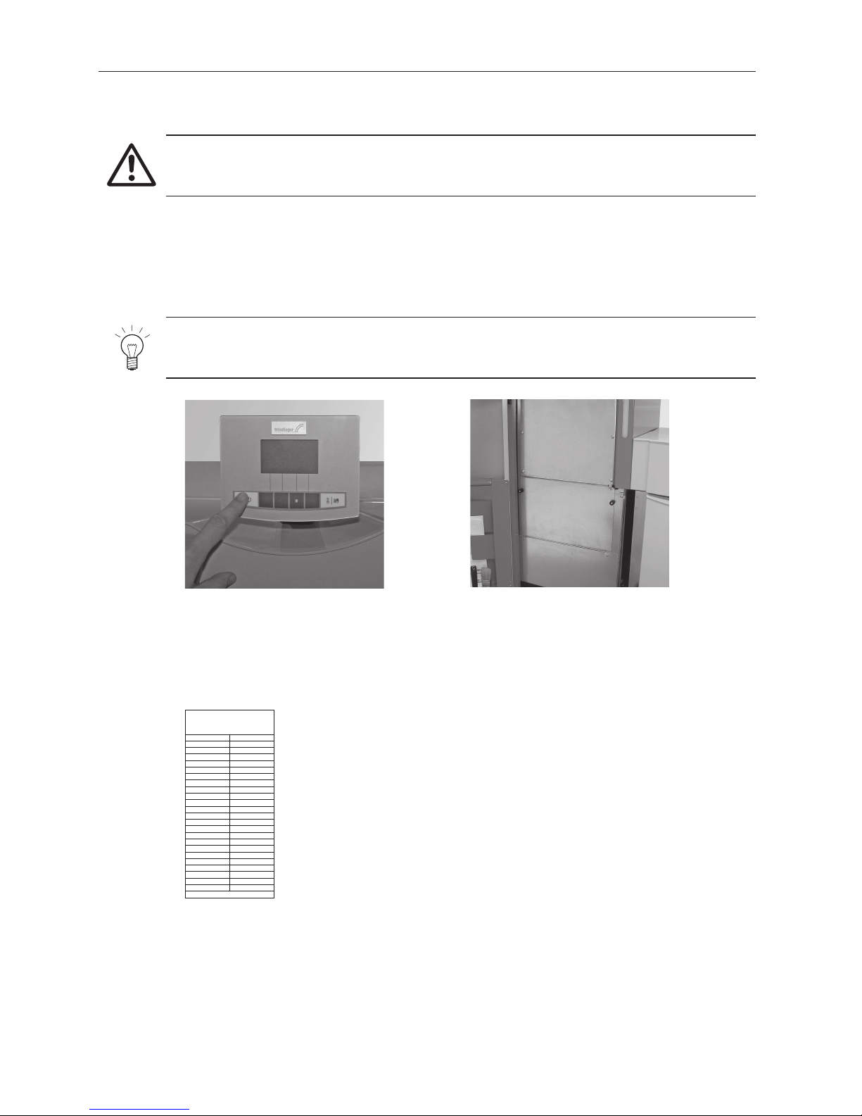
Attention!
The pellet flue-connected stove must be switched off correctly at least 15 minutes before the store
is filled – Fig. 2. Press the ON/OFF button. Never switch off using the emergency OFF switch!
Tip!
To prevent negative pressure arising in the pellet boiler, remove the inspection cover (Fig. 3) and
leave open during the filling process.
Fig. 2 Switching off BioWIN
Fig. 3 Opening inspection cover during
the filling process
002357/00 01/2010
Befüllung Lagerraum
Filling date and volume
Remplissage du silo de stockage
Datum/Date/Date
Menge/Volume/Quantité
kg
kg
kg
kg
kg
kg
kg
kg
kg
kg
kg
kg
kg
kg
kg
kg
kg
kg
kg
kg
kg
kg
kg
Fig. 4 „Storage room fill“ sticker on the
storage room door
Every storage room fill should be documented by adding the date and volume to the „Storage room fill“ sticker –
Fig. 4.
1.7 Filling the pellet store
9
2. Operation
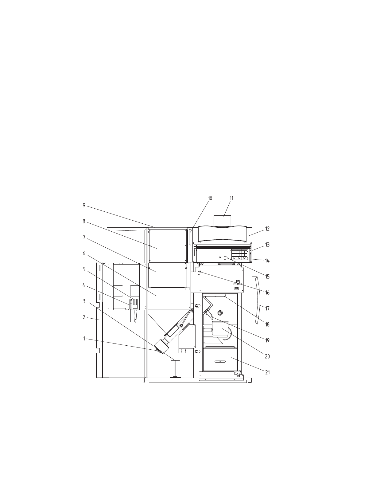
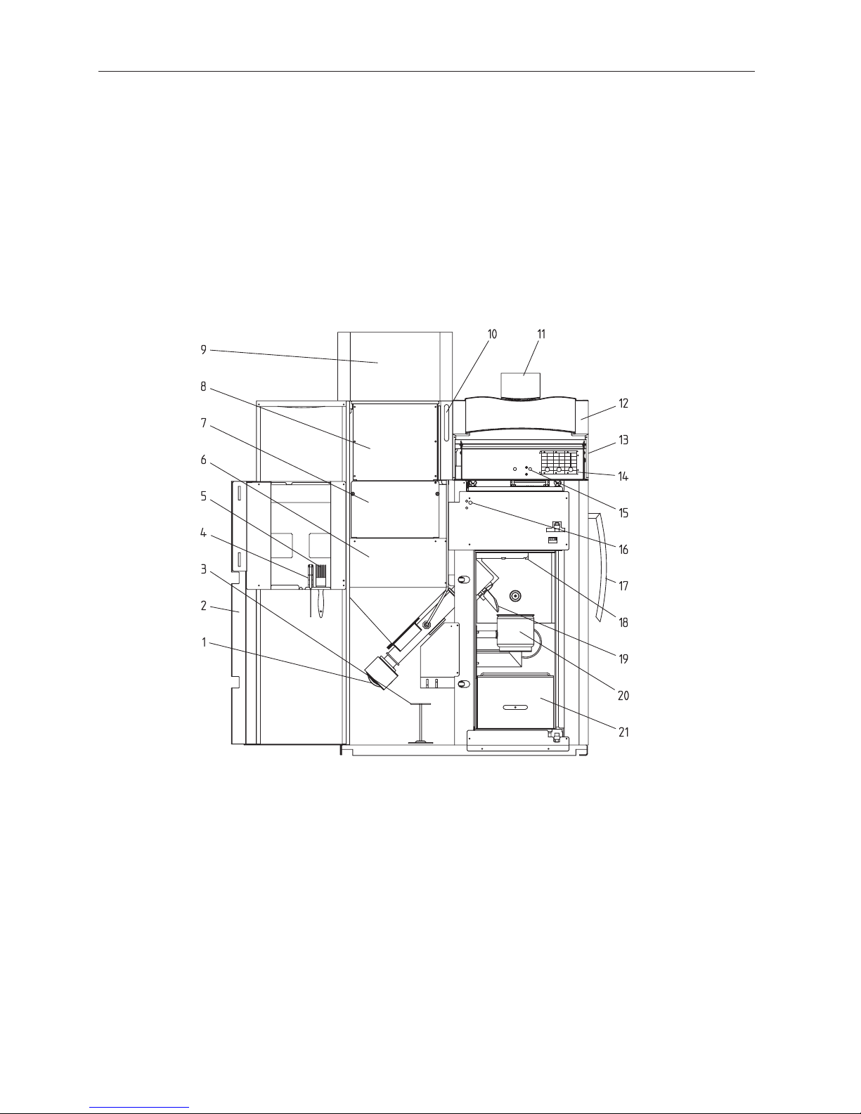
Fig. 5 BioWIN Klassik without combustion chamber door and with open cladding door
2. Operation
2.1 Functional description, function elements and
operating controls
The BioWIN pellet boiler and the Modular Energy System MES or the REG standard control combine to form a
perfect unit. The BioWIN automatically fires when the control system signals a heating requirement. Following
“purging” (safety function), ignition starts and the pellet metering auger switches on. The burner pot is automatically filled with pellets. When flame formation has been detected (thermocontrol sensor), the boiler enters flame
stabilisation mode and then control mode (modulation mode) and keeps to the specified boiler temperature setpoint (between 60 °C and 75 °C). The boiler enters burnout mode if the heat consumed drops below the minimum
nominal thermal output or no heating requirement is signalled by the control system. The blower continues to run
until the burner pot has cooled down.
2.1.1 BioWIN Klassik
The reserve supply container is loaded by hand. The heating surfaces are cleaned manually using the cleaning
lever. The cleaning residues from the heating surfaces and the combustion residues from the burner pot drop into
the ash pan.
1 ........... Auger motor
2 ........... Cladding door
3 ........... Cleaning tool/cone removal tool
4 ........... Spatula
5 ........... Cleaning brush
6 ........... Pellet reserve supply container
7 ........... Inspection cover, bottom
8 ........... Inspection cover, top
9 ........... Cover for pellet reserve supply container
10 ......... Level indicator for water tank
11 ......... InfoWINplus operating unit
12 ......... Cladding cover, at front
13 ......... Cladding cover, at rear
14 ......... MES modules
15 ......... Safety thermostat for boiler temperature
16 ......... Safety thermostat for auger tube
17 ......... Lever for cleaning heating surfaces
18 ......... Baffle plate
19 ......... Down chute
20 ......... Burner pot
21 ......... Ash pan
10
2. Operation
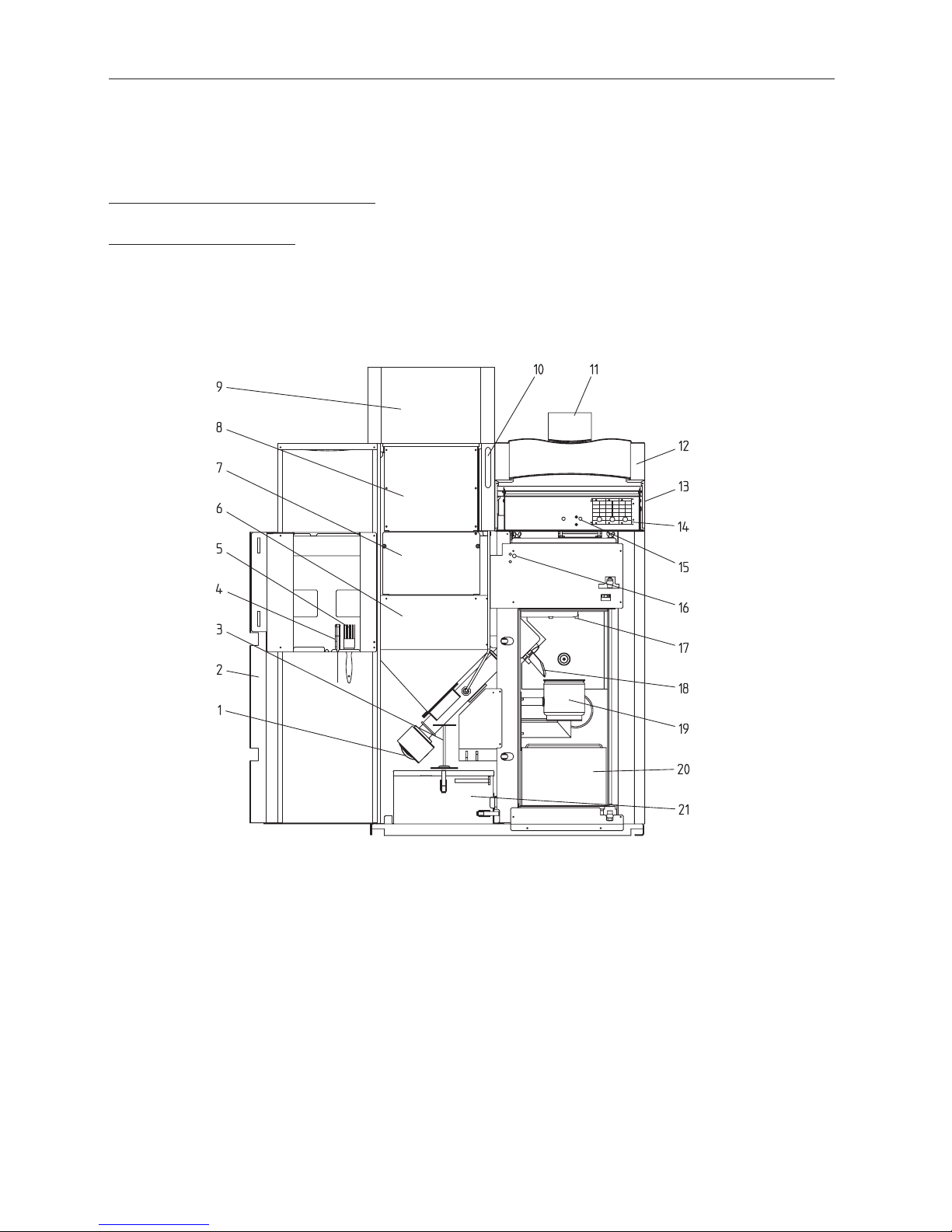
2.1.2 BioWIN Premium
Version as BioWIN Klassik, but in addition with fully automatic pellet feed
The pellet feed uses a maintenance-free suction turbine to fill the BioWIN reserve supply container fully automatically with pellets from a pellet storage room or storage container. The pellet feed is switched on by the lower fill
level switch (proximity switch) in the reserve supply container or at the end of the enable time or the beginning
of the start time, and runs for as long as the reserve supply container is full. Filling is not started if the boiler is
in heating operation or the feed has been blocked by the control unit (not during the enable time e.g. at night). If
the boiler is operating when filling is necessary, the boiler switches to burnout mode.
Switching between suction probes 1, 2 and 3 is fully automatic. The system changes to the next suction probe after
the reserve supply container has been filled a certain number of times. This means the storage room is evenly
emptied to a large extent.
Fig. 6 BioWIN Premium without combustion chamber door and with open cladding door
1 ........... Auger motor
2 ........... Cladding door
3 ........... Cleaning tool/cone removal tool
4 ........... Spatula
5 ........... Cleaning brush
6 ........... Pellet reserve supply container
7 ........... Inspection cover, bottom
8 ........... Inspection cover, top
9 ........... Fully automatic pellet feed
10 ......... Level indicator for water tank
11 ......... InfoWINplus operating unit
12 ......... Cladding cover, at front
13 ......... Cladding cover, at rear
14 ......... MES modules
15 ......... Safety thermostat for boiler temperature
16 ......... Safety thermostat for auger tube
17 ......... Lever for cleaning heating surfaces
18 ......... Baffle plate
19 ......... Down chute
20 ......... Burner pot
21 ......... Ash pan
11
2. Operation
2.1.3 BioWIN Exklusiv
Version as BioWIN Premium, but in addition with fully automatic heating surface cleaning and ash
removal
Fully automatic heating surface cleaning:
A motor moves the heating surface cleaning system vertically and the heating surfaces remain clean.
Fully automatic ash removal:
During fully automatic ash removal, the ash is transported out of the combustion chamber and the heating surfaces in the side ash container under the supply container using a motor and auger. Pellets only have a low ash
content (approx. 0.5 %). The container therefore only needs emptying 1–4 times a year.
Fig. 7 BioWIN Exklusiv without combustion chamber door and with open cladding door
1 ........... Auger motor
2 ........... Cladding door
3 ........... Cleaning tool/cone removal tool
4 ........... Spatula
5 ........... Cleaning brush
6 ........... Pellet reserve supply container
7 ........... Inspection cover, bottom
8 ........... Inspection cover, top
9 ........... Fully automatic pellet feed
10 ......... Level indicator for water tank
11 ......... InfoWINplus operating unit
12 ......... Cladding cover, at front
13 ......... Cladding cover, at rear
14 ......... MES modules
15 ......... Safety thermostat for boiler temperature
16 ......... Safety thermostat for auger tube
17 ......... Baffle plate
18 ......... Down chute
19 ......... Burner pot
20 ......... Ash deflector
21 ......... Ash container

12
2. Operation
2.2 Check before initial start-up
a) System pressure (heating water pressure)
The system must be filled and vented. With the system cold, pressure should be at least 1.0 bar (maximum 1.8
bar). If you have any questions, your installer will gladly answer them.
b) Ventilation
Please make sure the boiler room is well ventilated. The air supply must be as free of dust as possible.
c) Flue
Please have the chimney sweep check the flue, and, if necessary, clean it.
d) Water tank
For level check in water tank for burn-back safeguard – see page 47.
2.3 Filling the reserve supply container
2.3.1 BioWIN Klassik – Manual filling
Open reserve supply container cover and fill reserve container up to max. 1 cm below the edge. Close the cover.
2.3.2 BioWIN Premium and Exklusiv – fully automatic filling
The reserve supply container is filled by the fully automatic pellet feed. Windhager Customer Service or the customer service Partner will perform the first fill (start-up), take the boiler and its pellet supply into service and
familiarise the customer with the operation and cleaning of the boiler, with reference to the Operating Manual.
13
2. Operation
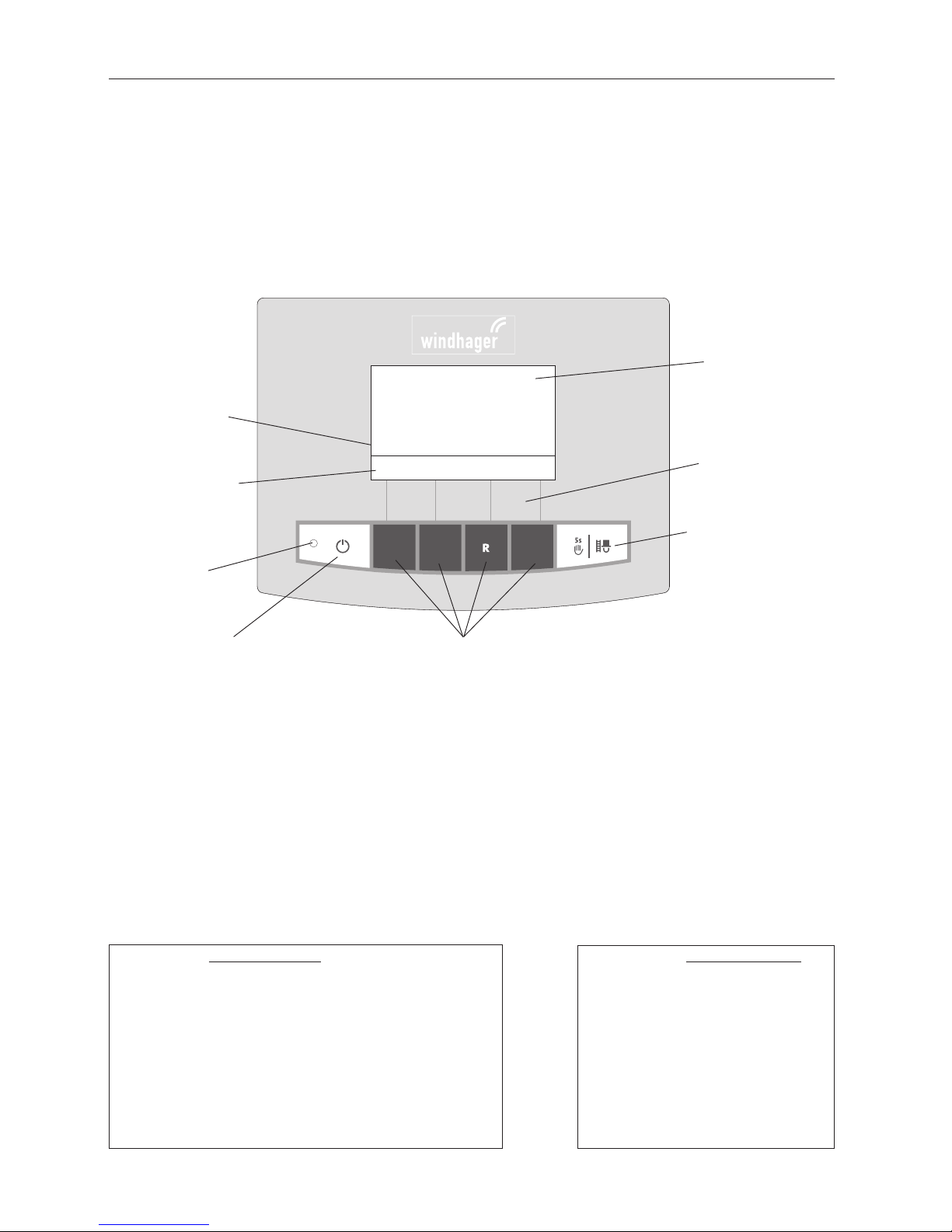
2.4 InfoWINplus
The InfoWINplus is a central operating and display unit for boilers and for modules of the MESplus system control
(see separate instructions).
It consists of a large full text display, an ON/OFF button with an LED signal lamp indicating Operation (green) or
Malfunction (red), a button for manual operation / flue cleaning function as well as four individual menu buttons.
The function of each menu button is displayed on the Menu line.
Fig. 8 InfoWINplus
The various operating modes are displayed on InfoWINplus together with the corresponding operating phases.
Kesseltemperatur
Standby
Info Menü
38
°C
Operating phases are
displayed here, including Standby, Burner
OFF, etc.
Menu line
Signal lamp (LED)
“Operation” green
Full-text display
(illuminated display)
Assignment of buttons to
their specific function
Manual operation and
Chimney sweeper function
ON/OFF button Menu buttons
The following operating modes exist:
– OFF
– ON (with self-test, lighting ON, lighting OFF)
– Pellet feed
– Solid fuel / buffer mode
– Manual operation
– Chimney sweeper function
– Shut-down procedure
Corresponding operating phases:
– Standby, display OFF
– Purging
– Ignition phase
– Flame stabilisation
– Modulation mode
– Burnout
– Burner OFF
– Switch off heat generator
è
Colours of backlit display:
– White: Normal operation
– Pink: Information and fault messages
– Red: Alarm message
14
2. Operation
2.5 Operating modes
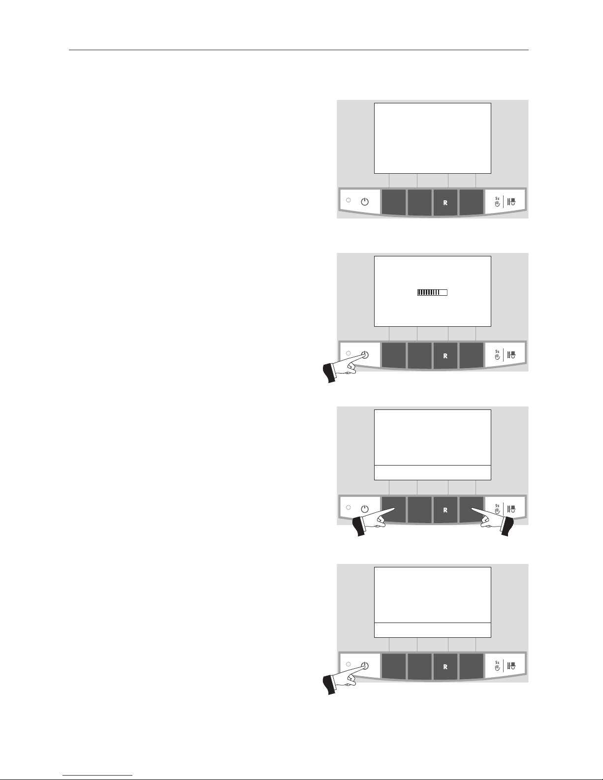
2.5.1 OFF mode
The boiler is switched off when in OFF mode. The display
and all buttons, with the exception of the ON/OFF button, do not function. The LED on the InfoWINplus does
not light up – Fig. 9.
Fig. 9 OFF mode
Fig. 10 Self-test
Self-test
active
Fig. 11 Standard display
Boiler temperature
(Operating phases)
Info Menu
42
°C
Fig. 12 Display lighting ON
Boiler temperature
(Operating phases)
Lighting ON
42
°C
(Animated symbol)
2.5.2 ON mode, lighting ON, self-test,
lighting OFF
Press the ON/OFF button, lighting and display are switched
on and the self-test starts automatically – Fig. 10.
Self-test:
Sensors, switches and motors are checked during the selftest.
After a successful self-test, the display shows an operating
phase and the boiler water temperature (standard display).
The LED control lamp lights up green and the desired functions can be selected using the buttons – Fig. 11.
If the self-test was unsuccessful, an information message
(e.g. information, fault, alarm) is displayed (see sections 4).
Lighting ON/OFF
The display lighting switches off automatically after 10 min.
(Fig. 12). Pressing one of the six buttons switches the lighting on again for 10 min.
InfoWINplus identifies and stores the various operating modes and states. Once the system is switched on, other operating modes may also be displayed instead of the standard
display, such as manual operation, solid fuel or accumulator tank operation; malfunctions are also displayed. These
operating modes and states are described later in these instructions.

15
2. Operation
Fig. 13
Pellet feed
Burnout
Info Menu
42
°C
2.5.3 Pellet feed
Pellet feed – burnout
Pellet feed from the storage room into the reserve supply container has been
requested. Combustion is stopped.
Pellet transport into the burner pot is stopped, the Induced draught fan continues to run until all the remaining pellets have been burned and the burner pot
has cooled down – Fig. 13.
Pellet feed in operation
The pellet feed is in operation. Pellets are supplied from the storage room into
the reserve supply container. The burner is locked – Fig. 14.
Fig. 14
Pellet feed
in operation
Burner locked
Info Menu
42
°C
2.5.4 Solid fuel / buffer mode
If the BioWIN pellet boiler is combined with a solid fuel boiler or an accumulator
tank, the WVF or B-PLM module integrated in the control panel automatically
switches over between pellet and solid fuel/buffer mode.
Combustion of the BioWIN is stopped when the WVF or B-PLM module sends
the request to switch over to solid fuel/buffer mode – Fig. 15.
Following this, the system switches over to solid fuel/buffer mode and the BioWIN burner is locked – Fig. 16.
If the pellet boiler is switched off using the ON/OFF button on the InfoWINplus,
an automatic switchover to solid fuel/buffer mode is performed in conjunction
with a WVF module. Once the InfoWINplus unit is switched on, the pellet boiler
can be locked out for a maximum of 15 minutes due to switch-over delays. This
is displayed by InfoWINplus – Fig. 16.
After an hour in solid fuel/buffer mode, the display is shut down fully, only the
green LED is lit up. The display is switched back on by pressing a button or when
there is a heating requirement.
Fig. 15
Solid fuel/ buffer mode
Burnout
Info Menu
42
°C
Fig. 16
Solid fuel/buffer mode
Burner locked
Info Menu
42
°C
16
2. Operation
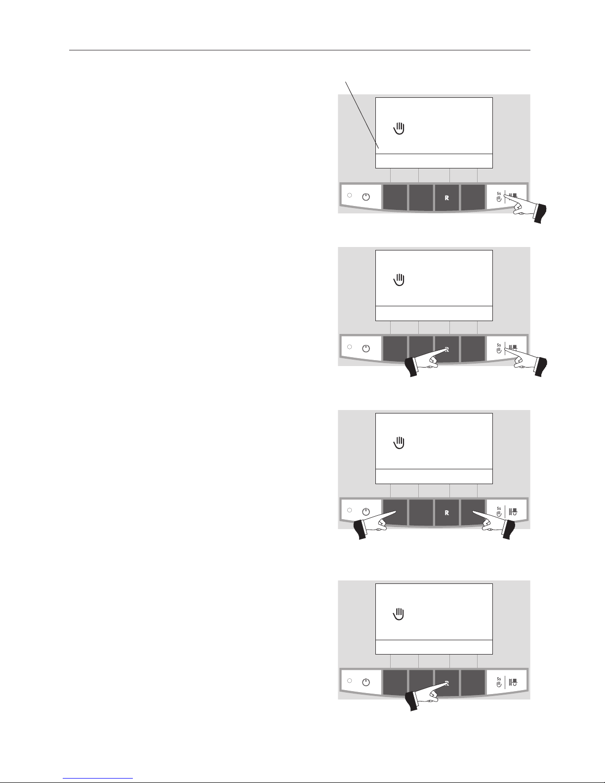
2.5.5 Manual operation
Note!
Manual operation cannot be started in “solid fuel/buffer
mode”. Manual operation must not be started if an installed
solid fuel boiler is operating (heated up). Manual operation
may be started if there is no solid fuel boiler installed or if this
is not operating but only the accumulator tank is active. In this
case, first set the operating mode switch on the WVF+ to relay
test 2 or on the B-PLM+ to relay test 1 (see WVF+ or B-PLM+
operating manual).
Fig. 17
Manual operation
Boiler temperature
(Operating phases)
– Cancel +
42
°C
Pressing one of the six buttons switches the lighting and
display on. Manual operation starts if the Manual operati-
on / chimney sweeper function button is pressed for more
than five seconds – Fig. 17. This sets the boiler temperature to the setpoint fixed for manual operation (standard
value 60 °C). The current automatic setting is not affected
by this. The lighting is switched off after the lighting timer
has counted down (10 min.); the function or display remains
unchanged.
Pressing the Cancel button or Manual operation / chimney
sweeper function button terminates the function – Fig. 18.
The boiler returns to automatic operation.
Setpoint adjustment for manual operation
By pressing the + or – button the display switches to the
setpoint adjustment mode – Fig. 19. Using the + or – button
can change the setpoint in 1 K steps. The temperature set
in this mode is not permanently saved. The original set temperature is used once manual operation ends.
(Symbol flashes)
5 sec. drücken
Fig. 18
Manual operation
Boiler temperature
(Operating phases)
– Cancel +
42
°C
(Symbol flashes)
Fig. 19
Manual operation
Boiler temperature
– Back +
70
°C
(Symbol flashes)
Fig. 20
Manual operation
Boiler temperature
– Back +
70
°C
(Symbol flashes)
The various operating phases are displayed here,
including Burner in operation, Burner OFF, etc.
After pushing the Back button (Fig. 20) or after waiting
45seconds, the screen returns to its previous display.
17
2. Operation
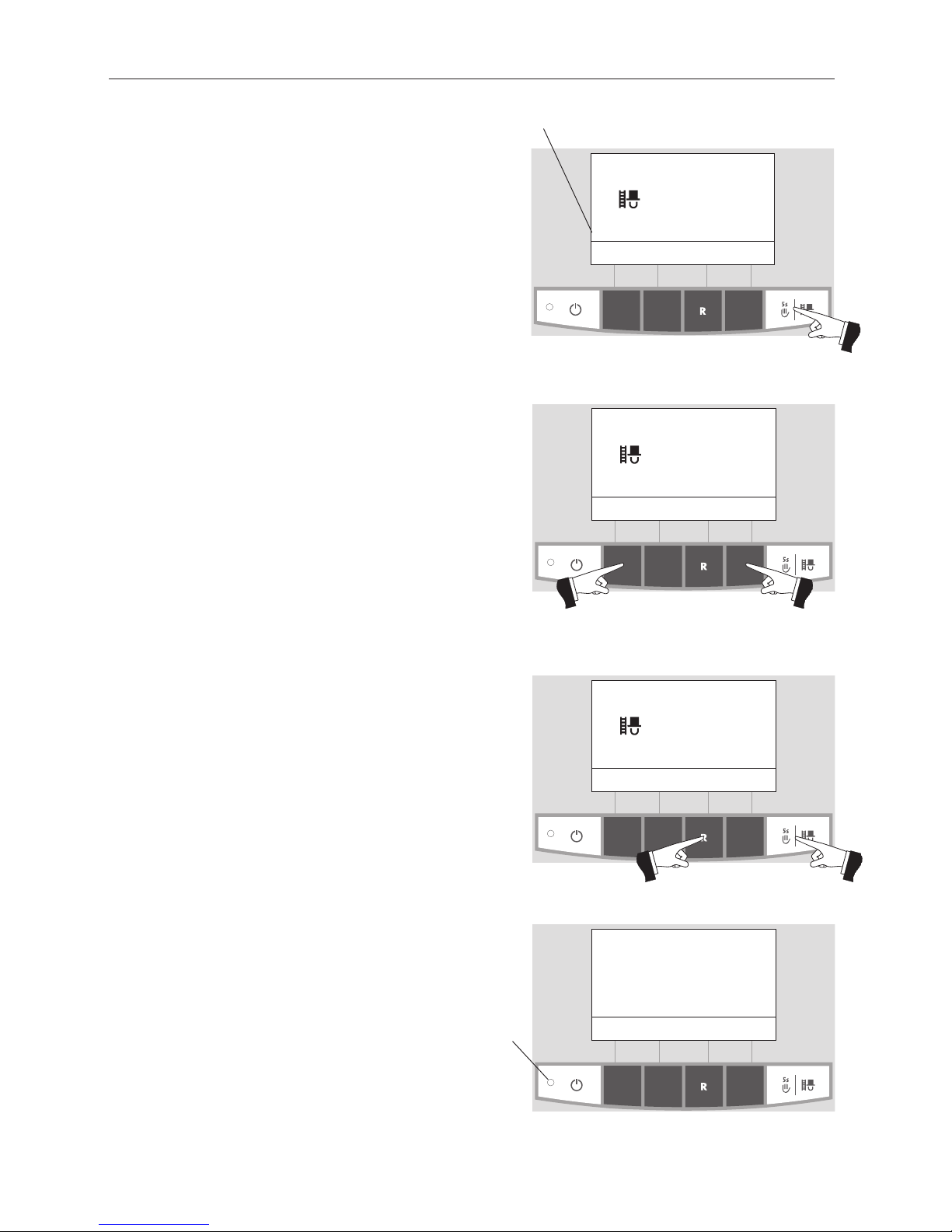
2.5.6 Chimney sweeper function
This function aids the performance of legally-required
emissions testing.
Note!
The chimney sweeper function cannot be started in “solid
fuel/buffer mode”. The chimney sweeper function must not be
started if an installed solid fuel boiler is operating (heated up).
The chimney sweeper function may be started if there is no
solid fuel boiler installed or if this is not operating but only the
accumulator tank is active. In this case, first set the operating
mode switch on the WVF+ to relay test 2 or on the B-PLM+ to
relay test 1 (see WVF+ or B-PLM+ operating manual).
A short press of the Manual operation / chimney sweeper
function button switches on the lighting and display. Pressing the button again starts the chimney sweeper function
– Fig. 21. The boiler temperature is set to approx. 60 °C for
45 min.
Fig. 21
Chimney sweeper func.
Power 100% 45 min
(Operating phases)
30% Cancel 100%
42
°C
(Symbol flashes)
The various operating phases are displayed here,
including Burner in operation, Burner OFF, etc.
Pressing the corresponding menu button enables the boiler to be operated with 30 % or 100 % output – Fig. 22. The
lighting is switched off after the lighting timer has counted
down (10 min.); the function or display remains unchanged.
Only the lighting is switched on when the button is first
pressed.
The operating time is reset to 45 min. when the Manual operation / chimney sweeper function button is pressed again.
Fig. 22
Chimney sweeper func.
Power 30% 45 min
(Operating phases)
30% Cancel 100%
42
°C
(Symbol flashes)
Fig. 23
Chimney sweeper func.
Power 30% 45 min
(Operating phases)
30% Cancel 100%
42
°C
(Symbol flashes)
Fig. 24
Shut-down procedure
Burnout
Info Menu
42
°C
The chimney sweeper function ends
– when the Cancel button is pressed – Fig. 23.
– automatically after about 45 minutes.
2.5.7 Shut-down procedure
The boiler is switched off - Fig 24.
The green LED flashes

18
2. Operation
2.6 Operating phases
2.6.1 Standby
During this operating phase, the controls do not transmit requests for heat. The
burner is switched off and the boiler temperature setpoint is 0 °C.
After an hour in standby mode, the display is shut down fully, only the green LED
is lit up. The display is switched back on by pressing a button or when there is
a heating requirement.
Fig. 25
Boiler temperature
Standby
Info Menu
42
°C
Fig. 26
Boiler temperature
Purging
Info Menu
42
°C
2.6.2 Purging
The Induced draught fan runs, the combustion chamber of the boiler is flushed
through with fresh air. This phase can last several minutes before the burner
fires.
2.6.3 Ignition phase
The Induced draught fan runs, pellets are transported into the burner pot and
are ignited. When flame formation is detected, the system switches over to flame stabilisation.
2.6.4 Flame stabilisation
Following the ignition procedure, even combustion is established and then the
system switches over to modulation mode.
2.6.5 Modulation mode
The burner is in modulation mode. The output is infinitely varied between 30 %
and 100 %.
2.6.6 Burnout
Combustion is stopped. Pellet transport into the burner pot is stopped, the Induced draught fan continues to run until all the remaining pellets have been
burned and the burner pot has cooled down.
2.6.7 Burner OFF
There is a heating requirement from the control system, but the boiler temperature (actual value) is higher than the boiler temperature setpoint. This means
combustion is stopped and the burner is switched off.
Fig. 27
Boiler temperature
Ignition phase
Info Menu
42
°C
Fig. 28
Boiler temperature
Flame stabilisation
Info Menu
42
°C
Fig. 29
Boiler temperature
Modulation mode
Info Menu
42
°C
Fig. 30
Boiler temperature
Burnout
Info Menu
42
°C
Fig. 31
Boiler temperature
Burner OFF
Info Menu
42
°C
 Loading...