

Page 1
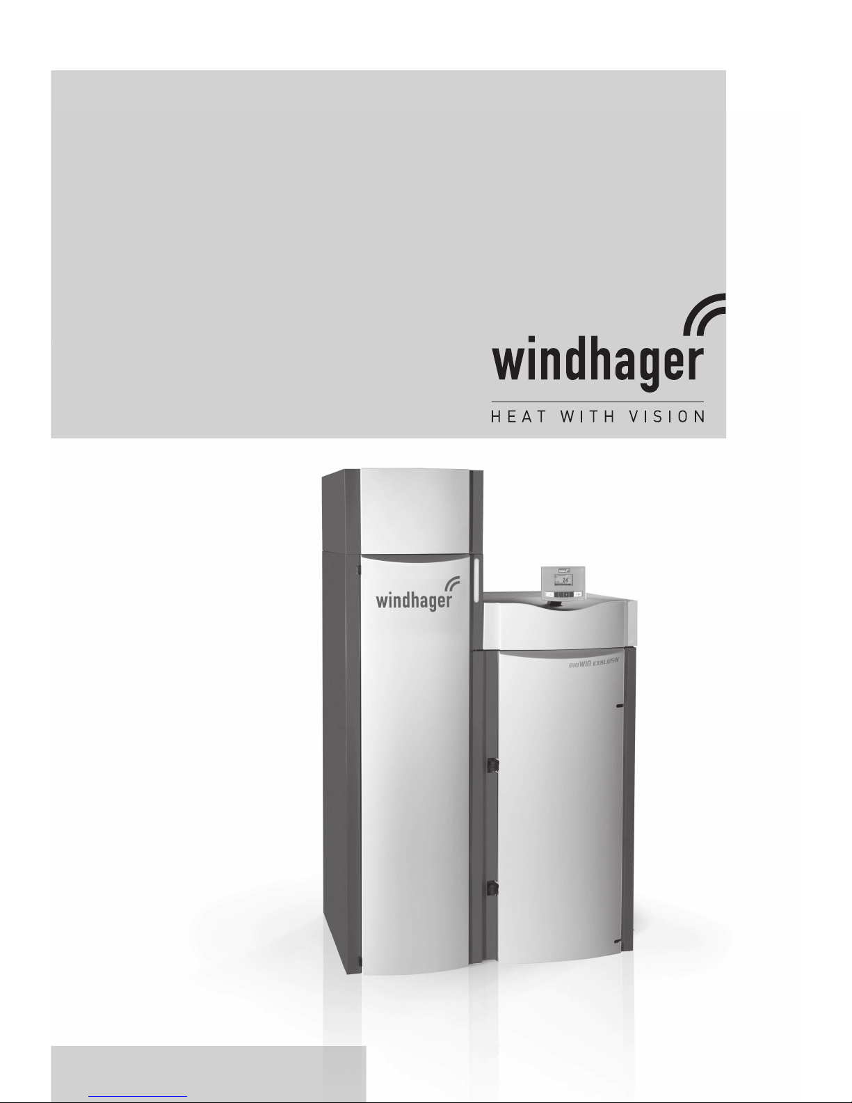
Assembly instructions
BioWIN
windhager.com
Pellet central heating boiler
Output range: 2,9 to 25,9 kW
Cascae options up to 78 kW
Pellets
03/2013 091698/09
Page 2

2
Table of contents
Table of contents
1. Important initial information for the Technician . . . . . . . . . . . . . . . . . . . . . . . . . . . . . . . . . . . 4
1.1 Safety precautions . . . . . . . . . . . . . . . . . . . . . . . . . . . . . . . . . . . . . . . . . . . . . . . . . . . . . . . . . . . . . . . . . . . . . .4
1.2 Flue . . . . . . . . . . . . . . . . . . . . . . . . . . . . . . . . . . . . . . . . . . . . . . . . . . . . . . . . . . . . . . . . . . . . . . . . . . . . . . . . . .4
1.3 Boiler room/Installation room . . . . . . . . . . . . . . . . . . . . . . . . . . . . . . . . . . . . . . . . . . . . . . . . . . . . . . . . . . . .5
1.4 Fuel storage . . . . . . . . . . . . . . . . . . . . . . . . . . . . . . . . . . . . . . . . . . . . . . . . . . . . . . . . . . . . . . . . . . . . . . . . . . .5
2. For the Installer . . . . . . . . . . . . . . . . . . . . . . . . . . . . . . . . . . . . . . . . . . . . . . . . . . . . . . . . . . . . . 7
2.1 Delivery, packaging . . . . . . . . . . . . . . . . . . . . . . . . . . . . . . . . . . . . . . . . . . . . . . . . . . . . . . . . . . . . . . . . . . . . .7
2.1.1 BioWIN Klassik . . . . . . . . . . . . . . . . . . . . . . . . . . . . . . . . . . . . . . . . . . . . . . . . . . . . . . . . . . . . . . . . . . . . . . . . . . . . . 7
2.1.2 BioWIN Premium and Exklusiv . . . . . . . . . . . . . . . . . . . . . . . . . . . . . . . . . . . . . . . . . . . . . . . . . . . . . . . . . . . . . . . . 7
2.1.3 Optional accessories . . . . . . . . . . . . . . . . . . . . . . . . . . . . . . . . . . . . . . . . . . . . . . . . . . . . . . . . . . . . . . . . . . . . . . . . 7
2.2 System . . . . . . . . . . . . . . . . . . . . . . . . . . . . . . . . . . . . . . . . . . . . . . . . . . . . . . . . . . . . . . . . . . . . . . . . . . . . . . . .8
2.2.1 Area of use . . . . . . . . . . . . . . . . . . . . . . . . . . . . . . . . . . . . . . . . . . . . . . . . . . . . . . . . . . . . . . . . . . . . . . . . . . . . . . . . 8
2.2.2 Standards . . . . . . . . . . . . . . . . . . . . . . . . . . . . . . . . . . . . . . . . . . . . . . . . . . . . . . . . . . . . . . . . . . . . . . . . . . . . . . . . . 8
2.2.3 Heating circuits . . . . . . . . . . . . . . . . . . . . . . . . . . . . . . . . . . . . . . . . . . . . . . . . . . . . . . . . . . . . . . . . . . . . . . . . . . . . . 8
2.2.4 Circulation pump . . . . . . . . . . . . . . . . . . . . . . . . . . . . . . . . . . . . . . . . . . . . . . . . . . . . . . . . . . . . . . . . . . . . . . . . . . . 8
2.2.5 Return temperature . . . . . . . . . . . . . . . . . . . . . . . . . . . . . . . . . . . . . . . . . . . . . . . . . . . . . . . . . . . . . . . . . . . . . . . . . 8
2.2.6 Accumulator tank . . . . . . . . . . . . . . . . . . . . . . . . . . . . . . . . . . . . . . . . . . . . . . . . . . . . . . . . . . . . . . . . . . . . . . . . . . . 8
2.2.7 Operating with external control . . . . . . . . . . . . . . . . . . . . . . . . . . . . . . . . . . . . . . . . . . . . . . . . . . . . . . . . . . . . . . . . 9
2.2.8 Heating water . . . . . . . . . . . . . . . . . . . . . . . . . . . . . . . . . . . . . . . . . . . . . . . . . . . . . . . . . . . . . . . . . . . . . . . . . . . . . . 9
2.2.9 Water-side resistance (pressure loss) . . . . . . . . . . . . . . . . . . . . . . . . . . . . . . . . . . . . . . . . . . . . . . . . . . . . . . . . . . 9
2.3 Combustion air . . . . . . . . . . . . . . . . . . . . . . . . . . . . . . . . . . . . . . . . . . . . . . . . . . . . . . . . . . . . . . . . . . . . . . . . 10
2.3.1 Operating with room air . . . . . . . . . . . . . . . . . . . . . . . . . . . . . . . . . . . . . . . . . . . . . . . . . . . . . . . . . . . . . . . . . . . . . 10
2.3.2 Operating independently of the room air . . . . . . . . . . . . . . . . . . . . . . . . . . . . . . . . . . . . . . . . . . . . . . . . . . . . . . . 10
2.4 Taking in . . . . . . . . . . . . . . . . . . . . . . . . . . . . . . . . . . . . . . . . . . . . . . . . . . . . . . . . . . . . . . . . . . . . . . . . . . . . . .10
2.4.1 Removing reserve supply container . . . . . . . . . . . . . . . . . . . . . . . . . . . . . . . . . . . . . . . . . . . . . . . . . . . . . . . . . . . 11
2.4.2 Removing the floor plate underneath the integral fuel hopper . . . . . . . . . . . . . . . . . . . . . . . . . . . . . . . . . . . . . . 13
2.4.3 Removing control panel . . . . . . . . . . . . . . . . . . . . . . . . . . . . . . . . . . . . . . . . . . . . . . . . . . . . . . . . . . . . . . . . . . . . . 13
2.5 Minimum clearances . . . . . . . . . . . . . . . . . . . . . . . . . . . . . . . . . . . . . . . . . . . . . . . . . . . . . . . . . . . . . . . . . . .15
2.6 Dimensional sketches . . . . . . . . . . . . . . . . . . . . . . . . . . . . . . . . . . . . . . . . . . . . . . . . . . . . . . . . . . . . . . . . . .16
2.7 Installation sequence . . . . . . . . . . . . . . . . . . . . . . . . . . . . . . . . . . . . . . . . . . . . . . . . . . . . . . . . . . . . . . . . . . . 16
2.8 Installing, preparing for installation. . . . . . . . . . . . . . . . . . . . . . . . . . . . . . . . . . . . . . . . . . . . . . . . . . . . . . .17
2.9 Fitting reserve supply container cover (only BioWIN Klassik) . . . . . . . . . . . . . . . . . . . . . . . . . . . . . . . . . .18
2.10 Fitting cleaning lever (only BioWIN Klassik and Premium) . . . . . . . . . . . . . . . . . . . . . . . . . . . . . . . . . . . . 18
2.11 Installing the exhaust pipe . . . . . . . . . . . . . . . . . . . . . . . . . . . . . . . . . . . . . . . . . . . . . . . . . . . . . . . . . . . . . .19
2.12 Fitting cleaning tools . . . . . . . . . . . . . . . . . . . . . . . . . . . . . . . . . . . . . . . . . . . . . . . . . . . . . . . . . . . . . . . . . . .19
2.13 Installing the thermal process safeguard . . . . . . . . . . . . . . . . . . . . . . . . . . . . . . . . . . . . . . . . . . . . . . . . . .19
2.14 Fitting feed unit on reserve supply container (only BioWIN Premium and Exklusiv) . . . . . . . . . . . . . . . 20
2.15 Initial start-up and operating instructions. . . . . . . . . . . . . . . . . . . . . . . . . . . . . . . . . . . . . . . . . . . . . . . . . .22
3. For the Electrician . . . . . . . . . . . . . . . . . . . . . . . . . . . . . . . . . . . . . . . . . . . . . . . . . . . . . . . . . . . 23
3.1 Electrical connections . . . . . . . . . . . . . . . . . . . . . . . . . . . . . . . . . . . . . . . . . . . . . . . . . . . . . . . . . . . . . . . . . .23
3.1.1 Electrical connection for control and changeover unit . . . . . . . . . . . . . . . . . . . . . . . . . . . . . . . . . . . . . . . . . . . . 24
3.1.2 Electrical connection for control and changeover unit . . . . . . . . . . . . . . . . . . . . . . . . . . . . . . . . . . . . . . . . . . . . 25
Page 3

3
Table of contents
4. For the Service Technician . . . . . . . . . . . . . . . . . . . . . . . . . . . . . . . . . . . . . . . . . . . . . . . . . . . . 26
4.1 Start-up and operating instructions . . . . . . . . . . . . . . . . . . . . . . . . . . . . . . . . . . . . . . . . . . . . . . . . . . . . . . .26
4.2 Service and repair work . . . . . . . . . . . . . . . . . . . . . . . . . . . . . . . . . . . . . . . . . . . . . . . . . . . . . . . . . . . . . . . . .26
4.3 Checking and servicing the thermal process safeguard . . . . . . . . . . . . . . . . . . . . . . . . . . . . . . . . . . . . . . 26
4.4 Technical data for calculating the flue gas system acc. to EN 13384-1 . . . . . . . . . . . . . . . . . . . . . . . . . . 27
4.5 Technical data – General . . . . . . . . . . . . . . . . . . . . . . . . . . . . . . . . . . . . . . . . . . . . . . . . . . . . . . . . . . . . . . . . 27
4.6 Service level . . . . . . . . . . . . . . . . . . . . . . . . . . . . . . . . . . . . . . . . . . . . . . . . . . . . . . . . . . . . . . . . . . . . . . . . . .28
4.6.1 Parameters . . . . . . . . . . . . . . . . . . . . . . . . . . . . . . . . . . . . . . . . . . . . . . . . . . . . . . . . . . . . . . . . . . . . . . . . . . . . . . . 30
4.6.2 Start-up . . . . . . . . . . . . . . . . . . . . . . . . . . . . . . . . . . . . . . . . . . . . . . . . . . . . . . . . . . . . . . . . . . . . . . . . . . . . . . . . . . 34
4.6.3 Actuator test . . . . . . . . . . . . . . . . . . . . . . . . . . . . . . . . . . . . . . . . . . . . . . . . . . . . . . . . . . . . . . . . . . . . . . . . . . . . . . 34
4.6.4 Settings . . . . . . . . . . . . . . . . . . . . . . . . . . . . . . . . . . . . . . . . . . . . . . . . . . . . . . . . . . . . . . . . . . . . . . . . . . . . . . . . . . 34
4.6.5 Installation of MESplus modules . . . . . . . . . . . . . . . . . . . . . . . . . . . . . . . . . . . . . . . . . . . . . . . . . . . . . . . . . . . . . . 35
4.7 InfoWINplus basic settings . . . . . . . . . . . . . . . . . . . . . . . . . . . . . . . . . . . . . . . . . . . . . . . . . . . . . . . . . . . . . .36
4.8 Basic BioWIN 100–260 circuitry . . . . . . . . . . . . . . . . . . . . . . . . . . . . . . . . . . . . . . . . . . . . . . . . . . . . . . . . . . 38
4.9 BioWIN 100–260 connecting diagram . . . . . . . . . . . . . . . . . . . . . . . . . . . . . . . . . . . . . . . . . . . . . . . . . . . . . .39
4.10 BioWIN 100-260 pellet feed connecting diagram with mixer for buried tank . . . . . . . . . . . . . . . . . . . . . 40
4.11 Circuit diagram for BioWIN 100–260 pellet feed with solo probe . . . . . . . . . . . . . . . . . . . . . . . . . . . . . . .41
4.12 Connecting diagram for air intake/exhaust flap . . . . . . . . . . . . . . . . . . . . . . . . . . . . . . . . . . . . . . . . . . . . .42
4.13 Connecting diagram for flue gas thermostat . . . . . . . . . . . . . . . . . . . . . . . . . . . . . . . . . . . . . . . . . . . . . . .43
Guarantee and warranty limitations . . . . . . . . . . . . . . . . . . . . . . . . . . . . . . . . . . . . . . . . . . . . . . 44
Page 4
4
1. Important initial information for the Technician
1. Important initial information for the Technician
1.1 Safety precautions
The boiler and related accessories are state of the art and meet all applicable safety regulations. Your boiler and
all accessories operate using 230 V AC electric current. Improper installation or repair can pose the danger of
life-threatening electric shock. Installation may be performed only by appropriately qualified technicians.
Caution symbols
Please take careful note of the following symbols in these Installation instructions.
Attention!
Ignoring the warnings identified can lead to personal injury.
Information!
Ignoring the warnings identified can lead to malfunction of, or damage to the boiler or heating system.
Note!
The blocks of text highlighted provide information and tips for operation.
1.2 Flue
A properly dimensioned flue is required for optimal functioning of the combustion system. Measurement of the
dimensions must follow EN 13384-1. See the Technical data section for values required for this calculation.
Please note that in the lower performance range, flue gases may be below 90°C. Therefore, thermally-insulated
flues meeting thermal transmittance coefficient Group I requirements according to DIN 18160 T1 or other appropriate, officially approved may be connected to the hearths.
The flue gas system must display at least the following classification:
Temperature class: T400 = nominal operating temperature 400 °C
Soot fire resistance class: G = flue gas system with soot fire resistance
Corrosion resistance class: 2 = suitable for unprocessed wood fuels
We would recommend fitting an energy-saving intake regulator for problem-free operation. This will largely
prevent moisture in the flue, and losses resulting from down-time will be reduced (draught interruptions). If you
have a feed pressure (flue draught) of more than 0.20 mbar, the energy-saving intake regulator must be fitted.
According to TRVB H118 a deflagration flap (combi energy-saving intake regulator with explosion flap EEX) must
be fitted in the connecting piece (exhaust pipe) or in the flue inside the boiler room.
Our recommendation: Fit the exhaust pipe upward to the flue with U-bolts and provide an opening for cleaning.
Insulate the exhaust pipe to avoid low flue intake temperatures.
Information!
Frequently, overhaul of existing systems involves oversized flue cross-sections or flues not designed for lowtemperature operation. We suggest an evaluation by the local building inspector before
installing the boiler system. In this way appropriate modifications can be made to the flue before
system installation (see technical data for flue calculation values).
Page 5
5
1. Important initial information for the Technician
1.3 Boiler room/Installation room
– The minimum clearances for connections, cleaning and maintenance must be complied with – see section 2.3
Minimum service clearances.
– Sufficient ventilation of the set-up area must be assured. See section 2.6 Combustion air.
– The boiler must be installed in dry premises!
– The boiler may not be installed in rooms that are very dusty or humid.
Permissible limit values: Air humidity: 85 % at room temperature of 25 °C (non-condensing)
Room temperature: +2 to +40 °C
Attention!
The configuration of the entire system must comply with the requirements of regional legislation,
applicable regulations, standards and guidelines.
1.4 Fuel storage
The pellets must be stored in a dry place in order to achieve trouble-free operation with optimum combustion
and at maximum efficiency. The pellets can be stored in bulk in a storage room, sheet steel tank, fabric tank or a
buried tank. The requirements for pellet storage are defined in ÖNORM M7137 for Austria or the Firing Ordinance
FeuV for Germany.
See the separate planning documents for planning information about pellet storage.
Maximum transport length or height for a pellet feed system:
These max. values require a stable power supply (min. 220 V under load!)
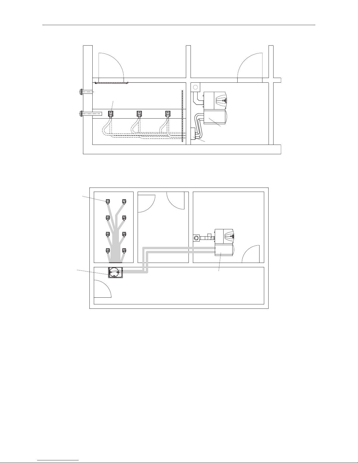
The BioWIN 100–260 can be operated with 2–3 probes (Fig. 2) or with up to 8 probes (Fig. 3).
Max. distance of 25 m between furthest away probe and pellet boiler with max. total height difference of 1.8 m
Max. distance of 15 m between furthest away probe and pellet boiler with max. total height difference of 2.8 m
Max. distance of 10 m between furthest away probe and pellet boiler with max. total height difference of 4.5 m
Total height difference: Sum of lengths of all rising pipes
Information!
The pellets must be transported carefully into and out of the storage room so as to maintain good pellet
quality.
Page 6
6
1. Important initial information for the Technician
Fig. 2 Storage room, Boiler room – view from above
Fig. 3 Storage room, Boiler room – view from above
Furthest away probe
changeover unit
Storage room
Suction turbine
BioWIN 100–260
Boiler room
Furthest away probe
changeover unit
Storage room
Suction turbine
BioWIN 100–260 Boiler room
BioWIN 100–260 (3 probe):
BioWIN 100–260 (8 probe):
Page 7

7
2. For the Installer
2. For the Installer
2.1 Delivery, packaging
2.1.1 BioWIN Klassik
Boiler fully fitted, insulated and encased in stable crate with boiler control panel.
Cleaning tools packed in combustion chamber. Reserve supply container cover packed in a cardboard box.
2.1.2 BioWIN Premium and Exklusiv
Boiler fully fitted, insulated and encased in stable crate with boiler control panel.
Cleaning tools packed in combustion chamber. In addition, the feed unit (fully automated pellet feed) is packed in
a cardboard box.
2.1.3 Optional accessories
Accessories for boiler
MESplus-System control, 3/4” or 1” motorised mixing valve, mixer groups, heating distributor, thermal process
safeguard – FK-060 (for BioWIN 210/260 only), stainless steel flue accessory, combi energy-saving intake regulator with explosion flap EEX (EZR for Germany), cleaning kit – FAX 090 (incl. vacuum cleaner)
Accessories for fully-automatic pellet feed
– Fully automated changeover unit with/without fire protection collars including 3x suction probes
– Fully automated changeover unit with/without fire protection unit including 8x suction probes and masonry
feed-through
– Fastening clips for delivery hose (pack of 6)
– Delivery hose with flexible earth leads, DN 50/25 m (supply and return air hoses)
– Connecting piece for return air hose
Accessories for storage room
– Filling coupling set NW 100 mm (2 Storz A couplings with 0.5 m pipe, incl. fastening material ) – with blockable
blind covers
– Z-brackets (2 of 2 m each) incl. bolts and dowels for storage room door
– Baffle plate made from plastic (1500 x 1500 x 2 mm) incl. fastening material for storage room
– Fire protection collars (2 pieces) incl. masonry attachment
– Pipe clamp for earthing the filling and return air lines Ø 100 mm and attaching them to the wall
– Pipes and bends (natural aluminium) for extending the filling and return air pipes Ø 100 mm
Pellet storage rooms
– Sheet steel tank with volume of 2.3 to 9.6 t
– Fabric tank with volume of 2.1 to 6.1 t
Page 8

8
2. For the Installer
2.2 System
2.2.1 Area of use
For heating buildings acc. to EN 12831.
The boilers are designed and approved as heat generators for hot water heating systems with a permissible flow
temperatures of up to 90°C. They may be installed only in sealed systems. The maximum flow temperature is
factory-set at 75°C.
2.2.2 Standards
The following European standard should be followed: EN 12828, this specifies that the following should be fitted:
a) A closed expansion tank.
b) A reliably functioning safety valve installed at the highest point of the boiler or at a non-closable line.
c) A thermometer, a pressure gauge.
d) A low-water cut-off: A low-water cut-off is not required for systems providing up to 300 kW nominal thermal
output, if it can be assured that excess heating will not result from a lack of water in the system.
If the boiler is above the radiators, then a low-water cut-off must be installed.
e) Only relates to boiler models with a thermal safety device:
An automatic device for dissipating heat which will prevent the maximum permitted operating temperature
from being exceeded. The built-in thermal safety device (not present with all boiler models) should always be
used with the thermal process safeguard.
2.2.3 Heating circuits
A motorised mixing valve is always required for the BioWIN in order to protect the boiler and one must be fitted in
each heating circuit. A feed contact thermostat (FK-001) must be installed for underfloor circuits.
2.2.4 Circulation pump
We recommend using pumps efficiency class A
2.2.5 Return temperature
The return flow temperature increase installed as standard means that BioWIN can be operated with a return
temperature down to min. 20 °C. No external return flow temperature increase is required.
Exception: Systems with a buffer in which the buffer is loaded directly from BioWIN with a return hold-up group.
2.2.6 Accumulator tank
In principle a pellet boiler system does not need an accumulator tank. A guaranteed minimum heat consumption
is required, e.g. fit a consumer circuit that cannot be blocked off or do not fit thermostat valves on all radiators.
The BioWIN 100–260 needs a buffer if:
– the total heating requirements of the building according to the ÖNORM M 7500 or EN 12831 calculation are less
than 50 % of the boiler‘s nominal output.
Information!
If using a buffer, the BioWIN return flow temperature must be increased – see hydraulic diagram in
the planning documents.
Page 9

9
2. For the Installer
2.2.7 Operating with external control
The following requirements must be satisfied for this interface:
– Minimum boiler temperature and start-up relief:
The consumer pumps (heating circuit and domestic water pumps) may only be switched on at a boiler tem-
perature of more than 50 °C if the burner is on and must be switched off at a boiler temperature of less than
45°C.
– Pump lag time:
A lag time of at least 10 min. must be observed for all consumer pumps and a minimum heat consumption
must be ensured during the burnout phase.
a) Heating requirement (setpoint specification) with 2-point controller
The 2-point controller switches the burner ON/OFF with a potential-free contact via the “external heating re-
quirement” interface of the BioWIN.
b) Heating requirement (setpoint specification) with analogue interface
The controller passes the external boiler temperature setpoint via the analogue 0–10 V interface.
2.2.8 Heating water
a) The chemical composition of the heating water must meet the specifications of ÖNORM H 5195 Part 1 or VDI
2035 P1. According to ÖNORM M 5195 Part 1 (2010 edition), the condition of the heating water must be checked
every 2 years by a heating technician in order to avoid corrosion and sediment accumulation in the heating
system.
b) The pipe lines and heating appliances should be thoroughly rinsed before the boiler is connected.
c) To protect the boiler from contamination from the heating system, installation of a dirt trap is required in old
or existing systems (mesh size 0.5 mm) with maintenance cocks installed in the return line.
d) If oxygen diffusion or sludge build-up cannot be prevented, the system must be segregated by means of a heat
exchanger.
e) If antifreeze is used, a minimum volume of 20 % antifreeze is required, otherwise corrosion prevention is not
guaranteed.
2.2.9 Water-side resistance (pressure loss)
Diagramm 1 Water-side resistance - BW 100–260
BW 100–260
Pressure loss (mbar)
Flow rate (m
3
/h)
Page 10
10
2. For the Installer
2.4 Taking in
Information!
The appliance must be taken into the building and installed without subjecting it to significant knocks
and jolts. All warranty claims will be invalidated if the appliance is damaged due to having been taken
into the building and installed incorrectly or if the appliance malfunctions as a consequence of this.
There are several possible forms of delivery for the BioWIN. The boiler is best moved to the installation site in a
crate (790 mm wide). In order to bring in the boiler more easily and most importantly more safely in tight situations, several add-ons can be removed so that the BioWIN is smaller and lighter.
Note!
The dimensioned parts are the rough key measurements. Small components (e.g. exhaust pipe, door
mounting etc. ) are outside the dimensioned area.
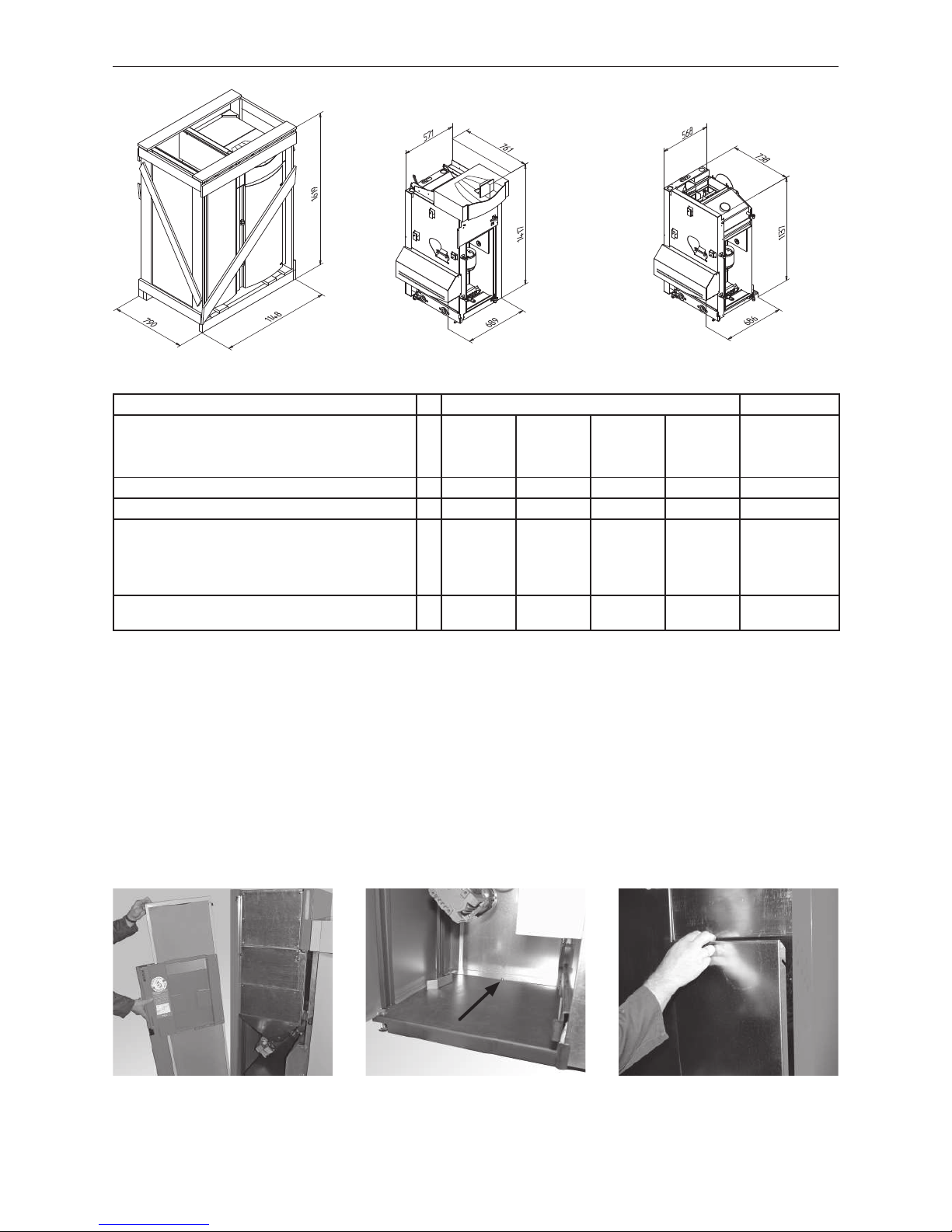
The four most effective installation dimensions or installation weights are:
a) Move BioWIN to installation site with crate – Fig. 4.
b) BioWIN without crate, reserve supply container, left-hand side wall, rear wall, cladding door on left, combusti-
on chamber door, ash container or ash - pan, blower box, blower unit, floor plate underneath the integral fuel
hopper – Fig.5.
c) in addition to point b) also without control panel and right side panel – Fig. 6.
2.3 Combustion air
An adequate supply of combustion air is absolutely essential. The combustion air must be free from pollutants
(gases, vapours and dusts), otherwise malfunctions and increased wear (e.g. corrosion) may occur.
2.3.1 Operating with room air
Combustion air supply directly from the installation room
The combustion air is drawn directly by the device from the installation room, therefore the installation room has
to be adequately ventilated. The combustion air should be fed to near the boiler.
The area of the free minimum cross-section must be 2.5 cm2 per kW of the boiler‘s nominal total output1.
The opening to the outdoors for combustion air should be designed as follows:
– the flow of air must not be restricted in any way by the weather (e.g. snow, leaves),
– the free cross-section area remains the same when taking the cover grille, discs etc. into consideration.
1
The boiler‘s nominal total output is the sum of the nominal outputs of all heat generators installed in the same boiler / installation room.
Information!
Malfunctions or complaints occasioned by inadequate combustion air will not be covered by the guarantee!
2.3.2 Operating independently of the room air
see separate technical sheet „Operating independently of the room air“.
Page 11
11
2. For the Installer
Boiler weights after removing add-ons:
BioWIN
Premium,
Klassik
BioWIN
Premium,
Klassik
BioWIN
Exklusiv
BioWIN
Exklusiv
Assembly and
disassembly
times for expe-
rienced fitters
BW 100/150 BW 210/260 BW 100/150 BW 210/260
a) BioWIN incl. crate kg 352 363 367 378 –
b) BioWIN without: crate, reserve supply container,
cladding door on left, left-hand side wall, rear wall,
ash container or ash pan, combustion chamber
door, blower unit, blower box, floor plate underneath the integral fuel hopper
kg 215,5 226,5 224,5 235,5
approx. 1.5
hours
c) BioWIN as above, also without control panel and
right-hand side wall
kg 192 202 200 211
approx. 2.5
hours
Fig. 4 BioWIN 100–260 in crate Fig. 5 BioWIN 100–260 without crate, clad-
ding and reserve supply container
Fig. 6 BioWIN 100–260 without control
panel
2.4.1 Removing reserve supply container
Order for disassembly:
– Remove wood partitions with the exception of the base pallet – see section 2.8.
– Unhook cladding door on left (Fig. 7) and remove ash container (BioWIN Exklusiv only).
– Remove reserve supply container rear wall cladding; remove 1 screw in the inside of the device under the re-
serve supply container next to the rear panel cladding (Fig. 8) and remove rear panel upwards – Fig. 9.
Fig. 7 Unhinging cladding door Fig. 8 Removing 1 screw Fig. 9 Unhinging rear panel
Page 12
12
2. For the Installer
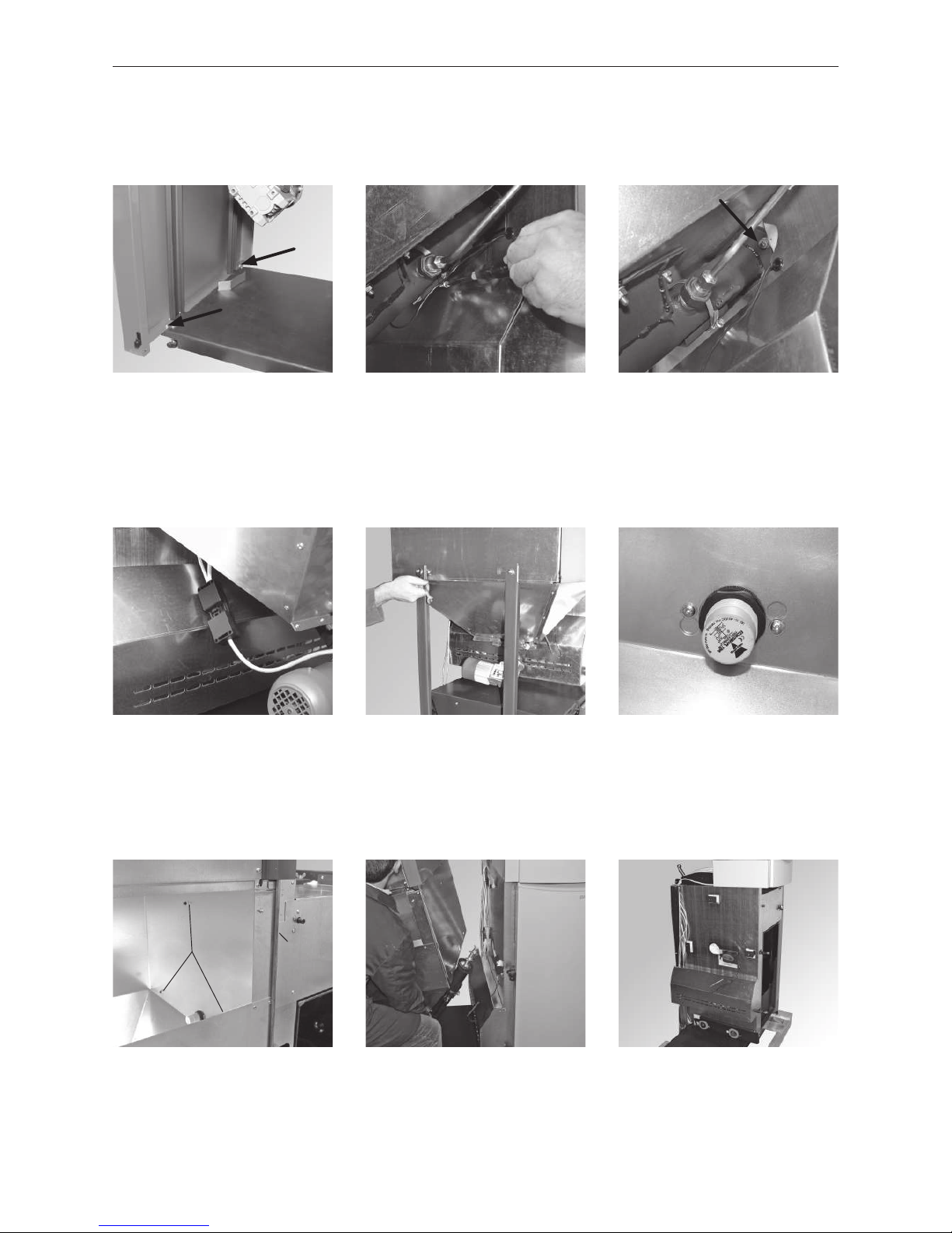
– Unscrew 3 nuts and 1 bolt on the outside side of the reserve supply container (Fig. 16), remove the reserve
supply container (carefully thread out downwards at the auger) – Fig. 17.
– Unhook combustion chamber door and remove ash pan (BioWIN Klassik and Premium only) – Fig. 18.
Fig. 16 Unscrewing nuts (3x) and bolt (1x) Fig. 17 Taking off reserve supply container Fig. 18 Removing combustion chamber
door and ash pan
Nuts Bolt
– Remove reserve supply container side wall; remove 2 screws in inside of the device under the reserve supply
container next to the side panel (Fig. 10) and remove the side panel.
– Remove sensor from safety thermostat auger tube; loosen sensor guard (Fig. 11) and take out sensor.
– Unscrew both nuts from the side of the auger tube flange
Fig. 10 Removing screws from inside
next to side panel
Fig. 11 Loosening sensor guard Fig. 12 Unscrewing nuts (2 items)
– Disconnect plug from auger motor – Fig. 13.
– Remove reserve supply container support feet: unscrew 4 nuts – Fig. 14.
– Loosen proximity switch in reserve supply container, loosen screws one turn, turn flange with proximity switch
anti-clockwise and press outwards – Fig. 15.
Fig. 13 Disconnecting auger motor plug Fig. 14 Removing support feet Fig. 15 Loosening proximity switch
– Removing blower wheel and blower box (see BioWIN Operating Manual, cleaning blower wheel, blower box)
Page 13
13
2. For the Installer
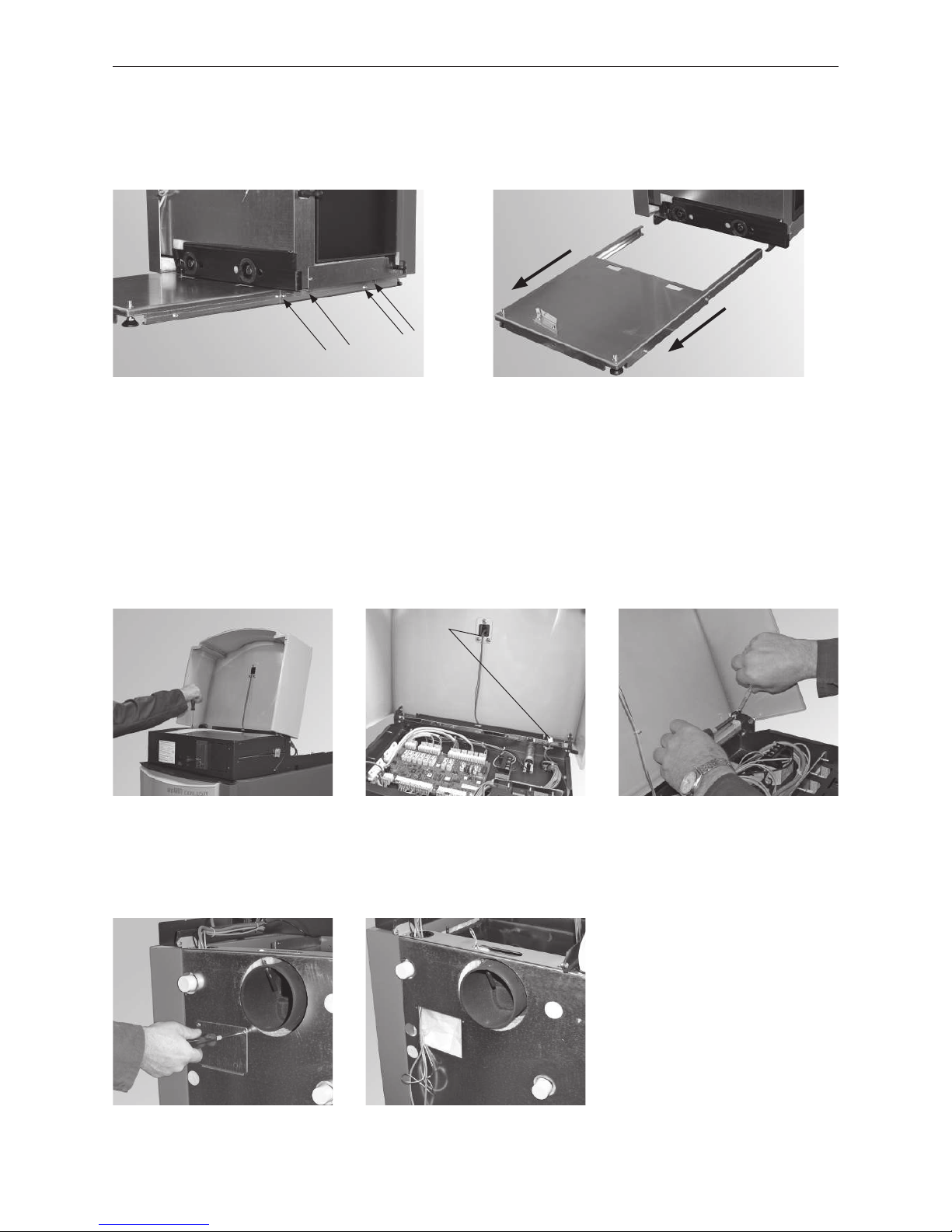
2.4.2 Removing the floor plate underneath the integral fuel hopper
– remove the 4 screws at the front and the 4 screws at the back of the base – Fig. 19.
– pull out and remove the floor plate – Fig. 20.
Fig. 19 Remove the screws Fig. 20 Pull out and remove the floor plate
2.4.3 Removing control panel
– Fold up cladding cover. Loosen the 2 screws on the side of the control panel cover (Fig. 21) and lift the cover up
and off.
– Disconnect cable(s) from InfoWINplus on firing PCB and remove strain relief (cable ties) – Fig.22.
– Remove cladding cover control panel; remove 2 bolts with nuts (Fig. 23) and take off cover.
Fig. 21 Loosening 2 bolts, removing
control panel cover
Fig. 22 Disconnecting cable(s) from
InfoWINplus
Fig. 23 Unscrewing cladding cover
Cable(s)
– Remove boiler sensor, safety thermostat sensor and exhaust gas sensor, unscrew cover on rear wall (Fig. 24).
Pull boiler and safety thermostat sensor out of immersion sleeve, pull exhaust gas sensor out of protective
tube in flue outlet (Fig. 25). Guide all 3 sensors out of the cable duct.
Fig. 24 Removing cover Fig. 25 Pulling out sensor
Page 14
14
2. For the Installer
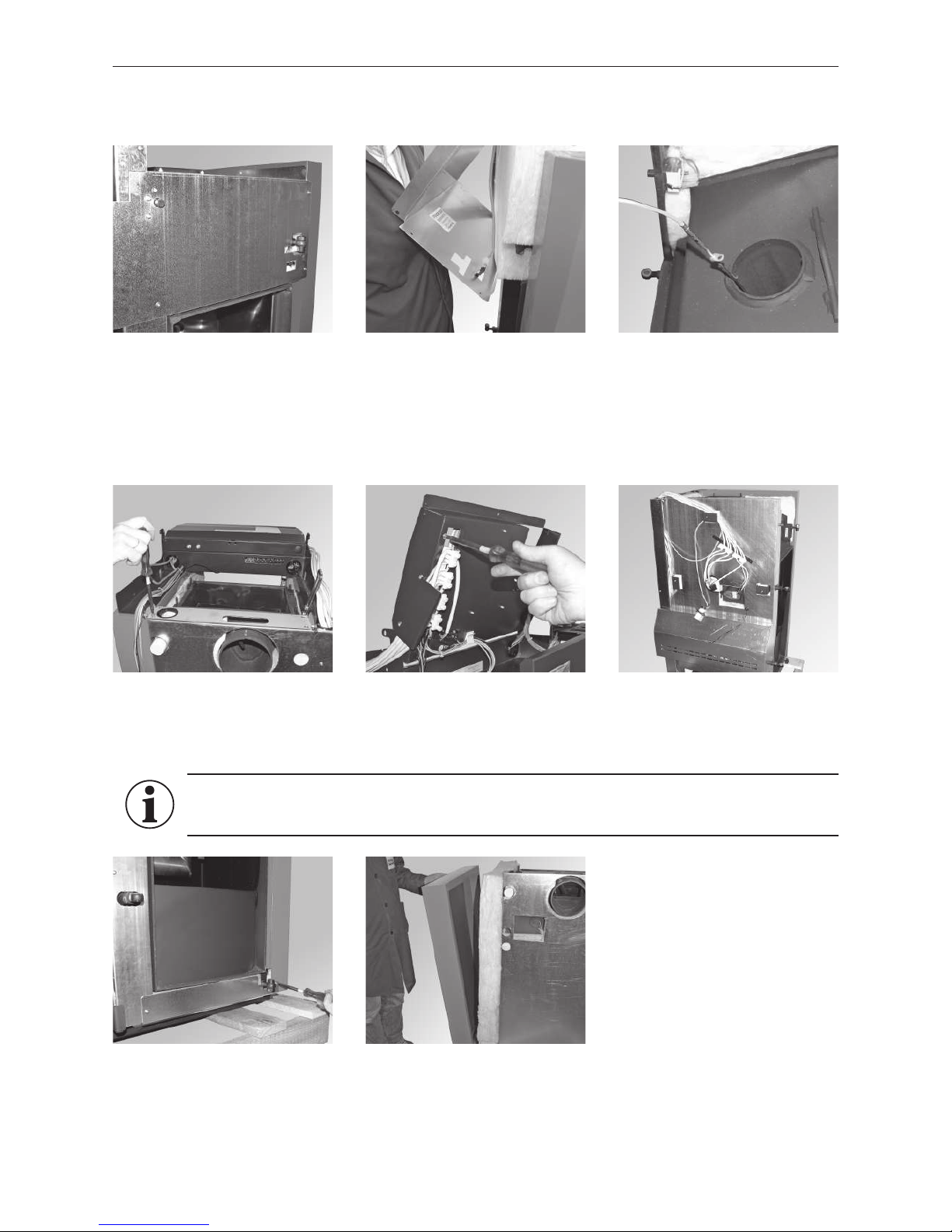
– Unscrew cover at top; remove screws (Fig. 26). Carefully lift cover out, pull cable off door safety switch – Fig. 27.
– Take off insulation at front and remove thermocontrol sensor – Fig. 28.
Fig. 26 Unscrewing cover at front Fig. 27 Disconnecting door safety switch Fig. 28 Removing thermocontrol sensor
– Remove 4 rear screws from control panel with retaining bracket – Fig. 29
– Disconnect all cables from cable harness and unscrew complete cable harness with strain relief (pinch off
cable ties) – Fig. 30.
– Take off control panel – Fig. 31.
Fig. 29 Removing retaining bracket Fig. 30 Unscrewing strain relief Fig. 31 Control panel removed
– Remove cladding bracket (2 screws) bottom front – Fig. 32.
– Unhook and remove right side panel at bottom – Fig. 33.
Fig. 32 Unscrewing connection bracket Fig. 33 Unhinging right side wall
Assembly:
After transporting into the boiler room, refit BioWIN in reverse order.
Information!
Do not remove insulation from side wall. The heating surface cleaning rod uses this insulation.
Page 15
15
2. For the Installer
2.5 Minimum clearances
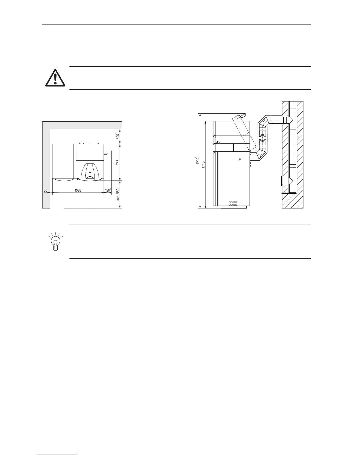
For maintenance and servicing it is essential to comply with the minimum clearances for the walls, hydraulic
components and connection pipes.
Fig. 34 BioWIN – view from above Fig. 35 Folding up control panel for cleaning
3
The minimum distance can be reduced by up to max. 50 mm.
4
If the room height is lower than 1900 mm, the switchboard cannot be locked anymore when lifted up (bracing has to be done on site). Also maintenance costs
can increase by a lower room height
Attention!
Follow the installation guidelines for boiler rooms!
Note!
The control panel must be folded all the way up for cleaning work – Fig. 35. Therefore, do not route the
exhaust pipe and connection pipes or position any hydraulic components directly behind the control panel.
A minimum distance of 500 mm should be observed on one side. Failure to do so will result in longer repairs.
All dimensions in mm:
Page 16
16
2. For the Installer
2.6 Dimensional sketches
All dimensions in mm:
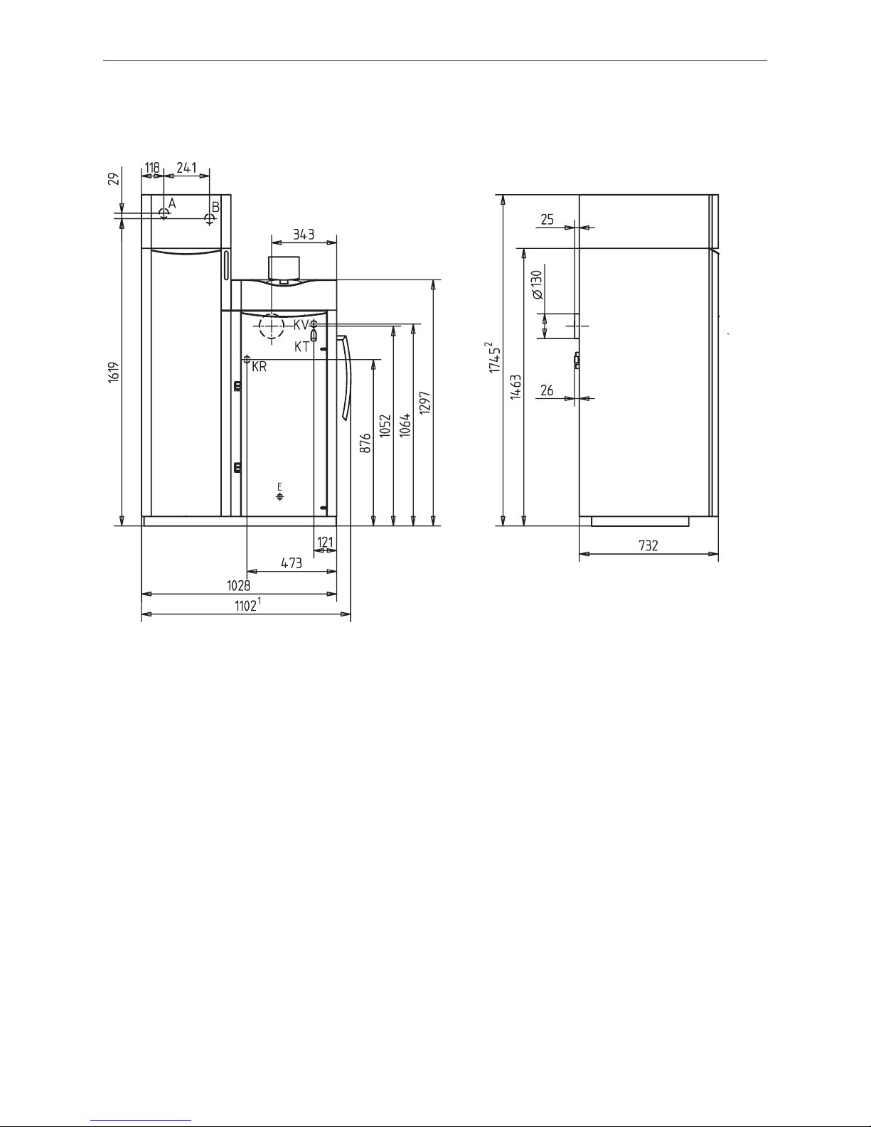
Fig. 36 BioWIN pellet boiler 100–260 – Front view
KV ........Boiler feed (1” tube)
KR ........Boiler return (1” tube)
E ..........Discharge
A ..........Pellet feed (50 mm Ø pipe)
B .......... Reverse air flow (50 mm Ø pipe)
KT ........Boiler temperature sensor
Z ..........Intake air for operating independently of the room air
1
Premium/Klassik types only
2
Exklusiv/Premium types only
Fig. 37 BioWIN pellet boiler 100–260 – Side view
2.7 Installation sequence
a) Transport boiler to installation site and remove crate see – section 2.8.
b) Fit reserve supply container cover (BioWIN Klassik only) – see section 2.9.
c) Fit cleaning lever (BioWIN Klassik and Premium only) – see section 2.10.
d) Install the exhaust pipe – see 2.11.
e) Fit cleaning tools – see section 2.12.
f) Fit feed unit on reserve supply container (BioWIN Premium and Exklusiv only) – see section 2.13.
g) Initial start-up and operating instructions – see section 2.14.
Page 17
17
2. For the Installer
2.8 Installing, preparing for installation
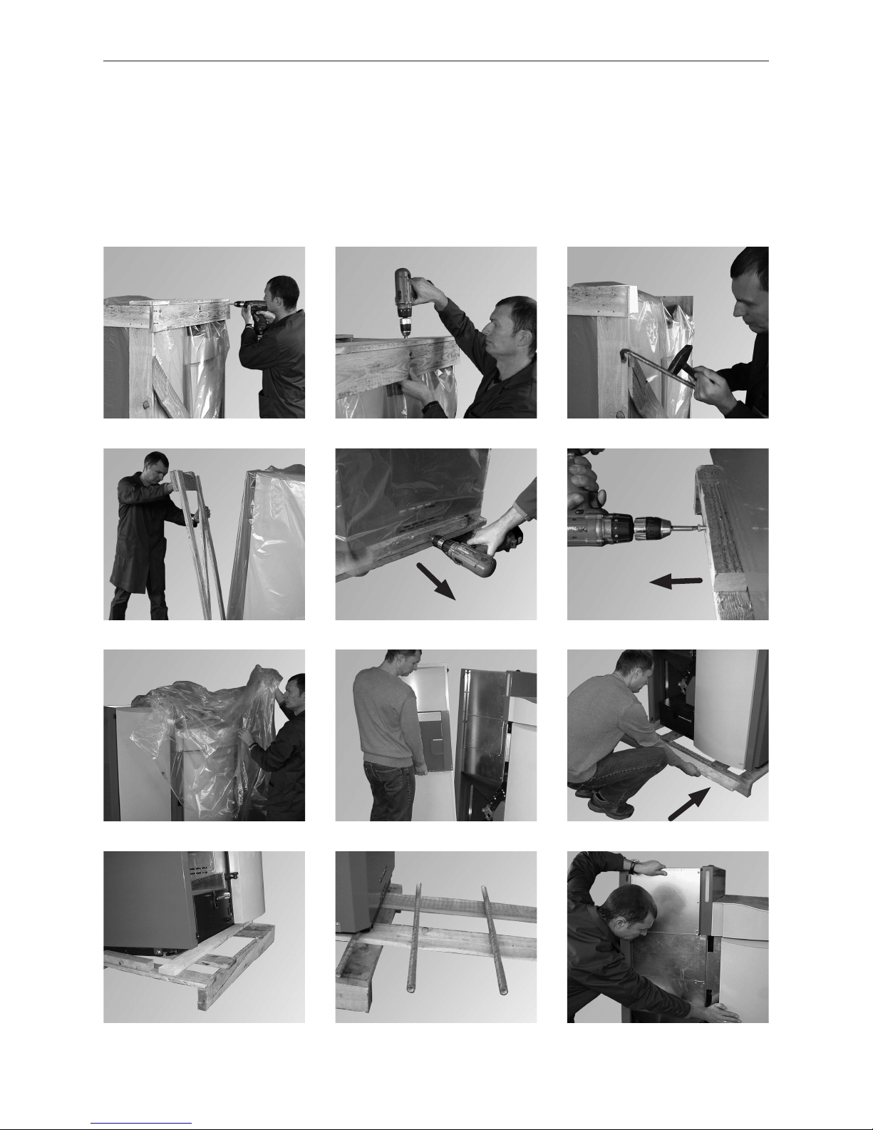
– The boiler is best transported to the installation site in the crate and this removed once there – Figs. 38 to 49. If
the boiler cannot be taken to the installation site in the crate, remove the crate and various attachments – see
section 2.4.
– The boiler can be installed directly on a non-flammable surface and does not require special foundations.
Using the four set screws, position horizontally or slightly inclined toward the rear.
Removing the crate
Fig. 38 Fig. 39 Fig. 40
Fig. 41 Fig. 42 Fig. 43
Fig. 44 Fig. 45 Fig. 46
Fig. 47 Fig. 48 Fig. 49
Page 18
18
2. For the Installer
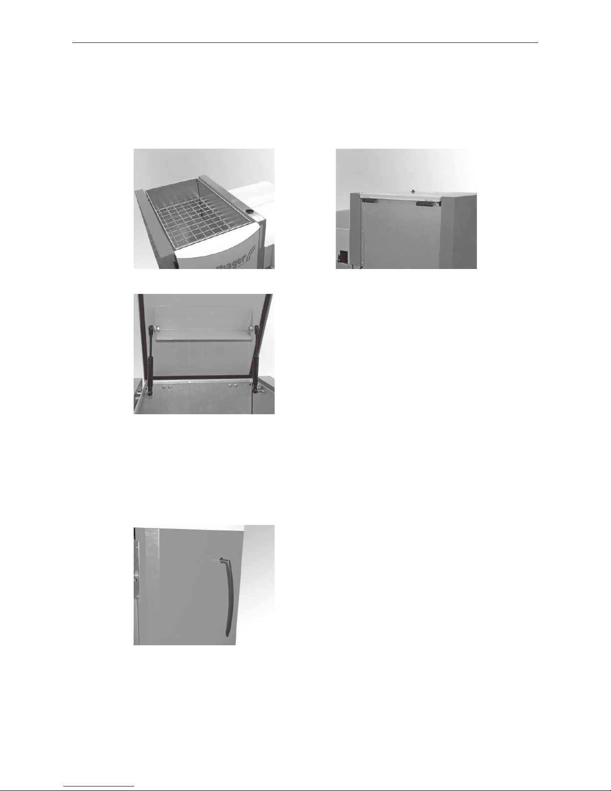
2.9 Fitting reserve supply container cover (only BioWIN Klassik)
– Insert protective grille in reserve supply container – Fig. 50.
– Fit both belts (bearings) with pre-fitted cover on reserve supply container (remove plug beforehand) – Fig. 51.
– Fit gas springs on reserve supply container – Fig. 52.
Fig. 50 Inserting protective grille Fig. 51 Fitting belts (bearings)
Fig. 52 Screwing on gas springs
2.10 Fitting cleaning lever (only BioWIN Klassik and Premium)
Punch through cut-out in right-hand side wall for cleaning lever and attach cleaning lever for heating surface
cleaning on side for BioWIN Premium/Klassik – Fig. 53.
Fig. 53 BioWIN Premium/Klassik - view from right
Page 19
19
2. For the Installer
2.11 Installing the exhaust pipe
Comply with minimum clearances in section 2.5!
a) Install the exhaust pipe upward to the flue (45° is the ideal angle). Maximum exhaust pipe length 3 m.
Information!
Any section of this exhaust line that only rises slightly (up to 30°) or is horizontal is not allowed to be
more than 1 m in length.
b) Avoid 90° bends, 45° bends are better
c) Make the flue connection at 45° if possible.
d) Do not push the exhaust pipe too far into the flue.
e) Do not seal the exhaust pipe completely into the flue. Connection with flexible exhaust pipe inlet into the flue.
The Induced draught fan can cause sound transmissions that create noise pollution.
f) The BioWIN is a low-pressure boiler and this means that the flue gas system needs to meet the „N1“ seal in-
tegrity requirement according to EN 1856-1 and EN1856-2. Please ensure a sufficient immersion depth when
fitting (e.g. when using Windhager stainless steel flue systems).
g) The entire exhaust line (particularly after 1 m length) should be insulated in order to prevent or minimise
condensation.
2.12 Fitting cleaning tools
1 ...........Cleaning brush
2 ...........Spatula
3 ...........Cleaning tool/cone removal tool
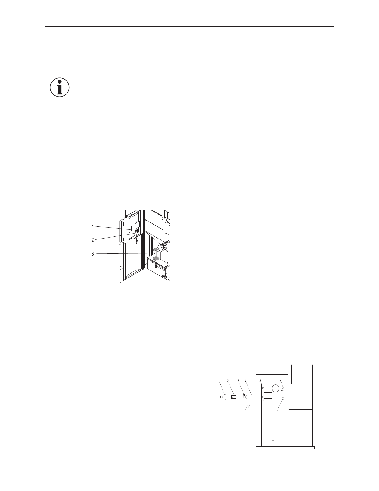
Fig. 54 BioWIN cleaning instruments
2.13 Installing the thermal process safeguard
(Not needed for all boiler models, only if the boiler has a thermal safety device.)
Connecting thermal process safeguard to thermal safety device
a) The thermal process safeguard and cleaning T-piece must still be accessible after installation.
b) Water must be seen to be draining out in order to check the function, therefore use a discharge funnel.
c) It must not be possible to block the connection manually.
Connection according to EN 303-5:
Fig. 55 Thermal safety device connection
Minimum connection pressure of the thermal safety device: 2 bar.
1 ...........Pressure reducing valve (only with CW connection of more than 6 bar)
2 ...........Dirt trap
3 ...........Thermal process safeguard (opens at approx. 95 °C)
4 ...........Cleaning T-piece
5 ...........Discharge funnel
6 ...........Immersion sleeve for the sensor of the thermal process safeguard
7 ...........Boiler return
8 ...........Boiler feed
Page 20
20
2. For the Installer
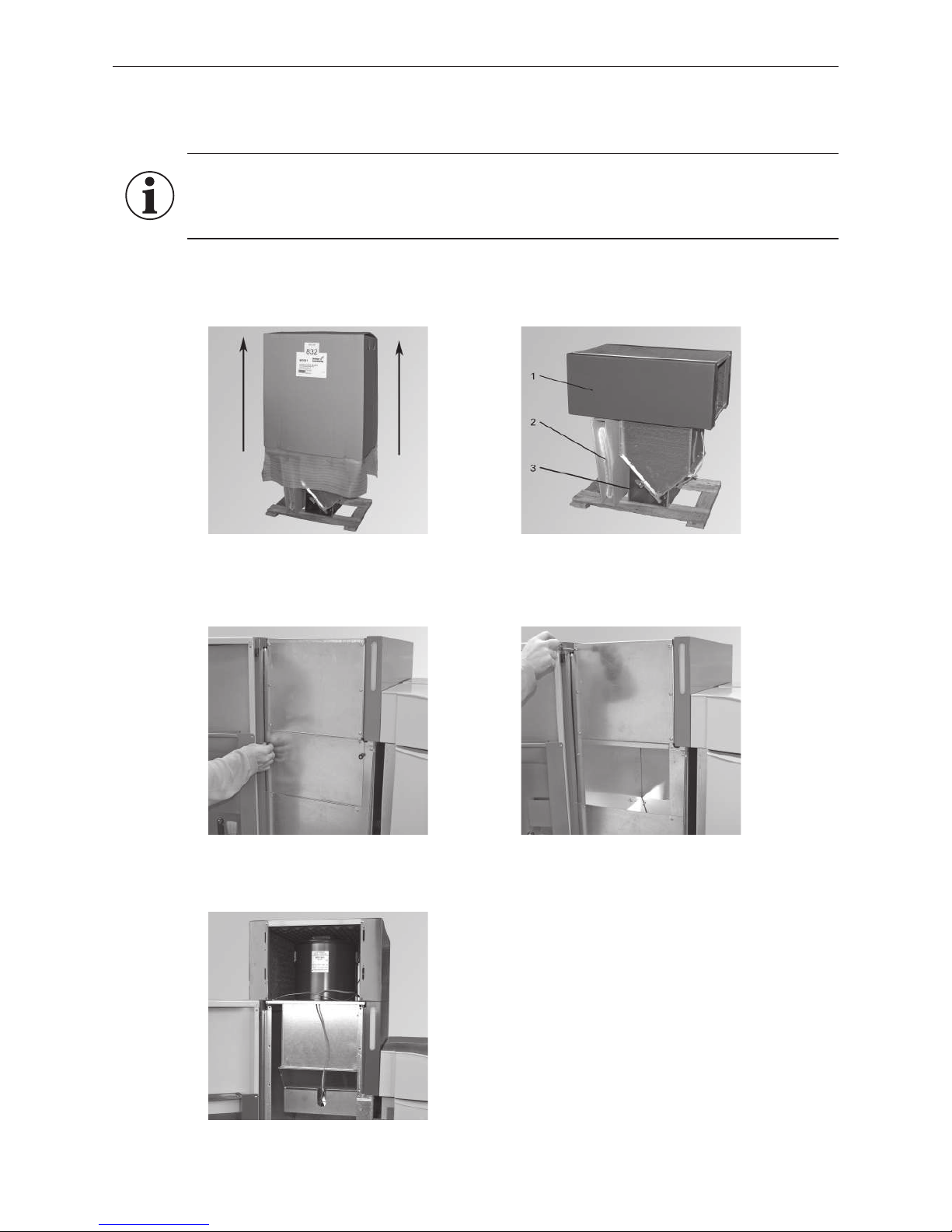
2.14 Fitting feed unit on reserve supply container
(only BioWIN Premium and Exklusiv)
Information!
Leave feed unit in cardboard box until it is fitted on the BioWIN reserve supply container. Only un-
screw transport protection after assembly on the reserve supply container – Fig. 57. The bottom flap
in the feed unit must not be damaged. 2 people are needed for assembly.
Fig. 56 Sliding cardboard box upwards Fig. 57 Feed unit without cardboard box
– Cut open tensioning belts
– Lift cardboard box up and off – Fig. 56.
1 ...........Feed unit with suction turbine
2 ...........Front cover
3 ...........Transport protection
– Open left cladding doors on BioWIN. Unscrew bottom inspection cover (2 knurled screws) and top inspection
cover (6 screws) – Fig. 58, 59.
Fig. 58 Unscrewing bottom inspection cover Fig. 59 Unscrewing top inspection cover
– Lift feed unit onto BioWIN reserve supply container – Fig. 60.
Fig. 60 Lifting feed unit onto reserve supply container
Page 21
21
2. For the Installer
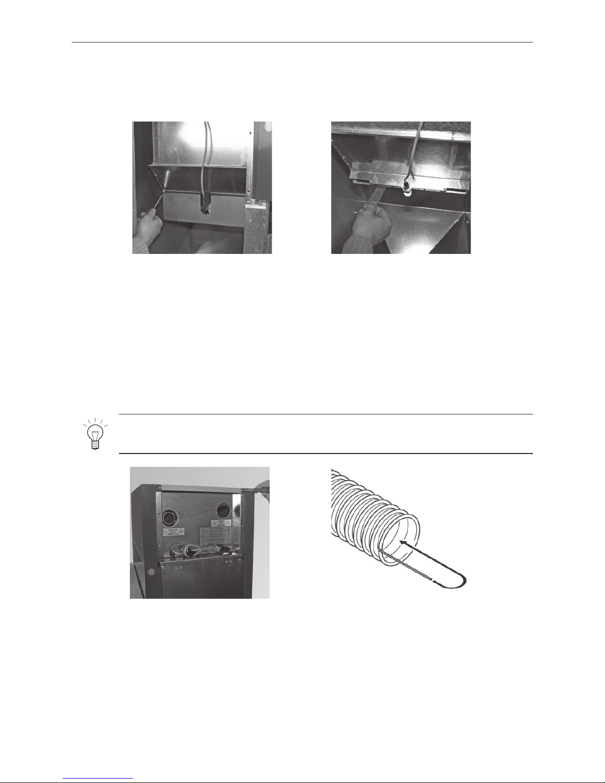
Note!
If you have problems connecting, dampen connections with water (do not use grease).
Fig. 61 Removing transport protection Fig. 62 Remove adhesive strip from flap
Fig. 63 Removing screws from top cover (4 x) Fig. 64 Exposing flexible earth leads,
Bending in flexible earth leads
– Remove transport protection, to do this loosen 2 screws at front and remove transport protection forwards –
Fig. 61.
– Remove adhesive protection strip from flap, flap must be able to move easily – Fig. 62.
– Refit both inspection covers - Fig. 58, 59.
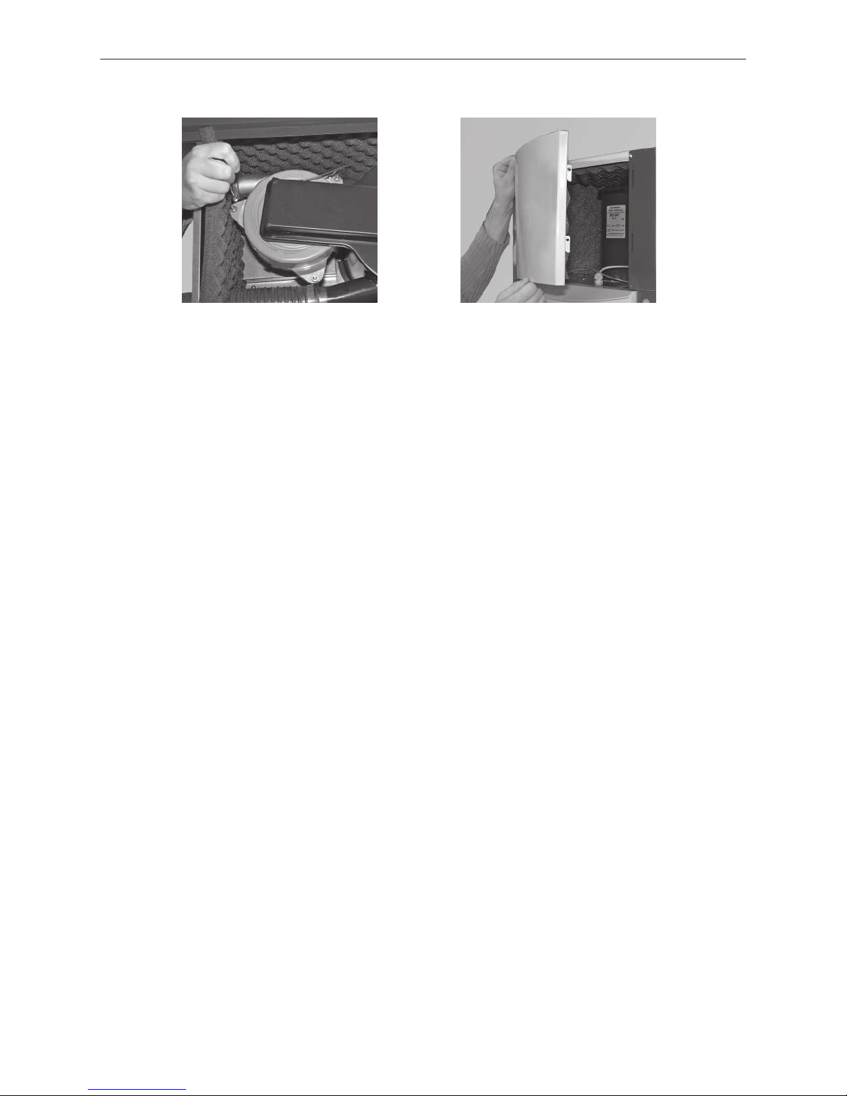
– Supply and return air hose assembly:
1. Loosen cover of feed unit (2 screws at front and 2 screws at rear) – Fig. 63.
2. Remove the cover.
Alternatively, the rear wall can be removed instead of removing the top cover.
3. Expose approx. 5 cm of the flexible earth leads on all hose ends and bend inwards into the hose Fig. 64.
Important: Also refer to assembly instructions for supply and return air hose in enclosed manual for sto-
rage room accessories (changeover unit).
4. Thread hoses through rear wall and sound insulation mat and connect to suction turbine or cyclone – Fig. 65.
5. Assemble in reverse order.
Page 22
22
2. For the Installer
2.15 Initial start-up and operating instructions
Windhager Customer Service or the customer service partner will start up the boiler first of all, and will familiarize the customer with the system operation and cleaning of the boiler, with reference to the Operating Manual.
The following preconditions must be met before you order the initial start-up:
1.) Boiler installed correctly.
2.) System fully wired up electrically.
3.) System rinsed, filled and vented – heat consumption must be possible.
4.) Boiler connected to domestic water and filled.
5.) Sufficient quantity of fuel available (pellets, split logs, oil or gas).
6.) The customer must be present during start-up.
The initial start-up cannot be carried out if any of these points are neglected. The customer will be charged
for any unnecessary costs arising as a result.
Start-up and maintenance by Windhager Customer Service or a customer service partner are part of the guarantee requirements of the enclosed “guarantee limitations”.
– Hook in cladding cover at front – Fig. 66.
– For electric connection of feed unit, see section 3.1.
Fig. 65 Supply and return air hose assembly
Fig. 66 Hooking in cladding cover
Page 23
23
3. For the Electrician
3. For the Electrician
3.1 Electrical connections
The boiler and related accessories are designed to be installed only in dry areas (protection type IP 10). Installation of electrical components may only be performed by a qualified technician. The regulations and specifications
of ÖVE, VDI, SEV and local ordinances must be followed.
Attention!
– The mains connection must be protected against short circuit with a 13 A delayed-action fuse.
– On site, the technician must install an all-pole disconnection with at least 3 mm contact gap at
the mains access point. Current-operated r.c.d. or frequency conversion protection switches
are considered all-pole disconnections (ÖVE regulation).
We recommend using fine-wire PVC sheathed cables, e.g., H05VV-F (YMM-J) with a 3 x 1.5 mm
2
nominal crosssection.
Two separate cables are required for connecting the changeover unit (located in the pellet store).
– Cable for limit switch (extra-low voltage): min. 3 x 0.5 mm2 (no earth), we recommend using a shielded cable if
the cable is longer than 5 m.
– Cable for changeover unit motor (low voltage): 4 x 1.5 mm
2
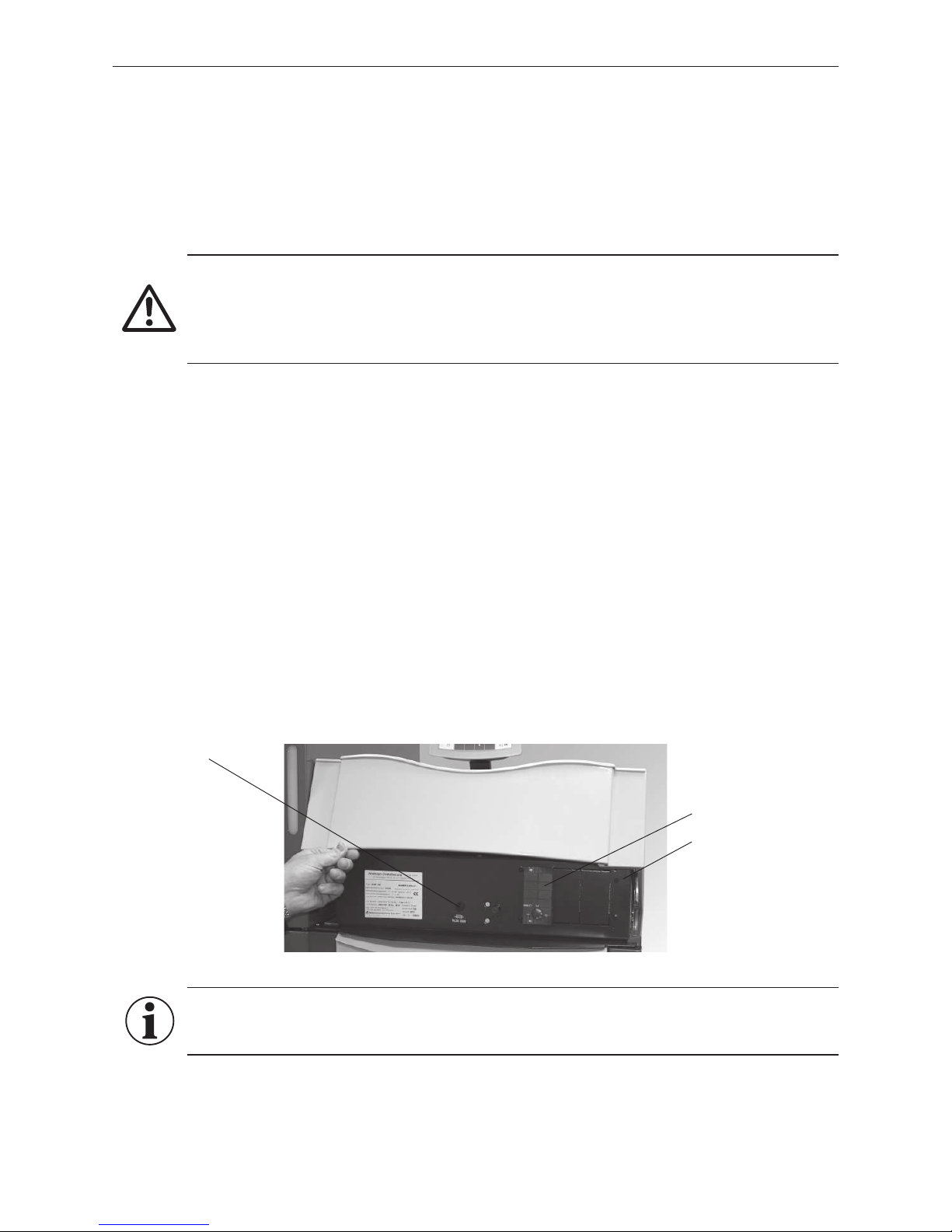
The boiler is pre-wired and internally fused with a T 6.3 A fine-wire fuse to protect against short circuit. By special
order, up to 3 MESplus modules (including boiler sensor) will be installed in the control panel and wired at the
factory – Fig. 67. if there are more than 3 modules, they are installed in the wall-mount casing (accessory: MES
004) and need to be electrically wired on site.
Maximum MESplus module switching capacity: Relay outputs: 230 V AC, 6 A (2 A inductive), 50 Hz
WVF and B-PLM modules with X1/X2 contact: Solid-state relay: 230 V AC, 1 A
The electrical rating is dependent upon the number of modules installed in the unit, that is, the number of actuators powered (pumps, mixing valves, etc.).
In areas with increased power surge risk (e.g., lightning strikes in regions prone to storms), we recommend installation of an appropriate surge protector.
Fig. 67 Control panel BioWIN 100–260
Information!
Electrical cables must not touch heating and exhaust pipes, nor must they come in contact with no-
ninsulated boiler components. They are to be sufficiently braced and provided with a protective tube.
All electrical connections are located in the control panel. The control panel is set up on 2 levels (control panel
top part and control panel bottom part). The control panel top part contains the BioWIN main board while the
control panel bottom part contains the connection terminals (screwless spring-type terminals) for connecting the
MESplus control.
Fuse T 6.3 A
MESplus module
Control panel
Page 24
24
3. For the Electrician
To access the various levels of the control panel:
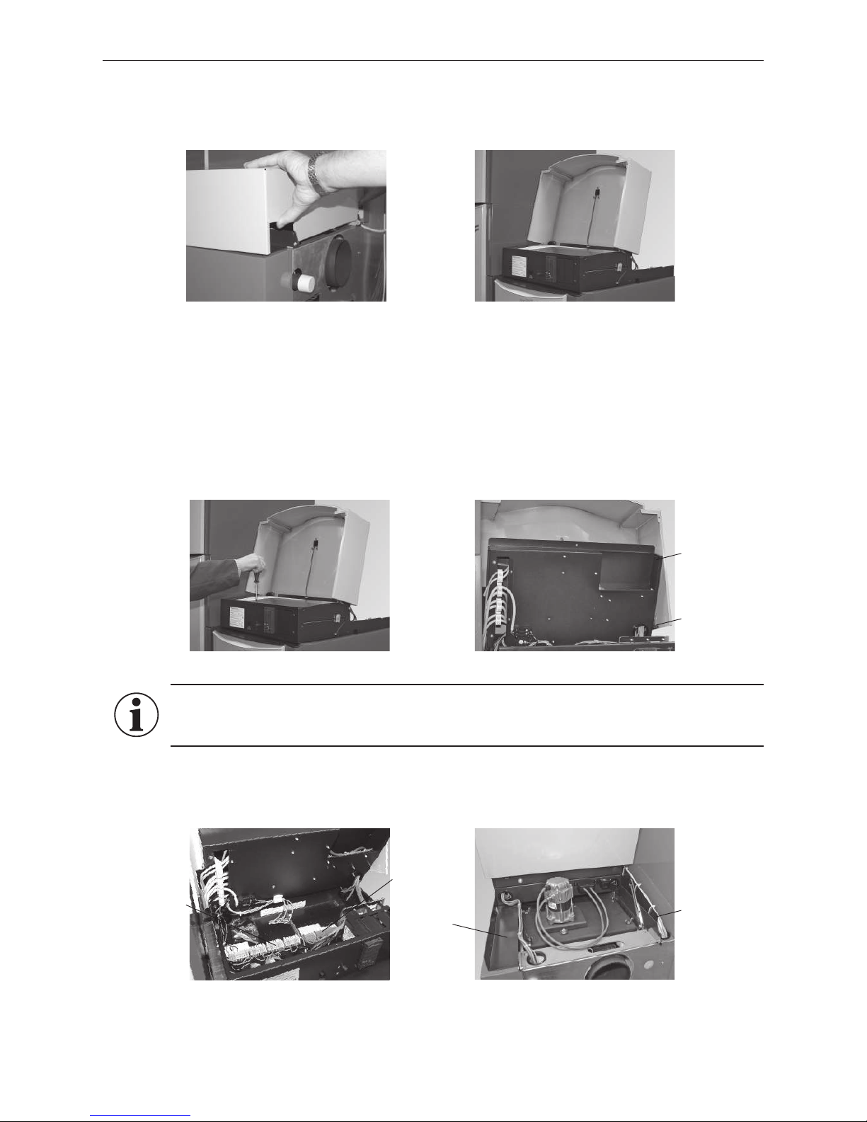
– Raise cladding cover at rear, unhook and pull backwards – Fig. 68.
– Fold up cladding cover – Fig. 69.
Fig. 68 Taking off cladding cover at rear Fig. 69 Folding up cladding cover at front
Fig. 70 Loosen screw at front Fig. 71 Folding up control panel top part
Fig. 72 Control panel bottom part with
terminal blocks
Fig. 73 Cable ducts - rear view
3.1.1 Electrical connection for control and changeover unit
The connections (screwless spring-type terminals) for the control systems are located in the control panel bottom
part. Connection diagrams for the control are enclosed and for the changeover unit, see section 4.9.
To enter the control panel bottom part, the control panel top part must be folded up. To do this, loosen the front screw
on the control panel (Fig. 70) and fold up the control panel top part until it snaps into the lock at the side – Fig. 71.
Information!
Be sure to note the separate wiring of the extra-low voltage line (sensor) and low-voltage line
(230VAC)! – Fig. 73.
The connection to the terminal blocks (screwless spring-type terminals) should be made using fine-wire PVC
sheathed cables and the cables are not allowed to be too short or under tension in the cable ducts. This is to allow
the control panel to be folded open even when the cables are connected – Fig. 72, 73.
To close the control panel top part again, loosen the side lock and fix again with screw at front.
Control panel
top part
Lock
Cable duct
Low-voltage
(230 V AC)
Extra-low voltage (sensor)
Cable duct
Extra-low voltage (sensor)
Low-voltage
(230 VAC)
Page 25
25
3. For the Electrician
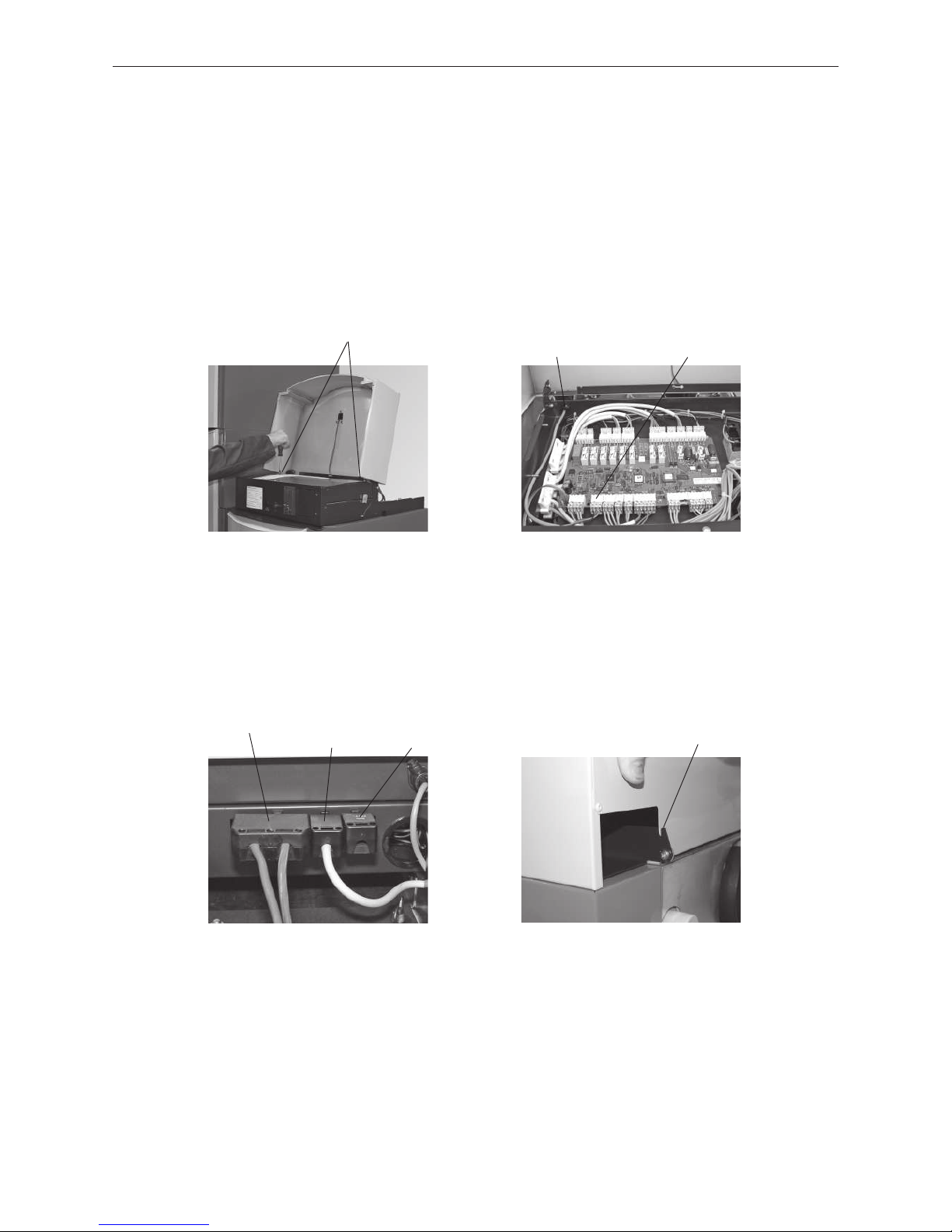
Fig. 74 Loosening 2 screws Fig. 75 Connecting proximity switch of
feed unit
3.1.2 Electrical connection for control and changeover unit
The feed unit has 2 cables running to the BioWIN, 1 x proximity switch and 1 x 230 V AC power supply.
Proximity switch:
The proximity switch is connected in the control panel top part. To access the control panel top part, unscrew the
2 screws on the side of the control panel cover (Fig. 74) and lift off the cover.
Remove blind plugs and guide cable of proximity switch with strain relief (must snap into opening) from rear into
the control panel and connect – Fig. 75.
Refit control panel cover with 2 screws and close cladding cover at front.
2 screws
Fig. 76 Connecting plugs – rear view Fig. 77 Attaching cladding cover at rear -
rear view
Power supply 230 V AC (mains plug):
Connect mains plug for feed unit at rear near control panel – Fig. 76.
Plug rear cladding cover at rear into fastening – Fig. 77.
Opening for
strain relief
Plug for
proximity switch
Blower plug Feed unit
mains plug
Devices
power plug
Insert cladding cover at rear in
groove hinges
Page 26
26
4. For the Service Technician
4. For the Service Technician
4.1 Start-up and operating instructions
The Windhager Customer Service or Partner Customer Service will start up the boiler and will familiarize the
customer with the system operator and cleaning of the boiler. Start-up and maintenance are part of the guarantee
requirements of the “warranty conditions” – see also section 2.15.
We recommend that you obtain a maintenance service contract.
4.2 Service and repair work
Service and repair may be performed only by appropriately qualified technicians.
Please note:
Disconnect the mains power plug before opening the control panel for service or repair purposes. Raise cladding
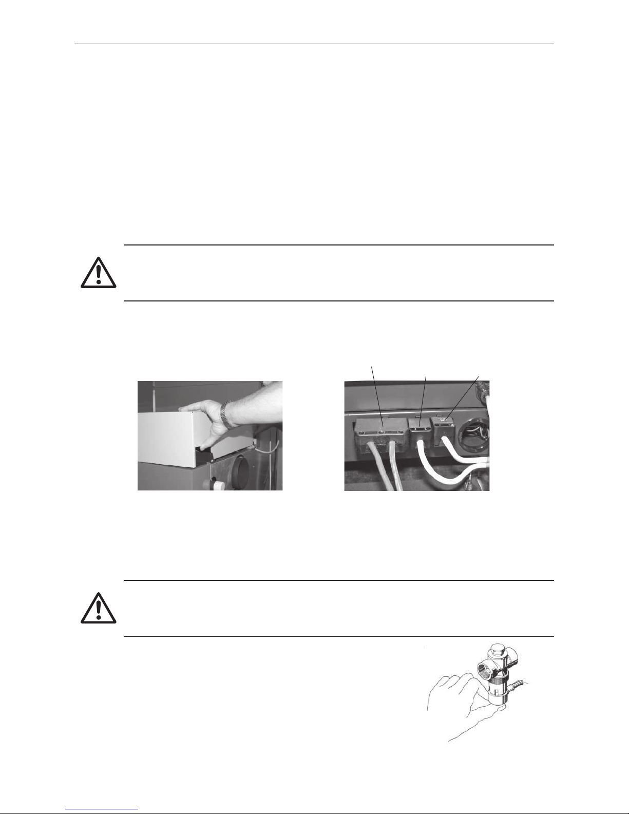
cover at rear, unhook and pull backwards – Fig. 78. Disconnect the mains power plug – Fig. 79.
Fig. 78 Taking off cladding cover at rear Fig. 79 Disconnecting mains power plug
Blower plug Feed unit
mains plug
Devices
power plug
Attention!
After the emergency shut-off switch trips, the boiler and accessories are not completely without
power! When replacing system components (pumps, mixing valves, etc.) prevent all power input (e.g.
by removing the mains power plug).
4.3 Checking and servicing the thermal process safeguard
(Not needed for all boiler models, only if the boiler has a thermal safety device. Please inform your customer)
Attention!
The function of the thermal process safeguard must be checked once a year by a technician and the
amount of limescale in the thermal safety device must be checked. If there is limescale in the thermal
safety device then it must always be removed.
- Press the red cap against the valve (Fig. 80) > Water must flow out into
the funnel.
- Little outflow at funnel > Limescale in thermal safety device (pump limes-
cale remove – e.g. formic acid – through the thermal safety device).
- Thermal process safeguard dripping > Clean the seal on the piston and
valve seat. If the seal is damaged > Renew the piston.
Note: There is no need to remove the fitting for this purpose!
Fig. 80 Thermal process safeguard, pres-
sing red cap against valve
Page 27
27
4. For the Service Technician
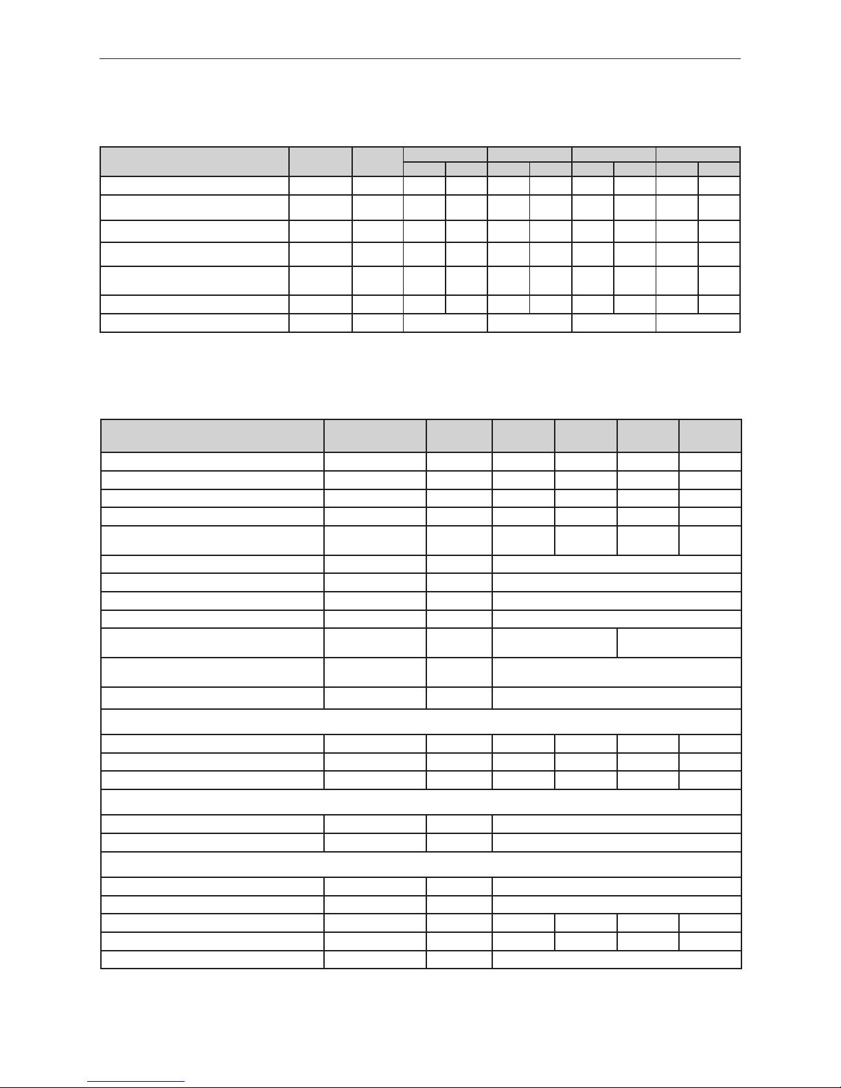
4.4 Technical data for calculating the flue gas system acc.
to EN 13384-1
BioWIN pellet boiler
Formula
symbols
Unit
BW 100 BW 150 BW 210 BW 260
min. max. min. max. min. max. min. max.
Nominal thermal output Q
N
kW 2,9 9,9 4,3 15,0 6,1 21,0 7,5 25,9
Nominal heat load
(firing thermal output)
Q
B
kW 3,3 10,9 4,8 16,4 6,7 22,5 8,3 27,6
Volume concentration of CO
2
σ (CO2) % 10,6 13,4
9,2 13,6 10,1 14,1 10,6 14,6
Flue gas mass flow rate - rated load
.
m
kg/s 0,0023 0,0061 0,0038 0,0090 0,0048 0,0120 0,0057 0,0142
Flue gas temperature - rated load
(Average between two cleaning intervals)
T
W
°C 77 111 85 129 91 140 95 150
Necessary feed pressure P
W
Pa 0 5 0 5 0 5 0 5
Flue gas connection diameter Ø mm 130 130 130 130
4.5 Technical data – General
BioWIN pellet boiler Unit BW 100 BW 150 BW 210 BW 260
Boiler class according to EN 303-5 3 3 3 3
Nominal thermal output range kW 2,9 – 9,9 4,3 – 15,0 6,1 – 21,0 7,5 – 25,9
Radiation losses rated load kW 0,32 0,33 0,34 0,36
Boiler water volume l 59
59 53
53
Water-side resistance
∆T = 20 °K
∆T = 10 °K
mbar
1,3
5,0
2,9
11,2
5,6
21,6
7,0
26,7
Boiler temperature control range °C 60 – 75
Operating pressure max. bar 3
Test pressure bar 4,5
Pellet reservoir l / kg 232 / 150,8
Net weight of fully assembled boiler
Exklusive / Premium / Klassik
kg 333 / 318 / 318 344 / 329 / 329
Dimensions (W x D x H)
Exklusive / Premium / Klassik
mm
1028 x 733 x 1745 / 1102 x 733 x 1745 /
1102 x 733 x 1461
Installation dimensions (W x D x H)
(Please note: separate installation possible)
mm 1200 x 790 x 1610
Values from type test Testing office TÜV SÜD Munich, test report no.: 1190-01/08, 1190-02/08)
Firing efficiency (100-qA)
rated load / part load % 96,1 / 98,0 94,7 / 98,1 94,4 / 97,4 94,2 / 96,7
Boiler efficiency η
W
rated load
% 93,2 92,7 92,8 92,9
Flue gas temperature rated load / part load °C 91 / 62 109 / 70 120 / 75 130 / 80
Electrical power consumption of pellet feed:
Automatic pellet feed W 1748
Maximum current consumption, pellet feed A 8,1
Electrical power consumption of pellet boiler:
maximum current consumption A 5,8
maximum for igniting W 1060
Ignition process Wh 143 141 170 170
Heating operation rated load / part load W 46 / 27 58 /32 100 / 40 110 /47
Idle operation W 7
Page 28
28
4. For the Service Technician
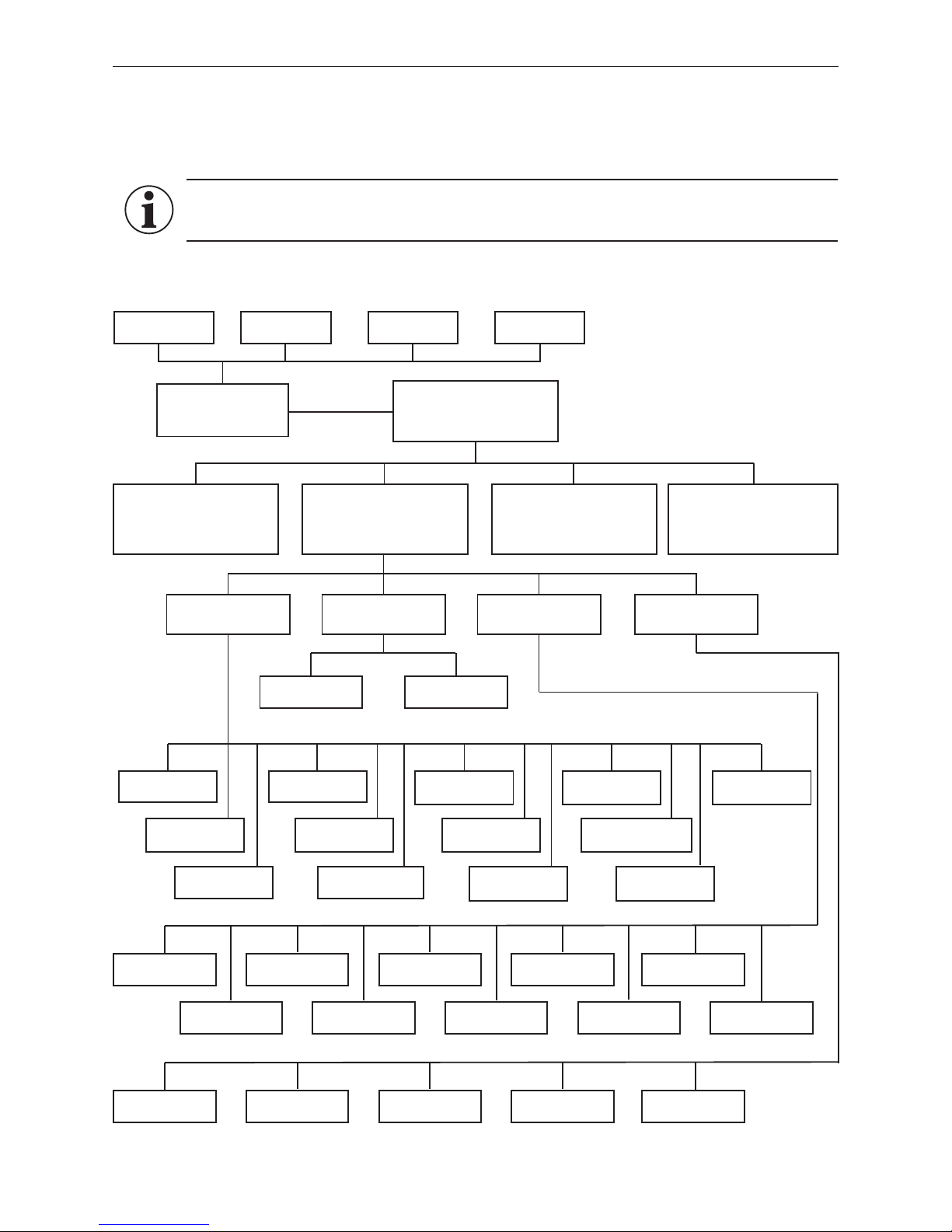
4.6 Service level
System parameters, start-up or actuator test can be displayed, modified and/or performed on the Service level.
Structure on the Service level:
Information!
Only trained service personnel may perform system modifications on the Service level.
Actuator test
Menu
Number of burner
starts
Fuel quantity
auger conveyor
Operating time of
suction turbine
Maximum value of
set temperature
Hysteresis
burner ON
Type of pellet feed
system
Ash removal
profile
Flue gas thermostat or
Air intake/ exhaust flap
Parameters Start-up
Auger conveyor Feed
Induced draught fan
Auger conveyor
Ash removal Suction turbine
Ignition element
Ash removal
Heating surfaces
cleaning
Probe
switching
Air intake/exh. flap
Pumping time
ignition phase
Set temperature ext.
heating requirement
Cleaning interval
correction
Limits for
blower speed
Boiler pump
Settings
Install display
module
Language selection Time formatTemperature format Date format
Minimum operating
time with buffer
Operator level
Settings on the operator level
see BioWIN Operating Manual.
Service level
Reserved for trained service
personnel only.
Information level
(see BioWIN Operating Manual)
MES Module
1
(see separate instructions for
InfoWINplus Master operation)
InfoWINplus basic
settings
(see section 4.7)
Language selection Boiler SMSMB
1 only displayed when an MESplus control is present and this has been adjusted by a trained service technician in the basic settings
Page 29
29
4. For the Service Technician
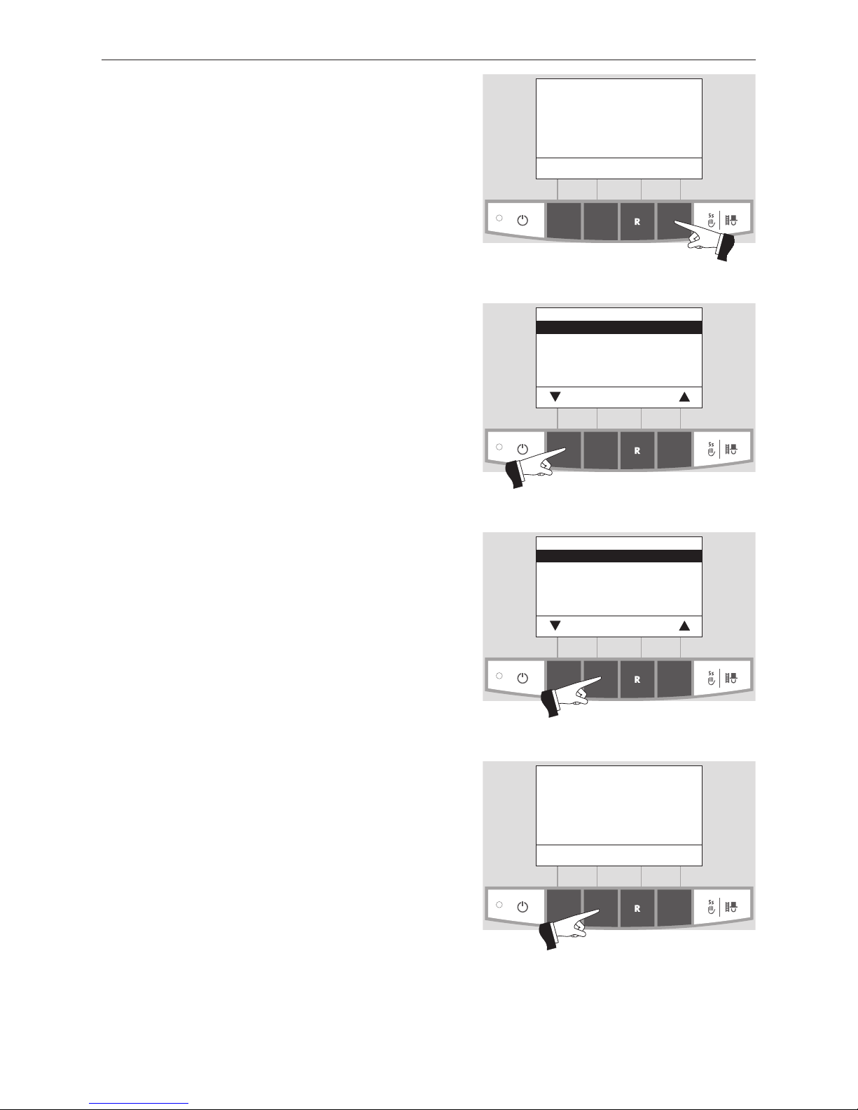
Fig. 81
Boiler temperature
(Operating phases)
Info Menu
42
°C
Service level
Pressing the Menu button (Fig. 81) shows the „Operator level“, „Service level“, „Information level“ and „MES Module1“
in the display – Fig. 82.
Fig. 82
Operator level
Service level
Information level
MES Module
1
Choose Back
Fig. 83
Operator level
Service level
Information level
MES Module
1
Choose Back
Fig. 84
Service level only
for trained service personnel
5s
Use the arrow buttons to select the “Service level” submenu – Fig. 82.
Press and hold the Choose button for 5 seconds (Fig. 83).
The display shows „Service level only for trained service
personnel“ – Fig. 84.
Press for 5
seconds
Press for 5
seconds
1 only displayed when an MESplus control is present and this has been adjusted by a trained service technician in the basic settings
Page 30
30
4. For the Service Technician
Select the required item, „Parameters“, „Start-up“, „Actuator test“ or „Settings“ and confirm by pressing the Choose
button – Fig. 85.
For further settings, see sections 4.6.1 - 4.6.4.
Fig. 85
Parameters
Start-up
Actuator test
Settings
Choose Back
Fig. 86
Parameters
Start-up
Actuator test
Settings
Choose Back
The menu item or sub-menu item is exited by pressing the
Back button or after a delay of 45 seconds – Fig. 86.
4.6.1 Parameters
The following parameters can be selected with the arrow buttons, then confirmed using the Choose button.
– Number of burner starts
– Fuel quantity auger conveyor
– Delivery time ignition phase
– Hysteresis Burner ON
– Maximum value of set temperature
– Set temperature ext. heating requirement
– Type of pellet feed system
– Operating time of suction turbine
– Ash removal profile
– Cleaning interval correction
– Flue gas thermostat or Air intake/ exhaust flap
– Limits for blower speed
– Minimum operating time with buffer
Page 31
31
4. For the Service Technician
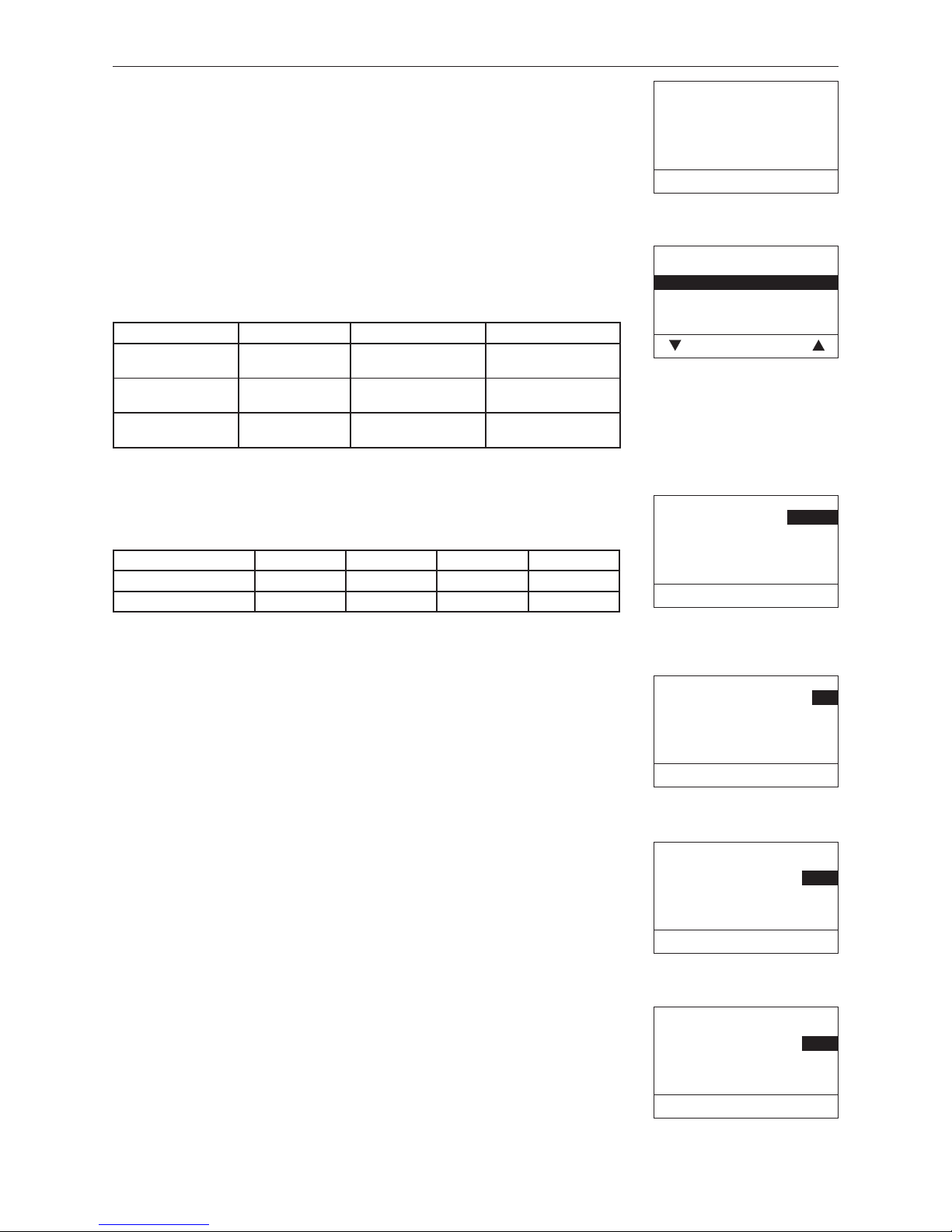
Number of burner starts
The number of burner starts of the BioWIN is displayed.
Fig. 87
Number of burner starts
1.350
Back
Fig. 88
Fuel quantity
Auger conveyor
Actual value 6.5 kg
Range 11.5 kg
Correction 0
Choose Back
Fuel quantity auger conveyor
The calculated fuel quantity (actual value) and the range is displayed in kg/h,
and can be adjusted.
BioWIN BW 100/150 BW 210/260
Actual
value
Factory setting:
Setting range:
6,5 kg/h
±3 kg of range
11,5 kg/h
±3 kg of range
Range
Factory setting:
Setting range:
6,5 kg/h
6,5 – 8,5 kg/h
11,5 kg/h
11,5 – 13,5 kg/h
Correction
Factory setting:
Setting range:
0
±5
0
±5
Fig. 89
Delivery time ignition phase
Actual value 120 s
min. 96 s
max. 144 s
– Save Back +
Fig. 90
Hysteresis Burner ON
Actual value 5 K
min. 0 K
max. 20 K
– Save Back +
Delivery time ignition phase
Fuel quantity in the ignition phase.
BioWIN BW 100 BW 150 BW 210 BW 260
Factory setting: 120 s 90 s 110 s 85 s
Setting range: 96 – 144 s 72 – 108 s 88 – 132 s 68 – 102 s
Hysteresis Burner ON
Switching hysteresis for burner control.
Factory setting: 5 K
Setting range: 0 – 20 K
Fig. 91
Maximum value of
set temperature
Actual value 75 °C
min. 60 °C
max. 75 °C
– Save Back +
Maximum value of set temperature
This is the maximum setpoint achievable in normal heating operation.
Factory setting: 75 °C
Setting range: 60 – 75 °C
Fig. 92
Set temperature ext.
heating requirement
Actual value 70 °C
min. 35 °C
max. 75 °C
– Save Back +
Set temperature ext. heating requirement
This is the set temperature for external heating requirement.
Factory setting: 70 °C
Setting range: 35 – 75 °C
Page 32
32
4. For the Service Technician
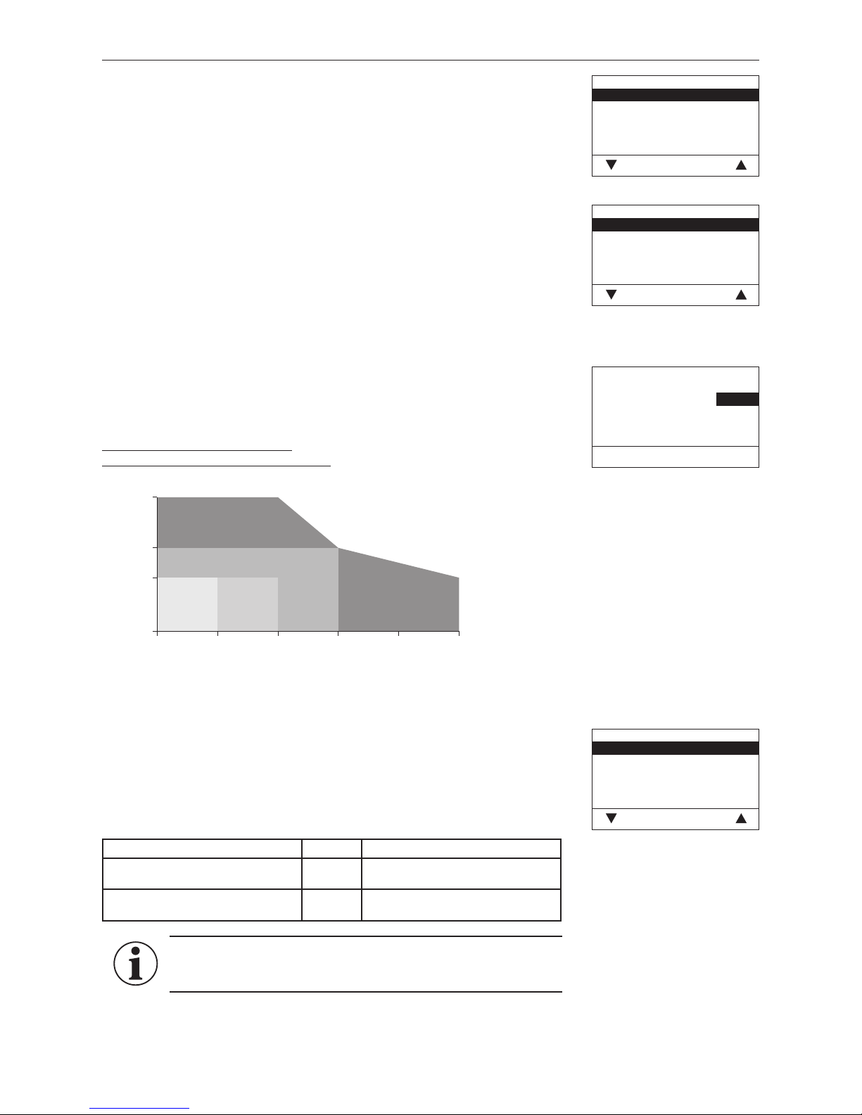
Type of pellet feed system
Setting for whether operation is without feed system, with 2 or 8 probes or with
mixer (buried tank).
Factory setting: without feed system
The following settings are available:
For changeover unit with 3 probes: Suction turbine with 2 probe
Suction turbine with 3 probe
For changeover unit with 8 probes: Suction turbine with 4 probe
Suction turbine with 6 probe
Suction turbine with 8 probe
For buried tank with mixer
and for solo probe: Suction turbine with mixer
Fig. 93
Type of pellet feed system
without feed system
Suction turbine with 2 probe
Suction turbine with 3 probe
Suction turbine with 4 probe
Suction turbine with 6 probe
Choose Back
Fig. 94
Type of pellet feed system
Suction turbine with 8 probe
Suction turbine with mixer
Choose Back
Operating time of suction turbine
Factory setting: 30 sec.
Einstellbereich: 20 – 70 sec.
Diagram for suction time setting
by feed hose length and suction height:
Fig. 95
Operating time of
suction turbine
Actual value 30 sec.
min. 20 sec.
max. 70 sec.
– Save Back +
0 5 10 15 20 25
0
<30 s 4 0 s 50 s
>60 s
1,8
2,8
4,5
>60 s
max. suction height (m)
max. feed hose length (m)
Ash removal profile
This adjuster can be used to adjust the removal of ash from the burner pot for
different stages of pellet quality.
Factory setting: Stage 1
Fig. 96
Ash removal profile
Stage 0
Stage 1
Stage 2
Stage 3
Save Back
Information!
Restore factory setting for next delivery of pellets.
Stage 0 to Stage 3
very low proportion of ash very high proportion of ash
(possibly formation of slag)
no ash removal in
modulation mode
frequent ash removal in
modulation mode
Page 33
33
4. For the Service Technician
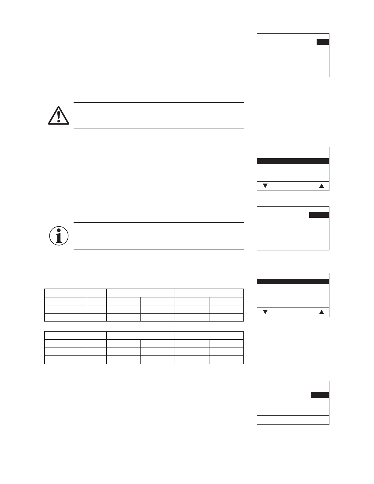
Cleaning interval correction
The cleaning interval is basically dependent on the proportion of ash in the pellets and the ash removal profile. This adjuster can be used to extend or shorten
the cleaning interval by +/-50%.
The standard setting is a cleaning interval determined by testing.
Factory setting: 0 %
Setting range: ±50 %
Fig. 97
Correction of Cleaning interval
Actual value
0 %
min. -50 %
max. +50 %
– Save Back +
Attention!
If too long a cleaning interval is selected, the ash container may
overfill.
Flue gas thermostat or Air intake/ exhaust flap
This adjuster can be used to change the flue gas thermostat function (factory
setting) to air intake/ exhaust flap.
Factory setting: Flue gas thermostat
With air intake/ exhaust flap setting (Fig. 99):
Factory setting: Operating time 300 sec.
Setting range: 30 – 600 sec.
Fig. 98
Flue gas thermostat or Air intake/ exhaust flap
Flue gas thermostat
Air intake/exh. flap
Choose Back
Information!
The set operating time should be twice as long as the actual operating time of the Air intake/exh. flap.
Limits for blower speed
BW 100 BW 150
Minimum Maximum Minimum Maximum
Factory setting: rpm 1000 2000 1100 2600
Setting range: rpm 1000–1300 2000–2400 1100–1400 2600–2700
BW 210 BW 260
Minimum Maximum Minimum Maximum
Factory setting: rpm 950 2200 1000 2700
Setting range: rpm 950–1250 2200–2600 1000–1300 2700–2700
Minimum operating time with buffer
This function is not yet available.
Fig. 99
Air intake/exh. flap
Operating time 300 sec.
min. 30 sec.
max. 600 sec.
– Save Back +
Fig. 100
Limits for blower speed
Minimum 1050 rpm
Maximum 1950 rpm
Choose Back
Fig. 101
Minimum operating time
with buffer
Actual value 60 min.
min 0 min.
max 180 min.
– Save Back +
Page 34
34
4. For the Service Technician
4.6.2 Start-up
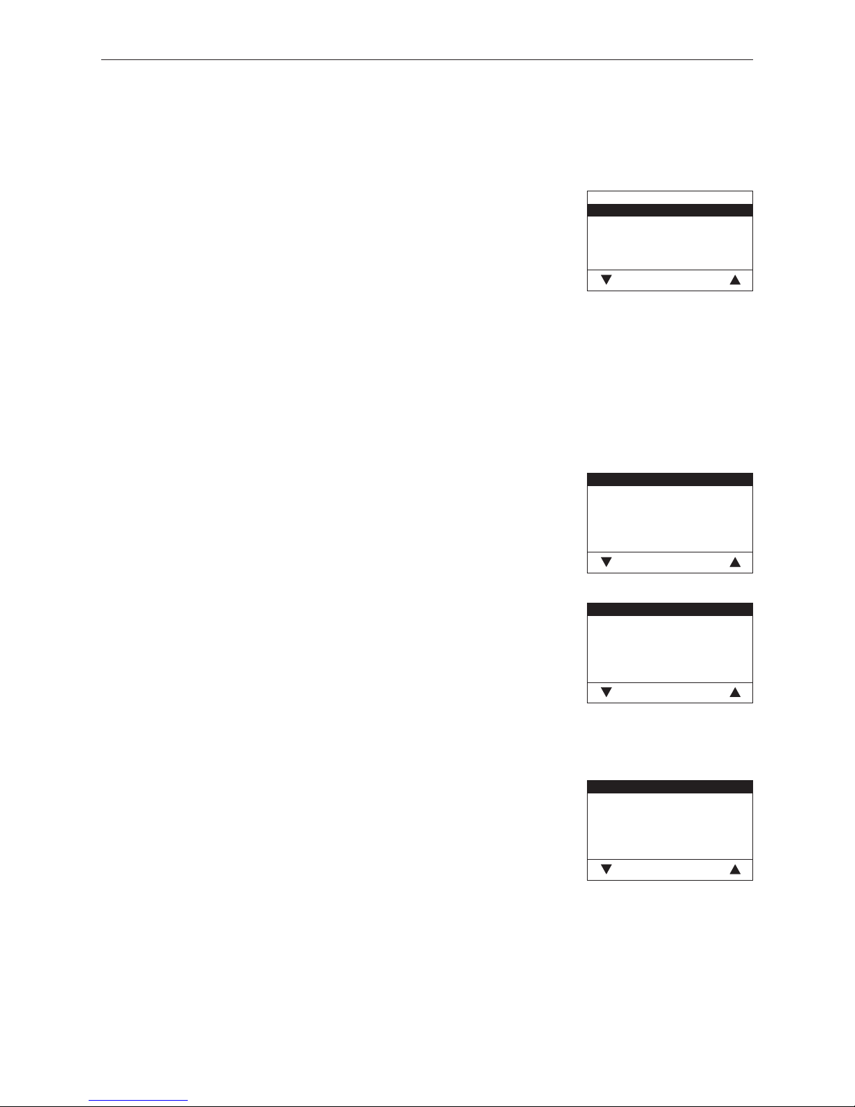
The auger conveyor and the feed can be selected on the Start-up level with the arrow buttons, then confirmed or
selected using the Choose button. A self-test is started at the end of the start-up.
Fig. 102
Start-up
Auger conveyor
Feed
Choose Back
Auger conveyor
The auger conveyor can be switched on for 6 minutes.
Feed
Depending on the set feed system, the feed and each probe incl. purging can be
started up.
4.6.3 Actuator test
The following actuators can be selected with the arrow buttons, then confirmed and started using the Choose
button. The actuators are switched off again after 1 minute. A self-test is started at the end of an actuator test.
Fig. 103
Induced draught fan
Auger conveyor
Ash removal
Ignition element
Ash removal
Heating surf. cleaning
Choose Back
– Induced draught fan
– Auger conveyor
– Ash removal
– Ignition element
– Ash removal
– Heating surface cleaning
– Suction turbine
– Probe switching
– Air intake/exh. flap
– Boiler pump
Fig. 104
Suction turbine
Probe switching
Air intake/exh. flap
Boiler pump
Choose Back
4.6.4 Settings
This sub-menu contains the following settings:
– Install display module
– Language selection
– Temperature format
– Time format
– Date format
– Weight
Fig. 105
Install display module
Language selection
Temperature format
Time format
Date format
Weight
Choose Back
Page 35
35
4. For the Service Technician
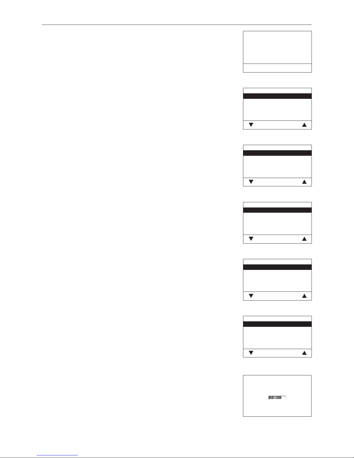
Install display module
Is not needed with an individual BioWIN boiler, only needs to be used with a
cascade system – see “Planning and assembly” instructions for pellet cascade.
Fig. 106
Start installation procedure
Please press LON button on automatic firing device briefly
Back
Fig. 107
Language selection
Deutsch
English
Française
Italiano
Choose Back
Language selection
The InfoWINplus can show the display texts in various languages. The language
required can be selected in this sub-menu.
Fig. 108
Temperature format
°C
°F
Choose Back
Temperature format
All temperatures are displayed in the chosen format (e.g. 30.6 °C or 87.0 °F).
Factory setting: °C
Selection: °C and °F
Fig. 109
Time format
24h
12h
Choose Back
Time format
The time is displayed in the chosen format (e.g. 14:12 or 02:12 PM).
Factory setting: 24 h
Selection: 24 h or 12 h
Fig. 110
Date format
DD.MM.YYYY
MM/DD/YYYY
Choose Back
Date format
The date is displayed in the chosen format (e.g. Wed 17.02.2010 or Wed
02/17/2010).
Factory setting: DD.MM.YYYY
Selection: DD.MM.YYYY
MM/DD/YYYY
Fig. 111
Weight
t, kg
tn. sh., lbs
Choose Back
Weight
The weight is displayed in the chosen format (e.g. 6.5 kg or 14.3 lbs).
Factory setting: t, kg
Selection: t, kg or tn. sh., lbs
4.6.5 Installation of MESplus modules
Display if an MESplus module is installed (connected) or uninstalled
(disconnected).
Fig. 112
Installation procedure active
(Animated symbol)
Page 36
36
4. For the Service Technician
4.7 InfoWINplus basic settings
Information!
Only trained service personnel may perform modifications in the basic settings.
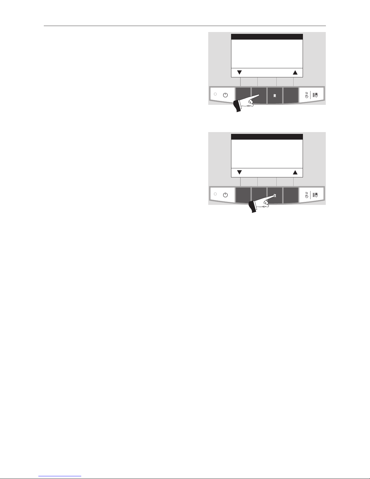
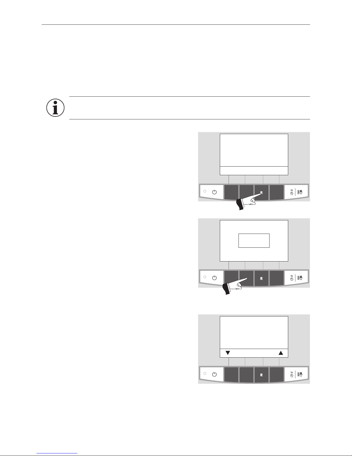
The display switches to the basic settings when „Version ....“
(Fig. 114) is displayed and the button (shown in Fig. 114) is
pressed for 5 seconds.
„Version ...“ is displayed,
– if the „R“ button is pressed for 5 seconds on a standard
display – Fig. 113;
– if the InfoWINplus was de-energised and then switched
on.
The following settings are available in the basic settings:
– Language selection
– Boiler
– MB
– SMS
Fig. 113
Boiler temperature
(Operating phases)
Info Menu
42
°C
Fig. 114
Version V2.00
16.3.2012
Press for
5 seconds
The basic settings are used to
– set whether the InfoWINplus controls a wood or pellet boiler or whether it is solely used as master operation;
– switch the master operation functions on and off;
– activate/deactivate remote switching by text message.
The basic settings are undertaken in the factory before delivery as per the order.
Fig. 115
Language selection Deutsch
Boiler No
MB No
SMS No
Choose Back
Page 37
37
4. For the Service Technician
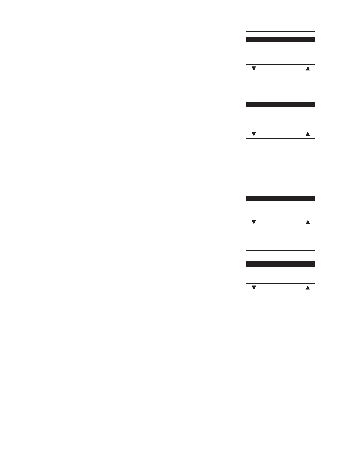
Fig. 117
Boiler
Pellets
Wood
Heating oil
No
Save Back
Boiler
Setting to determine what kind of boiler the InfoWINplus controls, e.g. wood or
pellet boiler or whether it is solely used as master operation.
Factory setting: is set in the factory before delivery as per the order.
Selection: Pellets: BioWIN, BioWIN XL, FireWIN, VarioWIN usw.
Wood: LogWIN, SilvaWIN usw.
Heating oil: JetWIN, EcoWIN
No No boiler, e.g. for MultiWIN, simply master
operation for remote switching
Fig. 118
MB
Yes
No
Save Back
MB (Master operation)
Setting to define whether MESplus system control is present.
Factory setting: is set in the factory before delivery as per the order.
Selection: yes: with MESplus system control
no: no MESplus system control
Fig. 119
SMS
Yes
No
Save Back
SMS
Setting to define whether remote switching by text message is possible.
Factory setting: is set in the factory before delivery as per the order.
Selection: yes: with remote switching
no: no remote switching
Fig. 116
Language selection
Deutsch
English
Française
Italiano
Choose Back
Language selection
The InfoWINplus can show the display texts in various languages. The language
required can be selected in this sub-menu.
Page 38
38
4. For the Service Technician
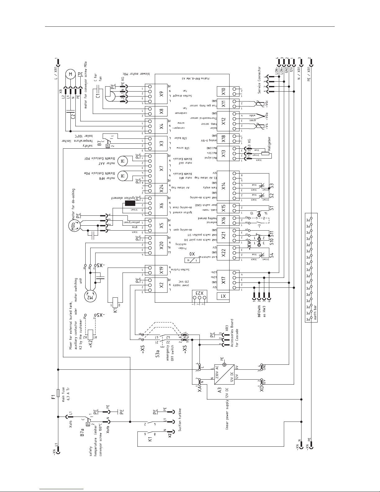
4.8 Basic BioWIN 100–260 circuitry
092175/02
Page 39
39
4. For the Service Technician
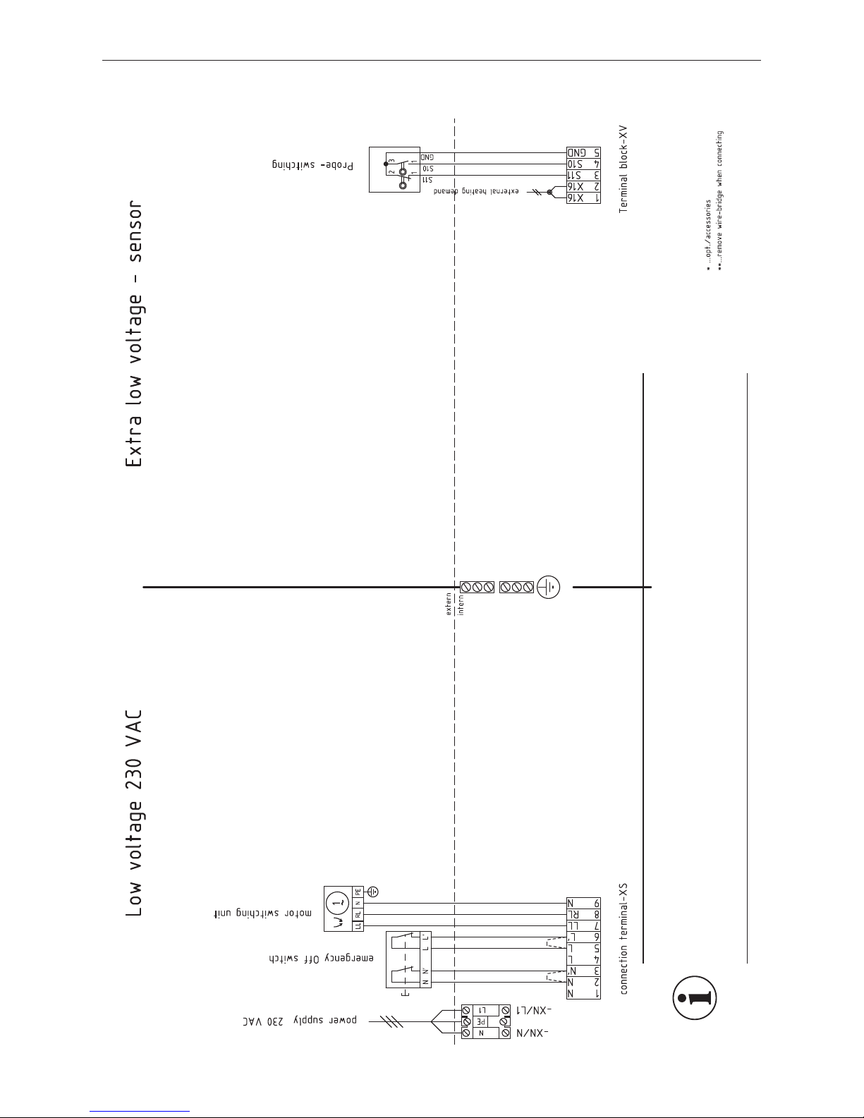
4.9 BioWIN 100–260 connecting diagram
091505/00
Information!
Two separate cables are needed to connect the changeover unit.
– Cable for limit switch (extra-low voltage): min. 3 x 0.5 mm
2
(no earth), we recommend using a
shielded cable if the cable is longer than 5 m.
– Cable for changeover unit motor (low voltage): 4 x 1.5 mm
2
Page 40
40
4. For the Service Technician
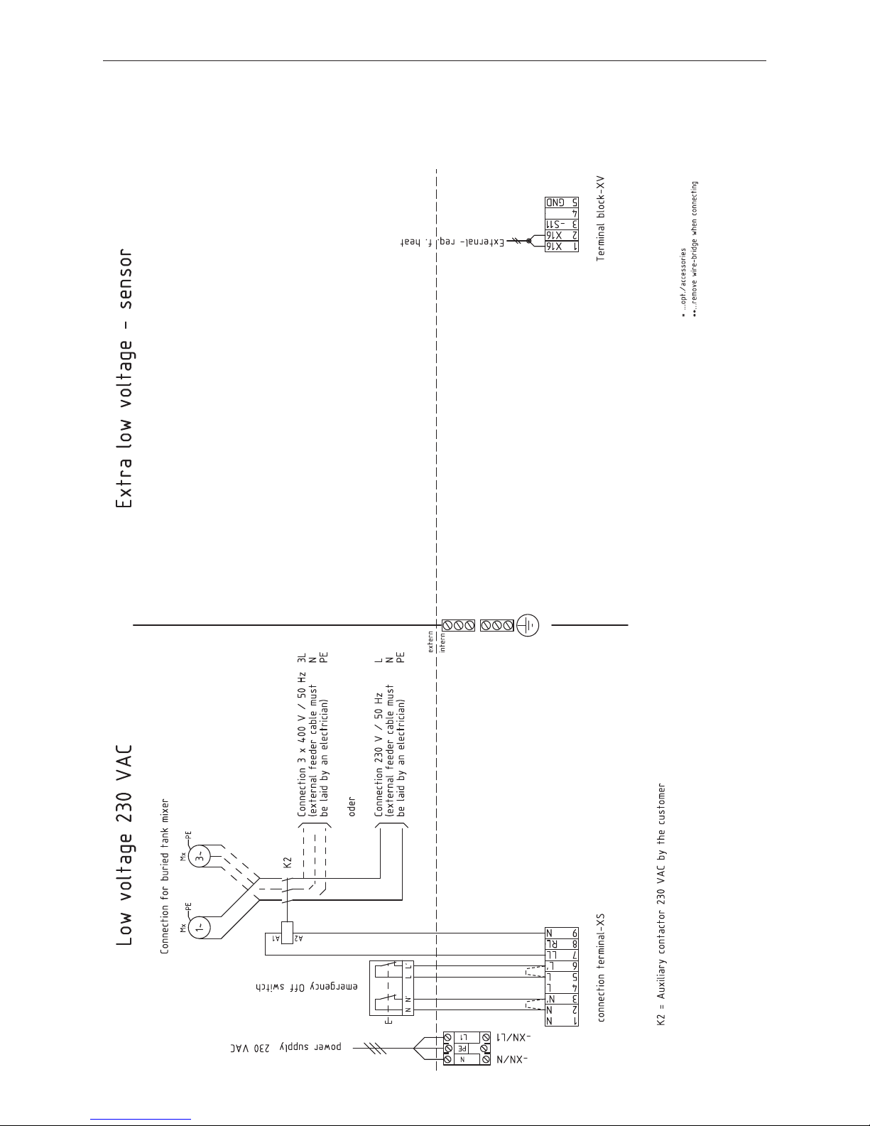
4.10 BioWIN 100-260 pellet feed connecting diagram with
mixer for buried tank
Operation with a mixer must be set on the service level – see section 4.6.1 Parameters; type of pellet feed system.
091673/00
Page 41
41
4. For the Service Technician
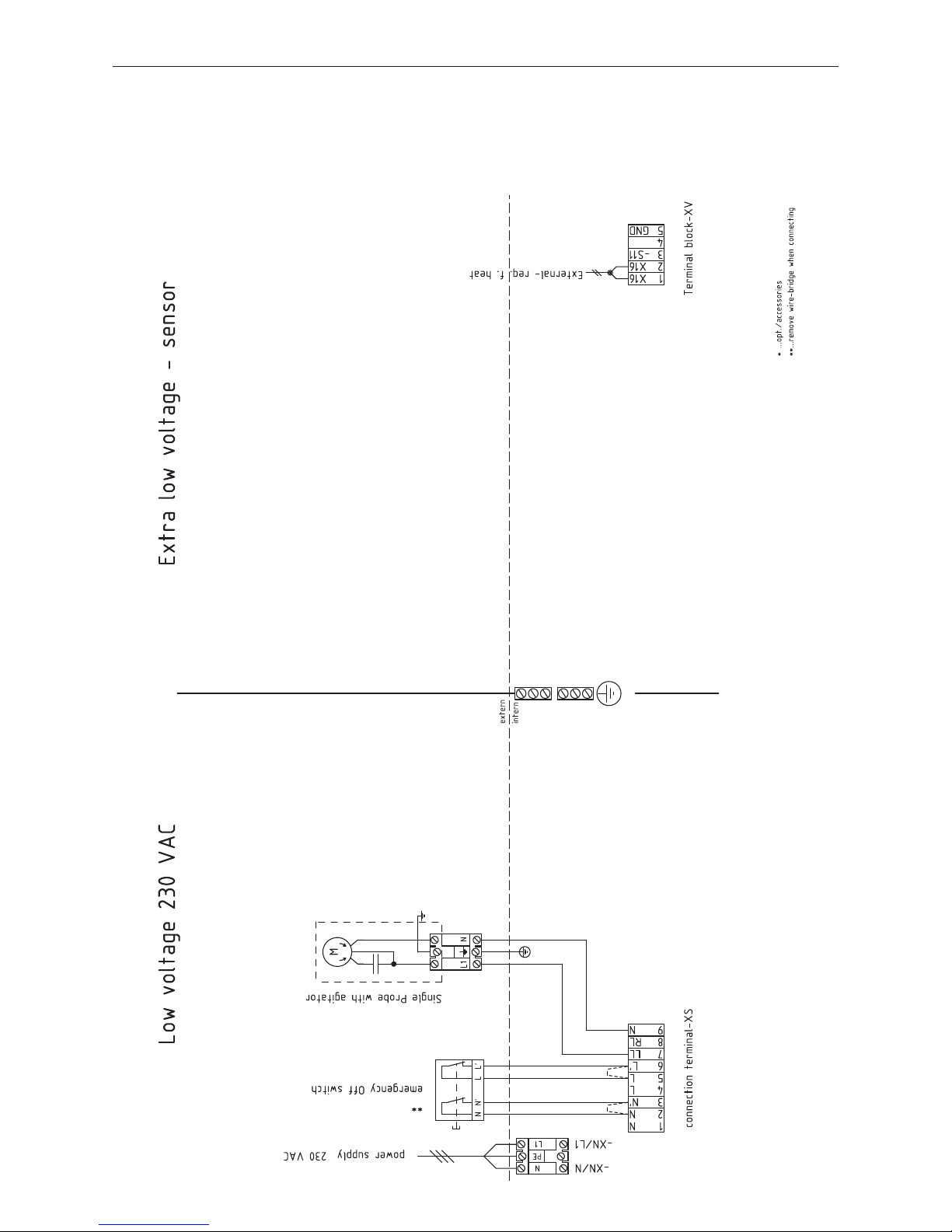
4.11 Circuit diagram for BioWIN 100–260 pellet feed with
solo probe
Operation with a „solo probe“ must be set in the service level – see section 4.6.1 Parameters; type of pellet feed
system.
093276/00
Page 42
42
4. For the Service Technician
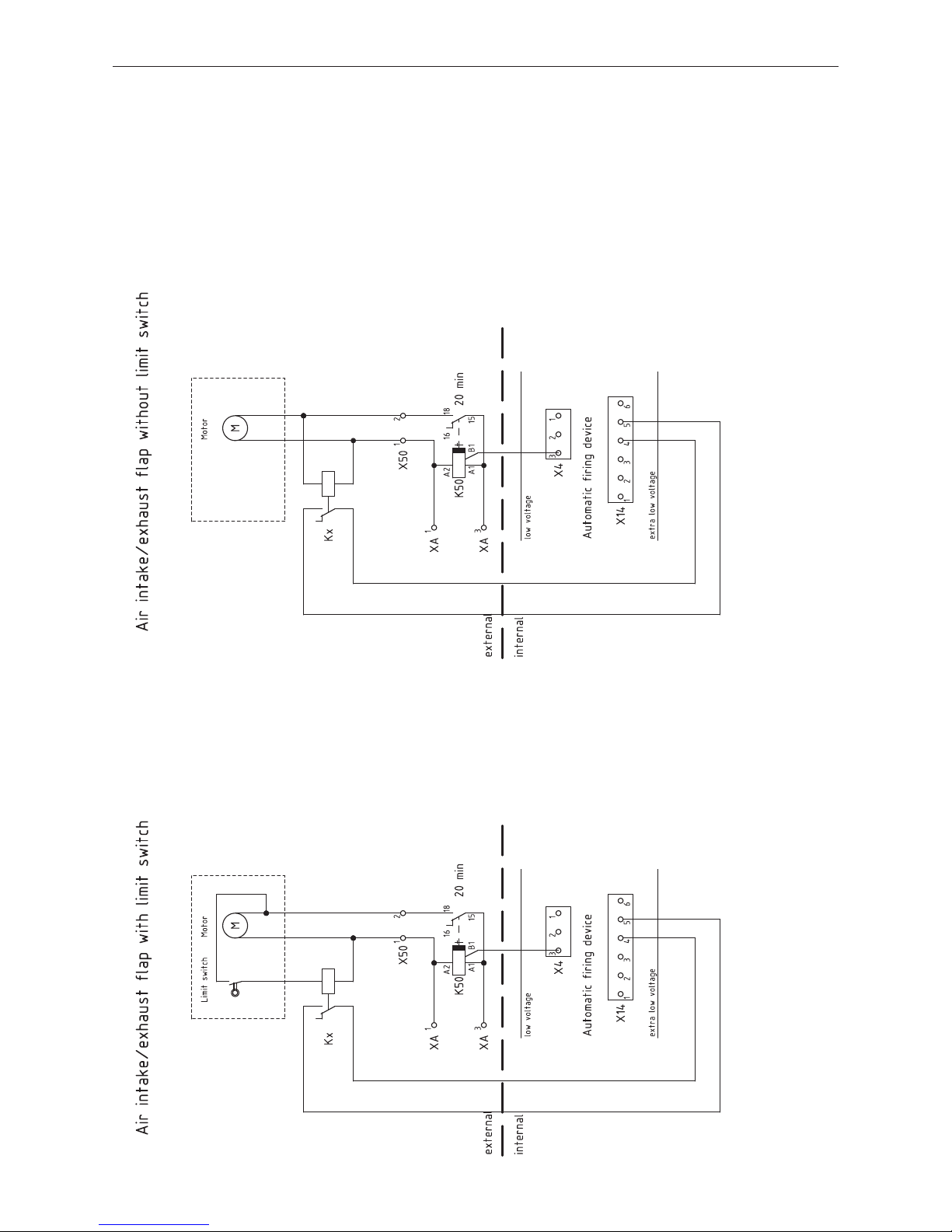
4.12 Connecting diagram for air intake/exhaust flap
The air intake/exhaust flap is directly connected to the automatic firing device (see basic circuit diagram 4.8) at
plug X4 (motor) and X14 (limit switch).
To set parameters for air intake/ exhaust flap, see section 4.6.1 Parameters; Flue gas thermostat or Air intake/
exhaust flap.
093182/01
Page 43
43
4. For the Service Technician
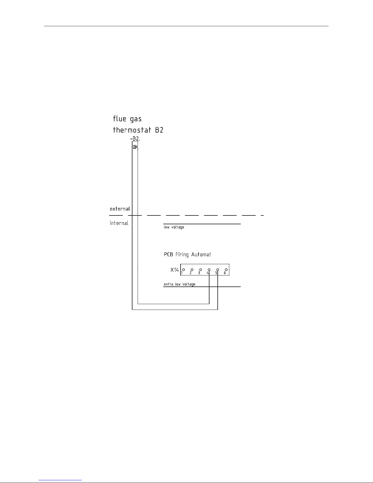
093311/00
4.13 Connecting diagram for flue gas thermostat
The flue gas thermostat is directly connected to the automatic firing device (see basic circuit diagram 4.8) at plug
X4 (motor) and X14 (limit switch).
To set parameters for flue gas thermostat, see section 4.6.1 Parameters; Flue gas thermostat or Air intake/ exhaust flap.
Page 44

Austria
Windhager Zentralheizung GmbH
A-5201 Seekirchen bei Salzburg
Anton-Windhager-Str. 20
Tel. +43 (0) 62 12/23 41-0
Fax +43 (0) 62 12/42 28
E-mail: [email protected]
Germany
Windhager Zentralheizung GmbH
D-86405 Meitingen bei Augsburg
Deutzring 2
Tel. +49 (0) 82 71/80 56-0
Fax +49 (0) 82 71/80 56-30
E-mail: [email protected]
Switzerland
Windhager Zentralheizung Schweiz AG
CH-6203 Sempach-Station bei Luzern
Industriestrasse 13
Tel. +41 (0) 41/46 94 69-0
Fax +41 (0) 41/46 94 69-9
E-mail: [email protected]
France
Windhager Chauffage Central SAS
1, rue du Maire Georges Baruch
Z.A.C. Nord du Rosenmeer
F-67560 Rosheim
Tel. +33 (0) 3 88 81 82 17
Fax +33 (0) 3 88 95 81 85
E-mail: [email protected]
GUARANTEE AND WARRANTY LIMITATIONS
The guarantee and warranty limitations require that the boiler and related
accessories be properly installed and started up by Windhager Customer Service
or Customer Service Partner; otherwise the manufacturer’s guarantee will not be
honoured.
Malfunctions resulting from improper operation or adjustment as well as use
of poor or not recommended fuel types are not covered by the guarantee and
warranty. Further, the warranty shall be void if equipment other than those provided
by Windhage are installed. The special warranty restrictions for your system are
available in the “Warranty Conditions” folder supplied with your boiler.
Start-up and regular maintenance following the terms of the “Warranty Conditions”
will assure safe, environmentally friendly and economical operation of your system.
We recommend that you obtain a maintenance service contract.
Subject to technical modifications. AWP-vor--übersetzt aus 023716/12
 Loading...