

Page 1
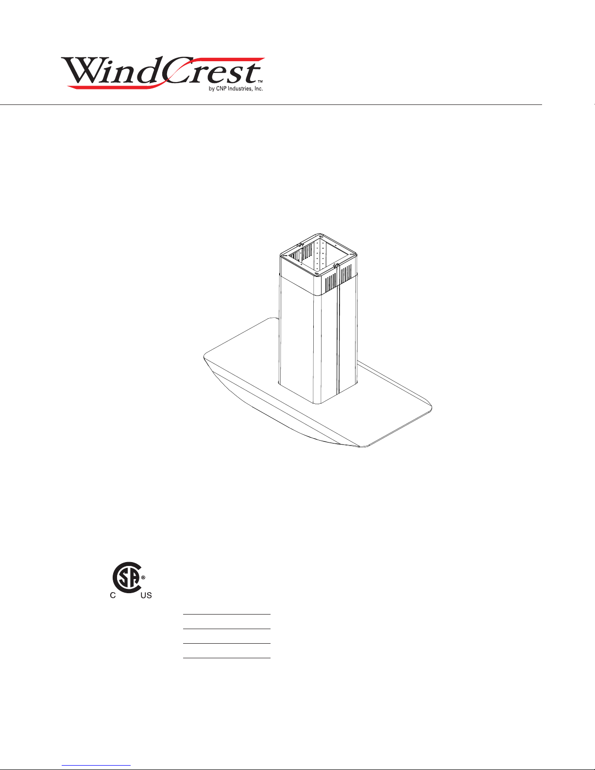
PCG36S
PCG42S
www.windcrestcnp.com
Model number:
Serial Number:
Date of Purchase:
Sales Dealer:
MAR12.0401
Copyright © 2011 CNP Industries, Inc.
Use, Care, and Installation Guide
READ AND SAVE THESE INSTRUCTIONS
Page 2

www.windcrestcnp.com
Page 3

SAFETY NOTICE ................................................................. 2-3
LIST OF MATERIALS ....................................................... 4
INSTALLATION
Ducting Calculation Sheet
....................................... 5
Mounting Height & Clearance
Ducting Options
Hood Specifi cations
Mounting the Hood
........................................................... 7
................................................... 8
..................................................... 9-12
FEATURES & CONTROLS
Touch Controls
............................................................. 13
Charcoal Filter Change Reminder
Mesh Filter Clean Reminder
.................................. 15
MAINTENANCE
Hood and Filter Cleaning
Lights
................................................................................ 17
TROUBLESHOOTING
WIRING DIAGRAMS
................................................................ 18
................................................................... 19
......................................... 16
LIST OF PARTS AND ACCESSORIES
................................ 6
Table of Contents
....................... 14
.............................. 20
1
Page 4

READ AND SAVE THESE INSTRUCTIONS
www.windcrestcnp.com
WARNING
TO REDUCE THE RISK OF FIRE OR ELECTRIC SHOCK, DO NOT USE THIS FAN WITH ANY SOLID-STATE CONTROL DEVICE.
WARNING
TO REDUCE THE RISK OF FIRE ELECTRIC SHOCK, OR INJURY TO PERSONS, OBSERVE THE FOLLOWING:
a. Use this unit only in the manner intended by the manufacturer, if you have questions, contact the manufacturer.
b. Before servicing or cleaning unit, switch power off at service panel and lock panel to prevent power from being switched on accidentally.
When the service disconnecting means cannot be locked, securely fasten a prominent warning device, such as a tag, to the service
panel.
CAUTION
For general ventilating use only. Do not use to exhaust hazardous or explosive materials and vapors. Take care when using cleaning
agents or detergents. Suitable for use in household cooking area.
WARNING
TO REDUCE THE RISK OF RANGE TOP GREASE FIRE:
a. Never leave surface units unattended at high settings. Boilovers cause smoking and greasy spillovers that may ignite. Heat oils slowly
on low or medium settings.
b. Always turn hood ON when cooking at high heat or when fl aming food
c. Clean ventilating fans frequently. Grease should not be allowed to accumulate on fan or fi lter.
Important Safety Notice
d. Use proper pan size. Always use cookware appropriate for the size of the surface element.
e. Keep fan, fi lters and grease laden surfaces clean.
f. Use high setting on hood only when necessary.
g. Don’t leave hood unattended when cooking.
h. Always use cookware and utensils appropriate for the type of and amount of food being prepared.
WARNING
TO REDUCE THE RISK OF INJURY TO PERSONS IN THE EVENT OF A RANGE TOP FIRE, OBSERVE THE FOLLOWING:
a. SMOTHER FLAMES with a close-fi tting lid, cookie sheet, or metal tray, then turn off the burner. BE CAREFUL TO PREVENT BURNS.
If the fl ames do not go out immediately, EVACUATE AND CALL THE FIRE DEPARTMENT.
b. NEVER PICK UP A FLAMING PAN – You may be burned.
c. DO NOT USE WATER, including wet dishcloths or towels – a violent steam explosion will result.
d. Use an extinguisher ONLY if:
1. You know you have a Class ABC extinguisher, and you already know how to operate it.
2. The fi re is small and contained in the area where it started.
3. The fi re department is being called.
4. You can fi ght the fi re with your back to an exit
WARNING
TO REDUCE THE RISK OF FIRE, ELECTRIC SHOCK OR INJURY TO PERSONS, OBSERVE THE FOLLOWING:
a. Installation work and electrical wiring must be done by qualifi ed person(s) in accordance with all applicable codes and standards.
Including fi re-rated construction.
b. Suffi cient air is needed for power combustion and exhausting of gases through the fl ue (chimney) of fuel burning equipment to prevent
back-drafting. Follow the heating equipment manufacturer’s guideline and safety standards such as those published by the National
Fire Protection Association (NFPA) and the American Society for Heating, Refrigeration and Air Conditioning Engineers (ASHRAE) and
the local code authorities.
c. When cutting or drilling into wall or ceiling, do not damage electrical wiring and other hidden utilities.
d. Ducted fans must always vent to the outdoors.
e. If this unit is to be installed over a tub or shower, it must be marked as appropriate for the application and be connected to a GFI
(Ground Fault Interrupter protected branch circuit).
g. NEVER place a switch where it can be reached from a tub or shower.
h. Make sure the power is off before installing, wiring or maintenancing.
2
Page 5

WARNING
TO REDUCE THE RISK OF FIRE, USE ONLY METAL DUCTWORK.
NOT FOR USE IN OUTDOOR COOKING ENVIRONMENTS.
CAUTION
To reduce risk of fi re and to properly exhaust air outside - Do not vent exhaust air into spaces within walls, ceilings,
attics, crawl spaces or garages.
OPERATION
Always leave safety grilles and fi lters in place. Without these components, operating blowers could catch onto hair, fi ngers
and loose clothing.
The manufacturer declines all responsibility in the event of failure to observe the instructions given here for installation,
maintenance and suitable use of the product. The manufacturer further declines all responsibility for injury due to
negligence and the warranty of the unit automatically expires due to improper maintenance.
*NOTE: Please check www.windcrestcnp.com for revisions before doing any custom work.
ELECTRICAL REQUIREMENTS
Important:
Observe all governing codes and ordinances.
It is the customer’s responsibility:
- To contact a qualifi ed electrical installer.
- To assure that the electrical installation is adequate and in conformance with National Electrical Code, ANSI/NFPA 70
latest edition* or CSA standards C22.1-94, Canadian Electrical Code, Part 1 and C22.2 No.0-M91 - latest edition** and
all local codes and ordinances.
If codes permit and a separate ground wire is used, it is recommended that a qualifi ed electrician determine that the
ground path is adequate.
Do not ground to a gas pipe.
Check with a qualifi ed electrician if you are not sure the range hood is properly grounded.
Do not have a fuse in the neutral or ground circuit.
*National Fire Protection Association Batterymarch Park, Quincy, Massachusetts 02269
** CSA International 8501 East Pleasant Valley Road, Cleveland, Ohio 44131-5575
This appliance requires a 120V 60Hz electrical supply and connected to an individual properly grounded branch circuit
protected by a 15 or 20 ampere circuit breaker or time delay fuse. Wiring must be 2 wire with ground. Please also refer to
Electrical Diagram on product.
A cable locking connector (not supplied) might also be required by local codes. Check with local requirements, purchase
and install appropriate connector if necessary.
PCG36S & PCG42S - MAX 400 Watts, 3.3 Amps
Important Safety Notice
3
Page 6
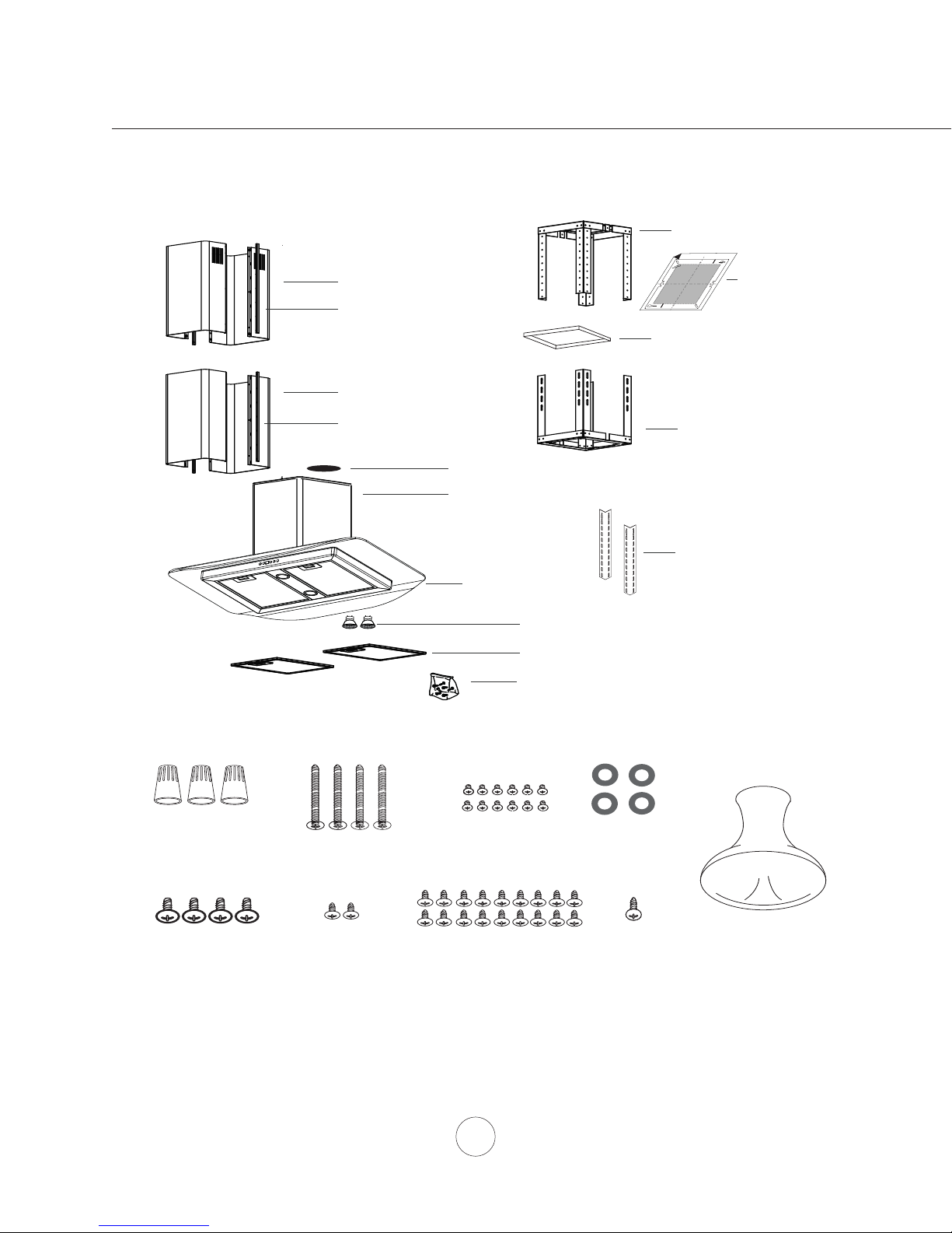
MODELS: PCG36S & PCG42S
PARTS SUPPLIED
2 - Top duct covers
2 - Thick trim pieces
www.windcrestcnp.com
1 - Top support frame
Front of Hood
C
/
L
B
Cut-Out Shaded Area
1 - Paper ceiling
A
1 - Square support frame bracket
template
List of Materials
HARDWARE PACKAGE CONTENTS
(3) Wire Nuts
(4)
M6 x 1-1/2”
(wood screws)
2 - Bottom duct covers
2 - Thin trim pieces
1 - 6” round damper (pre-installed)
1 - Hood body w/ blower (pre-installed)
(duct cover screws)
1 - Canopy, glass
2 - 50W GU-10 halogen lights
2 - Stainless steel mesh filters
1 - Hardware package
(12) M3 x 6
(4) 5 x 12
1 - Bottom support frame
2 - Lateral support brackets
(1) Suction Cup
(4) 3/16 x 8
(canopy screws)
(2) M4 x 8
(top support
frame screws)
PARTS NOT SUPPLIED
- Ducting, conduit and all installation tools
- Cable connector (if required by local codes)
- Duct cover extension accessory
- Recirculating kit accessory
(18) M4 x 8
(sheet metal screws)
4
(1) M4 x 12
(safety screw)
Page 7
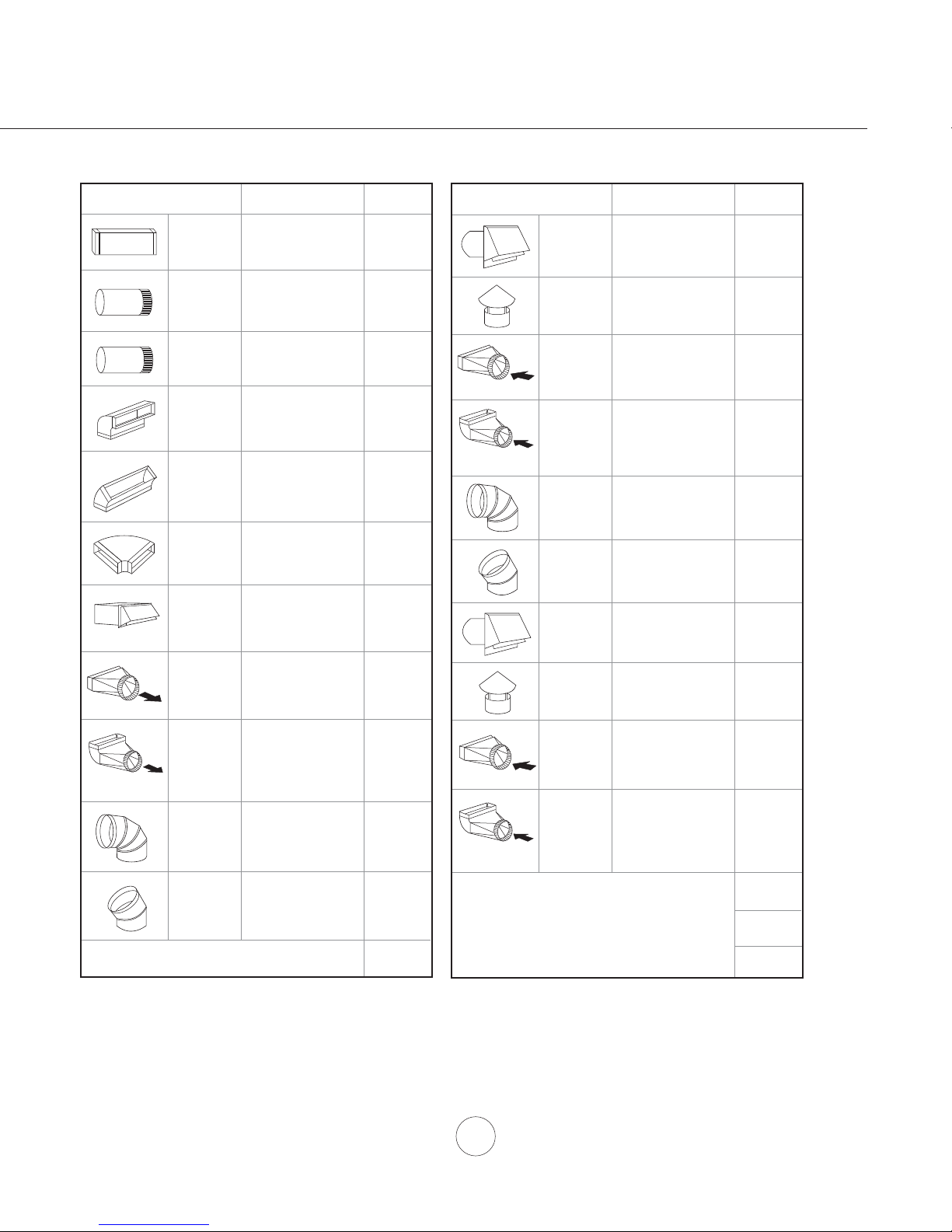
Duct pieces
3- 1/ 4” x 10”
Rect.,
straight
Equivalent number
length x used =
1 Ft. x ( ) =
To t a l
Ft.
Duct pieces
6”- 8” Round
wall cap
with damper
Equivalent number
length x used =
30 Ft. x ( ) =
To t a l
Ft.
7” Round,
straight
8” Round,
straight
3- 1/ 4” x 10”
0
Rect. 90
elbow
3- 1/ 4” x 10”
0
Rect. 45
elbow
3- 1/ 4” x 10”
0
Rect. 90
flat elbow
3- 1/ 4” x 10”
Rect.
wall cap
with damper
3- 1/ 4” x 10”
Rect. to
6” round
transition
3- 1/ 4” x 10”
Rect. to
6” round
transition
0
elbow
90
6” Round,
0
elbow
90
1 Ft. x ( ) =
1 Ft. x ( ) =
15 Ft. x ( ) =
9 Ft. x ( ) =
24 Ft. x ( ) =
30 Ft. x ( ) =
5 Ft. x ( ) =
20 Ft. x ( ) =
15 Ft. x ( ) =
Ft.
Ft.
Ft.
Ft.
Ft.
Ft.
Ft.
Ft.
Ft.
6”- 8” Round,
roof cap
6” round to
3- 1/ 4” x 10”
rect.
transition
6” round to
3- 1/ 4” x 10”
rect.
transition
0
elbow
90
7” or 8”
Round,
0
90
elbow
7” or 8”
Round,
0
45
elbow
7” or 8”
Round
wall cap
with damper
7” or 8”
Round,
roof cap
7” round to
3 1/ 4” x 10”
rect.
transition
7” round to
3- 1/ 4” x 10”
rect.
transition
0
elbow
90
30 Ft. x ( ) =
1 Ft. x ( ) =
16 Ft. x ( ) =
15 Ft. x ( ) =
9 Ft. x ( ) =
30 Ft. x ( ) =
30 Ft. x ( ) =
8 Ft. x ( ) =
23 Ft. x ( ) =
Ft.
Ft.
Ft.
Ft.
Ft.
Ft.
Ft.
Ft.
Installation – Ducting Calculation Sheet
Ft.
6” Round,
0
elbow
45
9 Ft. x ( ) =
Subtotal column 1 =
Maximum Duct Length: For satisfactory air movement,
the total duct length of a 3 1/ 4” x 10” rectangular 6” or 7”
diameter round duct should not exceed 100 equivalent feet.
Ft.
Ft.
Subtotal column 2 =
Subtotal column 1 =
Total ductwork =
Ft.
Ft.
Ft.
5
Page 8
www.windcrestcnp.com
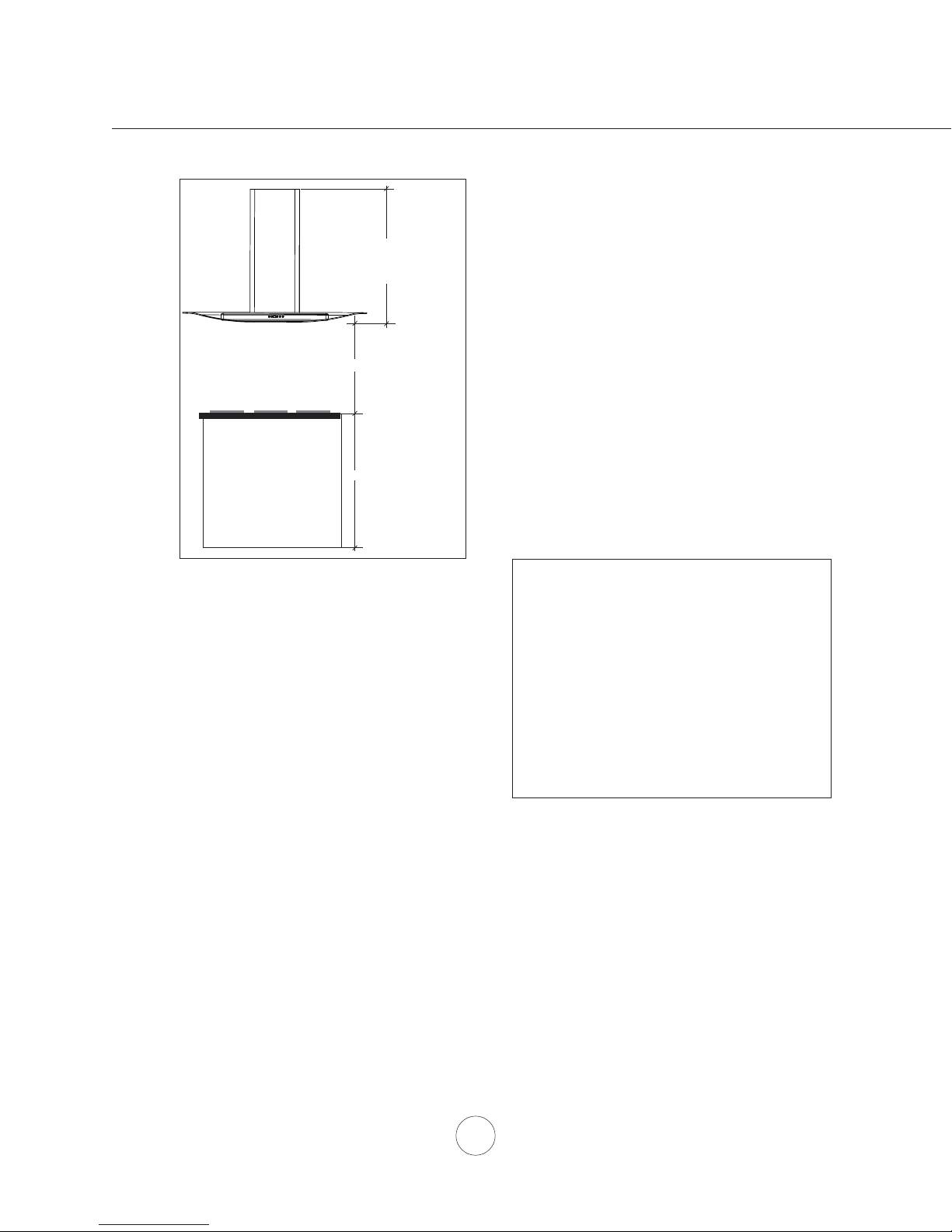
Minimum mount height between range top to hood
bottom should be no less than 26”.
Min. ducted 28”
Min. recirc. 32 ”
Max. 50”
Min 26"-Max 34"
36"
DUCTING
A minimum of 6” round duct must be used to
maintain maximum air fl ow effi ciency.
Always use rigid type metal ducts only. Flexible
ducts could restrict air fl ow by up to 50%.
Use calculation worksheet to compute total duct
work (Page 5).
Installation – Mounting Height & Clearance
ALWAYS, when possible, reduce the number of
transitions and turns. If a long duct run is required,
increase duct size from 6” to 7” or 8”.
Maximum mount height should be no higher than
34”.
It is important to install the hood at the proper
mounting height. Hoods mounted too low could
result in heat damage and fi re hazard; while hoods
mounted too high will be hard to reach and will
loose its performance and effi ciency.
If available, also refer to range manufacturer’s
height clearance requirements and recommended
hood mounting height above range. Always check
your local codes for any differences.
Duct cover extension kit available for ceiling heights
up to 12 feet. Turn to page 20 for part number and
ordering information.
DAMAGE-SHIPMENT / INSTALLATION:
• Please fully inspect unit for damage before
• If the unit is damaged in shipment, return the
• If the unit is damaged by the customer, repair
• If the unit is damaged by the installer (if other
installation.
unit to the store in which it was bought for
repair or replacement.
or replacement is the responsibility of the
customer.
than the customer), repair of replacement must
be made by arrangement between customer
and installer.
If turns or transitions are required: Install as far
away from duct opening and as far apart between
the two transitions as possible.
6
Page 9
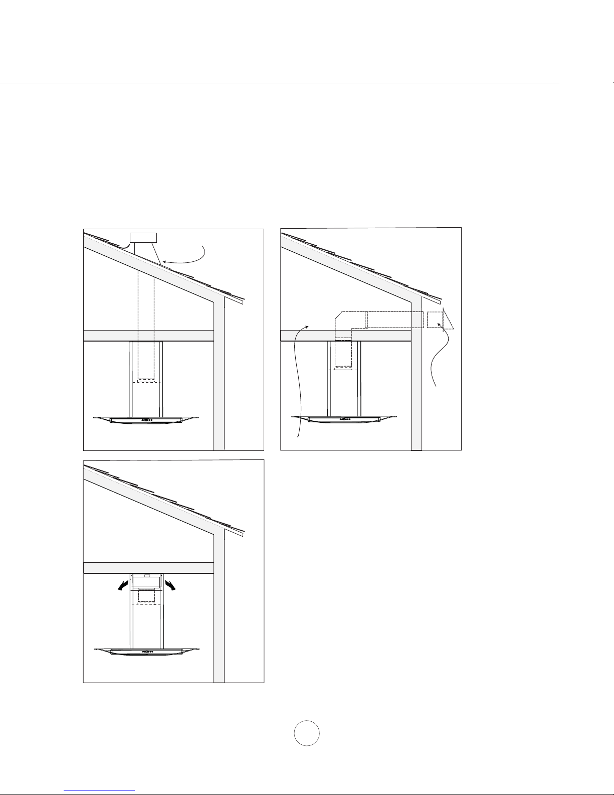
WARNING FIRE HAZARD
NEVER exhaust air or terminate duct work into spaces between walls, crawl spaces, ceiling, attics or garages.
All exhaust must be ducted to the outside, unless using the recirculating option.
Ductless or recirculating installations require an accessory kit. Turn to page 20 for part number and ordering
information.
Use single wall rigid Metal ductwork only.
Fasten all connections with sheet metal screws and tape all joints w/certifi ed Silver Tape or Duct Tape.
Some Ducting Options
Roof Pitch w/
Flashing & Cap
(blower
housing)
(blower
housing)
ductless
recirculating
(blower
housing)
Soffit or crawl space
side wall cap
w/ gravity damper
Installation – Ducting Options
7
Page 10
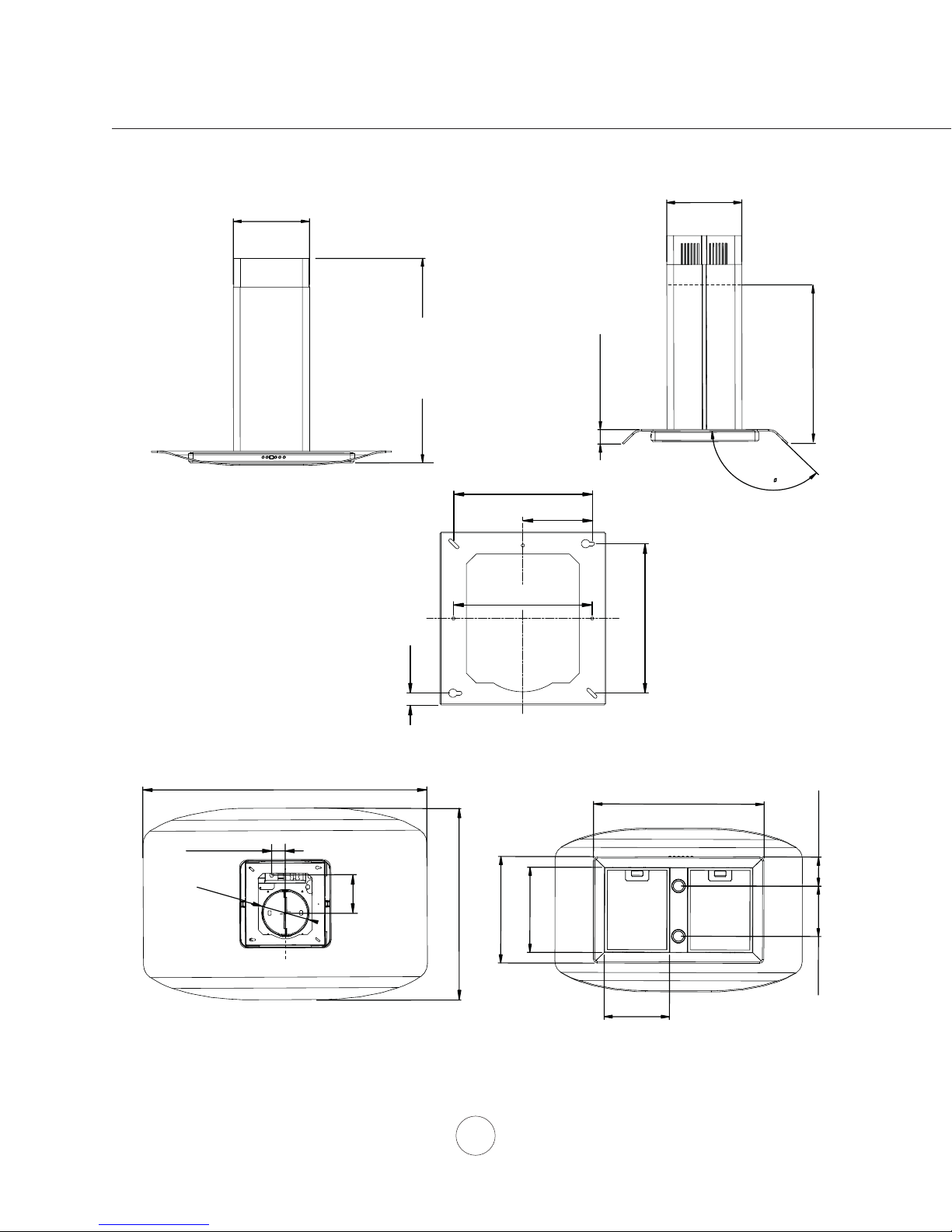
11-1/4”
www.windcrestcnp.com
11”
Min. Ducted - 28”
Min. Recirc. - 32”
Installation – Hood Specifi cations
Maximum - 50”
2-3/16”
8-1/4”
FRONT SIDE
4-1/8”
8-1/4”
C/L
3/4”
9”
TOP SUPPORT FRAME
(top view)
35-7/16” or 42”
24-7/16”
23-1/16”
(top of electrical box)
135
1-11/16”
6”
C/L
TOP of HOOD
4-13/16”
24-1/4”
8
12-5/8”
15-3/4”
4-5/16”
7-1/2”
9-3/8”
Bottom of HOOD
Page 11
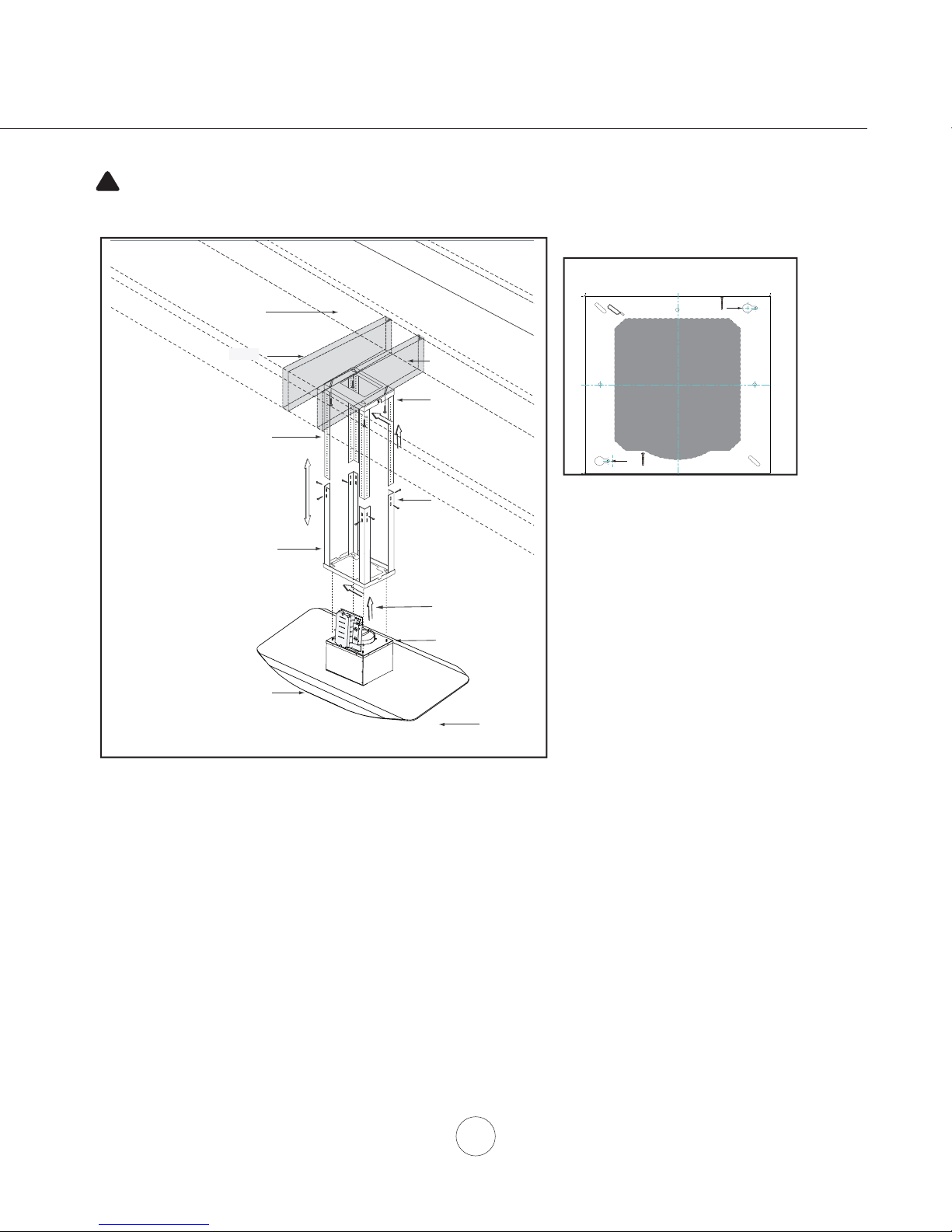
WARNING: Electrical wiring must be done by a qualified person(s) in
!
accordance with all applicable codes and standards. This range hood must be
properly grounded. Turn off electrical power at service entrance before wiring.
Ceiling Joists
PAPER TEMPLATE
Front of Hood
C/L
B
Cut-Out Shaded Area
Wood Blocking
Top Support Frame
Bottom Support Frame
Hood Body/Canopy
front
FIG. A
1
3
A
FIG. B
2
6
5
4
Installation – Mounting the Hood
Hood is intended to be mounted to a fi nished ceiling.
1. Ceiling Preparation: Determine hood mounting location and temporarily tape paper template (included with the
hood) to the ceiling. Cut-out internal shaded area of template to allow the ducting and electrical to pass through
(approx. 7”W x 7(FIG. A, #1) Secure (2) 1tighten screws, leave approx. 1/4” exposed.
2. Hood Preparation: Remove screws securing top and bottom support frames together. Adjust support frame to
accommodate the desired hood height and re-assemble the frame using the previously removed screws (2 screws
for each support frame arm). (FIG. A, #2)
1/2”D). Add wood blocking (min. 2” x 4”) onto ceiling joists to refi nforce ceiling above the drywall.
1/2” wood screws into points A and B of the paper template (FIG. B). Do not completely
9
Page 12
www.windcrestcnp.com
FIG. C
FRONT
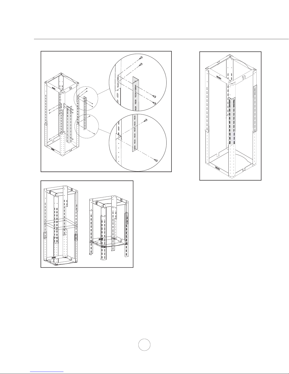
Installation – Mounting the Hood
1
FIG. E
5. Lift support frame assembly up to the ceiling making sure the the word “front” on the top support frame faces the
front of the hood where the controls will be located (FIG. D). The key-holes on the top support frame should cover
the wood screws previously installed in the ceiling. Slide support frame towards narrow end of key-holes to lock
the frame in place.
6. Install the last (2) 1-1/2” wood screws with washers into the two remaining corners of the top support frame to
secure it to the ceiling. Tighten all screws.
FRONT
3. The support frame has cut off arms to allow for swinging the
lower grid into position with the upper grid. Once the grids are
set into position, add the lateral support brackets to the two
top support frame cut off arms and their corresponding bottom
support frame arms. Secure lateral support brackets using (12)
M4 x 8 sheet metal screws (FIG. C).
2
4. For added stability, taller hood heights will also require the
square support bracket to be installed inside the support frame.
Install square support bracket to top support frame arms using
(8) M4 x 8 sheet metal screws. (FIG. E, #1) Top support frame
arms extend past lower support frame bracket with shorter hood
heights. (FIG. E, #2)
FIG. D
10
Page 13
!
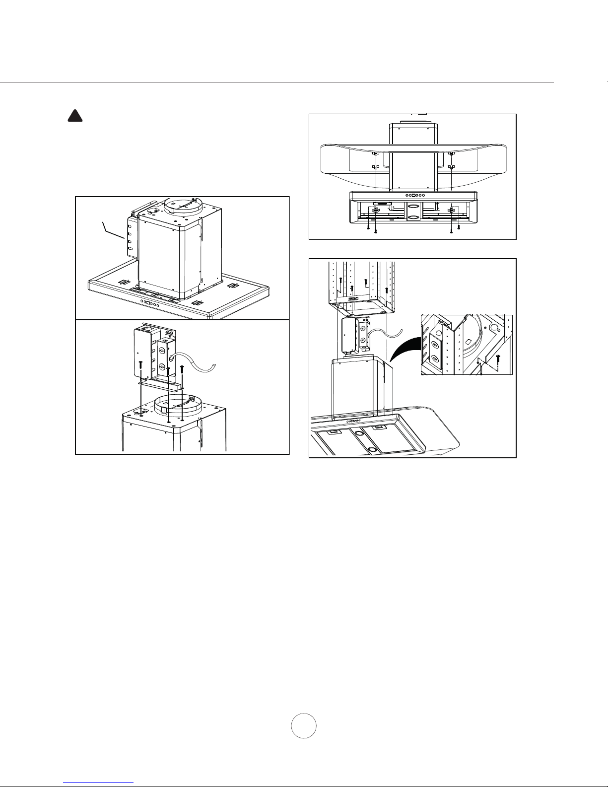
CAUTION: At least two installers are
required due to the weight and size of the
hood.
ELECTRONICS
MOUNTING
BRACKET
FIG. G
1
1
2
Installation – Mounting the Hood
FIG. F
7. Remove tape securing electronics mounting bracket to hood. (FIG. F, #1) Remove (3) screws from top of hood
body and set screws aside. Position electronics mounting bracket as show in (FIG. F, #2) and secure to hood body
using the (3) previously removed screws.
8. Remove stainless steel mesh filters from hood. Place canopy over blower housing located on top of hood and
secure it to hood body using (4) 3/16” x 8 screws. (FIG. G)
9. Lift hood body and align the (4) pre-installed mounting screws on top of blower housing (FIG. A, #5 on Page 9) with
the (4) key holes on the bottom of the support frame. (FIG. H) Slide hood towards the narrow end of key holes to lock
in place. Hand tighten each of the (4) screws to secure hood to bottom of support frame. Install (1) 4mm x 12mm long
safety screw into bottom support frame to further secure the hood. (FIG. H, #1) Reinstall mesh fi lters.
10. Install electrical and duct work. Seal duct work with aluminum duct tape.
11. Power up hood, verify all functions and check for leaks around duct tape.
FIG. H
11
Page 14
www.windcrestcnp.com
cut trim piece
if necessary
Top support frame
Top duct covers
Bottom duct covers
Installation – Mounting the Hood
Bottom support frame
1
2
Thick trim piece (top)
5
4
Thin trim piece (bottom)
3
FIG. J
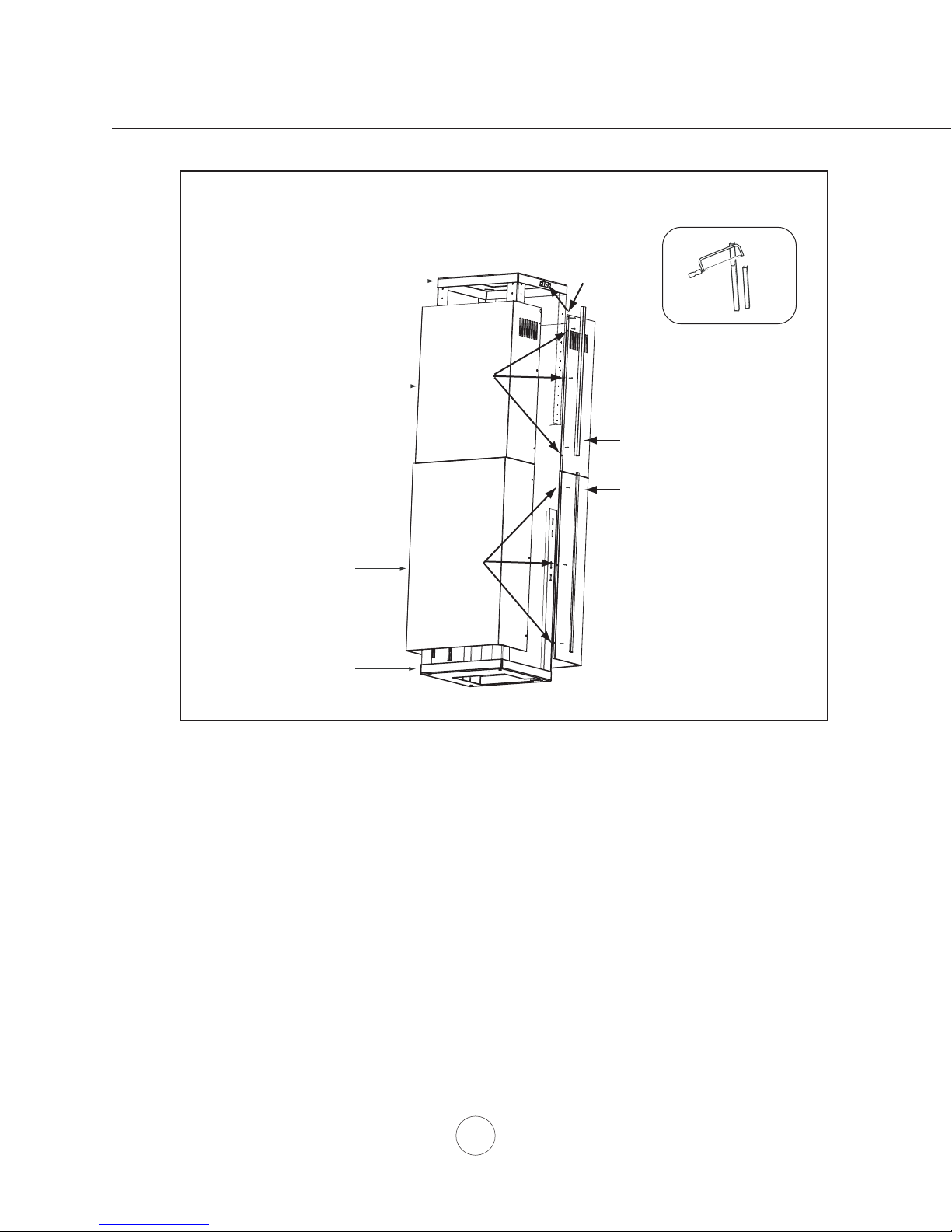
12. *Secure top duct covers (with louver holes) to top support frame using (2) M4 x 8 screws. (FIG. J, #1). Note: If using
hood in “ducted mode” the top duct covers may be turned upside-down to hide the louver holes.
13. Assemble top duct covers together using (3) M3 x 6 screws on each side. (FIG. J, #2). Larger screw hole openings
should overlap the smaller holes.
14. Assemble bottom duct covers together over top duct covers using (3) M3 x 6 screws on each side. Bottom duct
covers will rest on top of the hood body. (FIG. J, #3)
15. Insert the (2) thin trim pieces into left and right seams of bottom duct covers. (1 on each side)
(FIG. J, #4)
16. Insert the (2) thick trim pieces into left and right seams of top duct covers. (1 on each side) (FIG. J, #5) Note:
Because less of the top duct covers will be exposed, it may be necessary to measure and cut the thick trim
pieces before installing them into the top duct covers.
* If using hood in recirculating mode you must install the air diverter plate before assembling the duct covers.
Please refer to recirculating kit manual for further details.
12
Page 15
Blower On/Off
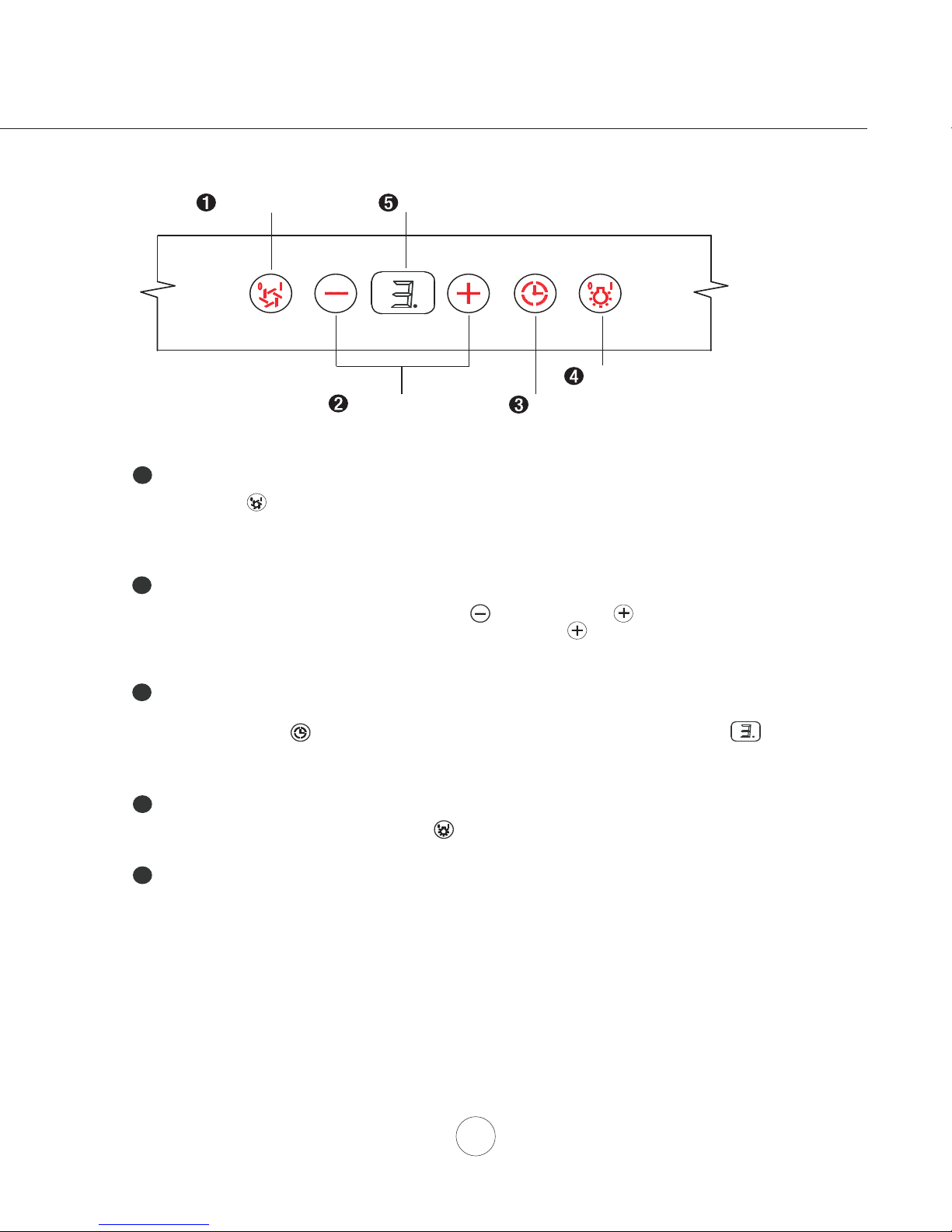
By pressing , the blower is switched On and Off. When switched On, the blower will
operate at the last setting before it was switched Off. When switched Off the entire hood
powers Off, including the lights.
Speed Selection
The 3 speed levels are selected by pressing to decrease and to increase speed
level. The display indicates speed level selected. Pressing when the hood is Off will
also switch the blower On.
Delay Off
Delay Off is used for programmed shut down of blower and lights 15 minutes after the function
is activated. Press once and a dot will appear in the lower right side of the Display
indicating the function is on. The hood will change to Speed 1 and shut down after 15 minutes.
Lights Normal/Dim/Off
Switch lights on to Normal by pressing once, again to Dim and again to switch Off.
1
2
3
4
Display
Displays blower speed level, delay off status, mesh filter clean and charcoal filter replace notification.
5
Lights Normal/Dim/Off
15 Min Delay Off
Display (speed level, delay of
f, filter clean/replace)
Speed Selection
Blower On/Off
Features & Controls - Touch Controls
13
Page 16
www.windcrestcnp.com
Charcoal Filter Change Reminder (charcoal filter, if installed)
When your hood is installed as a recirculating unit, it is fitted with a set of charcoal filters to purify exhaust
and fumes from cooking, then re-circulates the air within the home. These charcoal filters are required to
be replaced after every 120 hours of use. The charcoal filters should never be cleaned or placed in a dish
washer.
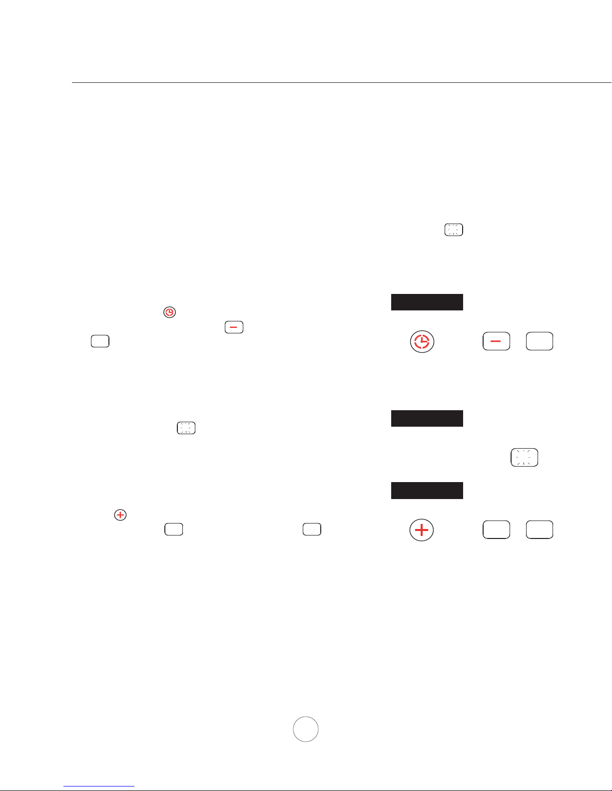
The filter change reminder function in the microprocessor needs to be switched on. When switched on, the
microprocessor will elapse and count usage time and indicate by a flashing when charcoal filter
replacements are needed.
C
Setting the Filter Change Reminder
When off, hold for approximately 5 seconds.
The display will change from (exhaust mode) to
(recirculating mode) this indicates that the
elapse timer function is switched on and charcoal
filters are used.
Filter Replace Indicator
When the display starts flashing, the charcoal
filters need to be replaced.
Re-setting Function
Once filters are replaced, with hood off, press and
hold the display will appear; hold for apprimately
5 seconds until on displays disappears .
The filter change reminder is now re-set and a new
120 hour elapse cycle is initiated.
C
C
C
C
hold 5 sec. display from < - > to < C >
Set Mode
Set Mode
display < C > flashes
Change FIlters
C
hold 5 sec. display from < C > to < >
To Reset
C
Features & Controls - Charcoal Filter Change Reminder
14
Page 17
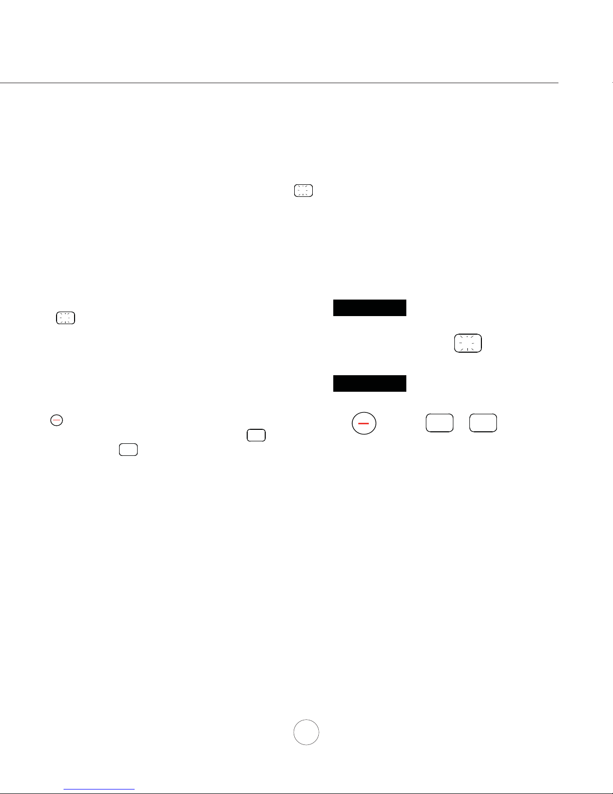
Metal Filter Clean Reminder (metal mesh filter)
Whether your hood is installed as an exhaust or purifying unit, a set if metal mesh filters are fitted by the
factory, These metal mesh filters are intended to filter out residue from cooking. They need not be
replaced on a regular basis but are required to be kept clean. The filter clean reminder function in the
microprocessor will automatically indicate by a flashing when the metal mesh filters need to be
cleaned after every 30 hours of use. Filters can be cleaned by hand with non-abrasive soap or in a
dishwasher. Heavily soiled filters should also be soaked in grease cutting detergent prior to cleaning.
Metal Filter Clean Indicator
When flashes on display, the metal filters
installed are required to be cleaned. This will occur
after every 30 hours of use.
Re-setting Function
Reset the filter clean reminder timer when filters are
cleaned and re-installed (with hood off). Press and
hold for approximately 5 seconds, the display will
appear; hold for approximately 5 seconds until on
display disappears . The filter clean reminder
function is now reset and a new 30 hours elapse
cycle is initiated.
F
Clean Filters
display < F > flashes
F
hold 5 sec. display from < F > to < >
To R ese t
F
F
F
Features & Controls - Metal Mesh Filter Clean Reminder
15
Page 18
www.windcrestcnp.com
SURFACE MAINTENANCE:
Clean periodically with hot soapy water and clean cotton cloth. Do not use corrosive or abrasive detergent,
or steel wool/scouring pads which will scratch and damage surface.
For heavier soil use liquid degreaser.
After cleaning it is recommended that you use non-abrasive stainless steel polish/cleaners such as Stainless
Steel Magic®, to polish and buff the stainless luster and grain. Always scrub lightly, with clean cotton cloth,
and with the grain.
Do not use any product containing chlorine bleach. Do not use “orange” cleaners.
Stainless Steel Mesh Filters
The stainless steel mesh fi lters installed by the factory are intended to fi lter out residue and grease from
cooking. They need not be replaced on a regular basis but are required to be kept clean.
Remove and clean by hand or in dishwasher on low heat. Spray degreasing detergent and leave to soak if
heavily soiled.
Dry fi lters and re-install before using hood.
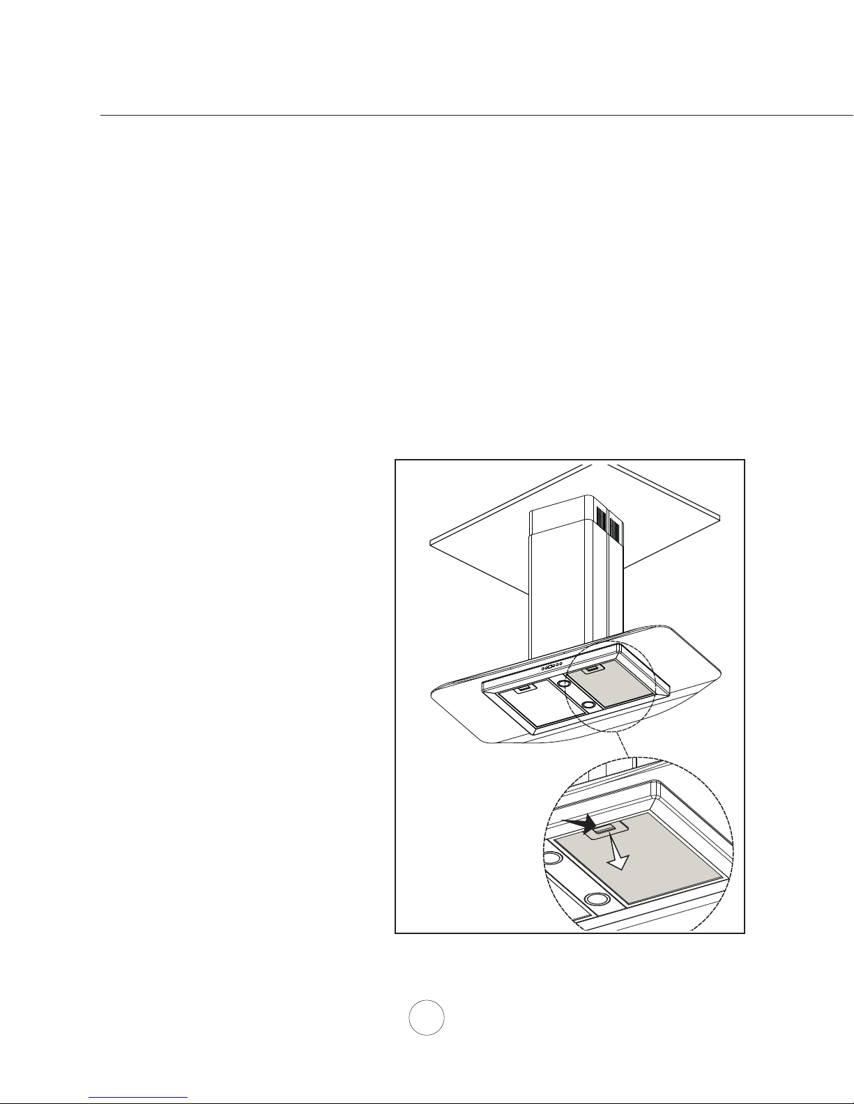
Removing Stainless Steel Mesh Filters
1. Push in on spring loaded handle
2. Pull down on fi lter hande to remove fi lter
Maintenance – Hood and Filter Cleaning
16
Page 19
REPLACING LIGHT BULBS
CAUTION: Light bulb becomes extremely hot when turned on.
DO NOT touch bulb until switched off and cooled. Touching hot bulbs could cause serious burns.
Make sure all power is turned off and bulbs are not hot.
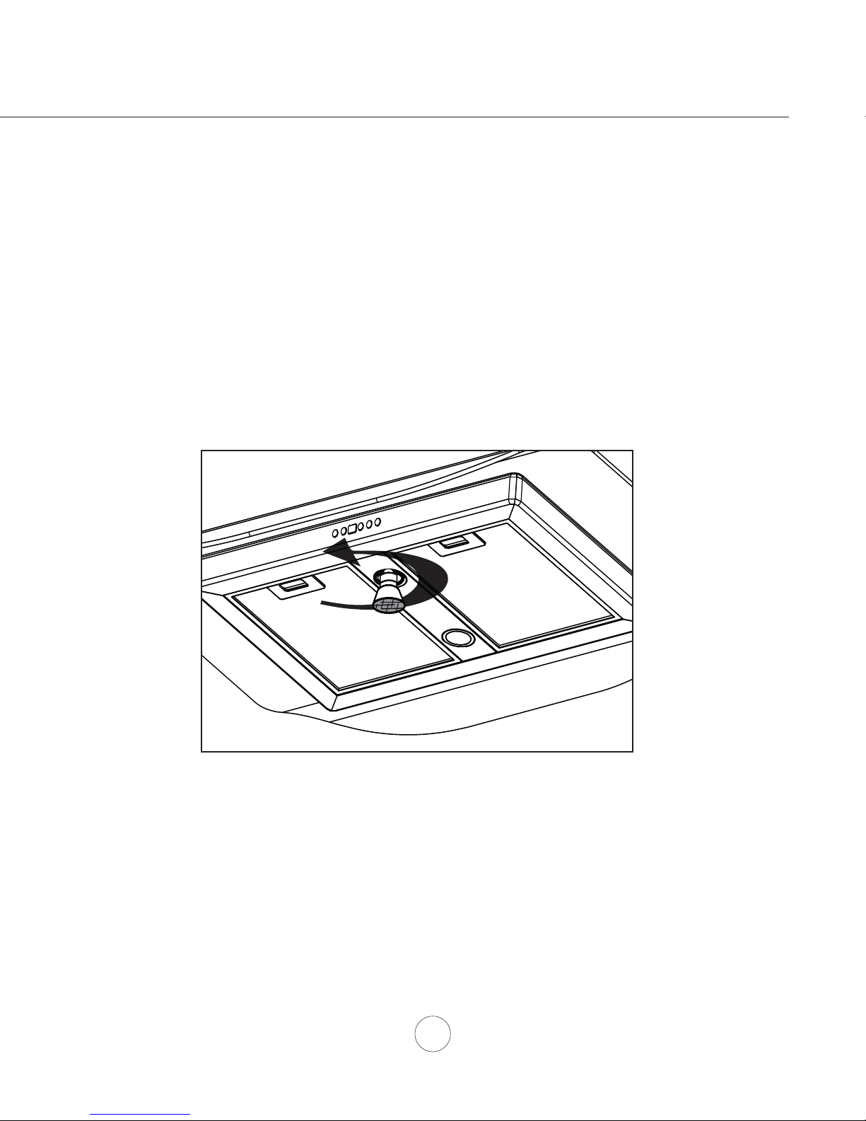
Remove by turning bulb counter clockwise. Note: Bulb does not unscrew; it turns 60 degrees,
stops and falls out.
If bulbs are diffi cult to turn due to prolonged use, fi rmly attach a glass suction cup (provided) or use a rubber/
latex glove and turn counter clockwise.
Replacement bulbs are available at specialty lighting stores. Purchase type GU-10 50W halogen.
For part numbers please turn to page 20 of the manual.
Maintenance – Lights
17
Page 20
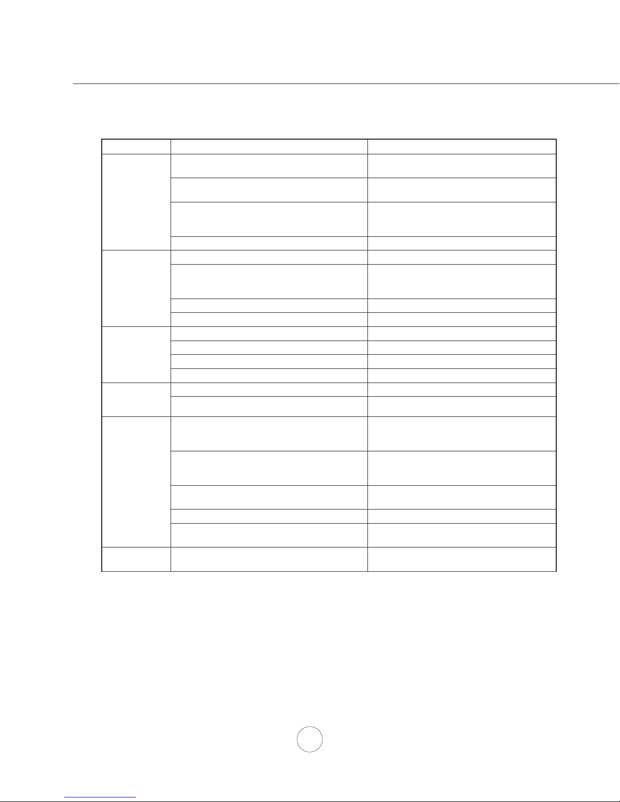
TROUBLESHOOTING PROCEDURES FOR PCG
Issue Cause What to do
After installation,
the unit doesn’t
work.
Troubleshooting
Light works,
but motor is not
turning.
The unit is
vibrating.
The motor is
working, but the
lights are not.
The hood is
not venting out
properly.
Mesh Filter is
vibrating.
1. The power source is not turned ON. 1. Make sure the circuit breaker and the unit’s
2. The power line and the cable locking connector
is not connecting properly.
3. The switch board and control board wirings are
disconnected.
4. The switch board or control board is defective. 4. Change the switch board or control board.
1. The motor is defective, possibly seized. 1. Change the motor.
2. The thermally protected system detects if the
motor is too hot to operate and shuts the motor
down.
3. Damaged capacitor. 3. Change the capacitor.
4. The switch board or control board is defective. 4. Change defective part.
1. The motor is not secure in place. 1. Tighten the motor in place.
2. Damaged blower wheel. 2. Replace the blower.
3. The hood is not secured in place. 3. Check the installation of the hood.
4. The switch board or control board is defective. 4. Change defective part.
1. Defective halogen bulb. 1. Change the halogen bulb.
2. The light bulb is loose. 2. Tighten the light bulb.
1. The hood might be hanging too high from the
cook top.
2. The wind from the opened windows or opened
doors in the surrounding area are affecting the
ventilation of the hood.
3. Blockage in the duct opening or ductwork. 3. Remove all the blocking from the duct work or
4. The direction of duct opening is against the wind. 4. Adjust the duct opening direction.
5. Using the wrong size of ducting. 5. Change the ducting to at least 6” or higher for
1. Mesh fi lter is loose. 1. Make sure the metal clips in the handle are
www.windcrestcnp.com
power is ON.
2. Check the power connection with the unit is
connected properly.
3. Make sure the wirings between the switch
board and control board are connected
properly.
2. The motor will function properly after the
thermally protected system cool down.
1. Adjust the distance between the cook top and
the bottom of the hood within 26” and 34”
range.
2. Close all the windows and doors to eliminate
the outside wind fl ow.
duct opening.
the internal blower.
not stuck. Or replace the mesh fi lter.
18
Page 21
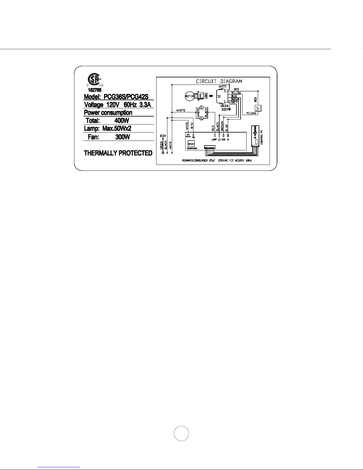
Wiring diagram label located through metal mesh fi lter opening on
under side of unit body.
Wiring Diagrams
19
Page 22

DESCRIPTION PART#
Replacement Parts
Light Bulb GU-10 50W (each) 11690.00
Metal Mesh Filter (each) 11692.00
Replacement Charcoal Filter (each) CF11688.00
Suction Cup S11557.00
www.windcrestcnp.com
List of Materials
Optional Accessories
Recirculating Kit RECKITPCG
Duct Cover Extension (up to 12’ ceiling) 12PCGEXT
To order parts, visit us online at www.windcrestcnp.com or call us at 1.877.387.6721
20
Page 23

www.wincrestcnp.com
TO OBTAIN SERVICE UNDER WARRANTY:
or any Service Related Questions, please call:
1-877-387-6721
TO OBTAIN SERVICE UNDER WARRANTY: You must present proof of original purchase date.
Please keep a copy of your dated proof of purchase (sales slip) in order to obtain service under warranty.
Staple your receipt here.
Proof of the original purchase
date is needed to obtain service
under the warranty.
FULL ONE YEAR WARRANTY
Covers repair and replacement of parts found to be defective due to material and workmanship for one year from date of
purchase.
SERVICE MUST BE PROVIDED BY A FACTORY AUTHORIZED SERVICE AGENCY, DURING NORMAL WORKING
HOURS.
ITEMS NOT COVERED IN WARRANTY
1.) Damage or repairs due to service by unauthorized agency or use of unauthorized parts.
2.) Service visits to teach you how to use the appliance.
3.) Correct installation related problems - you are responsible for providing electrical wiring and other connection items.
4.) Reset circuit breakers or replace fuses.
5.) Damage caused by abuse, accident, alteration, misuse and local code violations.
6.) Failure due to other than normal house use.
7.) Service to replace consumable parts (i.e. Light Bulbs, Heat Lamps, Filters).
8.) Expenses for travel and transportation if appliance is located in a remote area.
You may also write to us at:
Wind Crest™ by CNP Industries, Inc.
351 Thor Place
Brea, CA 92821
(877) 387-6721
This warranty applies to appliances used in residential applications only. The warranty is for products purchased and retained in the 50
states of the USA, the District of Columbia, and Canada. This warranty gives you specific legal rights. You may also have other rights,
which vary from state to state.
 Loading...