

Page 1
TH320
Quick Reference
Warranty Information
Wincor Nixdorf guarantees a limited warranty
engagement for 12 months beginning with the date of
delivery. This warranty engagement covers all those
damages which occur despite a normal use of the
product.
Damages because of
- improper or insufficient maintenance,
- improper use of the product or unauthorized
modifications of the product,
- inadequate location or surroundings
will not be covered by the warranty.
All parts of the product which are subject to wear and
tear are not included in the warranty engagement.
Connect only power supply units and cables approved
by Wincor Nixdorf.
Manufacturers Certificat i on
The device complies with the
requirements of the directive
2004/108/EC with regard to
‘Electromagnetic compatibil ity" and
RoHS directive 2011/65/EU.
Therefore, you will find the CE mark on the device or
packaging.
Tested Safety
The device has received the UL
and cUL approval.
FCC-Class A Declaration
This equipment has been tested and found to comply
with the limits for a Class A digital device, pursuant to
part 15 of the FCC Rules. These limits are designed to
provide reasonable protection again st har mf ul interference when the equipment is operated in a commercial environment. This equi pment ge nerates, uses,
and can radiate radio frequency energy and, if not
installed and used in accordance with the instruction
manual, may cause harmful interference to radio
communications. Operation of this equipment in a residential area is likely to cause harmful interference in
which case the user will be required to correct the
interference at his own expense. Modifications not
authorized by the manufacturer may void users
authority to operate this device. This class A digital
apparatus complies with Canadian ICES-003.
Cet appareil numerique de la classe A est conforme à
la norme NMB-003 du Canada.
Choose a location
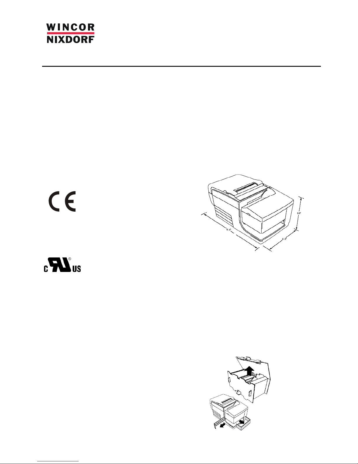
The TH320 printer requires minimal counter space
and may be set on or near the host computer.
With the RS232C interface, you can place the printer
up to 50 feet (15m), for USB interface up to 15 feet
(5m) and for Powered USB 12.5 feet (3.8m) from the
host computer and power supply.
Do not place the printer in a dusty environment or
anywhere that spillage of drinks or other liquids can
occur.
Be sure the printer is on a level surface and that there
is enough room to open the receipt cover to change
the paper and to open the front cover to change the
impact printer’s ribbon cassett e.
Be sure to leave adequate space at the rear the
printer for connecting and accessing the cab les .
Be sure to locate the printer away from sources of
magnetic interference. If the printer has a built in
Magnetic Ink Character Recognition (MICR) check
reader (option), you may need to make additional
adjustments to the printer’s location. Devices such as
CRT monitors or large metal surfaces can affect the
printer’s magnetic field and cause inter mitt ent che ck
reading errors.
Unpack the printer
The packing materials protect the printer and hel p
prevent damage.
Be sure to save all the packaging materials - including
the plastic bag and the cardboard supports found in
the slip path.
11.4’’
6.5’’
6.6’’
Page 2
Check the packing list
Before installation, check that all the items on this list
are included (printers shipped in bulk may not include
all these items):
• Printer (enclosed in a plastic bag with
corrugated pack)
• Thermal receipt sample paper roll
• Test printout protecting the print head (inside
receipt bucket)
• Ribbon cassette
• Setup Guide
Report Any Missing or Damaged Items
To report any missing materials or to report a printer
that was damaged during shipping, contact your
Wincor Nixdorf branch office.
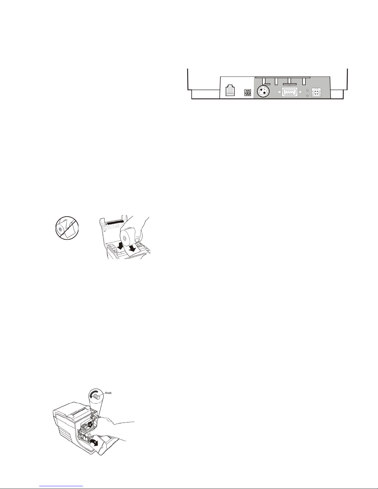
Install new receipt paper
1 Open the receipt cover and remove the used roll (if
present).
2 Tear off the end of the new roll so that the edge is
loose.
3 Place the roll into the paper bucket with the paper
unrolling from the bottom of the roll, and with a few
inches of paper extending over the cabinet front.
Paper must unroll from the
bottom of the roll to insure
that the image prints correctly
4 Close the receipt cover while holding the paper over
the front of the cabinet.
5 Remove the excess paper by tearing it against the
tear-off blade.
6 Press the paper feed button to advance the paper if
necessary.
Install the ribbon cassette
1 Open the front cover (1) by grasping the cover on
each side at the bottom and swing up.
2 Unwrap the new ribbon cassette and tighten the
ribbon by turning the knob on the cassette in the
direction of the arrow.
3 Position the ribbon cassette onto the carriage (2), as
shown, making sure the ribbon is not caught on the
print head.
4 Snap the cassette into place and snap the front
cover closed.
Connect the cables
All cable connections are made at the rear of the
printer.
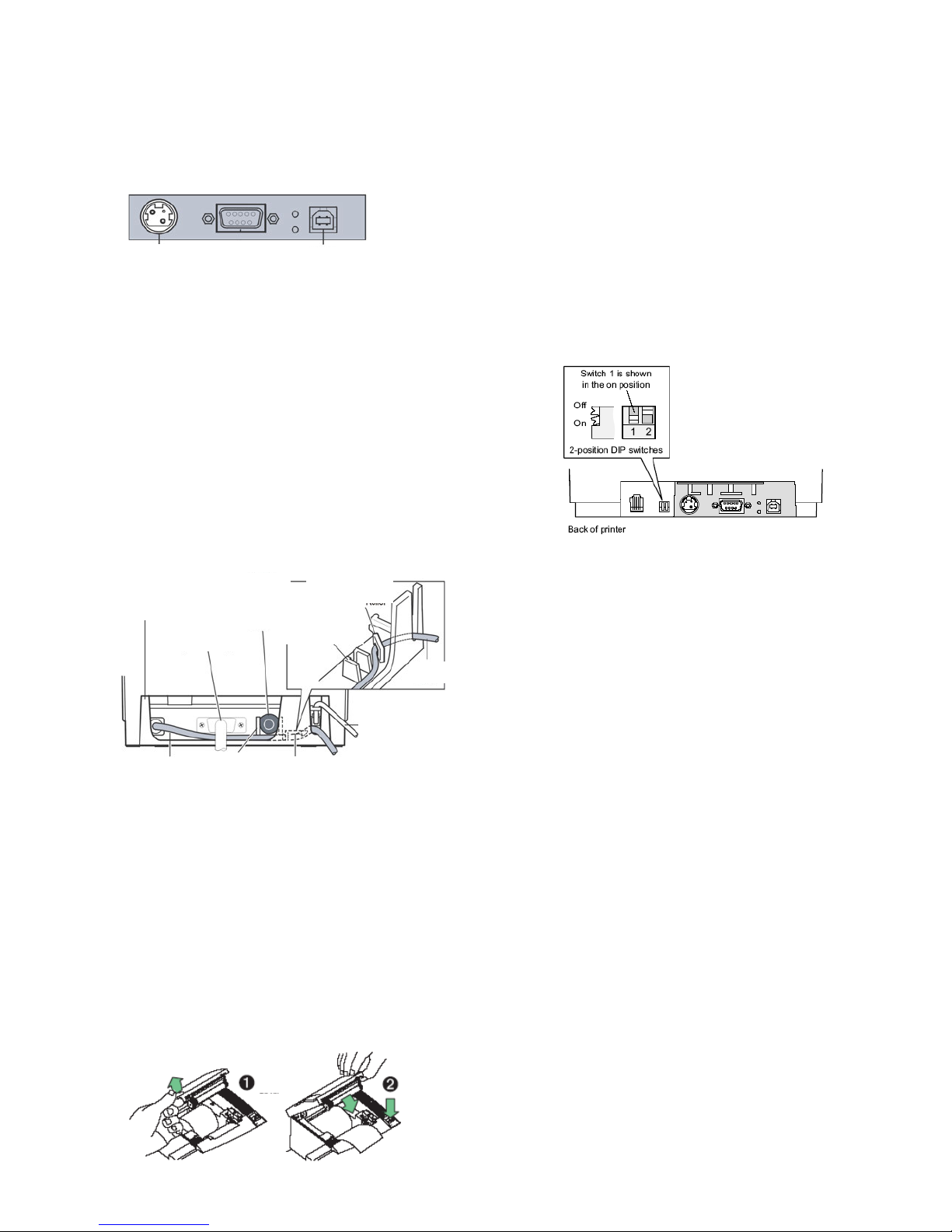
Note: The rear connector panel varies with
different interfaces
Cash drawer cables
Plug the cable into the cash drawer connector
(standard phone jack) next to the pair of dip switches
on the rear of the printer.
Communication cables
The communication cable connects the printer to the
host computer.
Route all cables as shown in Cable Routing to provide
strain relief.
If installing the RS232C communication
cable:
1 Turn off the host computer.
2 Plug the communication cable into the conne ctor.
3 Secure the connector by tightening the screws.
4 Connect the cable to the host computer.
5 Turn host computer on.
If installing the USB communication cable:
Caution: Be careful to connect the USB cable only
into the USB connector. Attempts to connect the
USB cable into the cash drawer connector can
cause permanent damage to the communications
circuitry.
1 Be sure the host computer is powered off.
2 Plug the printer end of the USB cable into the USB
connector port on the printer (A).
3 Plug the computer end of the USB cable into the
computer. Make sure the USB symbol on the
connector is facing up.
4 Download the USB driver to the host computer from
the Wincor Nixdorf Web site if necessary.
If installing the Powered USB cable:
1 Be sure the host computer is powered off.
2 Plug the printer end of the USB cable into the USB
connector port on the printer.
3 Plug the computer end of the USB cable into the
computer.
4 D
ownload the USB driver to the host computer from
the Wincor Nixdorf Web site if necessary.
Caution: DO NOT remove
the transparent mylar shield
that protects the exposed
ribbon.
Cash DIP Power RS232C USB
drawer switches supply
Page 3

Power supply cable
Caution: To avoid damage to the printer, connect
the power supply cable only with power “off” at
the BEETLE or external power supply.
WARNING! Using this device without a grounded
outlet is a safety hazard and voids the printer
Warranty, Safety, FCC and CE Mark designation
1 Plug the power cord into the power supply or use
BEETLE direct Power DC out.
2 Route the cash drawer and power supply cables
through the strain relief as shown below.
3 Plug the power cord into the power supply, then plug
the power supply into an outlet. The green light on the
top cover will light up.
Cable routing
Prevent the printer from being accidentally unplugged
by making sure the cables are routed as shown below.
Testing the printer
The test prints a complete list of printer sett ing s
(Diagnostic form) and partially cuts the paper. The test
items listed depend on the printer model.
Instructions at the bottom of the printout describe how
to enter the configuration menu and change the
current settings of the printer.
Test Procedure
1 To run the test:
a Open the receipt cover (1), then
b while holding down the paper feed button
(2) close the receipt cover.
2 Release paper feed button when the printer begins
printing the diagnostic printout.
3 Review the printout for printer settings.
To change any of these settings go to the
configuration menu as directed at the bottom of the
printout.
Configuring the printer
The configuration menu allows you to select functions
or change various settings for the printer. Instructions
printed on the receipt, guide you through the
processes.
Configuration Procedure
1 Open the receipt cover be sure there is paper in the
printer.
2 Turn Printer off and close the receipt cover.
Caution: Be extremely careful changing any of the
printer settings to avoid inadvertently changing
other settings that might affect the performance of
the printer.
3 Set DIP switch 1 (below) to the On position (down).
Turn the power on, then press and hold the paper
feed button. The printer prints the diagnostic form and
the configuration main menu.
Follow the printed instructions on the scrolling menu
by pressing the paper feed button to make Yes/ No
selections.
• • Indicate Yes with a long click. (Press and
hold paper feed button for at least one
second.)
• • Indicate No with a short click. (Press paper
feed button quickly)
Continue through your menu selections until you are
asked,
“Save New Parameters?” Select “Yes” or “No”.
a To save, select “Yes”, then return DIP
switch 1 to the Off position (up).
b Press the reset button. The printer resets
with the new selections. You can verify the
setting by printing a diagnostics form.
If you want to continue configuring the printer, select
“No”. The printer returns to the configuration menu.
Page 4

To change max power setting
Referring to the supplying BEETLE 24V DC-out
specification or to an external power supply, this value
needs to be set to 48, 55 or 75 watts.
Communication interface
Change the communication interface settings (except
Ethernet) by selecting “Set Communication Interface”
from the main menu and answer “Yes” to “SET
INTERFACE TYPE?”
Press the paper feed button as instructed to select the
communication interface you want.
To change RS232C serial interface settings
Select “Set Communication Interface” from the main
menu and answer “No” to “SET INTERFACE TYPE?”
to go to the instructions for selecting the RS232C
settings.
Press the paper feed button to select the RS232C
setting you want to change:
• Baud rate - (1200 to 115200 baud, delivery
default 19200)
• Hardware flow control:
Software - (XON/XOFF)
Hardware - (DTR/DSR)
• Data reception errors: Ignore errors, Print “?”
• Alternate DTR/DSR - Enabled Disabled
Note: Number of data bits, Stop bits, and Parity
parameters can not be changed and are not
shown.
Press the paper feed button for at least one second to
validate the selection.
Emulation/Software options
To change the printer emulation, printer ID, receipt
default lines per inch (LPI), or font size, enter this
section through the configuration menu.
Press the paper feed button to select the setting you
want to change:
• Printer emulations: Native or A756
• Printer ID: TH320 native, A758, or A756
• Default line space:
8.13, 7.52, 6.77, or 6 lines per inch
• Font size: standard, tall, …
Slip Setting options
To change the TH320 slip setting options, enter this
section through the emulation software options section
of the configuration menu.
Press the paper feed button to select the setting you
want to change:
• Ignore n leading spaces in a 47 column text
• Enable 51-column compressed mode
• Delete the trailing spaces in a slip text line
• Set the TH320 to emulate the A758 slip stop
position
Select Paper Type
To change the paper type, enter the section through
the configuration menu.
Press the paper feed button to select the setting you
want to change.
Note on the print head
The print head is a thermal element and
it is at high temperature during printing
or just after operation, therefore please
do not touch it and its peripherals for
safety reasons.
The thermal head is an ESD-sensitive
device. To prevent damage, do not
touch either its printing part or
connecting parts.
Further Information
Please find detailed information about the printer in
the Operator’s Guide. This document can be
download as PDF file from the following Web site:
http://www.wincornixdorf.com/internet/com/Services/Support/TechnicalS
upport/POSSystems/Manuals/index.html
Consumables
Please order consumables at:
http://www.wincor-nixdorf.com/mediaservice
Copyright© Wincor Nixdorf International GmbH, 2013
The reproduction, transmission or use of this document or its
contents is not permitted without express authority.
Offenders will be liable for damages.
All rights, including rights created by patent grant or
registration of a utility model or design, are reserved.
Delivery subject to availability; technical modifications
possible.
TH320-SUGWN01 rev D
Page 5
TH320
Kurzbeschreibung
Gewährleistung
Wincor Nixdorf sichert Ihnen eine beschränkte
Gewährleistung von 12 Monaten ab Lieferdatum zu.
Diese Gewährleistung bezieht sich auf alle Defekte,
die bei normaler Verwendung des Produkts
aufgetreten sind.
Defekte aufgrund
- unsachgemäßer oder ungenügend er Wartung
- unsachgemäßer Verwendung oder
unberechtigter Veränderungen am Produkt
- eines ungeeigneten Standortes oder
ungeeigneter Umgebung
sind nicht abgedeckt.
Verwenden Sie nur Netzteile und Kabel, die von
Wincor Nixdorf freigegeben sind.
Bescheinigung des Herstellers
Dieses Gerät erfüllt die
Anforderungen der EG-Richtlinien
2004/108/EG “Elektromagnetische
Verträglichkeit” sowie
RoHS 2011/65/EU.
Hierfür trägt das Gerät die CE-Kennzeichnung auf der
Rückseite oder das Zeichen befindet sich auf der
Verpackung.
Geprüfte Sicherheit
Der Drucker besitzt die UL- und
cUL-Zulassung.
Aufstellungsort
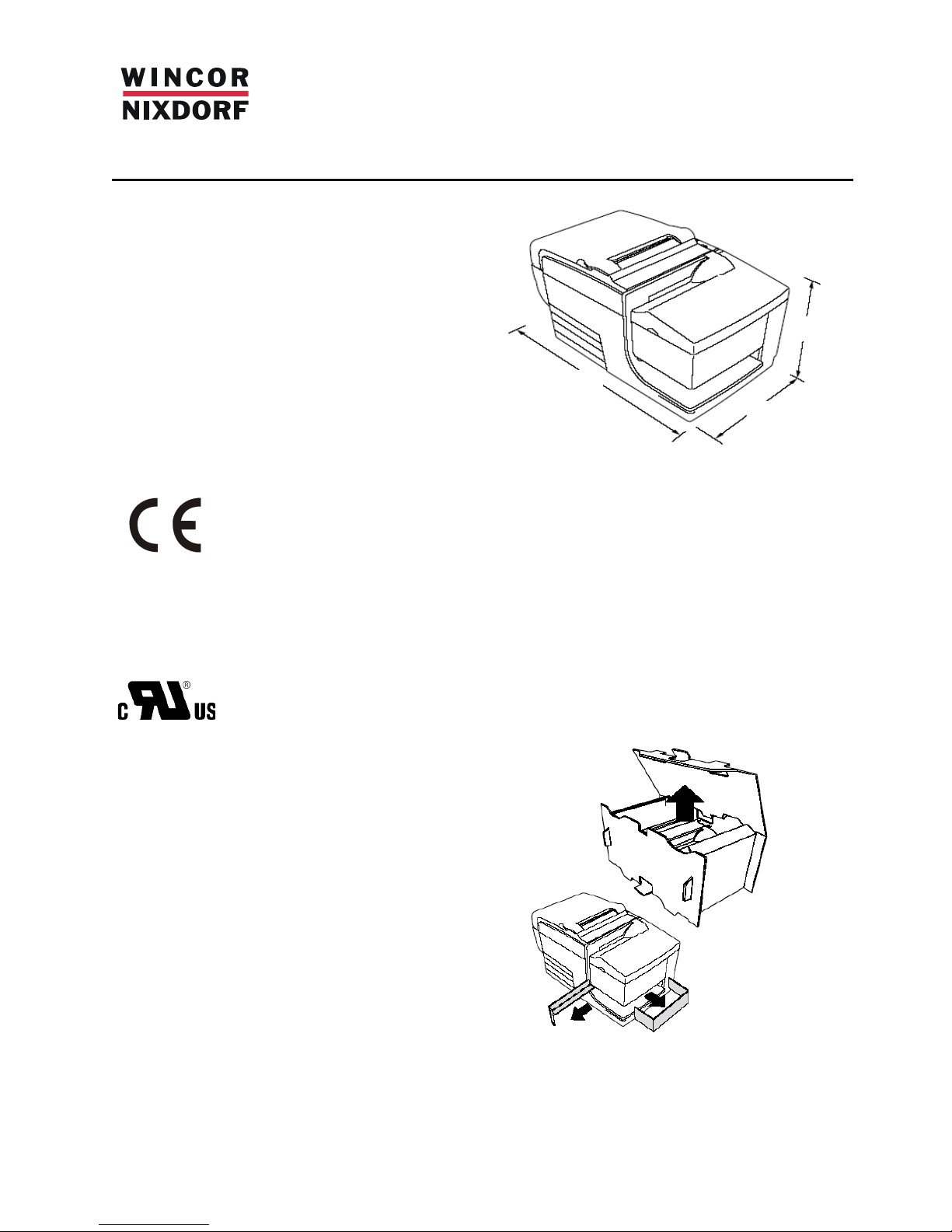
Der TH320 benötigt eine geringe Stellfläche und sollte
in der Nähe des Kassensystems aufgestellt werden.
Die Entfernung zum Kassensystem und zur
Stromversorgung beträgt bei einer RS232CSchnittstelle bis zu 15m, bei einer USB-Schnittstelle
5m und bei einer Powered USB-Schnittstelle 3,8m.
Stellen Sie den Drucker nicht in eine staubige
Umgebung oder an Orte wo Getränke oder andere
Flüssigkeiten verschüttet werden können.
Der Drucker benötigt eine ebene Unterlage. Zum
Öffnen der Bonabdeckung für den Rollenwechsel und
zum Öffnen der vorderen Abdeckung zum
Farbbandwechsel sollte der Drucker über genügend
Platz verfügen.
Berücksichtigen Sie genug Platz an der Rückseite des
Druckers für die Handhabung der Steckverbindungen.
Achten Sie darauf, dass der Drucker keinen elektromagnetischen Störquellen ausgesetzt ist. Falls der
Drucker die MICR Option enthält muss der
Aufstellungsort entsprechend angepasst werden.
CRT Monitore und große Metallflächen können das
Magnetfeld des Druckers beeinflussen und zur
zeitweisen Störung bei der Scheckerkennung führen.
Auspacken des Druckers
Heben Sie das gesamte Verpackungsmaterial für
einen späteren Versand oder zur Lagerung auf,
besonders ist beim erneuten Versand die Verwendung
der Karton-Abstandshalter zu beachten .
290 mm
165 mm
168 mm
Page 6
Überprüfen des Lieferumfangs
Vergleichen Sie den Lieferumfang mit dem
Lieferschein:
• Drucker in einer Plastiktüte mit
Verpackungsmaterial
• Erste Thermopapierrolle
• Testausdruck zum Schutz der Druckzeile
• Farbband-Kassette
• TH320 Kurzbeschreibung
Bei Beschädigungen oder Unstimmigkeiten wenden
Sie sich an Ihre zuständige Wincor Nixdorf
Geschäftsstelle
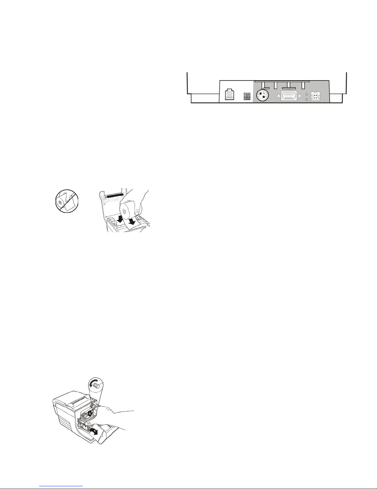
Bonrolle wechseln
1 Öffnen Sie die Bonabdeckung und entfernen Sie die
verbrauchte Bonrolle (soweit vorhanden).
2 Lösen Sie das Ende der neuen Bonrolle.
3 Legen Sie die Rolle in die Papieraufnahme so dass
sie von unten abrollt und einige Zentimeter über den
vorderen Gehäuserand ragen.
Für einen korrekten Ausdruck
muss das Papier von unten
abrollen.
4 Schließen Sie die Bonabdeckung während Sie das
Papier über den vorderen Gehäuser and halt en.
5 Entfernen Sie das überschüssige Papier indem Sie
es über die Abrisskante ziehen.
6 Falls nötig drücken Sie die Paper Feed Taste für
einen Papiervorschub.
Einsetzen der Farbbandkassette
1 Drücken Sie die vordere Abdeckung (1) an beiden
Seiten bis sie ausrastet und klappen Sie sie nach
oben.
2 Packen Sie die neue Farbbandkassette aus und
spannen Sie das Farbband indem Sie den Knopf auf
der Kassette in Pfeilrichtung drehen.
3 Setzen Sie die Kassette in den Träger (2) ein (siehe
Abbildung), vermeiden Sie ein verhaken des
Farbbands mit dem Druckkopf.
4 Rasten Sie die Kassette ein und schließen Sie die
vordere Abdeckung.
Verkabelung des TH320
Alle Kabelverbindungen befinden sich auf der
Rückseite des Druckers.
Hinweis: Abhängig von Ihrer Druckervariante kann
die oben dargestellte Anschlussleiste abweichen.
Kabel zur Kassenlade
Stecken das Kabel in den Kassenladeanschluss an
der Rückseite des Druckers
Kabel für Systemanschluss
Verbinden Sie den Drucker und das Kassensystem
mit einem Kabel, das den vorhandenen Schnittstellen
entspricht
Verlegen Sie alle Kabel wie in der „Kabelführung“
beschrieben um die Zugentlastung zu nutzen.
Anschluss eines RS232C-Kabels:
1 Schalten Sie das Kassensystem aus
2 Stecken Sie das Kommunikationskabel in den
Anschluss des Druckers
3 Sichern Sie den Anschluss durch Befestigen der
Schrauben
4 Verbinden Sie das Kabel mit dem Kassensystem
5 Schalten Sie das Kassensyste m ein
Anschluss eines USB-Kabels
Achtung: Schließen Sie das Kabel nur an der USBBuchse an. Ein Anschluss an der KassenladeBuchse kann zu einem dauerhaften Schaden der
Elektronik führen.
1 Schalten Sie das Kassensystem unbedingt aus.
2 Stecken Sie das Druckerende des USB-Kabels in
die USB-Buchse am Drucker.
3 Stecken Sie das Systemende des USB-Kabels in die
USB-Buchse des Kassensystems. Das USB-Symbol
muss dabei nach oben zeigen.
4 Laden Sie, falls nötig, den USB-Treiber für das
Kassensystem von der Wincor Nixdorf Internetseite
Anschluss eines Powered USB-Kabels:
1 Schalten Sie das Kassensyste m unbedingt aus.
2 Stecken Sie das Druckerende des USB-Kabels in
die USB-Buchse am Drucker.
3 Stecken Sie das Systemende des USB-Kabels in
die USB-Buchse des Kassensystems.
4 Laden Sie, falls nötig, den USB-Treiber für das
Kassensystem von der Wincor Nixdorf Internetseite.
Caution: DO NOT remove
the transparent mylar shield
that protects the exposed
ribbon.
Kassen- DIP- Spannungs- RS232C USB
lade schalter versorgung
Knopf
Achtung! Entfernen Sie nicht die
transparente Folie zum Schutz des
offenen Farbbands.
Page 7
Kabel zur Spannungsversorgung
Achtung: Stecken Sie das Kabel zur Spannungsversorgung immer bei ausgeschal tet em BEETLE
/externem Netzteil, um eine B eschäd ig ung des
Druckers zu vermeiden.
WARNUNG! Wenn Sie den Drucker ohne geerdeten
Anschluss betreiben ist dies eine
Sicherheitsgefährdung und lässt die Bestimmungen
zur Gewährleistung, Sicherheit und CEKennzeichnung ungültig werden.
1 Stecken Sie das Spannungskabel in die Buchse am
Drucker oder benutzen Sie die Spannungsversorgung
(DC out) direkt vom BEETLE-System.
2 Führen Sie das Spannungs k abel und das
Kassenladenkabel in die Zugentlastung (siehe unten).
3 Verbinden Sie das Spannungskabel mit dem Netzteil
und dieses mit der Hausinstallation. Das grüne Licht
auf der Abdeckung leuchtet auf.
Kabelführung
Vermeiden Sie ein unbeabsichtigtes Lösen der Kabel
indem Sie die Kabel wie unten beschrieben verlegen.
Druckertest
Der Test druckt eine komplette Liste der Einstellungen
aus und schneidet das Papier an. Die Angaben sind
vom Druckermodell abhängig. Hinweise am Ende des
Ausdrucks beschreiben, wie man ins KonfigurationsMenü gelangt und wie man aktuelle Einstellungen
ändert
Test-Aufruf
1 Um den Test zu starten:
a Öffnen Sie die Bon-Abdeckung (1)
b halten Sie den Paper Feed Button gedrück t
(2) während Sie die Bon-Abdeckung
schließen.
2 Lassen Sie den Paper Feed Button los, sobald der
Ausdruck beginnt.
3 Überprüfen Sie die Einstellungen auf dem Ausdruck.
Um Änderungen an den Einstellungen vorzunehmen,
öffnen Sie das Konfigurationsmenü wie am Ende des
Ausdrucks beschrieben.
Einstellungen des Druckers
Über das Konfigurationsmenü können Sie
Druckerfunktionen wählen und Einstellungen ändern.
Hinweise am Ende des Bons führen Sie durch den
Prozessablauf.
Konfigurations-Prozess
1 Öffnen Sie die Bonabdeckung und stellen Sie sicher,
dass sich Papier im Dru cker b efind et .
2 Schalten Sie den Drucker aus und schließen Sie die
Bonabdeckung.
Achtung: Seien Sie besonders vorsichtig bei der
Veränderung der Einstellungen um ein
versehentliches Ändern anderer Einstellungen zu
vermeiden und dadurch die Leistung des Druckers
zu beeinflussen.
3 Kippen Sie den DIP-Schalter 1 in die On-Position
(untere Stellung).
Schalten Sie den Drucker ein und halten Sie den
Paper Feed Button gedrückt. Es erfolgt ein Ausdruck
der Diagnosedaten und des Konfigurati on sHauptmenüs.
Folgen Sie den ausgedruckten Hinweisen des Menüs
und drücken Sie den Paper Feed Button um eine
YES/NO-Auswahl zu treffen.
• Wählen Sie YES durch ein langes Anklicken
(halten Sie den Paper Feed Button für
mindesten eine Sekunde gedrückt)
• Wählen Sie NO durch ein kurzes Anklicken
(drücken Sie kurz den Paper Feed Button)
Folgen Sie dem Menü bis zur Frage “Save New
Parameters?” Select “Yes” or “No”.
a) Um die geänderten Einstellungen zu
sichern wählen Sie YES, kippen Sie den DIPSchalter 1 in die Off-Position (obere Stellung)
b) Drücken Sie den Reset Button. Der
Drucker übernimmt die Neueinstellungen. Sie
können die neuen Einstellungen durch den
Ausdruck eines Diagnoseformulars
überprüfen.
Wenn Sie mit der Konfigurierung des Druckers
fortfahren möchten drücken Sie NO. Der Drucker
kehrt in das Konfigurationsmenü zurück.
AnschlussAbdeckung
(geschlossen)
RS232C-
Anschluss(verschraubt)
Span-
nungskabel
Spannungs-
kabel
Zugentlastung
USB-Kabel
Zugentlastung
USB-Kabel
USB-
Kabel
USB-
Kabel
Zugentlastung
SpannungsKabel
Zugentlastung
Kassenlade
Kabel
Spannungs-
versorgung
USBAnschluss
Page 8

Änderung der maximal verfügbaren
Leistungs-Einstellung
Entsprechend der Spezifikation der BEETLE 24V DC
Spannungsversorgung oder ei nes externen Netzteils
muss der Wert auf 48, 55 oder 75 Watt gesetzt
werden.
Schnittstelle zur Datenkommunikation
Ändern Sie die Einstellungen der Schnittstelle mit der
Auswahl von “Set Communication Interface” aus dem
Hauptmenü und bestätigen Sie YES bei “SET
INTERFACE TYPE?”.
Drücken Sie den Paper Feed Button um die
entsprechende Schnittstelle auszuwählen.
Änderung der RS232C Einstellungen
Wählen Sie “Set Communication Interface” aus dem
Hauptmenü und setzen Sie NO bei “SET INTERFACE
TYPE?” um zu den Hinweisen zur Auswahl der
RS232C Einstellungen zu gelangen.
Drücken Sie den Paper Feed Button um auszuwählen
welche Einstellungen der RS232C geändert werden
sollen
• Baud rate - (1200 to 115200 baud, delivery
default 19200)
• Hardware flow control:
Software - (XON/XOFF)
Hardware - (DTR/DSR)
• Data reception errors: Ignore errors, Print “?”
• Alternate DTR/DSR - Enabled Disabled
Hinweis: Anzahl der Datenbits, Stoppbits und
Parity-Parameter können nicht geändert werden
und werden nicht angezeigt.
Drücken Sie den Paper Feed Button für mindestens
eine Sekunde um die Auswahl zu bestätigen.
Emulation/Software Optionen
Wählen Sie diesen Abschnitt im Konfigurationsmenü
um die Druckeremulation, die D rucker-ID, die Zeil en
pro Zoll auf dem Bon und die Schriftgröße zu ändern.
Drücken Sie den Paper Feed Button um auszuwählen
welche Einstellungen geändert werden sollen.
• Druckeremulation: Native oder A756
• Drucker-ID: TH320 native, A758, oder A756
• Standardzeilenabstand:
8.13, 7.52, 6.77, oder 6 Zeilen pro Zoll
• Schriftgröße: standard, tall, …
Belegoptionen
Um die Belegoptionen zu ändern wählen Sie zunächst
die Emulation/Software Optionen aus dem
Konfigurationsmenü.
Drücken Sie den Paper Feed Button um auszuwählen
welche Einstellungen geändert werden sollen
• Ignorieren von n führenden Le er z eiche n bei
einem Text mit 47 Spalten.
• Aktivieren des komprimierten Modus mit 51
Spalten
• Entfernen von nachfolgenden Leerz eic hen in
einer Belegzeile
• Emulation der A758 Belegende-Position für
den TH320
Auswahl der Papierart
Ändern Sie die Papiervariante über das
Konfigurationsmenü.
Drücken Sie den Paper Feed Button um auszuwählen
welche Einstellungen geändert werden sollen.
Hinweise zum Druckkopf
Der Druckkopf ist ein Thermoelement,
das sich beim Drucken stark erhitzt.
Berühren Sie auch nach dem Drucken
nicht den Bereich.
Der Druckkopf ist ein elektrostatisch
gefährdetes Bauteil. Um
Beschädigungen zu vermeiden,
berühren Sie weder den Druckkopf
noch dessen Umgebung.
Weitere Informationen
Weitergehende Information en über den Dru cker
finden Sie im Benutzerhandbuch. Dieses Handbuch
erhalten Sie als Download im PDF-Format unter
folgender Web-Adresse:
http://www.wincornixdorf.com/internet/de/Services/Support/TechnicalSu
pport/POSSystems/Manuals/index.html
Verbrauchsmaterialien
bestellen Sie bitte unter:
http://www.wincor-nixdorf.com/mediaservice
Copyright ©Wincor Nixdorf International GmbH , 2013
Alle Rechte vorbehalten, insbesondere (auch auszugsweise) die der
Übersetzung, des Nac hd ruck s , Wiedergabe durch Kopieren oder
ähnliche Verfahren. Zuwiderhandlungen verpflichten zu
Schadensersatz. Alle Rechte vorbehalten, insbesondere für den Fall
der Patenterteilung od er GM-Eintragung. Liefermöglichkeiten und
technische Änderungen vorbehalten
.
TH320-SUGWN01 rev D
 Loading...