

Wincor Nixdorf TH250 Programmer's Manual
TH250
Thermal Printer
Programmer’s Guide (January 2016)

Contents
About this Guide ........................................................................................................................... 1
How to use this guide .................................................................................................................... 1
Where to find the basics ................................................................................................................ 1
Where to find advanced technical information .............................................................................. 1
Support ....................................................................................................................................... 1
Diagnostics and Configuration ...................................................................................................... 2
Start-up Diagnostics ................................................................................................................... 2
Runtime Diagnostics ...................................................................................................................... 3
Remote Diagnostics ....................................................................................................................... 3
Accessing the remote diagnostic tallies ...................................................................................... 4
Indicators ...................................................................................................................................... 5
Error conditions and correcting them......................................................................................... 5
Communication of printer status to the host application ........................................................... 5
Printer configuration ..................................................................................................................... 6
Configuring the printer ............................................................................................................... 7
Communication interface settings.............................................................................................. 8
Diagnostics modes ..................................................................................................................... 8
Enable or disable data scope mode ............................................................................................ 9
Enable or disable receipt test mode ........................................................................................... 9
Electronic Journal Datascope Diagnostic .................................................................................. 10
Printer emulations ....................................................................................................................... 10
Printer settings and functions .................................................................................................. 10
Programming the Printer ............................................................................................................ 13
Overview of commands ............................................................................................................... 13
Comparison to A793 .................................................................................................................... 13
Two-color commands (comparison TH210 to TH250) .................................................................. 15
Character appearance ................................................................................................................. 16
Width specifications .................................................................................................................... 16
Print zones................................................................................................................................... 16
Print zones for 80mm paper ..................................................................................................... 16
Emulation modes ......................................................................................................................... 18
Print setup in emulation modes ............................................................................................... 18
Programming Commands ........................................................................................................... 19
Commands listed by function ...................................................................................................... 19
Command conventions ................................................................................................................ 28
Command descriptions ................................................................................................................ 28
Printer actions ......................................................................................................................... 28
Print and paper feed ................................................................................................................ 36
Text characteristics commands ................................................................................................ 45
Double-byte fonts .................................................................................................................... 61
Graphics ................................................................................................................................... 64
Status .......................................................................................................................................... 78
Status command introduction ..................................................................................................... 78
Batch mode.............................................................................................................................. 78
Real time commands................................................................................................................ 81
Rules for using real time commands ........................................................................................ 82

Automatic Status Back ............................................................................................................. 87
Unsolicited status mode........................................................................................................... 89
Bar codes .................................................................................................................................... 93
QR code Overview ....................................................................................................................... 93
Select model for QR code ......................................................................................................... 93
Set size for QR code module .................................................................................................... 93
Set data parsing mode for QR Code ......................................................................................... 94
Select error correction level for QR Code ................................................................................. 94
Store symbol data for QR Code ................................................................................................ 94
Print symbol data for QR code ................................................................................................. 95
Select printing position of HRI characters ................................................................................. 96
Select pitch of HRI characters ................................................................................................... 96
Select bar code height .............................................................................................................. 97
Print bar code .......................................................................................................................... 97
Print multiple barcodes ............................................................................................................ 99
Print GS1 DataBar, null terminated .........................................................................................100
Print GS1 DataBar, data length specified .................................................................................100
Set GS1 DataBar parameters ...................................................................................................101
Select PDF 417 parameters .....................................................................................................101
Select bar code width..............................................................................................................103
Set DataMatrix Parameters .....................................................................................................103
Set DataMatrix Module size ....................................................................................................104
Store DataMatrix data in symbol storage area ........................................................................105
Print DataMatrix symbol data in the symbol storage area .......................................................105
Page mode ................................................................................................................................ 107
Print and return to standard mode ............................................................................................ 107
Cancel print data in page mode ................................................................................................. 107
Print data in page mode ............................................................................................................ 108
Select page mode ...................................................................................................................... 108
Select standard mode ................................................................................................................ 109
Select print direction in page mode ........................................................................................... 109
Select print area in page mode .................................................................................................. 110
Set absolute vertical print position in page mode ...................................................................... 111
Set relative vertical print position in page mode ........................................................................ 112
Macros ...................................................................................................................................... 113
Select or cancel macro definition ............................................................................................... 113
Execute macro ........................................................................................................................... 113
User data storage ...................................................................................................................... 115
Write to user data storage ......................................................................................................... 115
Read from user data storage ..................................................................................................... 115
Select memory type (SRAM/flash) where to save logos or user-defined fonts ........................... 115
Flash memory user sectors allocation ........................................................................................ 116
Flash object area pack ............................................................................................................... 117
Flash object delete .................................................................................................................... 117
Expanded flash memory allocation ............................................................................................ 117
Select flash area for storing logos and user-defined characters ................................................. 118
Return flash area size ................................................................................................................ 118
User storage status .................................................................................................................... 119
Lock permanent font flash area ................................................................................................. 120

Flash download ......................................................................................................................... 120
Switch to flash download mode ................................................................................................. 121
Erase all flash contents except boot sector ................................................................................ 121
Return main program flash CRC ................................................................................................. 121
Download application ................................................................................................................ 121
Reset firmware .......................................................................................................................... 122
Ethernet setup commands ........................................................................................................ 123
Restore default settings ............................................................................................................. 123
Set IP address ............................................................................................................................ 123
Set Net Mask ............................................................................................................................. 123
Set Gateway .............................................................................................................................. 124
Set raw TCP/IP port ................................................................................................................... 124
DHCP (auto-configuration) ......................................................................................................... 124
Inactivity timeout ...................................................................................................................... 124
Keep-alive pings......................................................................................................................... 125
Set HTTP port ............................................................................................................................ 125
Get Ethernet configuration ........................................................................................................ 125
Settings commands ................................................................................................................... 127
Save current settings ................................................................................................................. 127
Restore factory settings .............................................................................................................. 127
Upload current settings .............................................................................................................. 127
Upload factory settings .............................................................................................................. 127
Download settings ..................................................................................................................... 127
Black bar commands ................................................................................................................. 128
Set black bar flags ...................................................................................................................... 128
Enable feed to mark on form feed ............................................................................................. 128
Enable feed to mark on cut ........................................................................................................ 128
Enable black bar paper low detection ........................................................................................ 128
Enable black bar max feed ......................................................................................................... 129
Enable black bar threshold ........................................................................................................ 129
Enable black bar offset .............................................................................................................. 129
Miscellaneous configuration commands .................................................................................. 130
Set diagnostics mode ................................................................................................................. 130
Enable or disable knife ............................................................................................................... 130
Enable or disable paper low sensor ........................................................................................... 130
Set max power ........................................................................................................................... 131
Set printer emulation ................................................................................................................ 131
Reset settings to default values ................................................................................................. 131
Set partial cut distance .............................................................................................................. 132
Set default font.......................................................................................................................... 132
Set font size ............................................................................................................................... 132
Set color density ........................................................................................................................ 132
Enable or disable Code 128 check digit calculation .................................................................... 133
Enable or disable barcode ITF leading zero ................................................................................ 133
Enable or disable barcode string terminator .............................................................................. 133
Set paper low threshold extension ............................................................................................ 134
Enable or disable USM canned status ........................................................................................ 134
Send diagnostic pages to comm port ......................................................................................... 134
Enable or disable EJ action via operator control ......................................................................... 134

Set fine adjustment of partial cut steps ..................................................................................... 135
Set printer ID mode ................................................................................................................... 135
Set default code page at power on ............................................................................................ 135
Set Asian ASCII characters to narrow ......................................................................................... 135
Set vertical white space ............................................................................................................. 136
Set printer tone ......................................................................................................................... 136
Enable or disable shutdown mode ............................................................................................. 136
Set shutdown mode timeout ..................................................................................................... 137
Set print quality level ................................................................................................................. 137
Appendix A: .............................................................................................................................. 138
TH230 Emulation Exceptions ..................................................................................................... 138
Appendix B: ............................................................................................................................... 141
Commands listed by hexadecimal code ..................................................................................... 141
Appendix C: ............................................................................................................................... 147
Resident Character Sets ............................................................................................................. 147
Character sets .........................................................................................................................147
Character code table Page 0 (PC437: USA, Standard Europe): .................................................147
Character code table Page 1 (PC850: Multilingual Latin I): ......................................................148
Character code table Page 2 (PC852: Latin II): .........................................................................149
Character code table Page 3 (PC860: Portuguese): ..................................................................150
Character code table Page 4 (PC863: Canadian French): .........................................................151
Character code table Page 5 (PC865: Nordic): .........................................................................152
Character code table Page 6 (PC858: Multilingual I + Euro): ....................................................153
Character code table Page 7 (PC866: Russian): ........................................................................154
Character code table Page 8 (WPC1252: Latin I): .....................................................................155
Character code table Page 9 (PC862: Hebrew): .......................................................................156
Character code table Page 10 (PC737: Greek): ........................................................................157
Character code table Page 11 (PC874: Thai): ...........................................................................158
Character code table Page 12 (PC857: Turkish): ......................................................................159
Character code table Page 13 (WPC1251: Cyrillic): ..................................................................160
Character code table Page 14 (WPC1255: Hebrew): ................................................................161
Character code table Page 15 ((KZ_1048: Kazakh): ..................................................................162
Character code table Page 16 (WPC1254: Turkish): .................................................................163
Character code table Page 17 (WPC1250: Central Europe): .....................................................164
Character code table Page 18 (WPC28591: Latin 1): ................................................................165
Character code table Page 19 (WPC28592: Latin 2): ................................................................166
Character code table Page 20 (WPC28599: Turkish): ...............................................................167
Character code table Page 21 (WPC28605: Latin 9): ................................................................168
Character code table Page 22 (PC864: Arabic): ........................................................................169
Character code table Page 23 (PC720: Arabic): ........................................................................170
Character code table Page 24 (WPC1256: Arabic): ..................................................................171
Character code table Page 25 (WPC28596: Arabic): ................................................................172
Character code table Page 26 (KATAKANA: Asia): ....................................................................173
Character code table Page 27 (PC775: Baltic): .........................................................................174
Character code table Page 28 (WPC1257: Baltic): ....................................................................175
Character code table Page 29 (WP28594: Baltic): ....................................................................176

TH250 Programmer’s Guide
About this Guide
How to use this guide
This is a supplemental guide providing programming information on Wincor Nixdorf’s TH250
printers. This guide is written for tech-savvy users who are interested in customizing or adjusting
printer functionality and is meant to be used in conjunction with the User Manual.
If you experience any difficulties during the programming process or feel unsure of adjustments
you have made, contact your Wincor Nixdorf representative for further assistance.
Where to find the basics
If you are looking for information on setup or basic operation, refer to the User Guide. The
programming guide assumes that you have the User Guide handy for reference or are already
familiar with the printer.
Where to find advanced technical information
This guide contains the most complete information available on programming the printer. If you
cannot find what you need here or would like further guidance on how to program the printer,
contact a Wincor Nixdorf representative for assistance.
If you are having problems with the physical operation of the printer, the Service Manual provides
in-depth information on diagnostics and service. The Service Manual is available to qualified
service technicians who have been certified by Wincor Nixdorf to perform advanced procedures.
Support
For more advanced procedures and troubleshooting, you may need to refer to the printer’s service
manual or speak to a Wincor Nixdorf technical professional. Your representative is able to provide
you with necessary information.
For online service, refer to the Web site at www.wincor-nixdorf.com.
1

TH250 Programmer’s Guide
Diagnostics and Configuration
The printer performs a number of diagnostics that provide useful information about the operating
status of the printer. The following diagnostic tests are available.
Start-up diagnostics
Perform during the printer’s start-up cycle.
Runtime diagnostics
Perform during normal printer operation.
Remote diagnostics
Maintained during normal operation and reported in the print test.
The printer can be configured with the following settings and functions through the
configuration menu that is printed on the receipt. For more information on configuring the
printer, see “Printer configuration” on page 6.
Communication interfaces:
Diagnostic modes
Printer emulations/software options
Hardware options
Paper Type
Firmware features
Start-up Diagnostics
When the printer receives power or performs a hardware reset, it automatically performs the
startup diagnostics (also known as level 0 diagnostics) during the start-up cycle. The following
diagnostics are performed:
Turn off motors
Perform boot CRC check of the firmware ROM and test main program CRC
Failure causes Start-up Diagnostics to stop; the printer beeps and the LED flashes a set number
of times, indicating the nature of the failure. The table in the “Indicators” section (page 14)
describes the specific tone and LED sequences.
Check if paper is present
Return the knife to the home position
Failure causes a fault condition. The table in the “Indicators” section (page 14) describes the
specific tone and LED sequences.
Check if receipt cover is closed
Failure does not interrupt the start-up cycle.
At power up, if the LED blinks twice, every four seconds, the object storage areas are being
initialized. This process could take up to two minutes. Once the object storage area initialization is
complete the printer will continue with its normal startup procedure and operation. DO NOT
RESET THE PRINTER UNTIL THIS PROCESS IS COMPLETE.
When the start-up diagnostics are complete, the printer makes a two-tone beep (low then high
frequency), the paper feed button is enabled, and the printer is ready for normal operation.
If the printer has not been turned on before, or a new EEPROM has been installed, the default
values for the printer functions will be loaded into the EEPROM during start-up diagnostics, and
the printer will make a quick four-tone beep (high then low frequency, twice).
2

TH250 Programmer’s Guide
Model number
Serial number
CRC number
Number of lines printed
Number of knife cuts
Number of hours the printer has been on
Number of flash cycles
Number of cutter jams
Number of times the cover is opened
Number of barcodes printed
Number of receipt characters printed
Number of printer faults
Maximum temperature reached
Number of dots printed
Number of dots printed on current printhead
Number of printhead changes
Number of receipt mechanism changes
Number of knife mechanism changes
Number of black mark errors
Number of thermistor errors
Number of low voltage errors
Number of high voltage errors
Number of firmware starts
Number of EEPROM updates
Runtime Diagnostics
Runtime diagnostics (sometimes called level 2 diagnostics) run during normal printer operation.
When the following conditions occur, the printer automatically turns off the appropriate motors
and disables printing to prevent damage to the printer:
Paper out
Receipt cover open
Knife unable to home
Printhead too hot
Voltages out of range
The LED on the operator panel will signal when these conditions occur as well as indicate what
state or mode the printer is in.
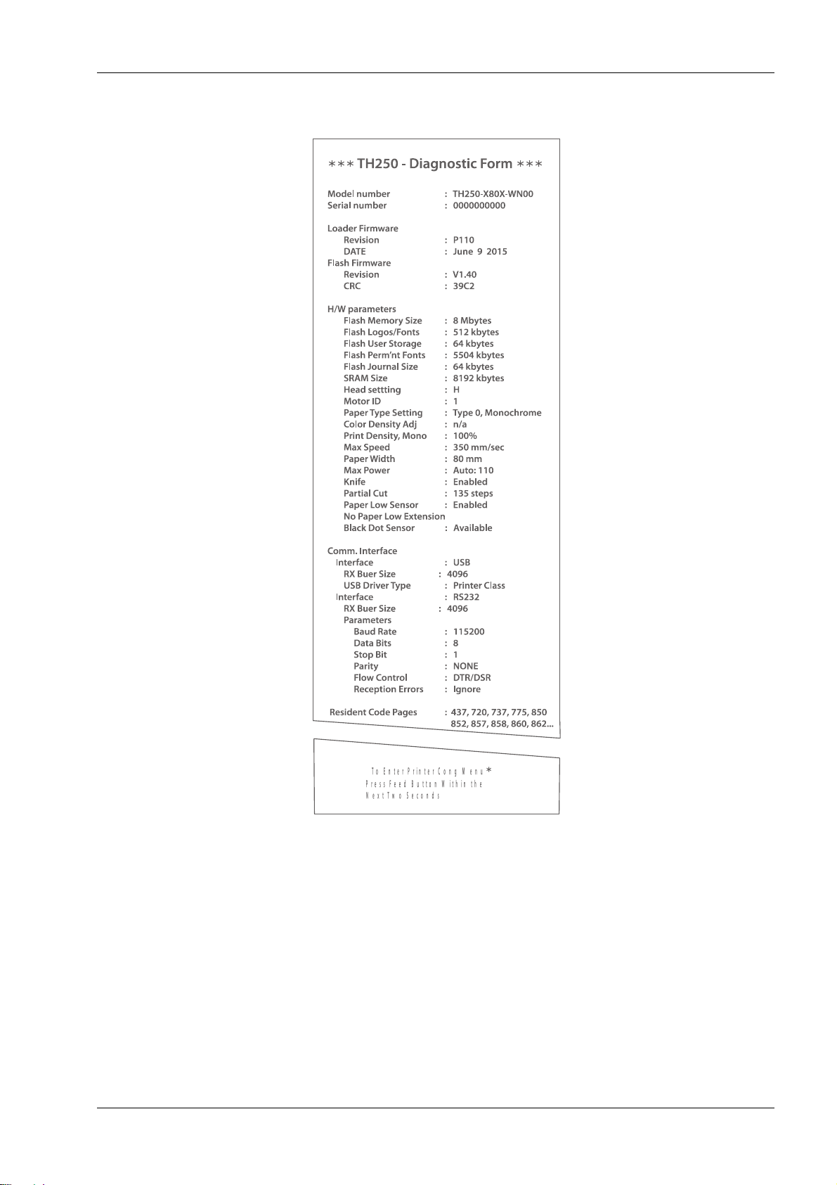
Remote Diagnostics
Remote diagnostics (sometimes called level 3 diagnostics) keeps track of the following tallies and
prints them on the receipt during the print test. See the sample test printout on the next page.
These tallies can be used to determine the printer’s state of health.
3
TH250 Programmer’s Guide
TH250 Diagnostics Form
*** ***
Print test will vary per model or printer configuration.
Accessing the remote diagnostic tallies
Refer to “Command descriptions” in Chapter “Programming commands“
(Status commands: Transmit printer ID, remote diagnostics extension, Hexadecimal 1D 49 40 n)
4
TH250 Programmer’s Guide
Indicator
Sequence
Condition
LED
Continuous, blinking on
Paper out
Cover open
Black dot sensor error
Knife unable to home
LED
Continuous, blinking off
Paper is low
Printhead too hot
Voltages low/high
LED
Continuous, double LED flash
Write to permanent memory in progress
LED
Blinks once every five seconds
Printer in sleep mode
LED
Continuous, quick blinking (on
power up)
Invalid firmware
LED
Continuous, slow blinking
Power supply and max power setting
don’t match
Tone
Two-tone beep (low frequency,
high frequency)
Start-up diagnostics completed
successfully
LED and
Tone
Two-tone beep (low frequency,
high frequency)
Continuous, quick blinking of LED
When entering flash download mode*
*Note: The printer enters flash download mode when a download command
is sent to the printer.
Indicators
The printer communicates various conditions both visually, with the green LED or audibly, with a
series of tones or beeps.
The following table lists these indicators.
The printer is also able to communicate its status to the host application if the application has been
programmed to receive this information.
Error conditions and correcting them
Refer to section “Troubleshooting the printer” in chapter “Using the printer” in the User Manual.
Communication of printer status to the host application
Refer to section “Command descriptions” in chapter “Programming commands, Status” sections.
5

TH250 Programmer’s Guide
Communication Interfaces
Baud rate
Parity
Hardware (DTR/DSR) or software
(XON/XOFF) flow control
Data reception errors
Alternate DTR/DSR
USB Driver
USB NAK
Diagnostics Modes Normal
Datascope (with or without graphics)
Receipt test
Printer Emulations
Native mode
TH210/TH210-2/TH210/TH210-2/A794
emulation
A793 emulation
LEGACY emulation
TH230 emulation
Emulation/Software options
Printer ID mode
Default lines per inch
Carriage return usage
Code 128 Check Digit
Default font
Font size
Journal Print
Hardware options
Color density
Monochrome print density
Max Power
Partial cut distance
Fine partial cut steps
Paper low sensor
Paper low threshold extension
Printhead setting (cannot change)
Paper type
Firmware features
Paper selection lockout
Beep after knife cut
Cash drawer open after knife cut
Energy-savings timeout value
Print quality level
Printer configuration
Printers are shipped with all the functions and parameters preset at the factory. Settings for various
printer parameters can be changed. This menu is printed on the receipt and scrolls through
instructions for selecting and changing any of the functions or parameters.
Caution: Be extremely careful changing any of the printer settings to avoid inadvertently changing
other settings that might affect the performance of the printer.
The following functions and parameters can be changed in the scrolling configuration menu
(except as noted):
Using the configuration menu to configure the printer
Refer to the next section “Configuring the printer”.
6
TH250 Programmer’s Guide
Configuring the printer
The configuration menu allows you to select functions or change various settings for the printer.
Instructions printed on the receipt guide you through the processes.
Caution: Be extremely careful changing any of the printer settings to avoid changing other settings
that might affect the performance of the printer.
1. Turn power off to printer.
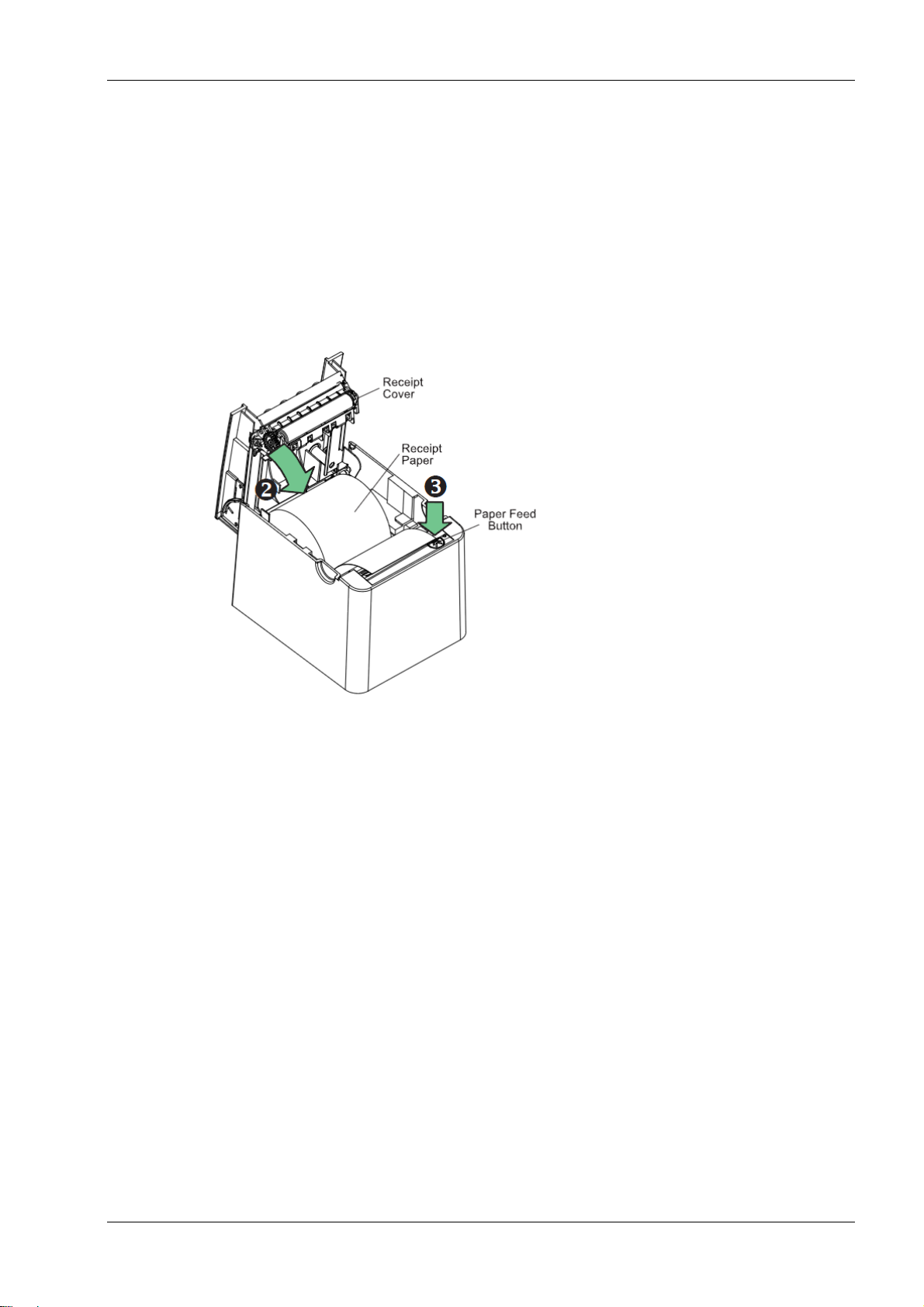
2. Make sure receipt paper is loaded in the rpinter before proceeding. Make sure cover is
closed.
3. Apply power to printer and immediately press and hold the paper feed button until the
configuration printout begins.
The printer beeps, then prints Diagnostics Form I.
Press the paper feed button within two seconds to enter the configuration main menu
The printer prints Diagnostics Form II, followed by the Printer Configuration Menu, and
waits for a main menu selection to be made (see sample printout on page 13; short
clicks are used, except when answering “yes” or validating selection).
4. To communicate with the printer, you will press the paper feed button using either
short or long clicks. Use a long click for “yes” (more than one second) and a short click
for “no.” Follow the printed instructions to make selections.
5. Continue through your menu selections until you are asked, “Save New Parameters?”
Select “Yes.”
Reset the Printer.
Open the receipt cover.
Press and hold the paper feed button while closing the receipt cover.
The diagnostic printout verifies your new settings.
7

TH250 Programmer’s Guide
Baud rate
115200 baud
57600 baud
38400 baud
19200 baud
9600 baud
4800 baud
2400 baud
1200 baud
Parity
No Parity
Even Parity
Odd Parity
Flow control methd
Software (XON/XOFF)
Hardware (DTR/DSR)
Data reception errors
Ignore errors
Print “?”
Alternate DTR/DSR
Enabled
Disabled
USB Driver
Printer Cass
Comm Class
USB NAK
Reject Packets When Error
Accept Packets When Error
Communication interface settings
To change the communication interface settings, enter the configuration menu, select “Set
Communication Interface” from the main menu.
Caution: Be extremely careful changing any of the printer settings to avoid inadvertently changing
other settings that might affect the performance of the printer.
Press the paper feed button as instructed on the configuration menu to select the settings you
want to change.
Note: Press the paper feed button for at least one second to validate the selection.
Setting the RS-232C Serial interface settings
Refer to the section “Configuring the printer”.
Diagnostics modes
To change the the diagnostic modes enter the configuration menu, select “Set Diagnostics Modes”
from the main menu and select one of the following modes:
Normal: normal operating mode of the printer.
Datascope: the receipt printer prints incoming commands and data in hexadecimal format to
help troubleshoot communication problems. There are DataScope modes for both with and
without graphics.
Receipt test: the receipt printer prints all code pages to verify proper printing of the receipt.
Caution: Be extremely careful changing any of the printer settings to avoid inadvertently changing
other settings that might affect the performance of the printer.
Refer to the section “Configuring the printer,” for instructions on how to enter the configuration
menu.
8
TH250 Programmer’s Guide
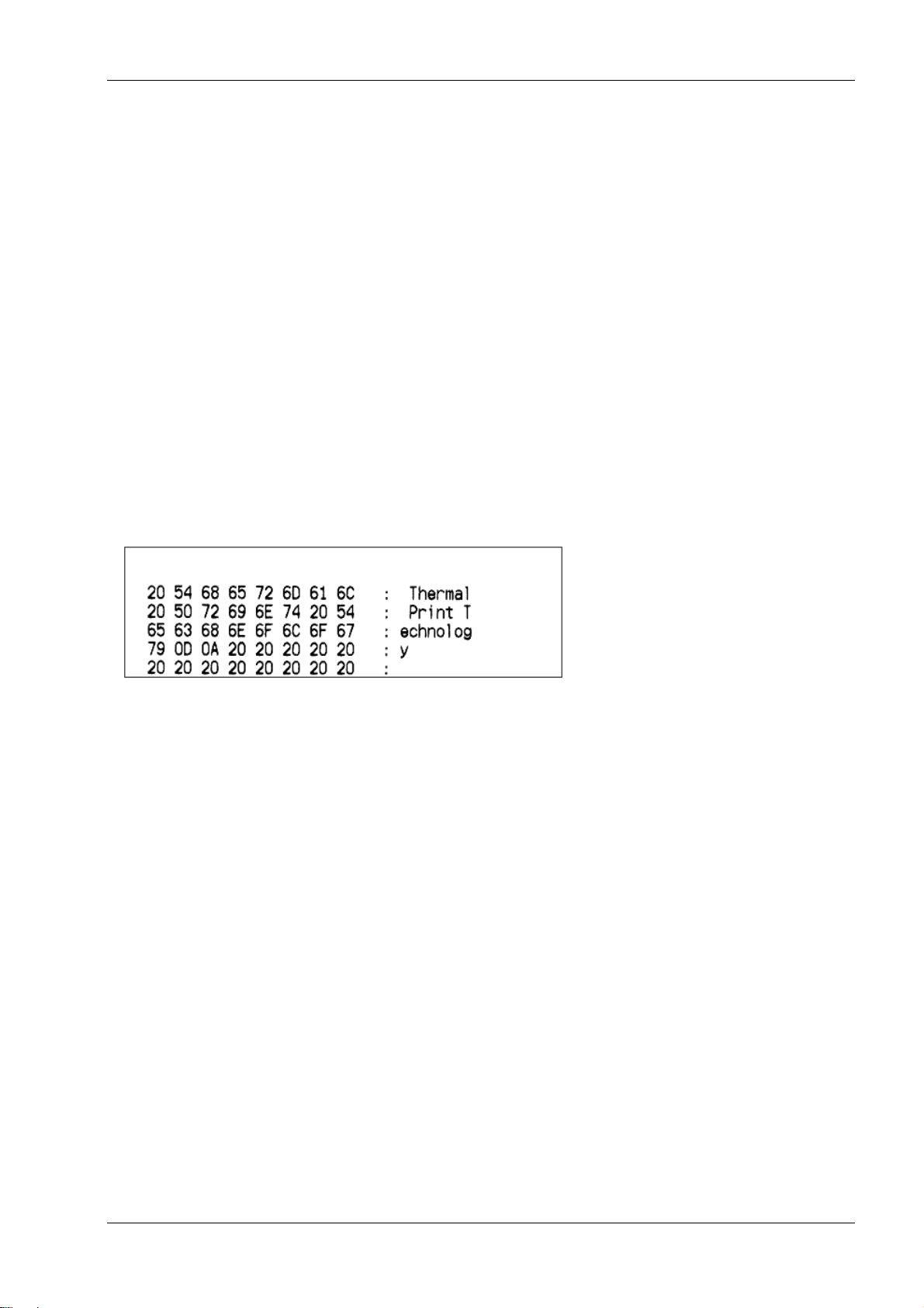
Enable or disable data scope mode
The data scope mode test prints a hexadecimal dump of all data sent to the printer: “1” prints as
hexadecimal 31, “A” as hexadecimal 41 and so on. This helps troubleshoot communication
problems and runs during a normal application (after being enabled through printer configuration).
Note: Data scope mode is usually considered a level 1 diagnostic test.
Data scope mode is enabled and disabled by selecting the “Diagnostics Modes” sub-menu of the
configuration menu. Press the paper feed button as instructed on the “Diagnostics Modes Menu”
to enable or disable the data scope mode test.
Off, normal mode (Data scope mode disabled)
Data scope mode with or without graphics (enabled)
Note: Press the paper feed button for at least one second to validate the selection.
To run the data scope mode:
1. After you have enabled the data scope mode, exit the configuration menu.
2. Run a transaction from the host computer.
All commands and data sent from the host computer will be printed as hexadecimal characters as
shown in the illustration.
To exit the data scope mode:
1. Enter the configuration menu again.
2. Disable the data scope mode.
3. Exit the configuration menu.
The printer is on-line and can communicate normally with the host computer.
Enabling the data scope mode
Refer to the section “Configuring the printer”.
Enable or disable receipt test mode
The receipt test mode verifies proper receipt printing. Receipt test is enabled and disabled by
selecting the “Diagnostics Modes” sub-menu of the configuration menu. See “Configuring the
printer”, for instructions on how to enter the configuration menu.
To run the receipt test mode:
1. Enable the receipt test mode in the configuration menu.
3. Exit the configuration menu.
4. Push the paper feed button. The receipt station prints all code pages and cuts the
receipt.
5. To repeat this test, push the paper feed button again.
9

TH250 Programmer’s Guide
To exit the receipt test mode:
1. Enter the configuration menu again.
2. Disable the receipt test mode.
3. Exit the configuration menu.
The printer is on-line and can again communicate normally with the host computer.
Electronic Journal Datascope Diagnostic
1F 03 18 02 n=1, turn on electronic journal datascope, run time only
1F 03 18 02 n=0, n>1, turn off electronic journal datascope, run time only
1F 03 18 03 n=1, turn on electronic journal datascope, configuration saved over power cycle
1F 03 18 03 n=0, n>1, turn off electronic journal datascope, configuration saved over power cycle
When enabled, “Auto Journal : Datascope” prints on the second diagnostic page.
This diagnostic is for debugging purposes, and should be used only under the direction of customer
support.
Printer emulations
To change the printer emulations settings, enter the configuration menu, select
“Emulation/Software Options” from the main menu and answer “Yes” to “Set printer mode?”
printed on the receipt. This will take you to the instructions for setting the printer emulation.
Caution: Be extremely careful changing any of the printer settings to avoid inadvertently changing
other settings that might affect the performance of the printer.
Press the paper feed button as instructed to select the printer emulation you want.
Native mode
TH210/TH210-2/TH210/TH210-2/A794 emulation
A793 emulation
LEGACY emulation
TH230 emulation
Note: Press the paper feed button for at least one second to validate the selection.
Setting the printer emulation
Refer to the section “Configuring the printer”.
Printer settings and functions
To change the printer settings and functions, enter the configuration menu, select the sub-menu
from the main menu and answer the questions printed on the receipt until you come to the
instructions for selecting the printer settings.
Caution: Be extremely careful changing any of the printer settings to avoid inadvertently changing
other settings that might affect the performance of the printer.
Press the paper feed button as instructed to select the printer settings you want.
Select the emulation/software options sub-menu to set:
Printer Mode
This function is used to set the printer emulation to Native, TH230, TH210/TH210-2/A794, A793 or
Legacy emulation.
10

TH250 Programmer’s Guide
Printer ID mode
This function is used to determine what printer ID value is returned in response to a Transmit
printer ID command (1D 49 n) when the printer is in TH210/TH210-2/A794 emulation mode. The
printer can be configured to send back the ID of the TH250, TH210/TH210-2/A794, A793 or
Application Compatible Escape Command systems.
Default lines per inch
This function allows you to set the default for lines per inch to:
8.13 lines per inch
7.52 lines per inch
6.77 lines per inch
6.00 lines per inch
Carriage return usage
This function allows the printer to ignore or use the carriage return (hexadecimal 0D) command
depending on the application. Some applications expect the command to be ignored while others
use the command as a print command.
Code 128 Check Digit
Enables or disables the calculation of the check digit.
Default font
Sets the default for monochrome, two-color, and LEGACY emulations.
Font size
Allows user to set font size for the emulation being used.
Journal Print
Enables or disables operator action.
Select the hardware options sub-menu to set:
Color density
Adjusts printhead energy level to darken color printing or adjust for paper variations. When printer
prints high-density color print lines (text or graphics), it automatically slows down. Factory setting
is 100%.
WARNING: Choose a color density setting no higher than necessary to achieve acceptable color
print density. Failure to observe this rule may result in a printer service call and may void the
printer warranty. Running at a higher energy level will reduce the printhead life. Consult your
Wincor Nixdorf technical support specialist if you have questions.
Print density (monochrome papers only)
Adjusts printhead energy level to darken printout or adjust for paper variations. When printer
prints high-density print lines (text or graphics), it automatically slows down. Factory setting for
the TH250 is 100%.
Note: when printer is set to color paper, Print Density adjusts the overall darkness for both color
and monochrome.
WARNING: Choose a print density setting no higher than necessary to achieve acceptable print
density. Failure to observe this rule may result in a printer service call and may void the printer
warranty. Running at a higher energy level will reduce the printhead life. Consult your Wincor
Nixdorf technical support specialist if you have questions.
Power supply level (Max power)
You can choose from these power settings to match the power supply:
Auto (for Wincor Nixdorf power supplies)
55W
75W
11

TH250 Programmer’s Guide
90W
Partial cut distance
Allows the user to set the distance that the knife will cut across a receipt in 5 step increments
between 110-160.
Fine partial cut steps
Allows the user to set the amount of extra steps the knife will cut across a receipt, between 0 and
4.
Paper low sensor
Senses when the paper roll is getting low on paper.
See troubleshooting section: “Receipt paper is low” in the User Manual.
Paper low threshold extension
Allows the user to set the amount of footage for the extension in 5-foot (1.5 meters) increments
between -10 and 20 feet (-3 meters and 6 meters).
Setting the printer functions and settings
Refer to the section “Configuring the printer”.
Select the paper type sub-menu to set:
Paper Type Name
Sets the printer to optimum performance for paper being used. This can also be done through the
command 1D 81 m n. See the following chapter for command usage.
Available paper types may vary. Refer to our website, www.wincor-nixdorf.com, for an up-to-date
list of qualified paper manufacturers. Currently there are 3 types:
0 = monochrome
4 = two-color (blue/black)
5 = two-color, (red/black or green/black)
Select the firmware features sub-menu to set:
Paper selection lockout
Beep after knife cut
Cash drawer open after knife cut
Energy-savings timeout value
Allows the user to enable and set the time-out value to 15, 30, 60, 120, or 240 minutes, or to
disable the feature.
Print quality level
Allows the user to set the print quality to speed (350mm/s), balanced (300mm/s), or quality
(250mm/s).
12

TH250 Programmer’s Guide
Command
Description
Difference between previous product and new
product emulation mode
15n
Feed n dot rows
This command will move the paper on the receipt
in n/203 inch steps instead of n/152 inch steps.
16 n
Add n extra dot rows
The dot rows will be measured in n/203 inches
versus n/152 inches.
1B 20 n
Set right-side
character spacing
This command sets the right side spacing to “n”
horizontal motion units. By default, these units
are in terms of 1/203 inches versus 1/152 inches.
1B 24 n1
n2
Set absolute starting
position
For graphics commands, the position is scaled to
best match A793. In text mode, the equivalent
character position is calculated.
1B 26 s c1
c2 n1 d1
...nn dn]
Define user-defined
character set
Since the dots on the TH250 printhead are
smaller, user defined characters that were used
on the previous printers will appear smaller on
the TH250 printer.
1B 2A m
n1 n2
d1...dn
Select bit image
mode
In A793 emulation mode, graphics are scaled to
best match the size of the graphic in the A793
printer.
1B 33 n
Set line spacing
This command uses n in terms of n/360 inches.
Since the A793 had a fundamental step of 1/152
Programming the Printer
Overview of commands
Commands control all operations and functions of the printer. This includes selecting the size and
placement of characters and graphics on the receipt to feeding and cutting the paper. The
programming commands have been organized, in order of hexadecimal code within functional
groups. For this reason, “related” commands may not be listed adjacent to one another.
The operation of various printers may be emulated by the commands, including the following:
Native
A793/TH210/TH210-2/A794
TH230
LEGACY
Any of the commands may be used in any combination to program a host computer to
communicate with the printer (unless otherwise noted).
Some commands listed and described here may not be implemented and are identified as “not
implemented.” If received, they are ignored and not sent to the print buffer as data.
Any nonlegal commands have their parameter sent to the print buffer as data.
Comparison to A793
The following table details the list of commands whose behavior differs between the A793,
TH210/TH210-2/A794, and TH250 because of the physical differences of a 6 dots/mm head (A793)
versus an 8 dots/mm head (TH210/TH210-2/A794 and TH250).
13
TH250 Programmer’s Guide
Command
Description
Difference between previous product and new
product emulation mode
inch and the TH250 has a fundamental step of
1/203 inch, the actual line spacing will not exactly
match the requested spacing.
1B 4A n
Print and feed paper
This command uses n in terms of n/360 inches.
Since the A793 had a fundamental step of 1/152
inch and the TH250 has a fundamental step of
1/203 inch, the actual line spacing will not exactly
match the requested spacing.
1B 59 n1
n2 d1...dn
Select doubledensity graphics
In A793 emulation mode, the printer scales the
graphics to provide the best match.
1B 5C n1
n2
Set relative print
position
The parameter to this command is in units of
dots.
However, the command moves and aligns to
character positions. In A793 emulation mode, this
command calculates how many character
positions to move based on the A793 character
width in dots (10) versus the TH250 (13).
1B 61 n
Select justification
This command does true dot resolution
alignment for centering versus character-aligned
centering.
1D 2A n1
n2
d1...dn]
Define downloaded
bit image
In A793 emulation mode, this command scales
the incoming data to provide a best match to the
size of the image as it printed on A793.
1D 2F m
Print downloaded
bit image
In A793 emulation mode, this command scales
the incoming data to provide a best match to the
size of the image as it printed on A793.
14
TH250 Programmer’s Guide
Color interpreted commands
Hexadecimal
ASCII
Description
1B 72 m
ESC r m
Set current color
1D A0 nl nh
1D GS
Set temporary maximum target speed
1D 23 n
GS # n
Select current logo
1D 42 n
GS B n
Select or cancel white/black reverse print
mode
1D 2A n1 n2 d1 dm
GS * n1 n2 d1 – dm
Define downloaded bit image
1D 2F m
GS / m
Print downloaded bit image
1D 81 m n
GS 0x81 m n
Set paper type
1D 82 n1 n72
GS 0x82 n1– n72
Print raster monochrome graphics
1D 83 n1 n144
GS 0x83 n1– n144
Print raster color graphics
1D 84 n m n1 n2 d1 dx
GS 0x84 n m n1 n2
d1 dx
Download logo image
1D 85 m n
GS 0x85 m n
Reverse color text mode (two-color)
1D 86 m
GS 0x86 m
Monochrome shade mode
1D 87 m
GS 0x87 m
Color shade mode
1D 89 n m
GS 0x89 n m
Logo print with color plane swap
1D 8B n m o
GS 0x8B n m o
Apply shading to logo
1D 8C n m
GS 0x8C n m
Merge watermark mode
1D 8D n m
GS 0x8D n m
Text strike through mode
1D 90 m x y o p q
GS 0x8A m x y o p
q
Form and print real time surround
graphic
1D 91 n
GS 0x91 n
Save graphics buffer as logo
1D 92 n
GS 0x92 n
Background logo print mode
1D 97 m n
GS 0x87 m n
User storage status
1D 99 l m n o
US
Apply margin message mode
1D 9A n m o
GS 0x9A n m o
Shade and store logo
1D 9B m n
GS
Logo print with knife cut
1F 03 16 05 n
US
Set interpretation of “Set current color”
command
Two-color commands (comparison TH210 to TH250)
The following table details the list of commands that have been added for two-color functionality
or existing commands that have been altered by the addition of two-color capacity.
15
TH250 Programmer’s Guide
Standard
Rotated
Italic
Compressed
Underlined
Strike-through
Double-high
Bold
Scaled
Double-wide
Reverse
Shading
Upside-down
Rotated
Italic
Standard
Compressed
Characters per inch: 15.6
Characters per inch: 20.3
Characters per line: 44
Characters per line: 56
Cell size:
13 x 24 dots (default font)
13 x 27 dots (Tall fonts)
13 x 18 dots (paper-saving font)
Cell size:
10 x 24 dots (default font)
10 x 27 dots (Tall fonts)
10 x 18 dots (paper-saving font)
576 dots (addressable) @ 8
dots/mm, centered on 80mm
Top margin to manual tear-off:
17.8mm (0.70 inches)
Standard mode: minimum
margins: 2.0mm (.079 inches)
Top margin to knife cut: 19.0mm
(0.75 inches)
Character appearance
The appearance of text can be changed using the following print modes:
Width specifications
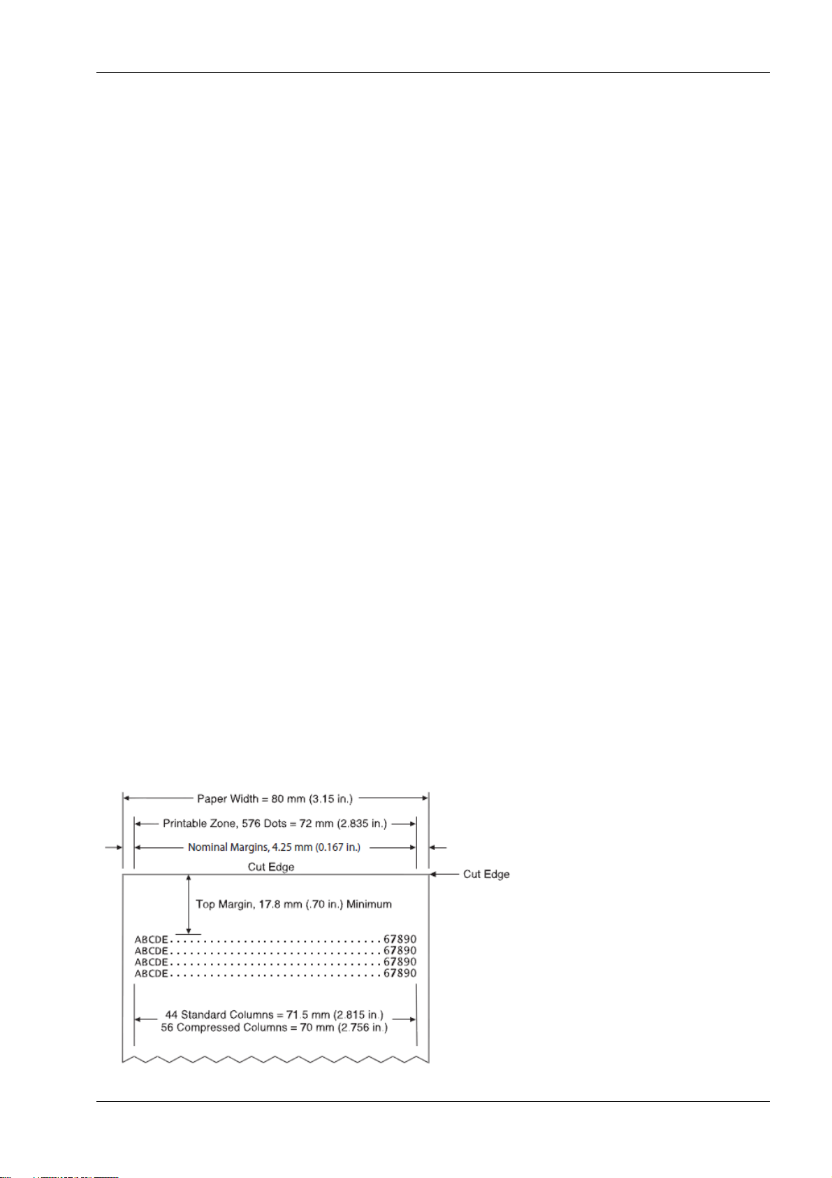
Print zones
Print zones for 80mm paper
Specifications of print zone for 80mm paper:
16
TH250 Programmer’s Guide
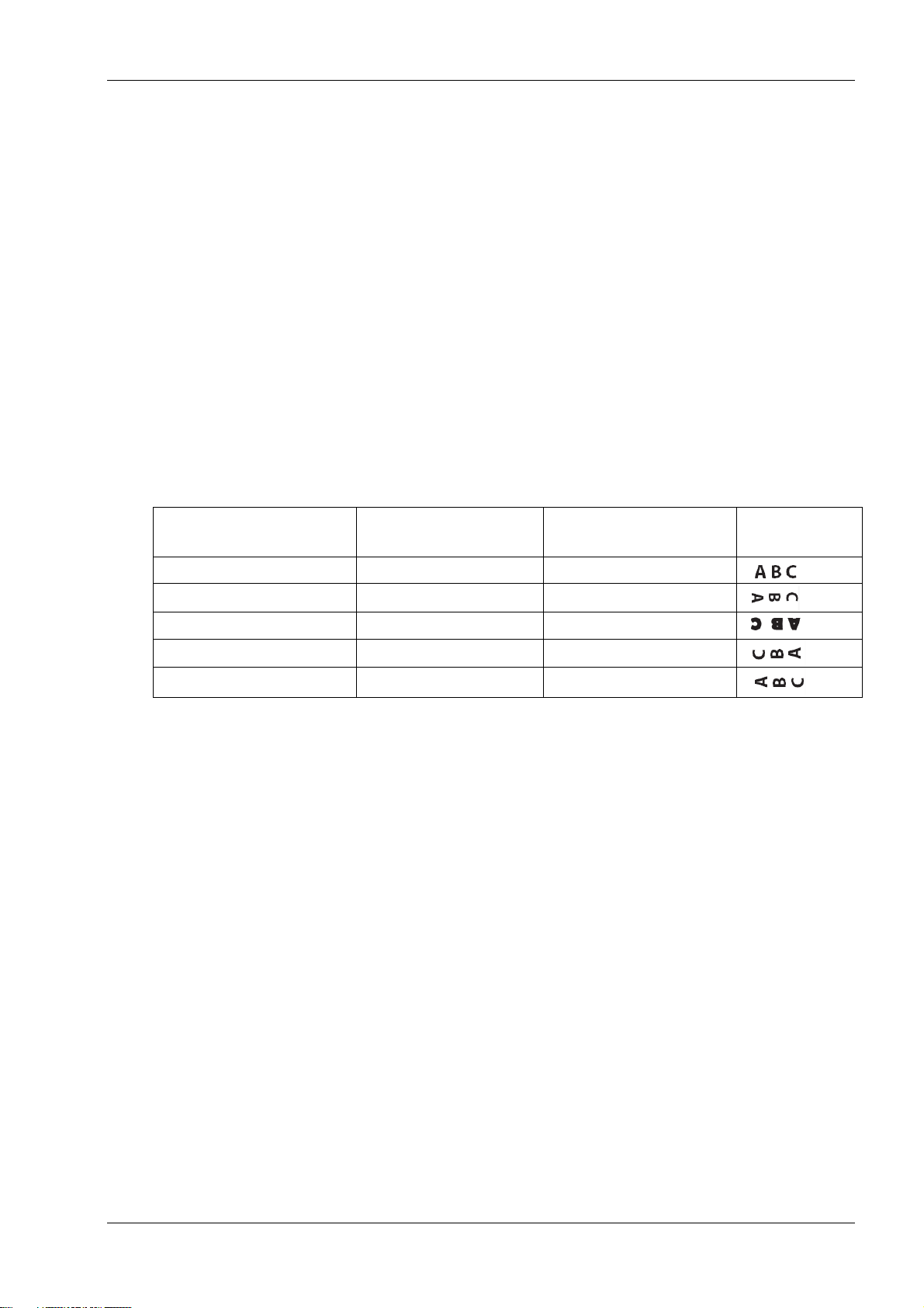
Upside down (1B 7B n)
Rotated CW (1B 56 n)
Rotated CCW (1B 12)
Resulting
output
Canceled
Canceled
Cleared
Canceled
Set
X
Set
Canceled
X
Set
Set
X
X X Set
Note: The application centers 44 standard character cells (13 X 24 dots), or 56 compressed
character cells (10 X 24 dots), or 576 addressable bits of graphics across an 80mm wide receipt.
Minimum print line height is 24 dots for text or graphics. Standard print line spacing is 27 dots (i.e.,
3 extra row dots).
The TH250 Series adds a 27 dot high font, so standard print spacing is 30 dots.
The TH250 Series paper-saving feature adds a 18 dot high font and reduces extra dot rows to 2, so
standard print spacing is 20 dots.
Rotated printing commands
Three commands control the rotation of printing. The table shows the combinations of set/cancel
upside down print, set/ cancel rotated print (clockwise), and rotated print (counterclockwise).
Rotated clockwise and rotated counterclockwise print commands are mutually exclusive: the
setting of the last received command is effective. Unintended consequences may result when
rotated clockwise is mixed with other commands
The samples of the print show only the normal-size characters. Double-wide and double-high
characters are printed in the same orientation. They may also be mixed on the same line.
Note: The following print modes cannot be mixed on the same line:
Right-side up and upside-down
17
TH250 Programmer’s Guide
Emulation
mode
LPI
options
Font(s)
options
Font
size
Default
LPI
Default
EDR
Comments
Native,
6.00,
6.77,
7.52,
8.13
Standard
13X24
7.52
3
Default setup for
monochrome paper
TH230
Tall
13X27
6.77
3
Emulation
2-color
13X27
6.77
3
Default setup for twocolor paper
Papersaving
13X18
10.15
3
TH210/
A793/A794
emulation
6.00,
7.52,
8.13
Standard
13X24
7.52
3
LEGACY
emulation
6.00
Tall 13X27
6.00
7
Default setup for
Escape Commands
Standard
13X24
6.00
10
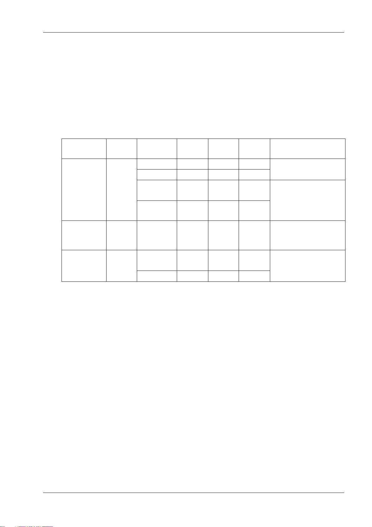
Emulation modes
The Wincor Nixdorf TH250 Series printer may be operated in a number of different emulation
modes. However, printing characteristics and defaults may differ, depending on the desired mode.
For instance, two-color paper commands and features are available only in TH250 native mode.
Print setup in emulation modes
Refer to the chart below for defaults and allowed printing options in each emulation mode.
The following list clarifies how the TH250 printer will behave in each emulation mode:
Two-color paper commands and features are supported only in native mode.
If the paper type is changed using the 0x1D 0x81 command, the font and default lines per inch
(LPI) will be setup as in the table above.
If only the font is changed, the default LPI will automatically be changed as in the table above.
If emulation is switched to LEGACY, Native, TH230, TH210/TH210-2/A794 or A793
emulation(s), the paper type will automatically be changed to monochrome paper, and the
font and LPI will be changed as in the table above.
If emulation is switched from any emulation to native or TH230, the font and LPI will remain
unchanged because the Native and TH230 modes supports all font and LPI options offered in
the emulation modes.
The “Set Default LPI” option in the configuration menu is not offered in LEGACY emulation
mode. The LPI is set at 6.00.
18
TH250 Programmer’s Guide
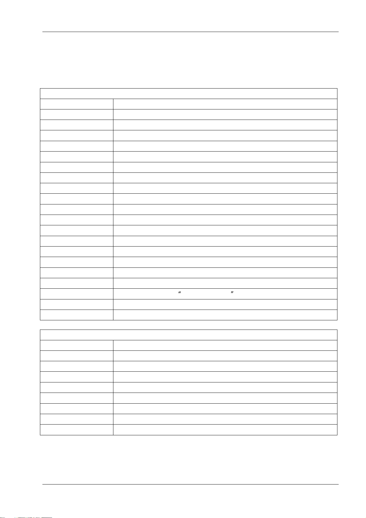
Printer actions
Code (hexadecimal)
Command
10
Clear printer
19
Perform full knife cut (or code 1B 69)
1A
Perform partial knife cut (or code 1B 6D)
1B 07
Generate tone
1B 3D n
Select peripheral device (for multi-drop)
1B 40
Initialize printer
1B 63 34 n
Select sensors to stop printing
1B 63 35 n
Enable or disable panel button
1B 69
Perform full knife cut (or code 19)
1B 6D
Perform partial knife cut (or code 1A)
1B 70 n p1 p2
Generate pulse to open cash drawer
1B 72 m
Set current color
1F 03 3C ll hh
Set timeout value for low-power idle state
1F 70
Set printer into low-power idle state
1D 56 m
Select cut mode and cut paper (or code 1D 56 m n)
1D 56 m n
Select cut mode and cut paper (or code 1D 56 m)
1D 81 m n
Set paper type (for two-color printing)
1F 03 16 05 n
Set interpretation of Set current color command
1F 03 4E n1 n2
Port Idle Timeout
1F 74
Print test form
Print and paper feed
Code (hexadecimal)
Command
0A
Print and feed paper one line
0D
Print and carriage return
14n
Feed n print lines
15 n
Feed n dot rows
16 n
Add n extra dot rows
17
Print
1B 4A n
Print and feed paper
1B 64 n
Print and feed n lines
Programming Commands
Commands listed by function
19

TH250 Programmer’s Guide
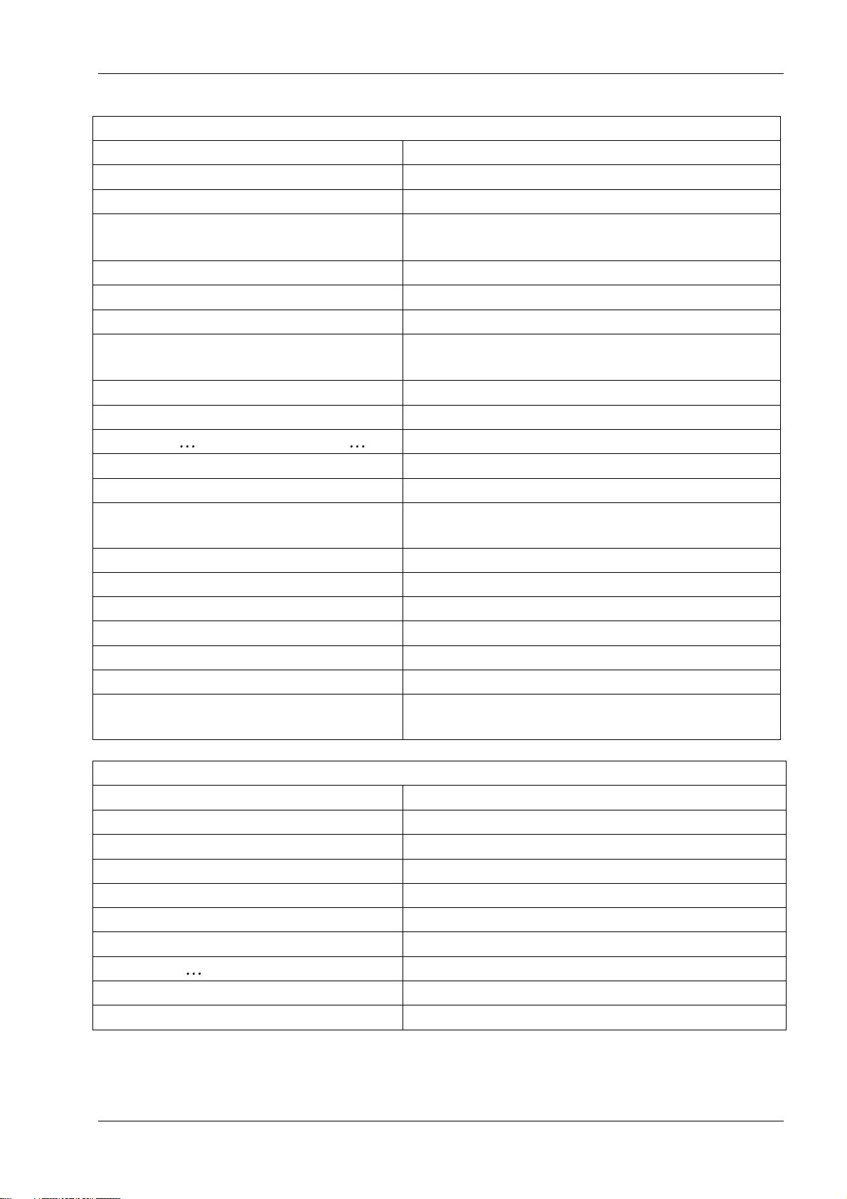
Vertical and horizontal positioning
Code (hexadecimal)
Command
09
Horizontal tab
1B 14 n
Set column
1B 24 nL nH
Set absolute starting position
1B 32
Set vertical line spacing to 1/6 inch
1B 33 n
Set vertical line spacing
1B 44 n1...nk 00
Set horizontal tab positions
1B 5C n1 n2
Set relative print position
1B 61 n
Select justification
1D 4C nL nH
Set left margin
1D 50 x y
Set horizontal and vertical minimum motion units
1D 57 nL nH
Set printing area width
Text characteristics
Code (hexadecimal)
Command
12
Select double-wide characters
13
Select single-wide characters
1B 12
Select 90 degree counter-clockwise rotated print
1B 16 n
Select pitch (column width)
1B 20 n
Set right-side character spacing
1B 21 n
Select print mode
1B 25 n
Select or cancel user-defined character set
1B 26 s c1 c2
Define user-defined character set
1B 2D n
Select or cancel underline mode
1B 3A 30 30 30
Copy character set from ROM to RAM
1B 3F n
Cancel user-defined character
1B 45 n
Select or cancel emphasized mode
1B 47 n
Select or cancel double-strike
1B 49 n
Select or cancel italic print
1B 52 n
Select international character code
1B 56 n
Select or cancel 90 degree clockwise rotated print
1B 74 n
Select international character set
1B 7B n
Select or cancel upside-down print mode
1D 21 n
Select character size
1D 42 n
Select or cancel white/black reverse print mode
1D 62 n
Set smoothing
1D 85 m n
Reverse color text mode (two-color)
1D 8D n m
Text strike-through mode
1D F0 01 n
Select font ID number
1D F0 02 ns
Select font tyle number
20

TH250 Programmer’s Guide
Text characteristics
Code (hexadecimal)
Command
1D F0 03
Save font ID number as default font at power up
1D F0 80
Download font
1D F0 C0 02
Download font list
1F 03 45 FSID
Configure use of font set over power cycles
1F 03 46 n
Configure line spacing
1F 05 n
Select superscript or subscript modes
1F 26 s c1 c2
Define extended user-defined character set
1F 69 n
Select active user-defined character set
1D F0 20 nn
Get double-byte font CRC (font ID)
1D F0 21 nn mm
Get double-byte font CRC (font ID and font style)
Text characteristics
Code (hexadecimal)
Command
12
Select double-wide characters
13
Select single-wide characters
1B 12
Select 90 degree counter-clockwise rotated print
1B 16 n
Select pitch (column width)
1B 20 n
Set right-side character spacing
1B 21 n
Select print mode
1B 25 n
Select or cancel user-defined character set
1B 26 s c1 c2
Define user-defined character set
1B 2D n
Select or cancel underline mode
1B 3A 30 30 30
Copy character set from ROM to RAM
1B 3F n
Cancel user-defined character
1B 45 n
Select or cancel emphasized mode
1B 47 n
Select or cancel double-strike
1B 49 n
Select or cancel italic print
1B 52 n
Select international character code
1B 56 n
Select or cancel 90 degree clockwise rotated print
1B 74 n
Select international character set
1B 7B n
Select or cancel upside-down print mode
1D 21 n
Select character size
1D 42 n
Select or cancel white/black reverse print mode
1D 62 n
Set smoothing
1D 85 m n
Reverse color text mode (two-color)
1D 8D n m
Text strike-through mode
1D F0 01 n
Select font ID number
1D F0 02 n
Select font style number
1D F0 03
Save font ID number as default font at power up
21

TH250 Programmer’s Guide
Text characteristics
Code (hexadecimal)
Command
1D F0 80
Download font
1D F0 C0 02
Download font list
1F 03 45 FSID
Configure use of font set over power cycles
1F 03 46 n
Configure line spacing
1F 05 n
Select superscript or subscript modes
1F 26 s c1 c2
Define extended user-defined character set
1F 69 n
Select active user-defined character set
1D F0 20 nn
Get double-byte font CRC (font ID)
1D F0 21 nn mm
Get double-byte font CRC (font ID and font style)
Graphics
Code (hexadecimal)
Command
11 n1 . . . n72
Print raster graphics
1B (+*.BMP file)
Download BMP logo
1B 2A m n1 n2 d1 dn
Select bit image mode
1B 2E m n rL rH d1 dn
Print advanced raster graphics
1B 4B n1 n2 d1 dn
Select single-density graphics
1B 59 n1 n2 d1 dn
Select double-density graphics
1C 70 n m
Print flash logo
1C 71 n . . . .
Define flash logos
1D 23 n
Select the current logo (downloaded bit image)
1D 2A n1 n2 d1 dn
Define downloaded bit image
1D 2F m
Print downloaded bit image
1D 82 n1 n72
Print raster monochrome graphics
1D 83 n1 n144
Print raster color graphics
1D 84 m n1 n2 d1 dx
Download logo image
1D 8B n m o
Apply shading to logo
1D 86 m
Monochrome shade mode
1D 87 m
Color shade mode
1D 89 n m
Logo print with color plane swap
1D 8C n m
Merge watermark mode
1D 90 m x y o p q
Form and merge real time surround graphic
1D 91 n
Save graphics buffer as logo
1D 92 n
Background logo print mode
1D 99 l m n o
Apply margin message mode
1D 9A n m o
Shade and store logo
1D 9B m n
Logo print with knife cut
1D A0 nl nh
Set temporary max target speed
1F 04 n
Convert 6-dots/mm bitmap to 8 dots/mm bitmap
22

TH250 Programmer’s Guide
Graphics
Code (hexadecimal)
Command
1F 7B n
Enable constant speed logos
Status
Batch mode
Code (hexadecimal)
Command
1B 75 0
Transmit peripheral device status (RS-232C printers only)
1B 76
Transmit paper sensor status
1D 49 n
Transmit printer ID
1D 49 40 27
Transmit printer model number
1D 72 n
Transmit status
1F 56
Send printer software version
Real time
Code (hexadecimal)
Command
10 04 n
Real time status transmission (DLE sequence)
10 05 n
Real time request to printer (DLE sequence)
1D 03 n
Real time request to printer (GS sequence)
1D 04 n
Real time status transmission (GS sequence)
1D 05
Real time printer status transmission
1F 7A
Real time commands disabled
Automatic status back / Unsolicited status mode
Code (hexadecimal)
Command
1D 61 n
Enable/disable Automatic Status Back (ASB)
1D 61 n
Select or cancel unsolicited status mode
23
TH250 Programmer’s Guide
Bar codes
Code (hexadecimal)
Command
1D 48 n
Select printing position for HRI characters
1D 66 n
Select pitch for HRI characters
1D 28 6B 04 00
00 31 41 n1 n2
Select model for QR Code
1D 28 6B 03 00 31 43 n
Set size of module for QR Code
1D 28 6B 03 00 31 44 m
Set data parsing mode for QR Code
1D 28 6B 03 00 31 45 n
Select error correction level for QR Code
1D 28 6B qL qH
31 50 30 f1 ... fk
Store symbol data for QR Code
1D 28 6B 03 00 31 51 30
Print symbol data for QR Code
1D 68 n
Select bar code height
1D 6B m d1 dk 00 or 1D 6B m n d1 dn
Print bar code
1D 6B FF n
Print Multiple Barcodes
1D 6B n d1... 00
Print GSI Databar (formerly RSS), null terminated
1D 6B m n L n H d1... dn
Print GSI Databar (formerly RSS), data length
specified
1D 70 a b c d e f
Select PDF 417 parameters
1D 71 a b c d e f L f H
Set GSI Databar (formerly RSS) parameters
1D 77 n
Select bar code width
1D 28 6B 05 00 36 42 m d1 d1
Set DataMatrix parameters
1D 28 6B 05 00 36 43 n
Set DataMatrix module size
1D 28 6B pL pH 36 50 30 d1...dk
Store DataMatrix data in symbol storage area
1D 28 6B 03 00 36 54 30
Print DataMatrix symbol data in the symbol storage
area
Page mode
Code (hexadecimal)
Command
0C
Print and return to standard mode
18
Cancel print data in page mode
1B 0C
Print data in page mode
1B 4C
Select page mode
1B 53
Select standard mode
1B 54 n
Select print direction in page mode
1B 57 n1, n2 n8
Set print area in page mode
1D 24 nL nH
Set absolute vertical print position in page mode
1D 5C nL nH
Set relative vertical print position in page mode
24
TH250 Programmer’s Guide
Macros
Code (hexadecimal)
Command
1D 3A
Select or cancel macro definition
1D 5E r t m
Execute macro
User data storage
Code (hexadecimal)
Command
1B 27 m a0 a1 a2 d1…dm
Write to user data storage
1B 34 m a0 a1 a2
Read from user data storage
1D 22 n
Select memory type (SRAM/flash) where to save
logos or user-defined fonts
1D 22 55 n1 n2
Flash memory user sectors allocation
1D 22 60 n1
Flash object area pack
1D 22 61 n1 n2 (n3)
Flash object delete
1D 22 80
Expanded flash memory allocation
1D 22 81 n
Select flash area for storing logos and user-defined
characters
1D 22 90 n
Return flash area size
1D 40 n
Erase user flash sector
1D 97 m n
User storage status
1D F0 10 n
Lock permanent flash area
Flash download
Code (hexadecimal)
Command
1B 5B 7D
Switch to flash download mode
1D 0E
Erase all flash contents except boot sector
1D 0F
Return main program flash CRC
1D 11 00 00 00 00 d1 dn
Download Application
1D FF
Reset firmware
Ethernet setup commands
Code (hexadecimal)
Command
1B 5B 7D
Switch to flash download (boot mode)
1F 08 00
Restore default settings
1F 08 01 n1 n2 n3 n4
Set IP address
1F 08 02 n1 n2 n3 n4
Set net mask
1F 08 03 n1 n2 n3 n4
Set gateway
1F 08 04 n1 n2
Set raw TCPIP port
1F 08 08 n1
DHCP
1F 08 09 n1
Inactivity timeout
1F 08 0A n1
Keep-alive pings (arps)
25
 Loading...