

Wincor Nixdorf ND69 User Manual

ND69
Modular POS Printer
ND69
User Guide

ND69
Modular POS Printer
User Guide
Edition July 2000

Copyright © Wincor Nixdorf GmbH & Co. KG,2000
The reproduction, transmission or use of this document or its contents is not permitted
without express authority.
Offenders will be liable for damages.
All rights, including rights created by patent grant or registration of a utility model or design, are reserved.
Delivery subject to availability; technical modifications possible.
BEETLE ® is a registered trademark of the Wincor Nixdorf GmbH & Co. KG (WN).
MS-DOS ® and Microsoft ® are registered trademarks of the Microsoft Corporation.
SINIX ® is a registered trademark of the Wincor Nixdorf GmbH & Co. KG .
UNIX ® is a registered trademark of the X/Open Company Ltd.

Contents
Manufacturer’s Certification..............................................................................................1
General Licence...................................................................................................................1
FCC-Class A Declaration .....................................................................................................1
Tested Safety.......................................................................................................................1
Important Notes....................................................................................................................2
Introduction ........................................................................................................................3
About this manual ................................................................................................................3
Care of the ND69 .................................................................................................................3
Recycling the ND69 POS Printer .........................................................................................4
Installation ..........................................................................................................................5
Before Switching On ............................................................................................................5
Unpacking and Checking the Scope of Supply...............................................................5
Setting up the Device......................................................................................................5
Cabling of the ND69........................................................................................................5
Securing the Data Communication Cable.......................................................................6
Connecting to the Mains Power Supply..........................................................................6
Disconnecting Cables .....................................................................................................7
Connecting to the POS System ...........................................................................................8
DIP Switches........................................................................................................................8
Compatibility.......................................................................................................................10
Data Retention and Loss When Opening Cover...........................................................11
Data Retention and Loss at Paper End ........................................................................11
Connecting Peripherals......................................................................................................11
Cash Drawer (CASHDRW)...........................................................................................11
Customer Display .........................................................................................................12
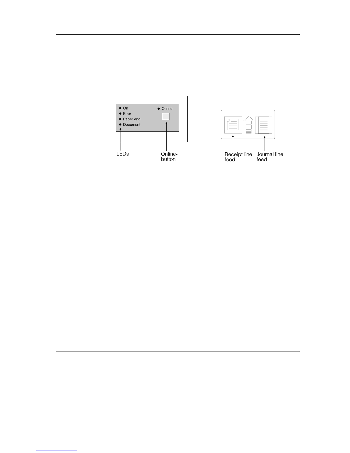
The Operator Control Panel...............................................................................................13
Online Button ................................................................................................................13
Receipt Line Feed Button..............................................................................................13
Journal Line Feed Button..............................................................................................14
LEDs .............................................................................................................................14
Self Test .............................................................................................................................15
Hexadecimal Dump Function.............................................................................................18

Operation of the ND69 POS printer ............................................................................... 19
Inserting the Spacers ........................................................................................................ 20
Document Processing....................................................................................................... 21
Changing the Receipt and Journal Paper ......................................................................... 22
Green Paper Feed Button............................................................................................ 23
Changing the Receipt Roll................................................................................................. 23
Remove the remaining receipt paper ........................................................................... 24
Inserting the Receipt Roll............................................................................................. 25
Changing the Journal Roll................................................................................................. 27
Removing the Journal Paper........................................................................................ 27
Inserting the Journal Paper.......................................................................................... 29
Changing the Ribbon Cassette ......................................................................................... 32
Clearing Paper Jams......................................................................................................... 35
Replacing the Print Head .................................................................................................. 37
Control Sequences of the ND69 Printer........................................................................ 39
Notation of the Command Description .............................................................................. 41
Description of the Control Characters and Sequences ..................................................... 42
Character Set ....................................................................................................................78
Appendix.......................................................................................................................... 80
Technical Data .................................................................................................................. 80
Paper Specifications.......................................................................................................... 82
Receipt/Journal paper (single-ply)................................................................................ 82
Document Paper .......................................................................................................... 82
Useable Surface........................................................................................................... 83
Print range (backside Receipt/Journal)........................................................................ 84
Interfaces........................................................................................................................... 85
Parallel Interface to the System ................................................................................... 85
Serial Interface to the System...................................................................................... 88
Connecting Cable......................................................................................................... 89
Serial Interface to the Customer Display...................................................................... 90
Cash Drawer Connection............................................................................................. 92
DIP Switches.....................................................................................................................92
Possible Problems ............................................................................................................ 94
Cleaning Instructions......................................................................................................... 96
Cleaning the Transport Axles of the Print Head........................................................... 96
Cleaning the Printing Mechanism ................................................................................ 96
Glossary............................................................................................................................ 97

Manufacturer’s Certification
General Licence
The device complies with the requirements of the EEC directives
89/336/EEC with regard to “Electromagnetic compatibility” and
73/23/EEC “Low Voltage Directive”. Therefore, you will find the
CE mark on the device or packaging.
FCC-Class A Declaration
This equipment has been tested and found to comply with the limits for a Class A digital
device, pursuant to part 15 of the FCC Rules. These limits are designed to provide
reasonable protection against harmful interference when the equipment is operated in a
commercial environment. This equipment generates, uses, and can radiate radio
frequency energy and, if not installed and used in accordance with the instruction manual,
may cause harmful interference to radio communications.
Operation of this equipment in a residential area is likely to cause harmful interference in
which case the user will be required to correct the interference at his own expense.
Le présent appareil numériquenegénère pas de bruits radioélectriques dépassant les
limites applicable aux appareils numériques de la “Class A” prescrites dans le Règlement
sur le brouillage radioélectrique édicté par le ministère des Communications du Canada.
Tested Safety
The ND69 has been provided with the symbol for
“Tested Safety”.Inaddition,theND69hasreceivedthe
cUL symbol, the UL/CSA symbol and the CE symbol.
GB - 1

Important Notes
ImportantNotesManufacturer’sCer tification
The modular ND69 POS Printer complies with the relevant safety regulations for dataprocessing equipment, including electronic office machines, for use in the office
environment. Should you have any doubts about the permissibility of installation in a
certain environment, please contact Wincor Nixdorf Customer Service.
If the device is brought into the room of operation from a cold environment, dewfall
(condensation) can occur. Before starting up, the device must be completely dry; it is
therefore necessary to observe an acclimatization period of at least two hours.
This device is equipped with a safety-tested power cable and may be connected only
toagroundedplugsocket.
When setting up the device, ensure that there is easy access to the power socket on
the device and/or to the grounded-contact mains socket.
Position the leads and cables so that no one steps on or trips over them.
To disconnect the device from the supply voltage completely, switch off the device
and disconnect the power plug.
Make sure that no objects (for example, paper clips) or liquids get into the inside of
the device. Electric shocks or short circuits can be caused in this way.
Never plug or unplug data communication lines during thunderstorms.
Protect the ND69 from vibrations, dust, moisture and heat.
The device should only be transported in its original packing (protection against
knocks and bumps).
In emergencies (e.g. damaged housing or power cable, entry of liquid or foreign bo-
dies), the device must be switched off and unplugged immediately, and Wincor Nixdorf Customer Service should be called.
Always dispose of used parts, such as printer ribbons, in an environmentally safe
manner.
The device may be repaired by authorized qualified personnel only. Unauthorized
opening of the device and inexpertly carried out repairs will not only seriously
jeopardize the safety of the user, but also lead to cancellation of all warranty and
liability agreements.
Important Notes Manufacturer’s Certification
GB - 2

Introduction
The modular ND69 Pin Printer is a high-performance and economical POS system printer
of receipts, journals and documents, which is easy to install (plug-in-system), easy to use,
and which requires a minimum of space. The integrated autoranging means that the
printer requires no special alterations for use in specific countries. The ND69 has no
troubleevenwithlargereceipts;itcanprintreceiptsofuptoA4insize-quicklyand
easily.
The printer is equipped with connections for a customer display and a cash drawer, which
means that the number of interfaces on the system unit of your POS can be reduced.
Because the industrial standards have been employed - system interfaces V.24 and
Centronics - the investment you have made is protected even when you make use of a
different POS system. With its performance, the ND69 is an essential supplement to your
entire point of sale system!
About this manual
Aboutthis manual
This manual provides you with all the information you require to ensure that your ND69
Printer operates without a single hitch. It tells you everything you need to do before
switching on the printer, how to connect additional devices, and which adjustments might
be necessary from time to time to ensure that your ND69 operates reliably. We therefore
ask you to read the appropriate sections of this manual before making use of your printer.
Care of the ND69
Clean your printer at regular intervals with a suitable surface cleaner. Make sure that the
power plug is disconnected and that no moisture finds its way into the device.
Before cleaning the printer, read the notes on cleaning in the appendix.
GB - 3

Recycling the ND69 POS Printer
RecyclingIntroduction
Environmental protection does not begin
when it is time to dispose of the technical
device; it begins during the manufacturing
process.
Your ND69 Printer has been manufactured
without the use of CFCs and CCHs, and
produced mainly from reusable components and materials. The processed
plastics can, for the most part, be recycled.
Even the precious metals can be
recovered, thus saving energy and
valuable raw materials.
At this time, there are still some parts that are not reusable. Wincor Nixdorf GmbH & Co.
KG guarantees the environmentally safe disposal of these parts in a Recycling Center,
whichiscertifiedaccordingtoISO9001.
So don’t just throw your ND69 on the scrap heap when it has served its time. Make use of
our environmentally sound and up-to-date recycling methods!
The operation of your printer also generates waste material that should be disposed of in
an ecologically sound manner. Wincor Nixdorf (WN) provides a recycling box that you can
place on your company premises. The low price you pay for the box also includes
collection and complete recycling of the ribbons. For more information, please contact the
branch office responsible for your area.
Should you have any questions regarding WN environmental protection please contact
under Fax: +49 05251 8 26309.
Recycling Introduction
GB - 4

Installation
Before Switching On
Unpacking and Checking the Scope of Supply
Unpack the parts and check whether the scope of supply matches the particulars on the
delivery note.
If any damage has occurred in transit, or if there is any discrepancy between the package
contents and the delivery note, please inform your Wincor-Nixdorf outlet immediately.
We recommend that you keep the original packing in case you need to transport the
device in the future (protection against knocks and bumps).
Setting up the Device
Set up the ND69 system where it will not be exposed to extreme environmental
conditions. Protect the device against vibrations, dust, moisture, heat and strong
magnetic fields.
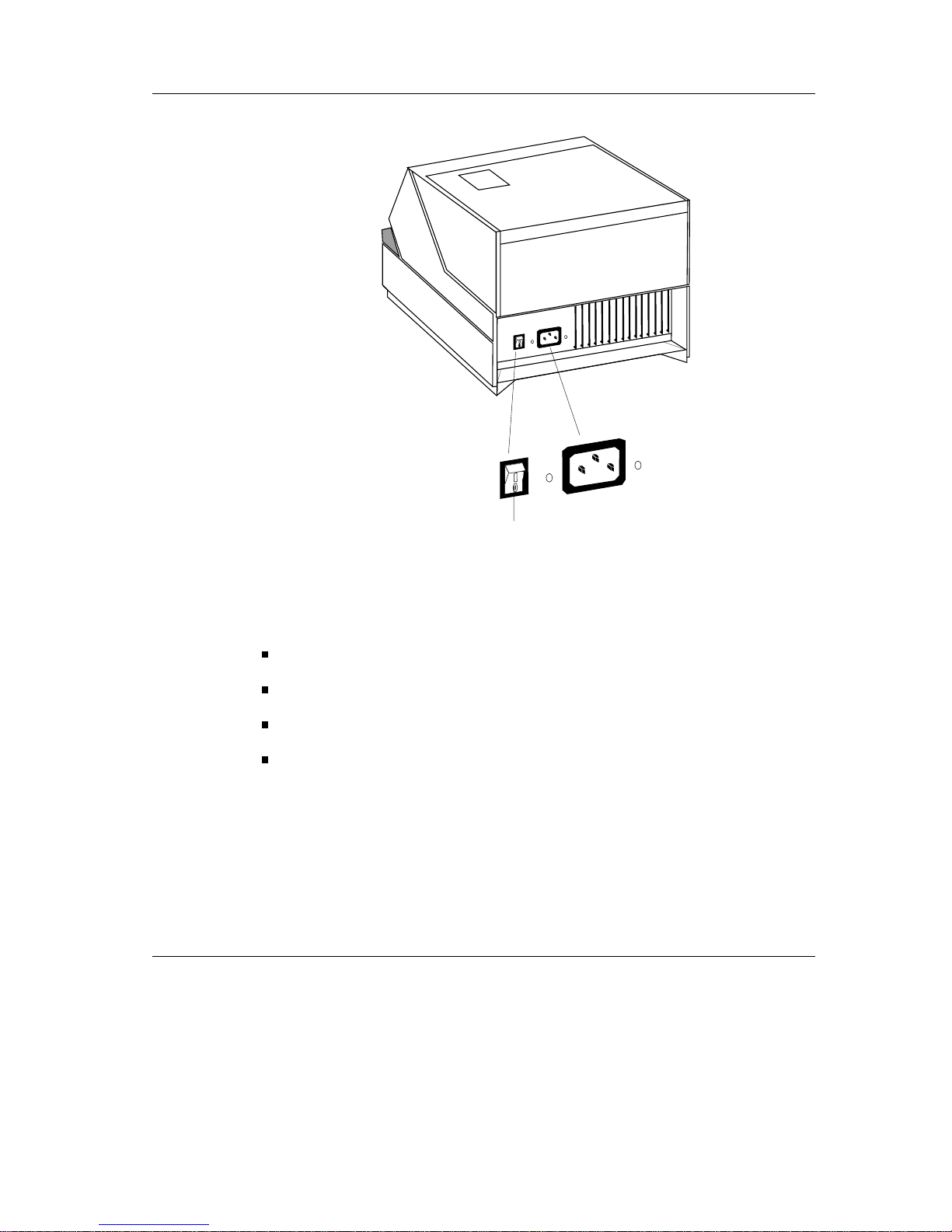
Cabling of the ND69
The devices should be installed in the following order:
Make sure that the power switch on the back of the housing is set at the “off”
position.
Plug the power cable into the power cord receptacle on the printer.
Plug the power cable into the mains socket.
Plug in and secure the data communication cable.
GB - 5

Securing the Data Communication Cable
Installation
The interface connectors can be secured
with the knurled screws manually.
The interface connectors with standard
screws can be secured with a screwdriver.
Connecting to the Mains Power Supply
MainsPower Supply
All devices belonging to the ND69 system that have a separate power cable must be
connected to the same electric circuit.
Ensure that the power switch on the POS terminal housing is switched off.
Make sure that all data cables on the system unit and all the peripherals are con-
nected correctly.
Plug all the power cables from the peripherals into the grounded-contact mains
supply sockets.
The settings require no additional alteration on the part of the user as the adapter on the
printer adapts automatically to the local mains voltage.
You can now switch on the ND69 by means of the switch on the back of the housing.
Mains Power Supply Installation
GB - 6
Disconnecting Cables
POSSystem
Never unplug a cable by pulling at the cable itself; always take hold of the actual plug
body. Follow the procedure described below when disconnecting cables:
Switch off all power and device switches.
Unplug all data communication cables from the sockets of the data networks.
Unplug all power plugs from the grounded-contact mains power sockets.
Unplug all cables from the devices.
On/Off switch
Installation POS System
GB - 7
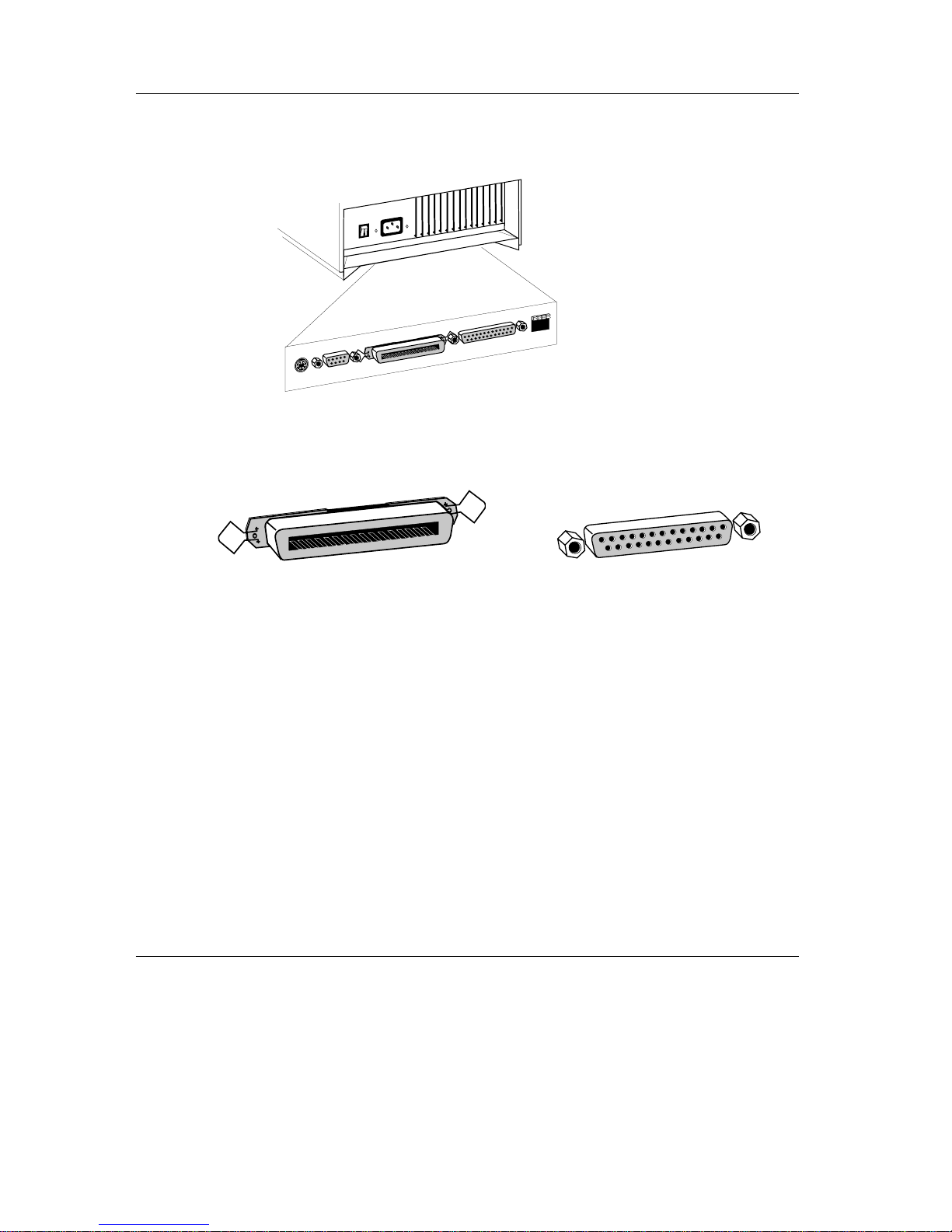
Connecting to the POS System
The ND69 can be connected either to the Centronics socket (parallel interface) or to the
V.24 interface (serial interface) on the POS system. The printer automatically recognizes
which possibility for connection you have selected.
DIP Switches
DIPSwitches
TheDIPswitchesmakeitpossiblefortheND69tobeoperatedintheND69modeorto
be compatible with other printers so that existing application software can be used.
The DIP switches are located on the terminal strip on the underside of the ND69, on the
right, beside the V.24 interface.
Centronics socket
V.24 interface
1
2
3
4
The terminalstrip is located
on the underside of the
ND69
DIP Switches Installation
GB - 8

Default setting
DIP Switch 1: Meaning of the parallel interface SELECT signal.
Switch on SELECT represents the COVER SWITCH, i.e.
SELECT = “HIGH” -> cover closed
SELECT = “LOW” -> cover open
Switch off SELECT indicates whether the parallel or the V.24 interface
is active
SELECT = “HIGH” -> parallel interface is active
SELECT = “LOW” -> serial interface is active
DIP Switch 2 and These two switches serve to select the compatibility and set the
DIP Switch 3 effects of control commands between the operating modes
ND69 mode
BEETLE/60 mode or
EPSON-TM930 mode
Moreover, the switches are used to execute an AUTOFEED,
i.e. an automatic line feed with the control character CR.
Switch 2 off and The ND69 is in the ND69 mode and CR is executed without a
Switch 3 off line feed
Switch 2 on and The ND69 is in the BEETLE/60 mode and CR is executed
Switch 3 off without a line feed
Switch 2 off and The ND69 is in the EPSON-TM930 mode and CR is
Switch 3 on executed without a line feed
Switch 2 on and 1. The ND69 is in the EPSON-TM930 mode and the parallel
Switch 3 on interface is active.
ON
OFF
2
3
4
1
Installation DIP Switches
GB - 9
The parallel interface signal AUTOFEED/N
determines whether CR executes an automatic
line feed.
AUTOFEED/N = “HIGH” - CR without line feed
AUTOFEED/N = “LOW” - CR with line feed
2. TheND69 is in the EPSON-TM930 mode and the V.24
interface is active:
CR is executed with a line feed.
DIP Switch 4: Selection of DTR/DSR or XON/XOFF control
Switch on XON/XOFF control is switched on
Switch off DTR/DSR control is switched on
Default setting:
DIP 1 ON
DIP 2 OFF
DIP 3 OFF
DIP 4 OFF
Compatibility
Compatibility
The combined controller is executed in such a way that the ND69 - depending on the
position of two DIP switches (see Chapter DIP Switches) - either works in the ND69
mode, is compatible with the BEETLE/60 printer or with the EPSON-TM930 printer and
thus understands the control characters and sequences that apply in each case. More
details on the individual commands in various modes is provided in the chapter on
control sequences. Please note that the Centronics-Interface is not supported by the
BEETLE /60 mode.
Compatibility Installation
GB - 10

Data Retention and Loss When Opening Cover
In BEETLE/60 mode, opening the cover during printing leads to a device fault. The printer
is then blocked and remains so until it is re-initialized. Prior to the new initialization, all
data which are in the reception buffer or are received by the printer are lost.
When the cover is opened during printing in ND69 mode and in EPSON-TM930 mode,
the current printing is interrupted at the end of a line. Subsequent data and commands
remain stored in the reception buffer. As soon as the printer is closed and is ‘on-line’
again, the printing that was interrupted restarts.
Data Retention and Loss at Paper End
In BEETLE/60 mode, when the print stop sensors have been set, a check is carried out
as to whether paper is present at the selected station prior to every line feed and/or
printing operation. If there is no paper there, a user error is issued. All further data and
commands are ignored until the error message is queried (see control sequence
ESC + 1 and ESC v).
In ND69 mode and in EPSON-TM930 mode, paper end is reported when there is no
paper present at the selected station. All subsequent data and commands remain stored
in the reception buffer. As soon as paper is present and the printer is ‘on-line’ again, the
printer runs from the point where the printing operation was interrupted. No data are lost.
Connecting Peripherals
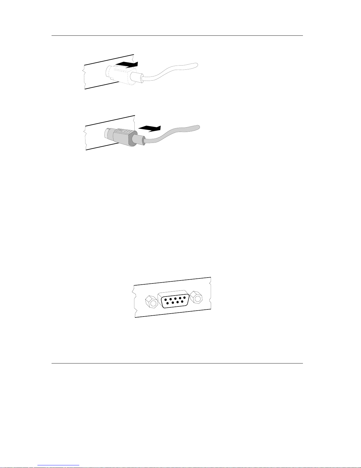
Cash Drawer (CASHDRW)
Peripherals
TheND69hasa6-pinmini-DINjackforconnectingacashdrawer.Toprevent
malfunctions, make sure that the connector is plugged firmly into the socket. Power is
supplied to the cash drawer via this socket.
Installation Peripherals
GB - 11
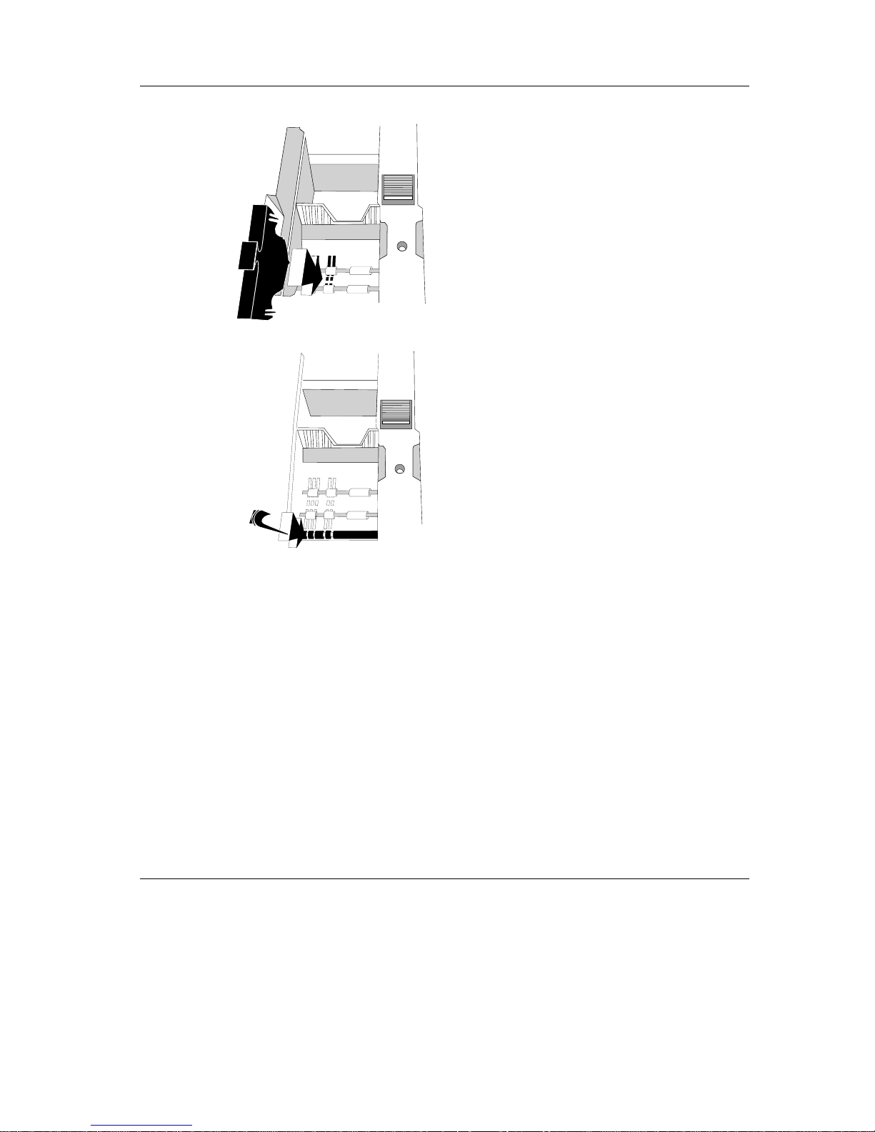
The cable remains connected until it is
released.
Use your thumb to remove the plastic
cover from the connection socket. The
locking mechanism is released.
The metal part of the connector is
visible. Now remove the cable from the
connectionsocket.
Customer Display
The customer display is connected to the serial interface. The interface connection on the
ND69 is a 9-pin D-sub connector.
To prevent possible malfunctions, make sure that the connector for the customer display
is plugged firmly into the socket. The power is supplied via this jack.
Peripherals Installation
GB - 12
The Operator Control Panel
TheOperator Control Panel
The online button and the button for receipt and journal line feed are part of the operator
control panel. All keys are locked or released by means of the command ESC c 5.
The foil on the online button can be replaced by one with country-specific lettering.
Online Button
This button switches between the “online” and “offline” modes. In normal operation the
printer is “online” anditisabletoprintdata.Whenitisswitchedto“offline”,theprinter
stops at the end of the current line. Possbile offline modes: error, paper end, and cover
open. The online button can be disabled with the command ESC c 6. When it is disabled,
the printer is in the “online” mode. This mode cannot then be changed by means of the
online button. After switching on the ND69 in the BEETLE /60 mode, the online key is
locked because the BEETLE /60 printer itself does not have an online key.
Receipt Line Feed Button
Alinefeedatthereceiptstationisexecutedwhenthisbuttonispressed.Thelinespacing
corresponds to either the default value of 1/6", or it depends on t he last command it
received, ESC 2 or ESC 3. The printer executes uninterrupted line feeds for as long as
the button remains pressed.
When the online button is released, the receipt line feed button can only be pressed if the
printer is in the “offline” mode. If the online button has been disabled, the receipt line feed
button is always active.
If the cover is closed, the line feeds are effected slowly (approx. 7 lines/sec). If the cover
is open, the line feeds are effected quickly.
Installation The Operator Control Panel
GB - 13

Journal Line Feed Button
A line feed at the journal station is executed when this button is pressed. The line spacing
corresponds to either the default value of 1/6", or it depends on the last command it
received, ESC 2 or ESC 3. After pressing the foil button continuously for approx. 2
seconds, the printer carries out a continuous line feed for as long as the foil button
remains pressed.
When the online button is released, the journal line feed button can only be pressed if the
printer is in the “offline” mode. If the online button has been disabled, the receipt line feed
button is always active.
If the cover is closed, the line feeds are effected slowly (approx. 7 lines/sec). If the cover
is open, the line feeds are effected quickly.
LEDs
Green LED “on” This LED is connected to the mains supply and it lights up when
the printer is switched on.
Green LED “online” This LED lights up when the printer is in the “online” mode and
is off in the “offline” mode.
Red LED “error” This LED lights up when the cover is open. It flashes when a
device error has occured. During normal operation, it is off.
Red LED “paper end” This LED lights up, when either the receipt or the journal station
has recognized “paper end” and the corresponding paper sensor
is selected (see ESC c4n, page GB-60).
Yellow LED “document” This LED flashes while the printer is waiting for a document to
be inserted; it lights up continuously while the document is in the
printer; and it goes out when the document leaves the printer.
This LED is off when the document station has not been
activated.
The Operator Control Panel Installation
GB - 14
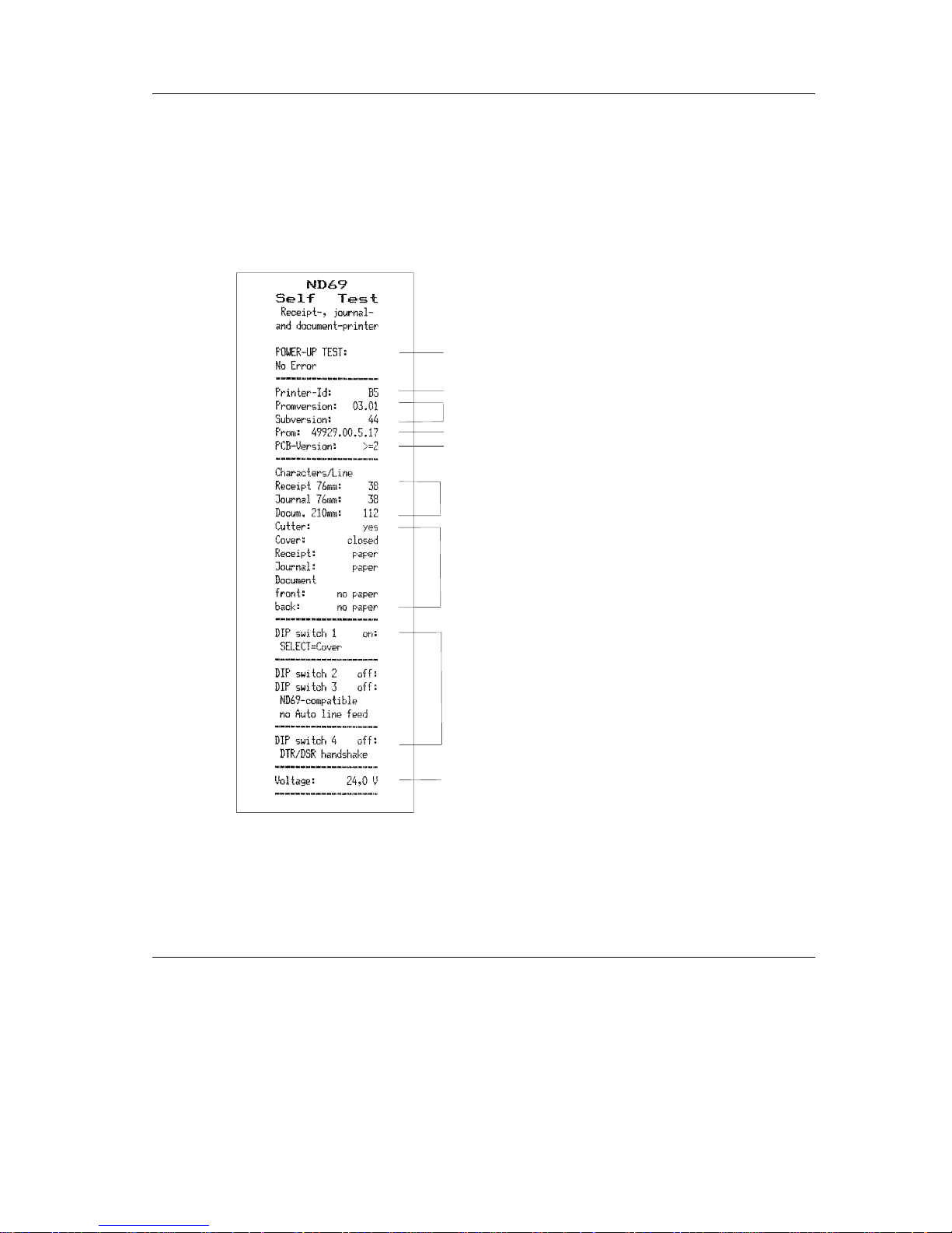
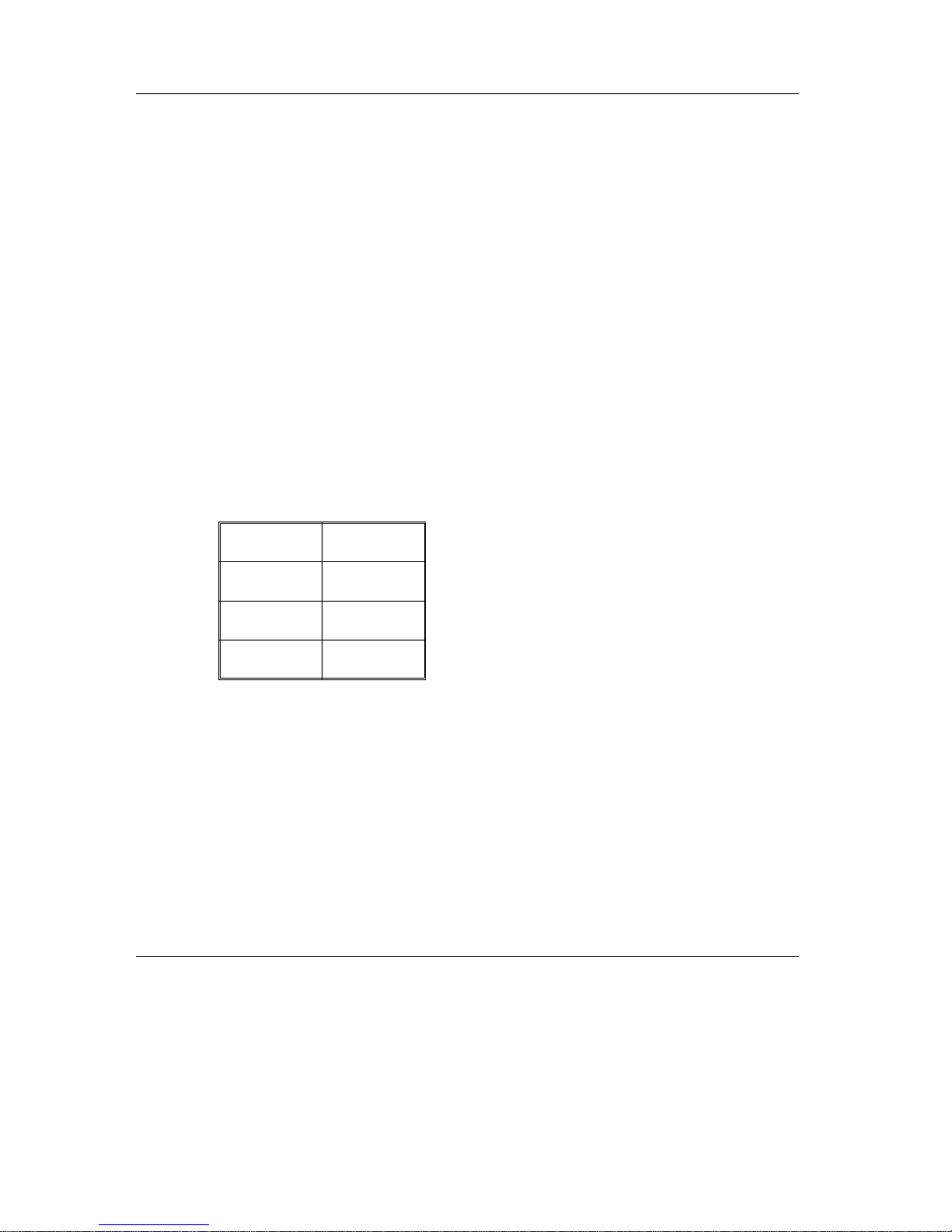
Self Test
SelfTest
The printer executes a self test if either the receipt or journal line feed button is pressed
while the device is being switched on. Depending on the pressed button the following
printout is produced either at the journal station or the receipt station.
A 24V measurement is carried out, and the result is printed
(max. deviation: ± 10%).
Default paper width setting
The device configuration is printed.
The status of all the sensors and the cover switch are checked
and printed.
Firmware version, in this example: Promversion 03,
Plug-in place 01 and sub-version 44
The power-up diagnosis is started. The result of the hardware
check is clearly printed at the receipt and/or journal station.
DIP switches (see also page 8 onwards)
Default:
1ON
2OFF
3OFF
4OFF
PCB-Version (Printed Circuit Board Version), i.e. 1 stands for
PCB-Version 1, >=2 stands for PCB-Version 2 or higher
Circulation number
Installation Self Test
GB - 15
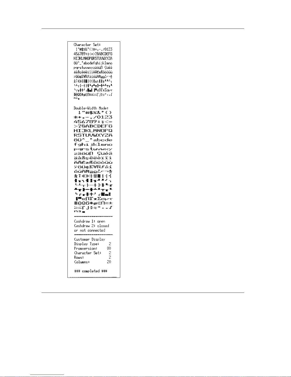
SelfTest
Installation
Character set
Complete character set, normal width
Complete character set, double width
The configuration and parameters for the customer display are
printed. The following appears on the customer display:
** ND69 SELF TEST **
*******************************
Following this, a document is requested (see example on
following page).
Cash drawer 1 is open.
Cash drawer 2 is closed or not installed.
At the end of the self test, the printer switches into the normal mode
and the customer display is extinguished.
Self Test Installation
GB - 16
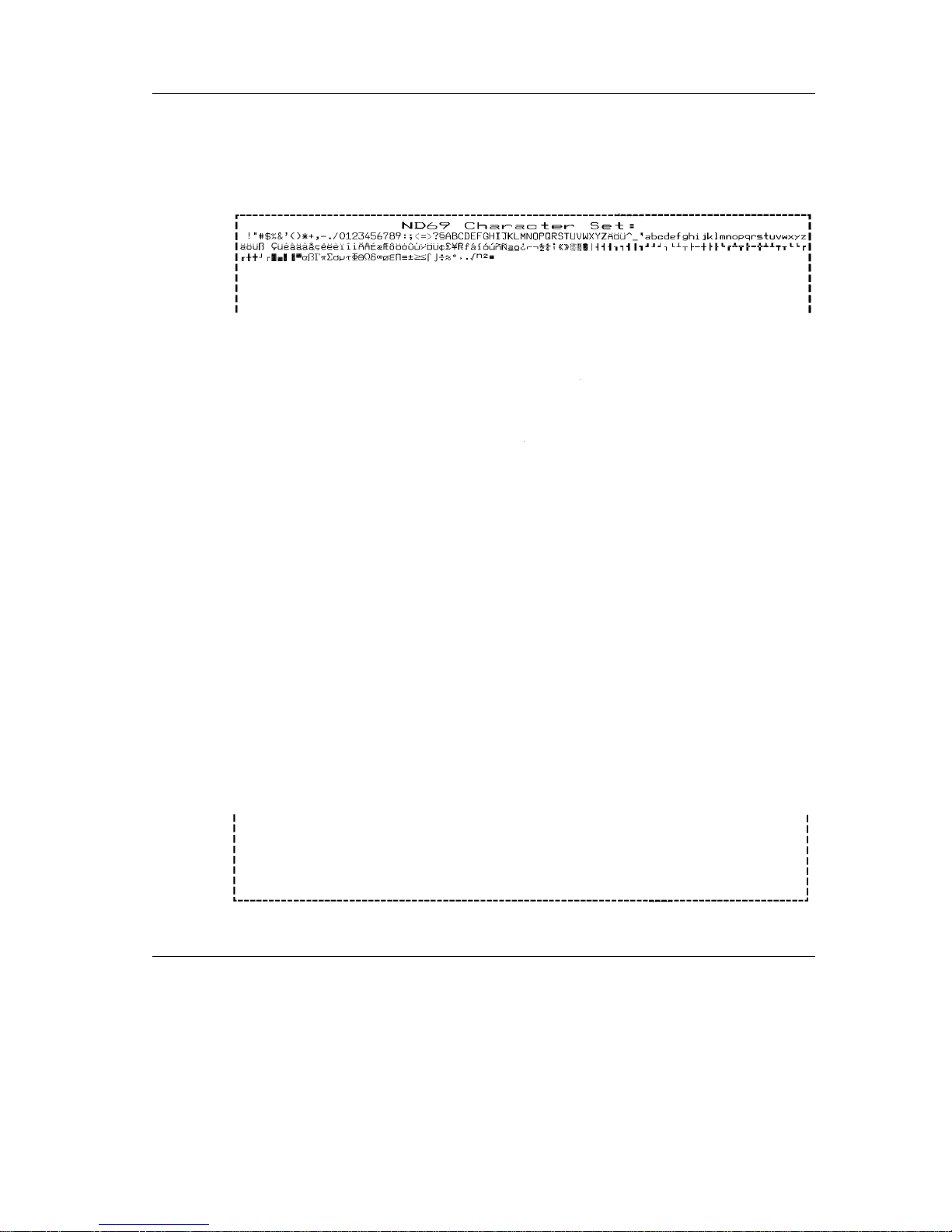
After the print-out of the self test on receipt or journal paper, the following A4 print-out is
produced; this print-out can take place on either an A4 sheet or is printed in lettersizeformat.
Installation Self Test
GB - 17

Hexadecimal Dump Function
The printer has the Hex-Dump function. This prints the data received from the host on the
receipt in hexadecimal form in the corresponding ASCII characters. This function has the
following features:
Hex-Dump is activated by switching on the printer and, at t he same time, holding
down the on-line key. As soon as the ND69 is in the Hex-Dump mode, it prints
out a heading on the receipt.
Characters below 20 Hex are represented in the ASCII field as decimal points.
While Hex-Dump is active, all commands - with the exception of GS ENQ - are
ignored.
The command RESET (ESC @) is also disabled.
The international set of characters used is the US character set.
The receipt roll used must have a minimum width of 76 mm.
Switch off the printer to exit from Hex-Dump.
HexadecimalDump Function
Hexadecimal Dump Function Installation
GB - 18

Operation of the ND69 POS printer
The ND69 POS Printer has 9-dot matrix printing mechanism which serves the three
printing stations for receipts, journals and documents. The resolution of the characters is
in 9
*
9 dot matrix or 7*9 dot matrix, depending on the character types selected in your
application software.
The ND69 provides you with the possibility of controlling the line feed of the receipt and
journal paper via two buttons on the front cover of the printer. There is a green line feed
button inside the housing for changing the receipt and journal paper.
For reasons of safety, the printing and cutting devices are shut down as soon an the
printer cover is opened.
Inserting the receipt and journal paper is made easier by a semi-automatic paper feed.
An individual company logo can be created by means of a block print which is produced
with graphic print quality. The logo is produced in your application software and loaded
into the printer memory.
Further device features are the high print speed and the simple operation.
All consumables for the printer, such as receipt and journal paper or ribbon cassettes can
be ordered from WN services.
For the sake of the environment, always dispose of used materials properly (see chapter
on Recycling).
GB - 19
Operationof the ND69 POSprinterInser tingthe Spacers
The ribbon in your printer has not been inserted in the document plate prior to delivery.
For further information, read the chapter on “Changing the Ribbon Cassette”.
As the ND69 allows different paper widths for receipt and journal paper, it might be
necessary to reduce the size of the paper reception compartments so that they can
accommodate narrower rolls of paper. This is done by means of the enclosed spacers,
and is described in the following chapter “Inserting the Spacers”.
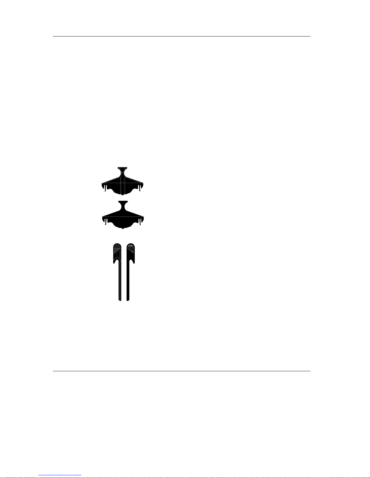
Inserting the Spacers
There are two spacers and two adapters
for the division of the receipt or journal
compartments in the additional package.
The larger spacers are suitable for both
compartments.
The long adapters are different for receipt
and journal (mirror images)!
When fitting these parts, ensure that the flat surfaces face the separating wall between
the receipt and journal compartments.
Inserting the Spacers Operation of the ND69 POS printer
GB - 20
Both paper compartments have five possible positions for the spacers/adapters.
Depending on the paper width, insert the
spacers into the appropriate grooves in the
paper compartment.
Then, as can be seen in the illustration, the
appropriate adapter is inserted in t he paper
feed magazine.
DocumentProcessing
Document Processing
The ND69 prints documents up to a size of DIN A4. Consult the appendix for the print
area and the paper specifications.
Operation of the ND69 POS printer Document Processing
GB - 21
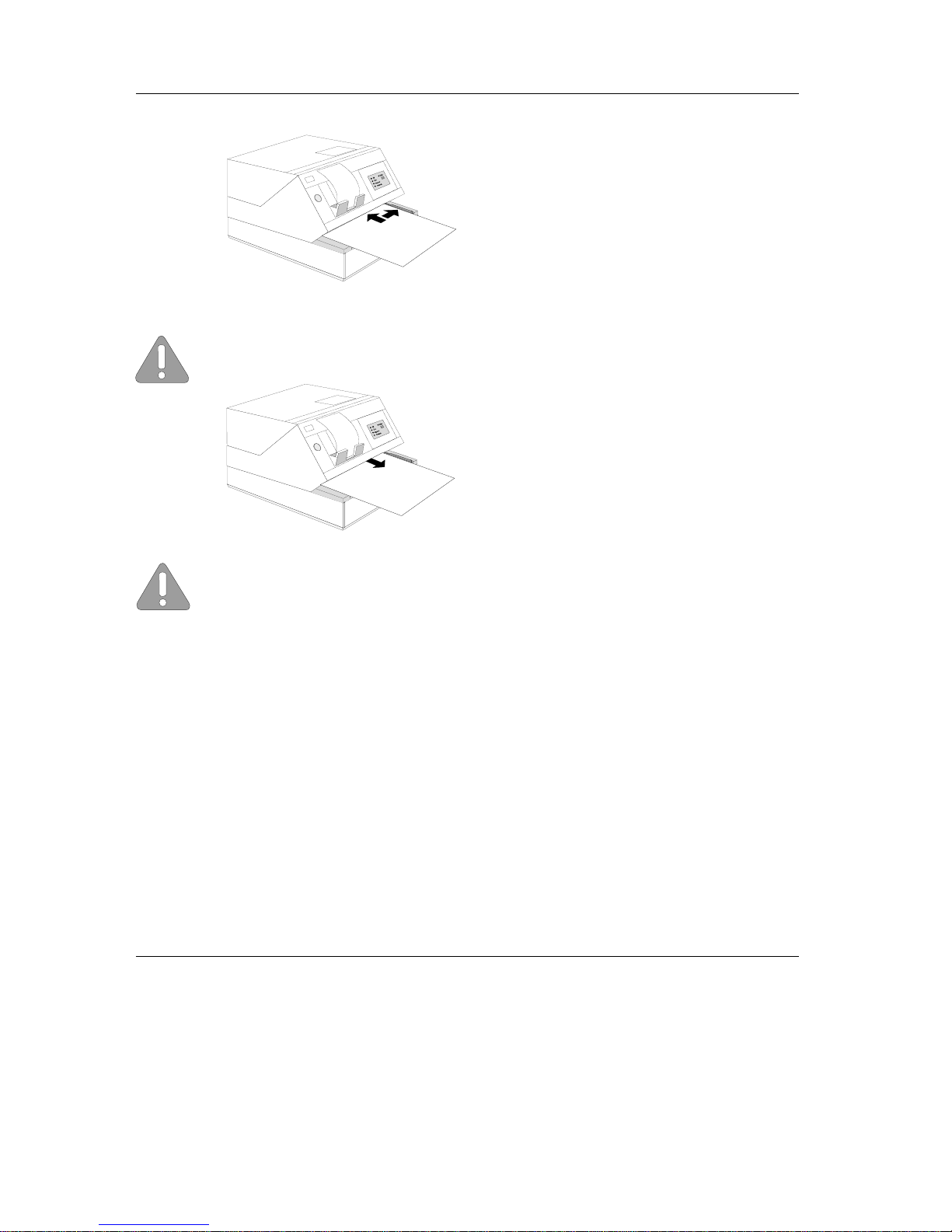
When the yellow LED flashes, place the
document to the right of the guide edge of
the document plate.
This applies particularly to documents
which are narrower than DIN A4 so that
the document sensors can recognize the
paper and draw it in correctly.
Then push the document towards the document infeed until the paper is gripped by
the transport rollers (start of transport motors).
Alwaysinsertthepaperinsuchawaythatthesidetobeprintedonisfacingdownwards.
After processing, the document is transported out of the printer and it can be removed.
If the document sensors recognize a document end during document processing,
although print data are still located in the print controller, this will lead to a printing stop. In
ND69 and EPSON-TM930 modes, take out the document and insert a second document
sheet if the yellow LED flashes. The printing can now be continued or completed, as the
case may be. In the BEETLE /60 mode, the application program regulates the paper
outfeed and the request for a new document (yellow LED flashes).
Changing the Receipt and Journal Paper
Changingthe Receipt and JournalPaper
The following are detailed descriptions of the individual steps for changing the paper. A
simplified version of the steps involved, in the form of pictograms, is on the underside of
the printer cover.
If neither receipt nor journal paper are in place - particularly important for first operation the receipt paper must be fitted into the paper feed first. Only then can the journal paper
be fitted.
Changing the Receipt and Journal Paper Operation of the ND69 POS printer
GB - 22

Green Paper Feed Button
When the cover of the printer is open, the green paper feed button for the receipt and
journal stations can be used. This button makes the inserting of a new roll of paper much
easier in that it changes the location of the feed rolls mechanically - in addition to the
electrically induced line feeds.
If you press the switch after the cover has been opened, paper will only be fed at the
station where the paper end sensor issues the message “paper present”. If there is paper
at both stations, it will be fed at both stations simultaneously.
If there is no paper present at one printing station, the feed motor at this station switches
on after the cover has been opened; it thus removes paper that might be left over.
If paper is inserted at a printing station after the cover has been opened, the feed motor
of this station switches on at a lower speed.
If the paper end sensor of a printing station issues the messsage “paper present” after the
paper is inserted, pressing the paper line feed button will produce a line feed at this
station only.
If paper is inserted at the receipt station, the paper is automatically fed further forward,
and thus tensioned, when the cover is closed; it is subsequently cut in order to have an
evenly cut edge.
The paper line feed button is only active when the cover switch issues the message
“cover open”.
Changing the Receipt Roll
If a red stripe appears on the printed receipt, or the “paper end” LED lights up on the
control panel, a new receipt roll should be inserted. Change the receipt roll as follows:
Operation of the ND69 POS printer Changing the Receipt and Journal Paper
GB - 23
Remove the remaining receipt paper
Lift up the paper compartment cover to
gain access to the paper roll. You can remove the remaining paper by means of the
line feed button.
Then, take out the empty paper roll. Continue with “Inserting the Receipt Roll”.
If there is still unused receipt paper on the receipt roll, remove it as follows:
Take the receipt roll out of the compartment and cut the receipt roll so that an evenly cut
edge is created. Now you can remove the remaining paper with the help of the paper line
feed button.
Do not tear the remaining receipt paper in such a way that you leave it too short! If it is
not possible to remove the paper by means of the paper line feed, it is quite easy to
remove manually.
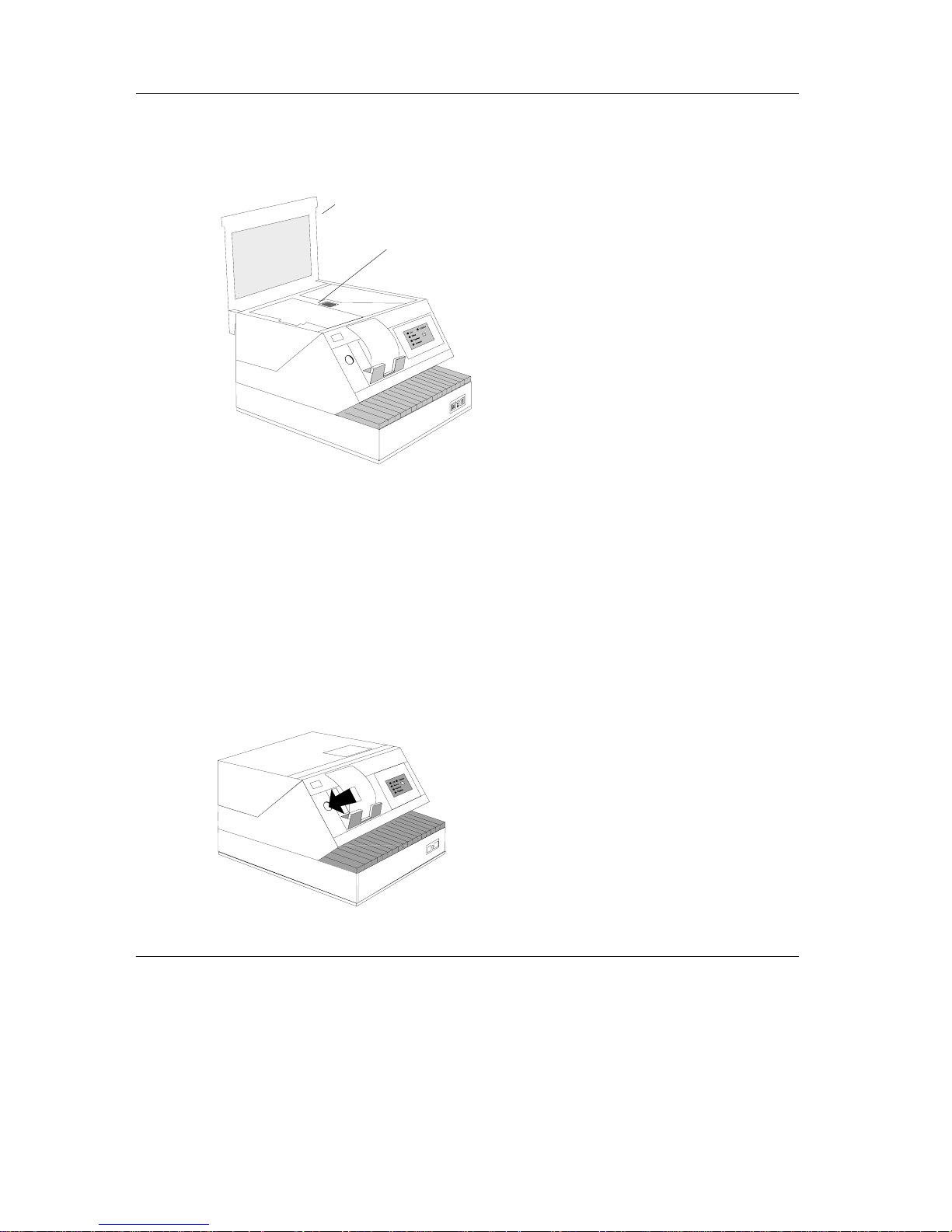
If it is not possible to take out the receipt paper by means of the paper line feed, it can be
taken out as follows:
Open the upper part of the printer by lifting
it backwards while pressing the release button.
Paper line feed button
Pictograms for handling
Changing the Receipt and Journal Paper Operation of the ND69 POS printer
GB - 24

Draw the green lever backwards to raise
the printing mechanism.
Now pull the receipt paper straight upwards and out of the paper magazine.
Do not pull the remaining paper out of the paper magazine while it is still fitted in the
paper guide! The printing mechanism must be in the raised position.
Set the lever forwards to lower the printing mechanism. Close the upper part of the
printer; you should hear it click into place.
Inserting the Receipt Roll
Open the cover of the paper compartment.
Make sure that the paper on the new receipt roll is evenly cut. Insert the new receipt roll in the paper compartment as
shown in the illustration.
Only use paper which is intended to be used for your purpose, and which is acceptable
for your printer. The spacers and adapters might have t o be inserted (see “Inserting the
Spacers”).
Operation of the ND69 POS printer Changing the Receipt and Journal Paper
GB - 25
 Loading...