

Wincor Nixdorf M1, M2 User Manual

M1 and M2 POS Motherboard
(with BIOS Setup)
User Manual (Edition May 2017)

We would like to know your opinion on this publication.
Your opinion:
Please send us a copy of this page if you have any constructive criticism.
We would like to thank you in advance for your comments.
With kind regards,
Wincor Nixdorf International GmbH
Documentation R&D BLN 2
Wohlrabedamm 31
D-13629 Berlin
E-Mail: retail.documentation@wincor-nixdorf.com
Order No.: 01750297725A

M1 and M2 POS Motherboard
User Manual
Edition May 2017

All brand and product names mentioned in this document are trademarks of
lability; technical
their respective owners.
The re production, transmission or use of this document or its contents is not permitted without
express authority. Offenders will be liable for damages. All rights, including rights created by patent
grant or registration of a utility model or design, are reserved. Delivery subject to avai
Copyright © Wincor Nixdorf International GmbH, 2017
modifications possible.

Overview ....................................................................................... 7
Introduction ....................................................................................... 7
Some Highlights of the M1 and M2 Motherboard ............................ 7
Motherboard Specification ............................................................ 9
Mainboard assembly variants ............................................................ 9
Block Diagram .................................................................................. 10
CPU support ..................................................................................... 11
Mainboard internal connectors and onboard features ................... 12
Memory (internal) ....................................................................... 12
Serial ports (internal)................................................................... 13
LPT (internal) ............................................................................... 14
USB 2.0 (internal) ........................................................................ 14
Mini PCI Express /mSATA (internal) ............................................ 15
M.2 (internal) .............................................................................. 16
SATA (internal) ............................................................................ 17
TPM (internal) ............................................................................. 17
PCI Express Slots (internal) .......................................................... 18
Front panel connector (internal) ................................................. 18
Chassis intrusion connector (internal)......................................... 20
Clear CMOS jumper (internal) ..................................................... 21
Config Connector (internal) ......................................................... 21
Fan (internal) ............................................................................... 21
ATX / 12V Power connector (internal) ........................................ 22
Voltage regulator......................................................................... 23
XHCI USB controller ..................................................................... 23
Processor Graphics ...................................................................... 23
Audio ........................................................................................... 24
Supported Sleep States ............................................................... 24
S0 ................................................................................................. 24
Normal Operation (“ON”)............................................................ 24
S3 ................................................................................................. 24
Suspend to RAM / “Stand By” ..................................................... 24
S4 ................................................................................................. 24
Suspend to Disk / “Hibernation” ................................................. 24
S5 ................................................................................................. 24
Soft Off ........................................................................................ 24
System wake up........................................................................... 25
DeepSleep ................................................................................... 25
M1 and M2 Motherboard, User Manual 1

BIOS Flash devices ....................................................................... 25
Mainboard onboard connectors with external access ..................... 26
Motherboard I/O shield overview (external) .............................. 26
PanelLink 2.0 (external) ............................................................... 26
VGA (external) ............................................................................. 28
PS/2 Keyboard / Mouse (external) .............................................. 28
LAN (external) .............................................................................. 28
USB 2.0 / USB 3.0 (external) ........................................................ 28
Audio (external) ........................................................................... 28
Power supply requirements ............................................................. 29
Power load ability ............................................................................. 30
SMBus address table ........................................................................ 30
Frequency and bandwidth overview ................................................ 31
RAID (M1 Motherboard) .................................................................. 32
Technical Data .............................................................................. 33
Changing the Battery .................................................................... 35
UEFI BIOS Setup ........................................................................... 36
Standard UEFI BIOS Version ............................................................. 36
BIOS Menu Bar ................................................................................. 37
Legend Screen .................................................................................. 38
General Help .................................................................................... 38
Scroll Bar .......................................................................................... 38
Sub-Menu ........................................................................................ 39
Info Screen ....................................................................................... 39
BIOS Revision: .............................................................................. 40
LAN1 MAC Address: ..................................................................... 40
UUID Info: .................................................................................... 40
Product Name: ............................................................................. 40
System, Mainboard, Power Supply: ............................................. 40
Main Menu .................................................................................. 41
System Information .......................................................................... 41
Open source software license information ...................................... 41
System Language.............................................................................. 41
System date ...................................................................................... 42
System time...................................................................................... 42
2 M1 and M2 Motherboard, User Manual

Advanced Menu ........................................................................... 43
Onboard Devices Configuration ....................................................... 44
Display Output to COM [Disabled] .............................................. 44
LAN Controller [Enabled] ............................................................. 44
Azalia HD Audio [Enabled] ........................................................... 44
CPU Configuration............................................................................ 45
Active Processor Cores ................................................................ 45
Intel Virtualization Technology [Enabled] ................................... 45
VT-d [Enabled] ............................................................................. 46
SW Guard Extensions (SGX) [Software Controlled] ..................... 46
Enhanced SpeedStep [Enabled] .................................................. 46
Turbo Mode [Disabled] ............................................................... 46
Aperture Size [256 MB] ............................................................... 46
CPU AES [Enabled] ....................................................................... 46
Drive Configuration .......................................................................... 47
SATA Mode .................................................................................. 47
Aggressive Link Power Management [Enabled] .......................... 47
SMART Settings ................................................................................ 48
Smart Self Test [Disabled] ........................................................... 48
CSM Configuration ........................................................................... 49
Launch PXE OpROM Policy [Legacy only] .................................... 49
Launch Storage OpROM Policy [Legacy only] .............................. 49
Launch Storage OpROM Policy [Legacy only] .............................. 49
Other PCI device ROM priority [Legacy only] .............................. 49
Trusted Computing .......................................................................... 50
TPM Support [Disabled] .............................................................. 50
TPM Device Selection [PTT] ......................................................... 50
USB Configuration ............................................................................ 51
USB Devices ................................................................................. 51
Legacy USB Support [Enabled] .................................................... 51
PS/2 Emulation [Enabled] ............................................................ 52
USB Mass Storage Driver Support [Enabled] ............................... 52
XHCI Hand-off [Disabled] ............................................................. 52
Port 60/64 Emulation [Enabled] .................................................. 52
USB transfer time-out ................................................................. 52
Device reset time-out .................................................................. 52
Device power-up delay ................................................................ 52
USB Port Security......................................................................... 52
Hardware Monitor ........................................................................... 53
M1 and M2 Motherboard, User Manual 3

Super IO Configuration ..................................................................... 54
Serial Port Configuration ............................................................. 54
Parallel Port ................................................................................. 54
Serial Port Console Redirection ........................................................ 55
Console Redirection [Disabled] ................................................... 55
AMT Configuration ........................................................................... 56
ME Version .................................................................................. 56
Intel AMT [Enabled] ..................................................................... 56
USB Provisioning of AMT [Disabled] ............................................ 57
Unconfigure ME [Disabled] .......................................................... 57
BIOS Hot Key pressed [Disabled] ................................................. 57
ME Unconfigure on RTC Confirmation [Enabled] ........................ 57
ME FW Image Re-Flash [Disabled] ............................................... 57
Hide Unconfigure ME Confirmation Prompt [Disabled] .............. 57
MEBx Selection Screen [Disabled] ............................................... 57
PET Progress [Enabled] ................................................................ 57
ASF support [Enabled] ................................................................. 58
WatchDog [Disabled] ................................................................... 58
Network Stack Configuration ........................................................... 59
Network Stack [Enabled] ............................................................. 59
Ipv4 PXE Support [Enabled] ......................................................... 59
Ipv6 PXE Support [Enabled] ......................................................... 59
Graphics Configuration .................................................................... 60
Primary IGFX Display.................................................................... 60
Primary Display ............................................................................ 60
Internal Graphics ......................................................................... 60
DVMT Shared Memory Size ......................................................... 61
DVMT Total Graphics Memory Size ............................................. 61
ACPI Settings .................................................................................... 62
Enable ACPI Auto Configuration [Disabled] ................................. 62
Enable Hibernation [Enabled] ...................................................... 62
ACPI Sleep Sate [S3 (Suspend to RAM)] ....................................... 62
Lock Legacy Resources [Disabled] ............................................... 62
S3 Video Repost [Disabled] .......................................................... 62
OEM Settings .................................................................................... 63
RTC Lock [Enabled] ...................................................................... 63
BIOS Lock [Enabled] ..................................................................... 63
Prevent External NVRAM Module [Enabled] ............................... 63
Intel Ethernet Connection ................................................................ 64
4 M1 and M2 Motherboard, User Manual

NIC Configuration ........................................................................ 64
Security ........................................................................................ 65
Administrator Password .............................................................. 65
Intrusion Detection [Disabled] .................................................... 66
Administrator Password .............................................................. 66
System Firmware Update [Enabled] ............................................ 66
Secure Boot configuration ........................................................... 67
Secure Boot Control [Enabled] .................................................... 67
Secure Boot Mode [Standard] ..................................................... 67
Power .......................................................................................... 68
Restore AC Power Loss [Switch off] ............................................ 68
USB Power[Always off] ................................................................ 68
Wake-Up Resources .................................................................... 69
Power Control ............................................................................. 70
Event Logs .................................................................................... 71
Change SMBIOS event log settings .............................................. 71
Boot ............................................................................................. 73
Bootup NumLock State ................................................................ 73
Quiet Boot ................................................................................... 74
Configures the screen resolution ................................................ 74
Boot Order Menu ........................................................................ 74
Boot mode select [LEGACY] ......................................................... 74
Fixed Boot Order Priorities ‘#n’ Boot Device ............................. 74
Save & Exit ................................................................................... 75
Save Changes and Reset .................................................................. 75
Discard Changes and Reset .............................................................. 75
Save Changes and Power off ............................................................ 75
Restore Defaults .............................................................................. 76
Boot Override .................................................................................. 76
Test Points Codes ......................................................................... 77
Checkpoint Ranges ........................................................................... 77
Standard Checkpoints ...................................................................... 78
Phase SEC .................................................................................... 78
PEI Phase ..................................................................................... 79
PEI Beep Codes ............................................................................ 82
DXE Phase .................................................................................... 82
M1 and M2 Motherboard, User Manual 5

OEM-Reserved Checkpoint Ranges ............................................. 86
Abbreviations ............................................................................... 87
6 M1 and M2 Motherboard, User Manual

Overview
Introduction
This manual describes the features of two variants of a Motherboard based
on the Intel 100 series chipset Q170 and H110, formerly known as Skylake.
These M1 and M2 Motherboards were primarily designed for the Wincor
Nixdorf POS System BEETLE /M-III.
Some Highlights of the M1 and M2 Motherboard
th
6
and 7th Generation Intel® Core™ Processors, formerly known as
Skylake and Kaby Lake
Intel 100 series chipset Q170 and H110
CPU integrated graphic controller up to Intel® HD Graphics 630,
depending on used processor
AMT 11.6 support at M1 motherboards
2x WN Panellink 2 interfaces
1x VGA interface
Gigabit LAN onboard (Intel® Ethernet Connection; Q170: i219-LM,
H110: i219-V)
3 SATA III ports
2x DDR4 SODIMM sockets, supporting up to 32GB (2x16GB) at
2133/2400MHz. Only ~2GB available for 32bit OS
1x PCI Express x16 gen3
2x PCI Express x1 gen3
6 COM ports. COM1 is unpowered, COM2-6 have the option to be
powered
M1 and M2 Motherboard, User Manual 7

1 LPT port
MiniPCIe socket (full size) supporting the WN NVRAM module
M.2 (PCIe x4/SATA) on M1
1x PS2 (KBD/MS)
2 USB3.0 ports
up to 10 USB2.0 ports (H110: 6 ports)
TFT- displays without DDC are not supported.
8 M1 and M2 Motherboard, User Manual

Motherboard Specification
Mainboard assembly variants
As mentioned above there are two motherboard variants: The M1 board
with Q170 chipset supporting AMT, RAID, M.2 and mPCIe and the M2
board with H110 chipset as value edition supporting lesser features.
M1 and M2 Motherboard, User Manual 9
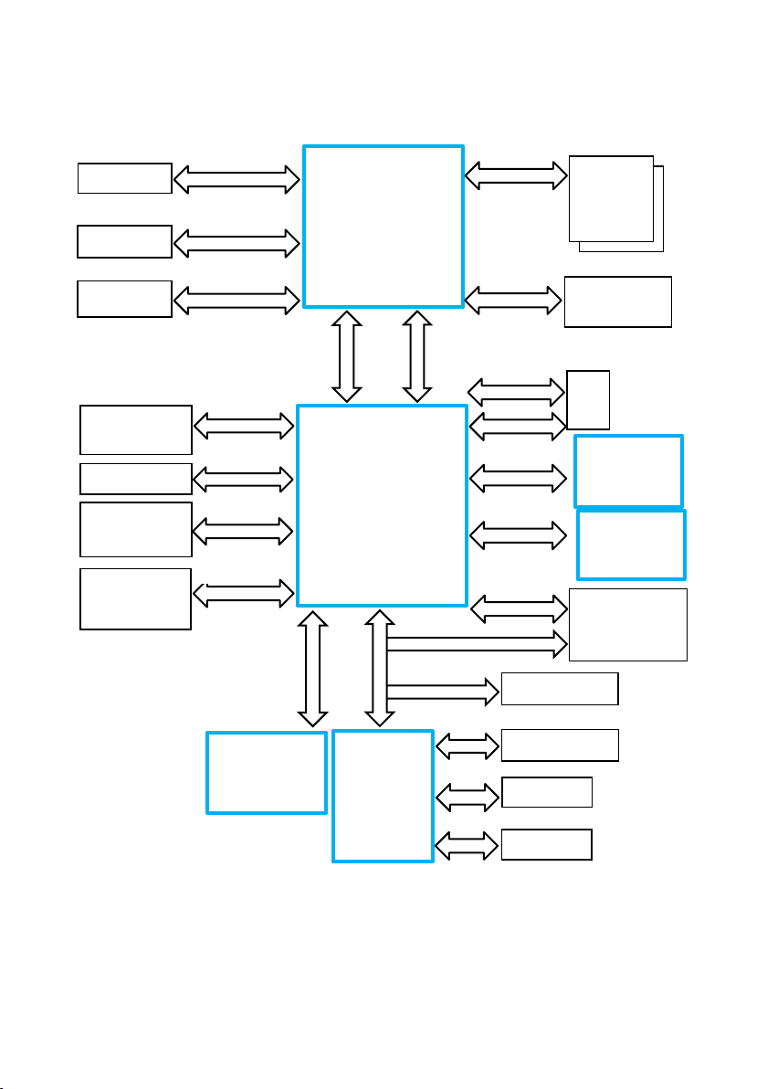
Block Diagram
SATA III
Panel Link 2
Panel Link 2
DMI
FDI
PCIe Gen3
SATA III
USB2.0
USB3.0
SPI
3x SATA Ports
HD Audio Link
COM
PCI Express x1
HD Audio
ALC671
LPT
PCI Express x1 /
SATAIII
Up to 6x COM
LPC
PCI Express x4
TPM Header
PS/2
PS/2
PCIe x16 Slot
2x PCIe x1 Slot
Up to 10 USB2.0
Ports
2x USB3.0 Ports
PCI Express 3.0
BIOS
64/128Mbit
LGA 1151
Skylake/Kaby Lake
CPU
65W TDP max.
Skylake PCH
Q170 / H110
LPC
LPC
SIO
NCT6106D
Dual Channel DDR4
DP (PTN3356)
LPT
2x DDR4
SODIMM
Socket
VGA
M.2
Codec
1Gb LAN
I219LM/I219V
mSATA/miniPCIe
10 M1 and M2 Motherboard, User Manual

CPU support
Base
Freqency
i5 (Kaby Lake)
i5-7500
4 4 3.4 (3.8)
HD
630
6MB
65
i5 (Skylake)
i5-6500
4 4 3.2 (3.6)
HD
530
6MB
65
i3 (Kaby Lake)
i3-7101E
2 4 3.9
HD
630
3MB
54
I3 (Skylake)
I3-6100
2 4 3.7
HD
530
3MB
51
Pentium
(Skylake)
G4400
2 2 3.3
HD
510
3MB
54
Celeron
(Skylake)
G3900
2 2 2.8
HD
510
2MB
51
CPU
CPU#
#CPU
core
#Threads
(Turbo)
GFX
Cache
size
TDP
[W]
M1 and M2 Motherboard, User Manual 11
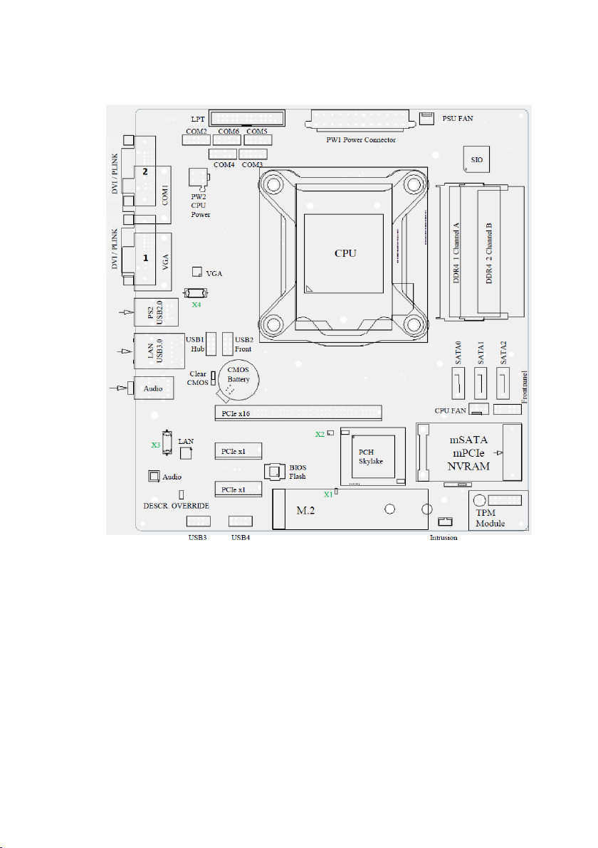
Mainboard internal connectors and onboard features
Memory (internal)
The mainboard provides two DDR4 unbuffered SODIMM sockets supporting up to 32GB in dual channel mode. The horizontal mounting of the
SODIMM sockets ensures an optimal air flow.
DDR4 I/O Voltage of 1.2 V.
4Gb and 8Gb DDR4 DRAM device technologies are supported.
The amount of installed memory that can be used may vary based on the
BIOS settings and the used OS.
Total Video memory size up to 1536MB of the installed memory.
(Pre-allocated Video memory size up to 1GB)
12 M1 and M2 Motherboard, User Manual
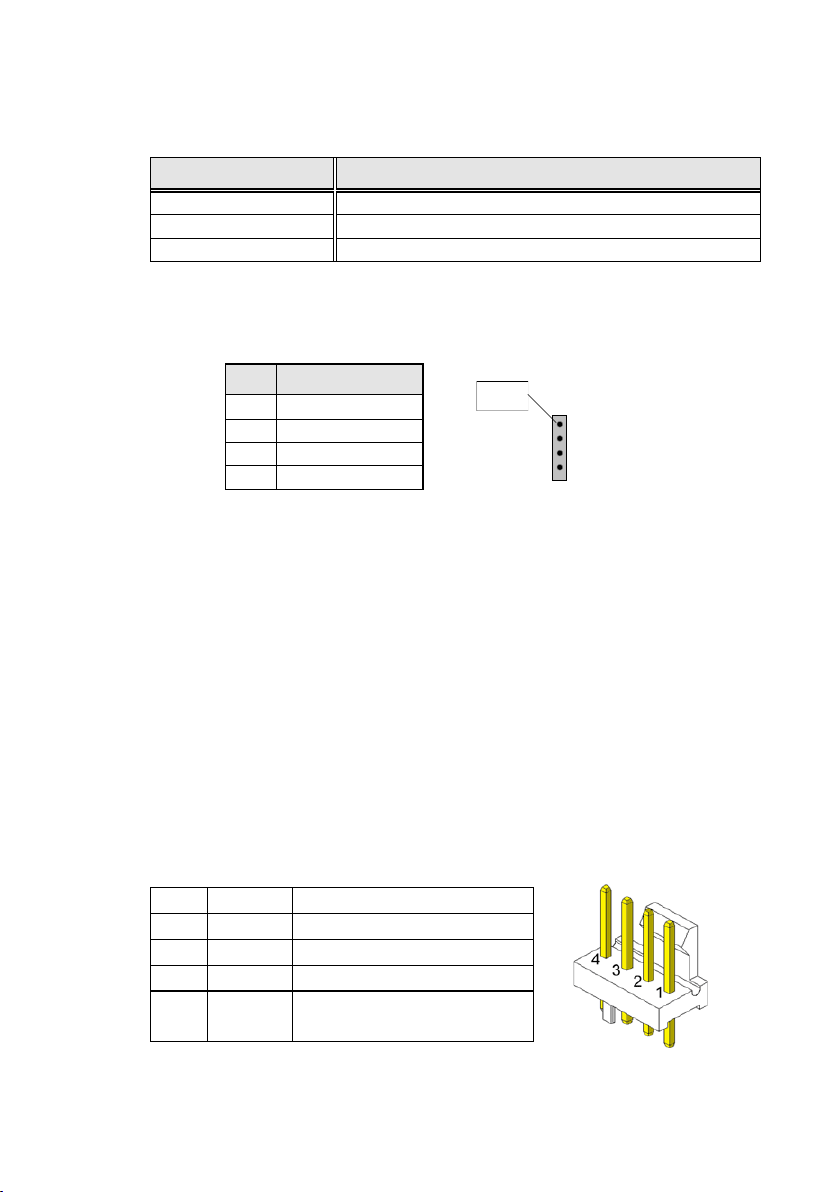
Serial ports (internal)
Pin
Signal
1
DCD 2 RX
3
TX
4
DTR 5 GND
6
DSR 7 RTS 8 CTS
9
RI
10
Key Pin
11
+5 V
12
+12 V
The mainboard provides 1 external and 5 internal COM ports (with FIFO,
16550 compatible) from NCT6106D.
COM2 -6 are configurable to standard or powered COM ports with an internal COM cable option (max current for powered COM: single port
300mA@5V; all ports together not more than 500mA@5V; single port
600mA@12V; all ports together not more than 900mA@12V).
Maximum voltage drop on 12V is 300mV, on 5V it is 150mV at full load.
This output is designed according to UL regulations and is protected by a
self-resettable fuse.
COM1 is a standard 9 pin DSUB connector in I/O shield.
2x 6 pin header, 2.54 mm pitch
M1 and M2 Motherboard, User Manual 13
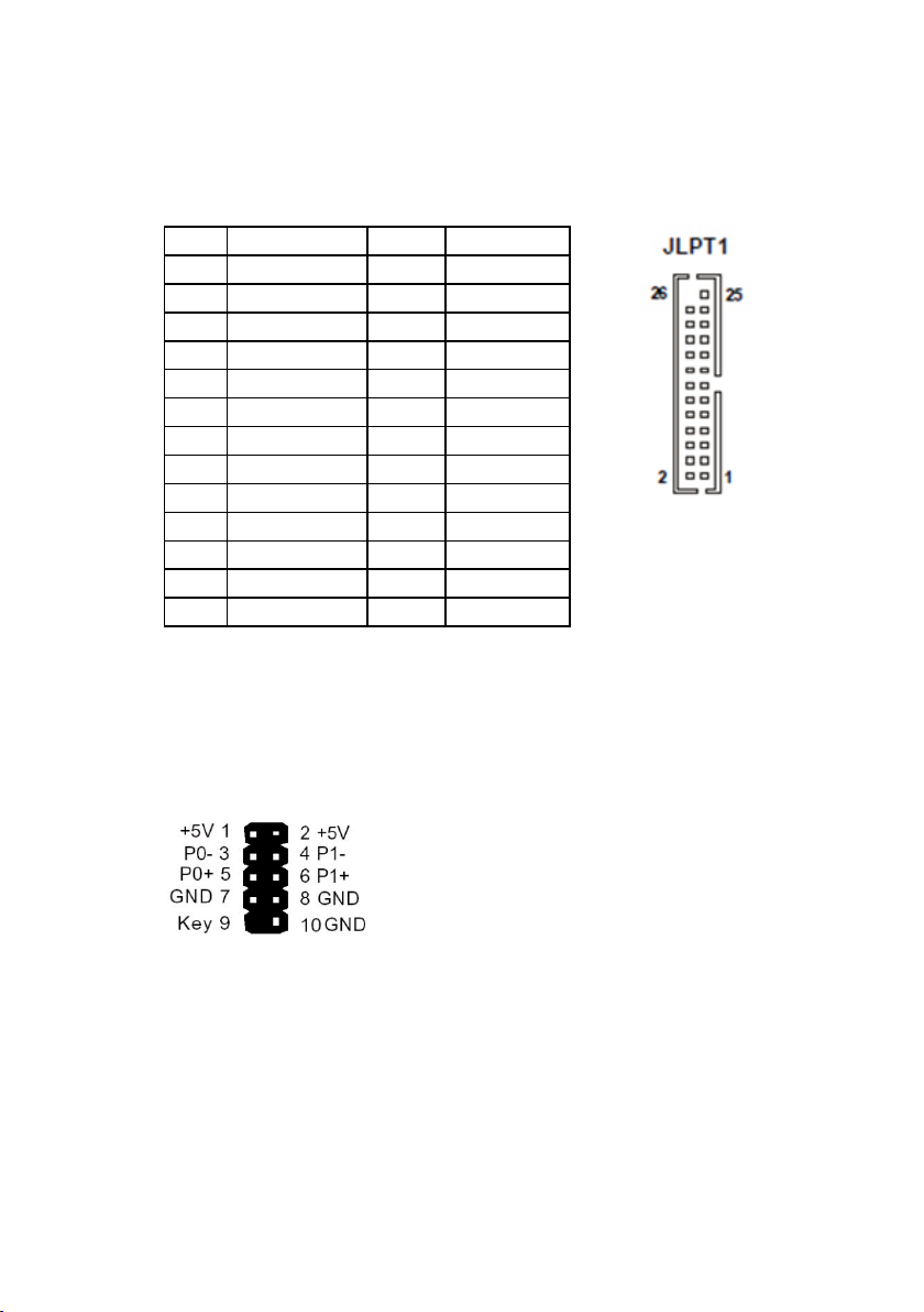
LPT (internal)
Pin
Function
Pin
Function
1
STR#
14
GND
2
AFD#
15
D6 3 D0
16
GND
4
ERR#
17
D7 5 D1
18
GND
6
PINIT#
19
ACK#
7
D2
20
GND
8
LPT_SLIN#
21
BUSY
9
D3
22
GND
10
GND
23
PE
11
D4
24
GND
12
GND
25
SLCT
13
D5
26
Key
LPT (IEEE1284 compliant) via NCT6106D.
Connector type: 26 pin shrouded header, 2.54mm pitch
USB 2.0 (internal)
7 USB ports at M1 board and 3 USB ports at M2 are routed to 10pin double
row headers with 2.54 mm pitch. These headers are intended to connect
optional front USB modules or USB hubs.
14 M1 and M2 Motherboard, User Manual
USB1_Hub port header contains only 1 USB port (pins 1,3,5,7)
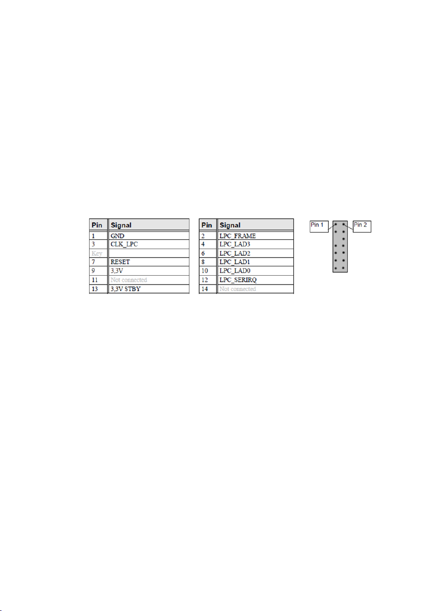
Mini PCI Express /mSATA (internal)
The mainboard provides a full size mini PCI Express / mSATA
connector. It is placed on top, thus being accessable without removing
other components. It supports LPC signals to support optional NVRAM
modules.
The power supply is only available in S0. There is no PCIe WAKE support.
The interface (SATA or PCIe) is automatically detected using Pin 51 of the
mSATA connector (GND = SATA; N.C = PCIe).
PCIe functionality is only supported on M1 motherboard.
Connector type: Standard MiniPCIe connector full size
M1 and M2 Motherboard, User Manual 15
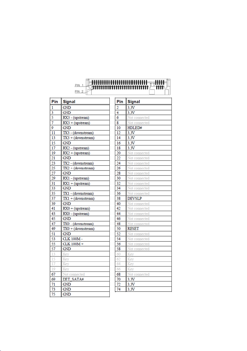
M.2 (internal)
The M.2 connector supports M.2 Key M modules with SATA or PCIe up to
x4 interface and a size of 2260 and 2280. The interface (SATA or PCIe) is
automatically detected using the PEDET Pin 69 of the M.2 connector (GND
= SATA; N.C = PCIe).
16 M1 and M2 Motherboard, User Manual
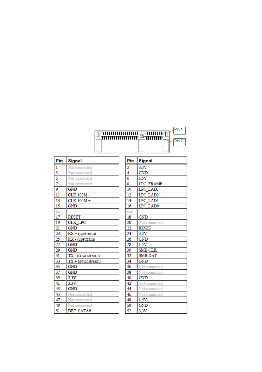
SATA (internal)
The mainboard provides three standard SATA ports. The ports SATA0
(white) and SATA1 (blue) and SATA2 (black) supporting SATA III connectivity speed. SATA3 port is connected to mSATA connector and SATA4 port is
connected to M.2 connector.
The RAID functionality is only supported by the M1 motherboard.
TPM (internal)
Trusted Platform Modules are a Trusted Computing Group (TCG) security
solution to increase the system security.
The Platform supports Intel PTT or TPM1.2 / TPM2.0 Modules connected
to the TPM connector.
M1 and M2 Motherboard, User Manual 17

PCI Express Slots (internal)
Indicator
Signaling
Description
ACPI State
Systemstate
‘Power
On’
System is full working
G0
S0
500ms on / 500ms off
‘Power On’ LED is off
G2
Deep Sleep
G3
‘Power On’ LED is blink-
There are two PCIe slots x1 Gen3 and one 1 PCIe slot x16 Gen3.
PCIe cards are able to wake up the system.
Thermal management: The input power of a single PCIe x1 card must not
exceed 10W and x16 card does not exceed 30W.
The PCIe slot at the outer side of the mainboard supports USB signals on
PCIe pins A5 (D-) and A8 (D+) as USB uplink connection and A6+A7 (VBUS)
to support specific Retail PCIe card.
Front panel connector (internal)
The mainboard supports a front panel connector to support service
elements (like POWER ON pushbutton, HDD and power LEDs).
18 M1 and M2 Motherboard, User Manual
‘Power On’ LED is
blinking equably
‘Power on’ LED is
off ‘Sleep’ LED
(orange) is on
‘Sleep’ LED (orange) is
off
ing
4x short then
repeated after
intermission
100ms on/ 900ms
System is sleeping. G1 S3
System is sleeping
and the contents is
saved on disk.
System is off.
Failure in Power Supply
G1 S4

‘Power On’ LED is blink-
ing 2x short then re-
Failure in CPU
ing
G1
S1 – S4
G2
S5
G3
peated after intermission:
100ms on/ 100ms off
100ms on/ 700ms off
…
Power Supply,
CPU or BIOS
Harddisk ‘Harddisk’ LED is flash-
Off No drive access
The BIOS is able to disable the power button during S0. Then it is not possible to shut down the system by the power button, even when pressed
longer than 4s. Power on from S5 is still possible.
Drive access G0 S0
M1 and M2 Motherboard, User Manual 19
The front panel header also supports speaker connection.
Pin Number
Function
1
Power switch +
2
Reset switch +
3
Power switch -
4
Reset switch -
5
Power LED +
6
Speaker -
7
Power LED -
8
Coding
9
HDD LED +
10
GND
11
HDD LED -
12
Speaker +
Pin Number
Function
1
GND
2
Intrusion input (switch to GND
if chassis is open)
3
n.c.
Type: 2x6 pin header, 2.54 mm pitch.
Chassis intrusion connector (internal)
The mainboard supports a chassis intrusion connector connected to the
PCH.
The intrusion monitoring is used to protect the system against unauthorized opening. This is detected, even if no AC is connected. However, this
will not be indicated until the system is operating again.
Type: 3 pin shrouded header, B3B-PH-K-S (JST) or equivalent.
20 M1 and M2 Motherboard, User Manual
Clear CMOS jumper (internal)
Pin
Signal
1
GND
2
RTC – Reset and load BIOS setup defaults
3
NC – Not Connected
Pin
Signal
Signal Description
1
GND
GND
2
12 V
Fan operation voltage
3
Sense
Tachometric signal
4
Control
PWM control signal (only
4 pin connector)
Pin
Signal
1
Password Skip
2
Password Skip
3
Recover BIOS
4
Recover BIOS
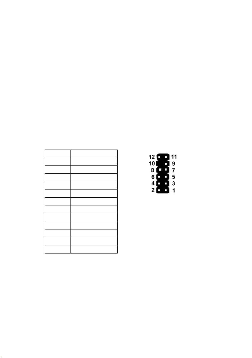
Config Connector (internal)
Jumper position 1-2: You can enter BIOS Setup without providing the
password, even if a password is set.
When doing so, the password is cleared.
Jumper position 3-4: You can load a special recovery BIOS image.
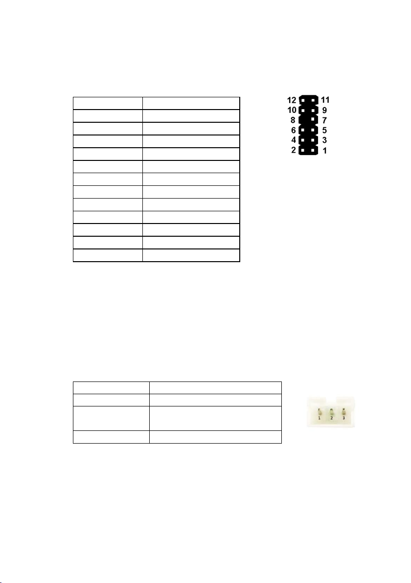
Fan (internal)
The mainboard provides two fan connectors. The CPU fan connector supports PWM fans with 4 pin connection.
Connector details are: 2.54mm (.100") Pitch Vertical Header, with Friction
Lock, 4 (3) Circuits, PC Tail Length: 3.50mm (.138"). Molex Part Nr: 470531000 or similar. The connector follows the Intel “4-Wire Pulse Width
Modulation (PWM) Controlled Fans” specification.
PWM Fan
Pin 1
M1 and M2 Motherboard, User Manual 21
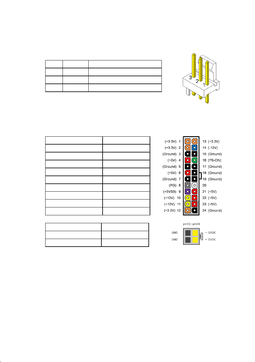
Pin
Signal
Signal Description
1
GND
GND
2
PWR
Operation Voltage 5-12 V
3
Sense
Tachometric signal
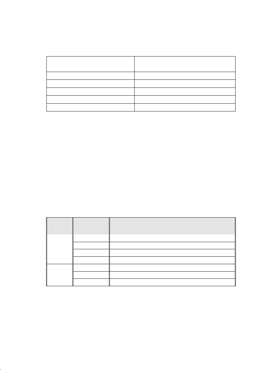
Pin Number
Function
1,2,12,13
+3.3V
3,5,7,15,17,18,19,24
GND
4,6,21,22,23
+5V 8 Power ok
9
5V SB
10, 11
+12V
14
-12V
16
PSON
20
n.c.
Pin Number
Function
1,2
GND
3,4
+12V
The PSU fan connector has 3 pin connection with DC fan speed regulation.
DC Fan
ATX / 12V Power connector (internal)
The mainboard provides a 4 pin and a 24 pin ATX power connector.
A 20 pin ATX power cable can be plugged into the 24 pin connector on the
motherboard, too. In this case the pins 11,12,23 and 24 are not used and
left open. The 4 pin ATX power connector has to be connected to the PSU
anyway, otherwise the motherboard will not work.
22 M1 and M2 Motherboard, User Manual

Voltage regulator
IMVP8: 65 W TDP desktop and server/workstation SKUs
High efficient CPU VR 12.5 Design
XHCI USB controller
The PCH contains an eXtensible Host Controller Interface (XHCI) host controller which supports up to 10 USB 3.0 ports and 14 USB 2.0 ports. This
controller allows data transfers up to 5 Gb/s. The controller supports SuperSpeed (SS), high-speed (HS), full-speed (FS) and low speed (LS) traffic on
the bus.
Windows 7 does not natively support the Skylake USB controller. Therefor
a PS2 keyboard/mouse is recommended for OS setup.
Current BIOS versions include a workaround (USB/PS2 emulation) in order
to use USB keyboard / mouse
during MS Windows 7 installation
For Windows 7 installation a SATA DVD drive has to be used or the XHCI
driver has to be integrated into the installation files to be able to use any
USB drive during installation.
Processor Graphics
DirectX* Video Acceleration (DXVA) support for accelerating video processing.
Full AVC/VC1/MPEG2 HW Decode
Advanced Scheduler 2.0, 1.0, XPDM support.
Windows* 10, Windows* 8, Windows* 8.1, Windows* 7, OSX, Linux* OS
support.
DirectX* 12.0, DirectX* 11.1, DirectX* 11, DirectX* 10.1, DirectX* 10, DirectX* 9 support.
OpenGL* 4.4, OpenGL* 4.0 support.
Max Display Resolutions:
DVI 1920x1200@60Hz
VGA Any resolution and refresh rates are supported from 25 MHz up
to 180 MHz pixel clock rate at 24 bpp, or up to 240 MHz pixel
clock rate at 18 bpp
Display Modes: Single Display, Display Clone, Extended Desktop:
3 Independent displays on M1 only
M1 and M2 Motherboard, User Manual 23

Audio
Default
A
N
B
M
C LD
N
E
N
F
N
G
NH
N
I
L
SP
N
Chip vendor and type: Realtek ALC 671
Audio Codec Ports
Remark: System Beeps are audible on Line_Out1 at Rear Connector.
Supported Sleep States
S0 Normal Operation (“ON”)
S3 Suspend to RAM / “Stand By”
S4 Suspend to Disk / “Hibernation”
S5 Soft Off
24 M1 and M2 Motherboard, User Manual
System wake up
USB
S3
S4/S5 with keyboard only
PS/2
S3
Power button
S3/S4/S5/DS4/DS5
PCIe/PCI PME wakeup
S3/S4/S5
RTC
S3/S4/S5/DS4/DS5
WoL
S3/S4/S5
[Mbit]
Vendor
Type
Macronix
MX25L6450FM2I-10G
Winbond
W25R64FVSIQ
Micron
N25Q064A13ESE4MF
Macronix
MX25L12850FM2I-10G
Winbond
W25R128FVSIQ
Micron
MT25QL128ABA1ESE-MSIT
System wake up is supported from the following devices and power states:
DeepSleep
When no wake up sources are set in BIOS, the system will go into
DeepSleep, when shutting down the system to S5. Most of the onboard
components will be powered off and also the power LED will stay off. In
this case the system power consumption is below 0.5W, depending on PSU
in use.
In this state the System can be switched on by power button or RTC
WakeUp only.
BIOS Flash devices
SPI Flash
Size
64
128
M1 and M2 Motherboard, User Manual 25
 Loading...