

Wincor Nixdorf K1, K2 User Manual

K1 and K2 POS Motherboard
(with BIOS Setup)
User Manual (Edition June 2017)

Overview ........................................................................................ 6
Introduction ....................................................................................... 6
Some Highlights of the K1 and K2 Motherboard ............................... 6
Motherboard Specification ............................................................ 7
Block Diagram .................................................................................... 7
Internal Connectors ........................................................................... 8
Mainboard assembly variants ............................................................ 9
CPU support ....................................................................................... 9
Mainboard internal connectors and onboard features ..................... 9
Serial ports (internal) ..................................................................... 9
USB 2.0 (internal) ......................................................................... 10
Mini PCI Express .......................................................................... 11
Memory (internal) ....................................................................... 12
SATA (internal) ............................................................................. 12
Fan (internal) ............................................................................... 12
Chassis intrusion connector (internal) ......................................... 13
Front panel connector (internal) ................................................. 13
ATX / 12V Power connector (internal) ......................................... 14
LPT (internal) ............................................................................... 15
TPM.............................................................................................. 15
PCI Express Slots (internal) .......................................................... 16
Mainboard onboard connectors with external access ..................... 17
Motherboard I/O shield overview (external) .............................. 17
PanelLink 2.0 (external) ............................................................... 17
VGA (external) ............................................................................. 20
Keyboard / Mouse (external)....................................................... 20
LAN (external) .............................................................................. 20
USB 2.0 / USB 3.0 (external) ........................................................ 20
Audio (external) ........................................................................... 20
Technical Data .............................................................................. 21
Supported Sleep States .................................................................... 22
RAID (K1 Motherboard) ................................................................... 23
Changing the Battery .................................................................... 24
UEFI BIOS Setup ........................................................................... 25
Standard UEFI BIOS Version ............................................................. 25
BIOS Menu Bar ................................................................................. 26
Legend Screen .................................................................................. 26
General Help .................................................................................... 27
Scroll Bar .......................................................................................... 27

Sub-Menu ........................................................................................ 28
Info Screen ....................................................................................... 28
Product Name: ............................................................................ 29
BIOS Version: ............................................................................... 29
Ethernet MAC Address: ............................................................... 29
UUID Info: .................................................................................... 29
System, Main board, Power Supply: ........................................... 29
Main Menu .................................................................................. 30
System Date [MM/DD/YYYY] ....................................................... 30
System Time [XX: XX: XX]............................................................. 30
Processor and Chipset Information ............................................. 30
Advanced Menu ........................................................................... 31
Sub Menu ACPI Settings ............................................................... 31
Enable ACPI Auto Configuration [Enabled] ............................. 32
Sub Menu Trusted Computing ..................................................... 32
Security Device Support [Disable] ............................................... 32
TPM State [Disabled] ................................................................... 32
Pending operation [None] ........................................................... 32
Sub Menu Hardware Configuration ............................................. 33
PCH LAN Controller [Enabled] ..................................................... 33
Launch PXE OpROM policy [Legacy only] .................................... 33
Wake On LAN [Disabled] ............................................................. 33
Wake On Ring [Disabled] ............................................................. 34
Wake On Time [Disabled] ............................................................ 34
Wake On USB/PS2 (S3) [Enabled]................................................ 34
Wake On PCIe Slot [Disabled] ...................................................... 34
Wake On LAN (S3) [Disabled] ...................................................... 34
Wake-on Modes .......................................................................... 35
RMT Button Display1 [Enabled] .................................................. 35
Display Output to COM [Disabled] .............................................. 35
Restore AC Power Loss [Power Off] ............................................ 35
Bootorder Menu [Enabled] ......................................................... 36
VT-d [Enabled] ............................................................................. 36
Sub Menu CPU Configuration ...................................................... 37
Hyper-threading [Enabled] .......................................................... 37
Active Processor Cores [All] ......................................................... 37
Overclocking lock [Disabled] ....................................................... 38
Limit CPUID Maximum [Disabled] ............................................... 38
Execute Disable Bit [Enabled] ...................................................... 38
Intel Virtualization Technology [Enabled] ................................... 38

Hardware Prefetcher [Enabled] ................................................... 38
Adjacent Cache Line Prefetch [Enabled]...................................... 38
CPU AES * [Enabled] .................................................................... 39
Boot performance mode [Max Non-Turbo Performance] ........... 39
EIST [Enabled] .......................................................................... 39
Intel TXT (LT) Support * [Disabled] .............................................. 39
Sub Menu SATA Configuration ..................................................... 40
SATA Controller(s) [Enabled] ....................................................... 40
SATA Mode selection [AHCI] ....................................................... 40
SATA 0, 1, 5 .................................................................................. 41
SATA 4 .......................................................................................... 41
Sub Menu PCH-FW Configuration ................................................ 41
Intel ME (Management Engine) Subsystem ................................ 42
MEBx Type [None] ....................................................................... 42
MDES BIOS State Code [Disabled] ............................................... 42
Sub Menu AMT Configuration ..................................................... 43
Intel AMT [Enabled] ..................................................................... 43
BIOS Hotkey Pressed [Disabled] .................................................. 43
MEBx Selection Screen [Disabled] ............................................... 44
Hide Un-Configure ME Confirmation [Disabled] ......................... 44
MEBx Debug Message Output [Disabled] .................................... 44
Un-Configure ME [Disabled] ........................................................ 44
AMT Wait Timer 0........................................................................ 44
Disable ME [Disabled] .................................................................. 44
ASF [Enabled] .......................................................................... 44
Activate Remote Assistance Process [Disabled] .......................... 44
USB Configure [Disabled] ............................................................. 44
PET Progress [Enabled] ................................................................ 44
WatchDog [Disabled] ................................................................... 45
Sub Menu USB Configuration....................................................... 45
Legacy USB Support [Enabled]..................................................... 46
USB3.0 Support [Enabled] ........................................................... 46
XHCI Hand-off [Enabled] .............................................................. 46
EHCI Hand-off [Enabled] .............................................................. 46
XHCI Mode [Auto] ........................................................................ 46
USB Ports Per-Port Disable Control [Disabled] ............................ 46
USB Mass Storage Driver Support [Enabled] ............................... 46
PORT 60/64 Emulation [Enabled] ................................................ 46
Device Power-up delay [Auto] ..................................................... 47
Sub Menu NTC6106D Super IO Configuration ............................. 47

Sub Menu NTC6106D Super IO Configuration Parallel Port
Configuration ............................................................................... 47
Sub Menu NTC6106D H/W Monitor ............................................ 48
Sub Menu Intel TXT Information.................................................. 49
Sub Menu Serial Port Console Redirection .................................. 49
Console Redirection [Enabled] ................................................. 49
Sub Menu Serial Port Console Redirection Console Redirection
Settings ........................................................................................ 50
Sub Menu Network Stack Configuration ..................................... 51
Sub Menu CMOS .......................................................................... 51
Sub Menu Intel(R) Ethernet Network Connection ....................... 52
Sub Menu Intel(R) Ethernet Network Connection NIC Configuration
..................................................................................................... 52
Chipset Menu ................................................................................... 53
Sub Menu PCH-IO Configuration ............................................. 53
Sub Menu PCH-IO Configuration BIOS Security Configuration53
Sub Menu System Agent (SA) Configuration ............................... 54
Sub Menu System Agent (SA) Configuration Graphics Configuration
..................................................................................................... 54
Boot Menu ....................................................................................... 56
Bootup NumLock State [On] ........................................................ 57
Quiet Boot [Disabled] .................................................................. 57
Fast Boot [Disabled] .................................................................... 57
Boot mode select [LEGACY] ......................................................... 57
Fixed Boot Order Priorities ‘#n’ Boot Device ............................... 57
Security Menu .................................................................................. 58
Administrator Password .............................................................. 58
Intrusion Detection [Disabled] .................................................... 58
Sub Menu Security Menu Secure Boot menu ..................... 59
Save & Exit Menu ............................................................................. 60
Discard Changes and Exit ............................................................ 60
Save Changes and Reset .............................................................. 60
Discard Changes and Reset ......................................................... 60
Restore Defaults .......................................................................... 61
Boot Override .............................................................................. 61
Launch EFI Shell from File System Device ................................... 61
Test Points Codes ............................................................................. 61
Checkpoint Ranges ...................................................................... 61
SEC Phase .................................................................................... 62
PEI Phase ..................................................................................... 62
PEI Beep Codes ............................................................................ 65

DXE Phase .................................................................................... 65
DXE Beep Codes ........................................................................... 68
Abbreviations ............................................................................... 69

We would like to know your opinion on this publication.
Your opinion:
Please send us a copy of this page if you have any constructive criticism.
We would like to thank you in advance for your comments.
With kind regards,
Wincor Nixdorf International GmbH
Documentation R&D BLN
Wohlrabedamm 31
D-13629 Berlin
E-Mail: retail.documentation@wincor-nixdorf.com
Order No.: 010750266921B

K1 and K2 POS Motherboard
User Manual
Edition May 2017

All brand and product names mentioned in this document are trademarks of
their respective owners.
The re production, transmission or use of this document or its contents is not permitted without ex-
press authority. Offenders will be liable for damages. All rights, including rights created by patent
grant or registration of a utility model or design, are reserved. Delivery subject to availability; technical
Copyright © Wincor Nixdorf International GmbH, 2017
modifications possible.


Contents
Overview ....................................................................................... 6
Introduction ....................................................................................... 6
Some Highlights of the K1 and K2 Motherboard ............................... 6
Motherboard Specification ............................................................ 7
Block Diagram .................................................................................... 7
Internal Connectors ........................................................................... 8
Mainboard assembly variants ............................................................ 9
CPU support ....................................................................................... 9
Mainboard internal connectors and onboard features ..................... 9
Serial ports (internal)..................................................................... 9
USB 2.0 (internal) ........................................................................ 10
Mini PCI Express .......................................................................... 11
Memory (internal) ....................................................................... 12
SATA (internal) ............................................................................ 12
Fan (internal) ............................................................................... 12
Chassis intrusion connector (internal)......................................... 13
Front panel connector (internal) ................................................. 13
ATX / 12V Power connector (internal) ........................................ 14
LPT (internal) ............................................................................... 15
TPM ............................................................................................. 15
PCI Express Slots (internal) .......................................................... 16
Mainboard onboard connectors with external access .................... 17
Motherboard I/O shield overview (external) .............................. 17
PanelLink 2.0 (external) ............................................................... 17
VGA (external) ............................................................................. 20
Keyboard / Mouse (external) ...................................................... 20
LAN (external) .............................................................................. 20
USB 2.0 / USB 3.0 (external) ........................................................ 20
Audio (external) ........................................................................... 20
Technical Data ............................................................................. 21
Supported Sleep States .................................................................... 22
RAID (K1 Motherboard) ................................................................... 23
Changing the Battery ................................................................... 24
K1 and K2 Motherboard, User Manual 1

UEFI BIOS Setup ........................................................................... 25
Standard UEFI BIOS Version ............................................................. 25
BIOS Menu Bar ................................................................................. 26
Legend Screen .................................................................................. 26
General Help .................................................................................... 27
Scroll Bar .......................................................................................... 27
Product Name: ............................................................................. 29
BIOS Version: ............................................................................... 29
Ethernet MAC Address: ............................................................... 29
UUID Info: .................................................................................... 29
System, Main board, Power Supply: ............................................ 29
Main Menu .................................................................................. 30
System Date [MM/DD/YYYY] ....................................................... 30
System Time [XX: XX: XX] ............................................................. 30
Processor and Chipset Information ............................................. 30
Advanced Menu ........................................................................... 31
Sub Menu ACPI Settings ............................................................... 31
Enable ACPI Auto Configuration [Enabled] ............................. 32
Sub Menu Trusted Computing ..................................................... 32
Security Device Support [Disable] ............................................... 32
TPM State [Disabled] ................................................................... 32
Pending operation [None] ........................................................... 32
Sub Menu Hardware Configuration ............................................. 33
PCH LAN Controller [Enabled] ..................................................... 33
Launch PXE OpROM policy [Legacy only] .................................... 33
Wake On LAN [Disabled] ............................................................. 33
Wake On Ring [Disabled] ............................................................. 34
Wake On Time [Disabled] ............................................................ 34
Wake On USB/PS2 (S3) [Enabled] ................................................ 34
Wake On PCIe Slot [Disabled] ...................................................... 34
Wake On LAN (S3) [Disabled] ...................................................... 34
Wake-on Modes .......................................................................... 35
RMT Button Display1 [Enabled] ................................................... 35
Display Output to COM [Disabled] .............................................. 35
Restore AC Power Loss [Power Off]............................................. 35
Bootorder Menu [Enabled] .......................................................... 36
VT-d [Enabled] ............................................................................. 36
Sub Menu CPU Configuration ...................................................... 37
Hyper-threading [Enabled] .......................................................... 37
2 K1 and K2 Motherboard, User Manual

Active Processor Cores [All] ......................................................... 37
Overclocking lock [Disabled] ....................................................... 38
Limit CPUID Maximum [Disabled] ............................................... 38
Execute Disable Bit [Enabled] ...................................................... 38
Intel Virtualization Technology [Enabled] ................................... 38
Hardware Prefetcher [Enabled] .................................................. 38
Adjacent Cache Line Prefetch [Enabled] ..................................... 38
CPU AES * [Enabled] .................................................................... 39
Boot performance mode [Max Non-Turbo Performance] .......... 39
EIST [Enabled] .......................................................................... 39
Intel TXT (LT) Support * [Disabled] .............................................. 39
Sub Menu SATA Configuration .................................................... 40
SATA Controller(s) [Enabled] ....................................................... 40
SATA Mode selection [AHCI] ....................................................... 40
SATA 0, 1, 5 .................................................................................. 41
SATA 4 ......................................................................................... 41
Sub Menu PCH-FW Configuration ................................................ 41
Intel ME (Management Engine) Subsystem ................................ 42
MEBx Type [None] ....................................................................... 42
MDES BIOS State Code [Disabled] ............................................... 42
Sub Menu AMT Configuration ..................................................... 43
Intel AMT [Enabled]..................................................................... 43
BIOS Hotkey Pressed [Disabled] .................................................. 43
MEBx Selection Screen [Disabled] ............................................... 44
Hide Un-Configure ME Confirmation [Disabled] ......................... 44
MEBx Debug Message Output [Disabled] ................................... 44
Un-Configure ME [Disabled] ........................................................ 44
AMT Wait Timer 0 ....................................................................... 44
Disable ME [Disabled] ................................................................. 44
ASF [Enabled] .......................................................................... 44
Activate Remote Assistance Process [Disabled] .......................... 44
USB Configure [Disabled] ............................................................ 44
PET Progress [Enabled] ................................................................ 44
WatchDog [Disabled] ................................................................... 45
Sub Menu USB Configuration ...................................................... 45
Legacy USB Support [Enabled] .................................................... 46
USB3.0 Support [Enabled] ........................................................... 46
XHCI Hand-off [Enabled].............................................................. 46
EHCI Hand-off [Enabled] .............................................................. 46
XHCI Mode [Auto] ....................................................................... 46
K1 and K2 Motherboard, User Manual 3

USB Ports Per-Port Disable Control [Disabled] ............................ 46
USB Mass Storage Driver Support [Enabled] ............................... 46
PORT 60/64 Emulation [Enabled] ................................................ 46
Device Power-up delay [Auto] ..................................................... 47
Sub Menu NTC6106D Super IO Configuration ............................. 47
Sub Menu NTC6106D Super IO Configuration
Parallel Port Configuration ...................................................... 47
Sub Menu NTC6106D H/W Monitor ............................................ 48
Sub Menu Intel TXT Information .................................................. 49
Sub Menu Serial Port Console Redirection .................................. 49
Console Redirection [Enabled] ................................................. 49
Sub Menu Serial Port Console Redirection Console Redirection
Settings ........................................................................................ 50
Sub Menu Network Stack Configuration ...................................... 51
Sub Menu CMOS .......................................................................... 51
Sub Menu Intel(R) Ethernet Network Connection ....................... 52
Sub Menu Intel(R) Ethernet Network Connection
NIC Configuration .................................................................... 52
Chipset Menu ................................................................................... 53
Sub Menu PCH-IO Configuration ............................................. 53
Sub Menu PCH-IO Configuration
BIOS Security Configuration .................................................... 53
Sub Menu System Agent (SA) Configuration ................................ 54
Sub Menu System Agent (SA) Configuration
Graphics Configuration ........................................................... 54
Boot Menu ....................................................................................... 56
Bootup NumLock State [On] ........................................................ 57
Quiet Boot [Disabled] .................................................................. 57
Fast Boot [Disabled]..................................................................... 57
Boot mode select [LEGACY] ......................................................... 57
Fixed Boot Order Priorities ‘#n’ Boot Device ............................... 57
Security Menu .................................................................................. 58
Administrator Password .............................................................. 58
Intrusion Detection [Disabled] .................................................... 58
Sub Menu Security Menu Secure Boot menu ..................... 59
Save & Exit Menu ............................................................................. 60
Discard Changes and Exit ............................................................. 60
Save Changes and Reset .............................................................. 60
Discard Changes and Reset .......................................................... 60
Restore Defaults .......................................................................... 61
4 K1 and K2 Motherboard, User Manual

Boot Override .............................................................................. 61
Launch EFI Shell from File System Device ................................... 61
Test Points Codes ............................................................................. 61
Checkpoint Ranges ...................................................................... 61
SEC Phase .................................................................................... 62
PEI Phase ..................................................................................... 62
PEI Beep Codes ............................................................................ 65
DXE Phase .................................................................................... 65
DXE Beep Codes .......................................................................... 68
Abbreviations .............................................................................. 69
K1 and K2 Motherboard, User Manual 5

Overview
Introduction
This manual describes the features of two variants of a Motherboard based
on the Intel 8 series chipset Q87 and H81, formerly known as Lynx Point.
Some Highlights of the K1 and K2 Motherboard
4th Generation Intel® Core™ Processors, formerly known as Haswell
Intel 8 series chipset Q87 and H81, formerly known as Lynx Point
CPU integrated graphic controller up to Intel® HD Graphics 4600,
depending on used processor
AMT 9.1 support at K1 motherboards
2x Panellink 2 interfaces
1x VGA interface
Gigabit LAN onboard (Intel® Ethernet Connection; Q87: I217-LM,
H81: I217-V)
3 SATA ports (Q87: 3xSATA III, H81: 2x SATA III + 1x SATA II)
2x DDR3 SODIMM sockets, supporting up to 16GB (2x8GB) at
1600MHz. Only ~3GB available for 32bit OS
1x PCI Express x16 gen3
2x PCI Express x1 gen2
6 COM ports. COM1 is unpowered, COM2-6 have the option to be
powered
1 LPT port
MiniPCIe socket (full size) supporting the WN NVRAM module
2 USB3.0 ports
up to 10 USB2.0 ports (H81: 6 ports)
TFT- displays without DDC are not supported.
6 K1 and K2 Motherboard, User Manual
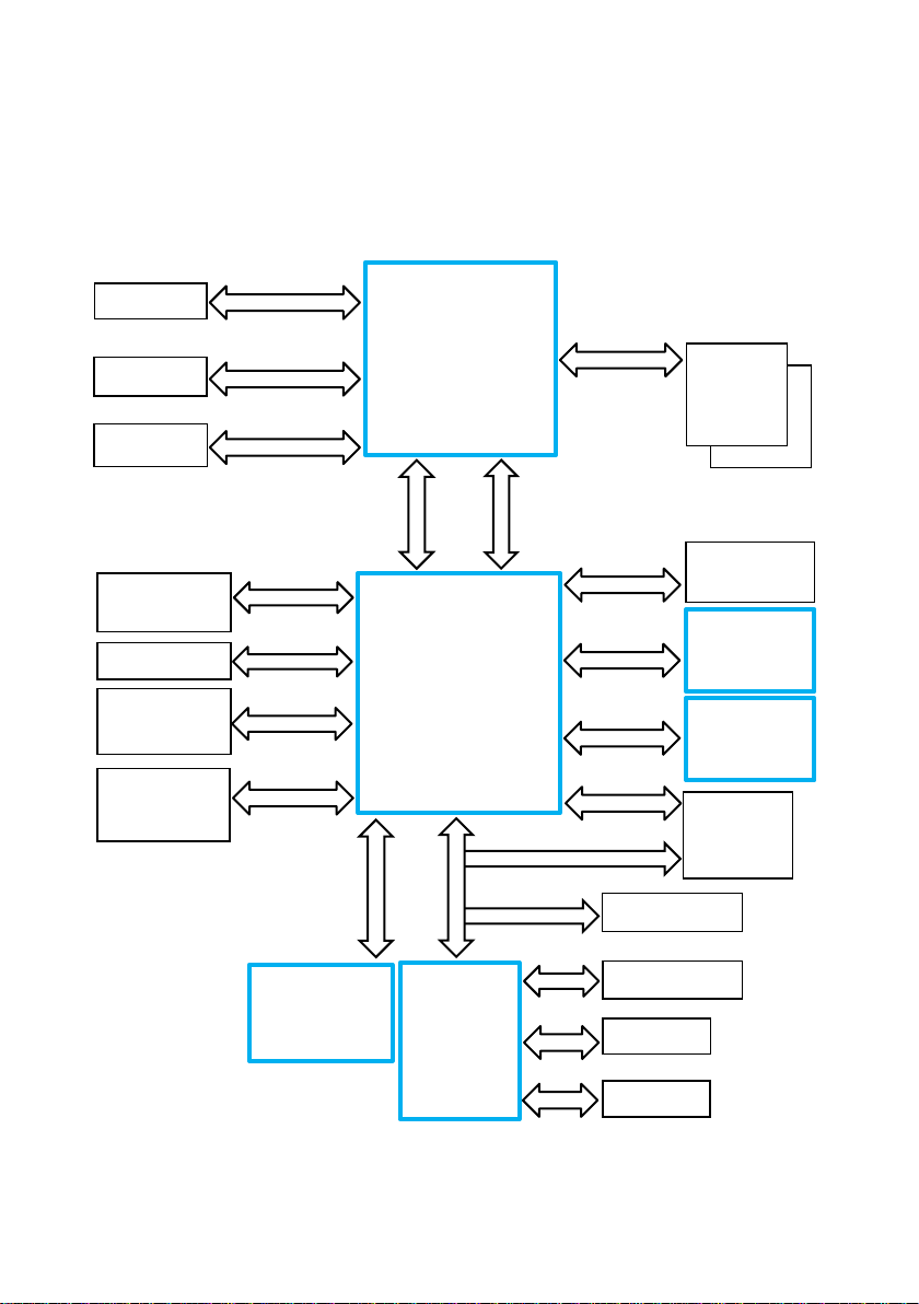
Motherboard Specification
Panel Link 2
Level Shifter PI3VDP411
Panel Link 2
DMI
FDI
PCI Express x1
SATA II/III
USB2.0
USB3.0
3x SATA Ports
HD Audio Link
PCI Express x1
HD Audio
ALC662
SPI
COM
LPT
Up to 6x COM
LPC
PCI Express x1
TPM Header
PS/2
PS/2
Level Shifter PI3VDP411
Block Diagram
PCIe x16 Slot
2x PCIe x1 Slot
Up to 10 USB2.0
Ports
2x USB3.0 Ports
PCI Express x16
BIOS
64/128Mbit
LGA 1150
Haswell + Haswell Re-
fresh CPU
65W TDP max.
Lynx Point PCH
Q87 / H81
LPC
SIO
NCT6106D
Dual Channel DDR3
VGA
LPC
LPT
2x DDR3
SODIMM
Socket
VGA
Codec
1Gb LAN
I217LM/I217V
miniPCIe
K1 and K2 Motherboard, User Manual 7
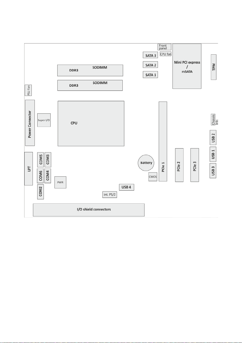
Internal Connectors
8 K1 and K2 Motherboard, User Manual

Mainboard assembly variants
CPU CPU#
#CPU
core
#Threads
GHz
Core
GHz
GFX
Cache
size
TDP
[W]
i5
i5-4570TE
2 4 2.7 (3.3)
0.35 (1)
4MB
35
i5
i5-4570S
4 4 2.9 (3.6)
0.35(1.15)
6MB
65
i3
i3-4330TE
2 4 2.4
0.35 (1)
4MB
35
i3
i3-4330
2 4 3.5
0.35 (1.15)
4MB
54
Pentium
G3320TE
2 2 2.3
0.35 (1)
3MB
35
Pentium
G3420
2 2 3.2
0.35 (1.15)
3MB
53
Celeron
G1820TE
2 2 2.2
0.35 (1)
2MB
35
Celeron
G1820
2 2 2.7
0.35 (1.05)
2MB
53
As mentioned above there are two motherboard variants: The K1 board
with Q87 chipset supporting AMT and RAID and the K2 board with H81
chipset as value edition supporting lesser features.
CPU support
Mainboard internal connectors and onboard features
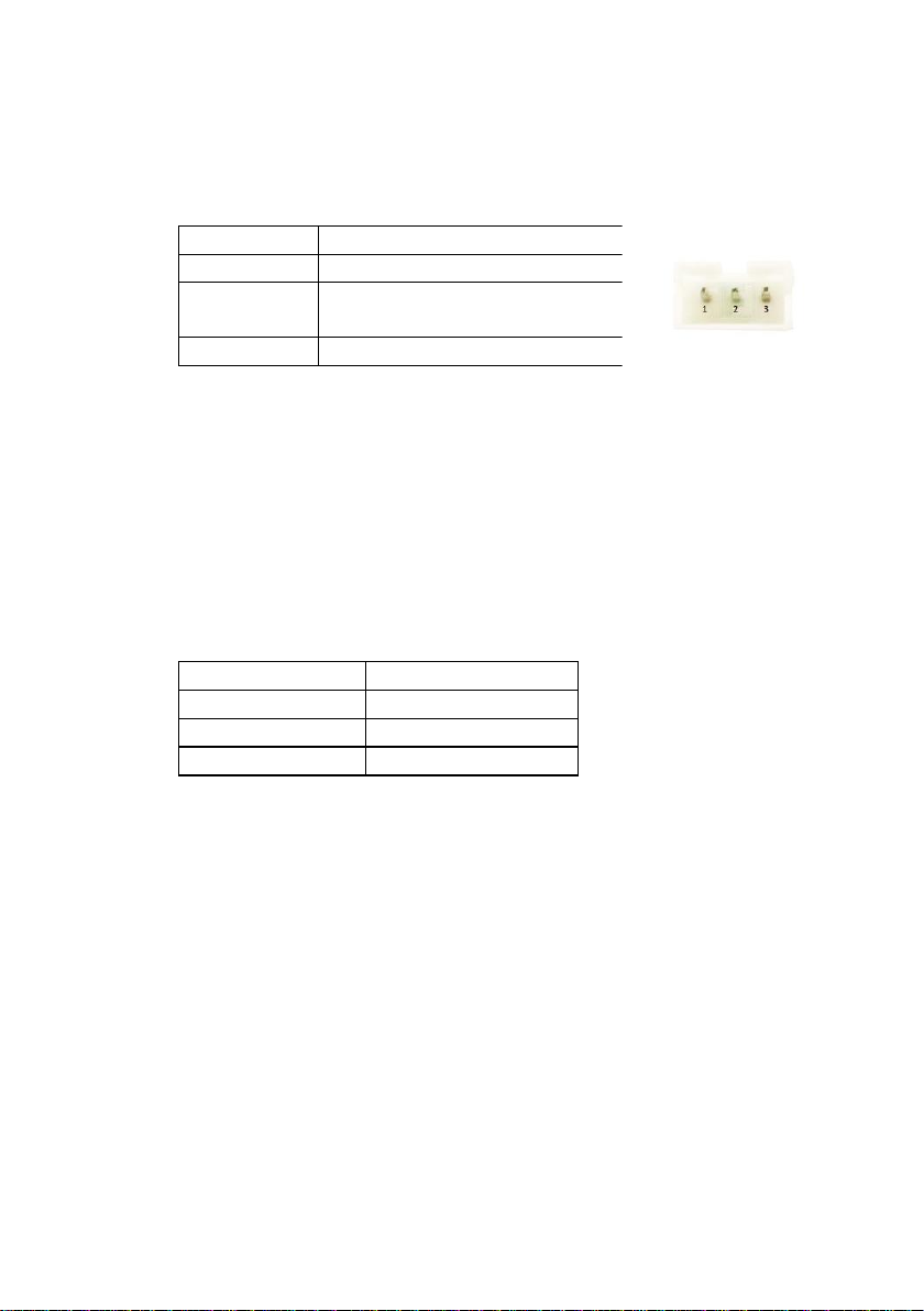
Serial ports (internal)
K1 and K2 Motherboard, User Manual 9
COM2 -6 are configurable to standard or powered COM ports with an internal COM cable option (max current for powered COM: single port
300mA@5V; all ports together not more than 500mA@5V; single port
600mA@12V; all ports together not more than 900mA@12V).
Maximum voltage drop on 12V is 300mV, on 5V it is 150mV at full load.
This output is designed according to UL regulations and is protected by a
self-resettable fuse.
COM1 is a standard 9 pin DSUB connector in I/O shield supporting “WAKE
On Ring” functionality.
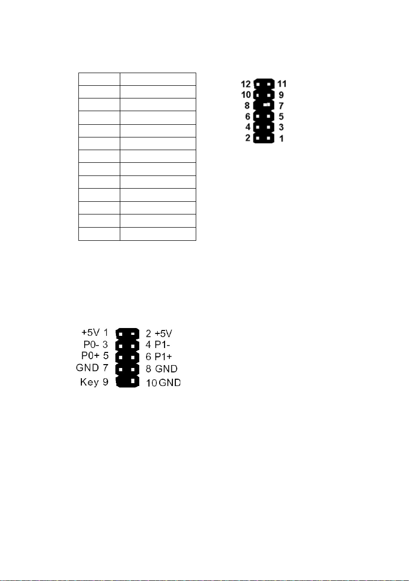
2x 6 pin header, 2.54 mm pitch
Pin
Signal
1
DCD 2 RX
3
TX
4
DTR 5 GND
6
DSR 7 RTS 8 CTS
9
RI
10
Key Pin
11
+5 V
12
+12 V
USB 2.0 (internal)
8 USB ports at K1 board and 4 USB ports at K2 are routed to 10pin double
row headers with 2.54 mm pitch. Each header provides 2 ports. These
headers are intended to connect optional front USB modules or USB hubs.
Two USB ports share one fuse. USB port 11 at header USB3 (pins 1,3,5,7)
is shared with PCIe x1 connector PCIE3 (pins A5 to A8) for USB uplink
connection for the "Retail Card".
10 K1 and K2 Motherboard, User Manual

Mini PCI Express
Pin
Function
Pin
Function
1
WAKE
2
VCC3
3
n.c. 4 GND
5
n.c. 6 VCC 1.5V
7
CLKRQ#
8
FRAME#
9
GND
10
LAD3
11
REFCLK-
12
LAD2
13
REFCLK+
14
LAD1
15
GND
16
LAD0
17
SUSCLK 32KHz
18
GND
19
CLK 33MHz
20
n.c.
21
GND
22
RESET#
23
PCIE_RX- / SATA +B
24
3VSB
25
PCIE_RX+ / SATA -B
26
GND
27
GND
28
VCC 1.5V
29
GND
30
SMB_CLK
31
PCIE_TX- / SATA -A
32
SMB_DATA
33
PCIE_TX+ / SATA +A
34
GND
35
GND
36
n.c. (USB-)
37
GND
38
n.c. (USB+)
39
VCC3
40
GND
41
VCC3
42
n.c.
43
GND
44
n.c.
45
n.c.
46
n.c.
47
n.c.
48
VCC 1.5V
49
n.c.
50
GND
51
mSATA presence detect
52
VCC3
The mainboard provides a full size mini PCI Express (rev.1.1) / mSATA
connector. It is placed on top, thus being accessable without removing
other components. It supports LPC signals including serial interrupts. Auto
detection by mSATA presence detect supports automated switch between
mSATA and PCIe functionality (PCIe functionality only supported in
conjunction with Q87 chipset according to mini PCI Express Standard
Rev 1.1). The K1 motherboard supports PCIe and mSATA functionality,
the K2 motherboard supports mSATA functionality only.
Connector type: Standard MiniPCIe 1.1 connector full size
K1 and K2 Motherboard, User Manual 11
Memory (internal)
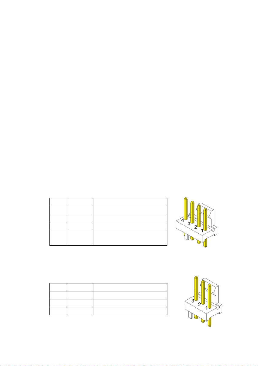
Pin
Signal
Signal Description
1
GND
GND
2
12 V
Fan operation voltage
3
Sense
Tachometric signal
4
Control
PWM control signal (only
4 pin connector)
Pin
Signal
Signal Description
1
GND
GND
2
PWR
Operation Voltage 6-12 V
3
Sense
Tachometric signal
The mainboard provides two DDR3 SODIMM sockets supporting up to
16GB in dual channel mode. The horizontal mounting of the SODIMM sockets ensures an optimal air flow.
SATA (internal)
The mainboard provides three standard SATA ports. The ports SATA1
(white) and SATA2 (blue) supporting SATA III connectivity speed.
Port SATA3 (black) supports SATA III speed at K1 board, and SATA II
speed at K2 board. The RAID functionality is only supported by the K1
motherboard.
Fan (internal)
The mainboard provides two fan connectors. The CPU fan connector supports PWM fans with 4 pin connection.
Connector details are: 2.54mm (.100") Pitch Vertical Header, with Friction
Lock, 4 (3) Circuits, PC Tail Length: 3.50mm (.138"). Molex Part Nr: 470531000 or similar. The connector follows the Intel “4-Wire Pulse Width
Modulation (PWM) Controlled Fans” specification.
PWM Fan
The PSU fan connector has 3 pin connection with DC fan speed regulation.
DC Fan
12 K1 and K2 Motherboard, User Manual
Chassis intrusion connector (internal)
Pin Number
Function
1
GND
2
Intrusion input (switch to GND
if chassis is open)
3
n.c.
Power Status
Power LED
S0
Green
S3
Green blinking
S4, S5
Orange
The mainboard supports a chassis intrusion connector.
Type: 3 pin shrouded header, B3B-PH-K-S (JST) or equivalent.
Front panel connector (internal)
The mainboard supports a front panel connector to support service
elements (like POWER ON pushbutton, HDD and power LEDs).
The Power LED at the chassis front connected to this front panel header
is green when system is powered on (S0). During Stand By (S3) it blinks
green and when system is in hibernation (S4) or powered down (S5) the
LED is orange.
The BIOS is able to disable the power button. This feature is automatically
enabled when "Follow AC power" is selected within the BIOS setup. Then it
is not possible to switch off the system by the power button, even when
pressed longer than 4s. But when the OS is shut down correctly, system
can be switched on again by the power button.
The front panel header also supports speaker connection.
K1 and K2 Motherboard, User Manual 13
Type: 2x6 pin header, 2.54 mm pitch.
Pin Number
Function
1
Power switch +
2
Reset switch +
3
Power switch -
4
Reset switch -
5
Power LED +
6
Speaker -
7
Power LED -
8
Coding
9
HDD LED +
10
GND
11
HDD LED -
12
Speaker +
Pin Number
Function
1,2,12,13
+3.3V
3,5,7,15,17,18,19,24
GND
4,6,21,22,23
+5V 8 Power ok
9
5V SB
10, 11
+12V
14
-12V
16
PSON
20
n.c. Pin Number
Function
1,2
GND
3,4
+12V
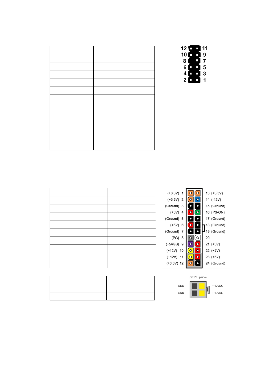
ATX / 12V Power connector (internal)
The mainboard provides a 4 pin and a 24 pin ATX power connector.
A 20 pin ATX power cable can be plugged into the 24 pin connector on the
motherboard, too. In this case the pins 11,12,23 and 24 are not used and
14 K1 and K2 Motherboard, User Manual
left open. The 4 pin ATX power connector has to be connected to the PSU
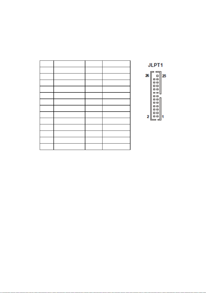
Pin
Function
Pin
Function
1
STR#
14
GND
2
AFD#
15
D6 3 D0
16
GND
4
ERR#
17
D7 5 D1
18
GND
6
PINIT#
19
ACK#
7
D2
20
GND
8
LPT_SLIN#
21
BUSY
9
D3
22
GND
10
GND
23
PE
11
D4
24
GND
12
GND
25
SLCT
13
D5
26
Key
anyway, otherwise the motherboard will not work.
LPT (internal)
Connector type: 26 pin shrouded header, 2.54mm pitch
TPM
The mainboard supports one dedicated TPM port. This connector slot is
placed on top and is accessable without removing any other components.
K1 and K2 Motherboard, User Manual 15
 Loading...