

Wincor Nixdorf J1-CPU User Manual
POS Motherboard
J1-CPU
User Manual

We would like to know your opinion on this publication.
Please send us a copy of this page if you have any constructive criticism.
We would like to thank you in advance for your comm ent s.
With kind regards,
Wincor Nixdorf International GmbH
Documentation R&D SAT22
Wohlrabedamm 31
D-13629 Berlin
E-Mail: retail.documentation@wincor-nixdorf.com
Order No.: 01750228406°
Your opinion:

POS Motherboard
J1-CPU
User Manual
Edition November 2012

All brand and product names mentioned in this document are trademarks of their
respective owners.
Copyright © Wincor Nixdorf International GmbH, 2012
The reproduction, transmission or use of this document or its contents is not permitted without
express authority.
Offenders will be liable for damages. All rights, including rights created by patent grant or
registration of a utility model or design, are reserved.
Delivery subject to availability; technical modif ications poss i bl e.
Refer to protection notice ISO 16016

Contents
Overview ...................................................................................................... 1
Introduction.................................................................................................... 1
Highlights of Cedar Trail J1 Motherboard ...................................................... 1
Motherboard Specification ......................................................................... 3
Motherboard Mechanical Arrangement ......................................................... 4
Motherboard PCB Dimension ........................................................................ 5
External I/O Connector .................................................................................. 5
Internal I/O Connector ................................................................................... 6
Jumper Setting .............................................................................................. 7
Maximum Power Consumption ...................................................................... 7
Typical Power Consumption .......................................................................... 7
Maximum Current Rating for external Peripherals ......................................... 8
Supported Power Modes (Sx) ....................................................................... 8
Thermal Management ................................................................................... 9
CPU Support ................................................................................................. 9
Memory Support ............................................................................................ 9
Graphics Subsystem ................................................................................... 10
System Clock Generator ............................................................................. 11
Gigabit LAN Interfac e .................................................................................. 11
Super I/O Controller .................................................................................... 11
SATA II Interface ......................................................................................... 12
CPU Fan and System Fans ......................................................................... 12
Audio ........................................................................................................... 12
USB Interface .............................................................................................. 13
Serial Interfaces COM 1-6 ............................................................................ 13
PS/2 Keyboard Interface ............................................................................. 13
Front Panel Interface ................................................................................... 14
Cash Drawer Interface I/O 310h .................................................................. 14
Intrusion Detect Interface ............................................................................ 14
TPM ............................................................................................................. 14
System Beeper ............................................................................................ 15
PCIe Slot ..................................................................................................... 15
PCI Slot ....................................................................................................... 15
Mini PCIe Slot .............................................................................................. 15
RMT Feature ............................................................................................... 15
Connector and Pin Assignments ............................................................. 16
External Connectors .................................................................................... 16
PS/2 Connector ...................................................................................... 16
Gigabit LAN Connector ........................................................................... 16
USB Connectors ..................................................................................... 17
COM1 Connector .................................................................................... 17

COM2*-6* Connectors ............................................................................ 18
DVI-I Connector ...................................................................................... 19
DisplayPort Connector ............................................................................ 20
Audio Connector ..................................................................................... 21
Connectors and Headers for internal Connection ........................................ 21
SATA ....................................................................................................... 21
USB Header ............................................................................................ 22
Front Panel Interface Connector ............................................................. 23
Cash Drawer Interface Connector ........................................................... 23
Fan Connector (with FAN speed control) ................................................ 24
Intrusion Interface ................................................................................... 24
ATX Power .............................................................................................. 24
PCI Express x1 ....................................................................................... 25
PCI .......................................................................................................... 25
RMT ........................................................................................................ 28
Internal Speaker out ................................................................................ 28
Mini PCIe ................................................................................................ 28
Technical Data ........................................................................................... 31
Changing the Battery ................................................................................ 34
Addendum: Sleep States .......................................................................... 35
UEFI BIOS Setup ........................................................................................ 36
Standard UEFI BIOS Version ...................................................................... 36
BIOS Menu Bar ....................................................................................... 37
Legend Screen ........................................................................................ 37
General Help ........................................................................................... 38
Scroll Bar ................................................................................................ 38
Sub-Menu ............................................................................................... 38
Info Screen .................................................................................................. 39
Product Name: ........................................................................................ 40
BIOS Version: ......................................................................................... 40
BIOS Date: .............................................................................................. 40
Ethernet MAC Address: .......................................................................... 40
Windows XP Graphics Support: .............................................................. 40
UUID Info: ............................................................................................... 40
System, Main board, Power Supply: ....................................................... 40
Main Menu ................................................................................................... 41
System Date [XX/XX/XXXX] ................................................................... 41
System Time [XX: XX: XX] ...................................................................... 41
Advanced Menu ........................................................................................... 41
Advanced Menu ........................................................................................... 42
Sub Menu Trusted Computing ............................................................ 42
Security Device Support [Enable] ........................................................ 42
TPM State [Disable] ............................................................................. 42
Pending operation [None] ................................................................... 42
Advanced Menu ........................................................................................... 43
Sub Menu > Hardware Configuration ...................................................... 43

Intel GMCH Configuration ................................................................... 46
Advanced Menu .......................................................................................... 47
Sub Menu CPU Configuration ............................................................. 47
Advanced Menu .......................................................................................... 48
Sub Menu SATA Configuration ........................................................... 48
Advanced Menu .......................................................................................... 49
Sub Menu USB Configuration ............................................................. 49
Advanced Menu .......................................................................................... 50
Sub Menu IO Port Configuration ......................................................... 50
Advanced Menu .......................................................................................... 51
Sub Menu H/W Monitoring .................................................................. 51
Boot Menu ................................................................................................... 52
‘#n’ Boot Device ...................................................................................... 52
Security Menu ............................................................................................. 53
Administrator Password .......................................................................... 53
Intrusion Detection [Disabled] ................................................................. 53
Save & Exit Menu ........................................................................................ 54
Save Changes and Exit .......................................................................... 54
Discard Changes and Exit ...................................................................... 54
Save Changes and Reset ....................................................................... 54
Discard Changes and Reset ................................................................... 55
Restore Defaults ..................................................................................... 55
Boot Override .......................................................................................... 55
Launch EFI Shell from filesystem device ................................................ 55
Test Points Codes ....................................................................................... 56
Checkpoint Ranges ..................................................................................... 56
SEC Phase .................................................................................................. 56
PEI Phase ................................................................................................... 57
PEI Beep Codes .......................................................................................... 60
DXE Phase .................................................................................................. 60
DXE Beep Codes ........................................................................................ 62
Abbreviations ............................................................................................ 63


POS Motherboard with J1-CPU 1
Overview
Introduction
This specification describes the features of a Motherboard based on the
INTEL Cedarview processor and NM10 chip set in mITX form factor.
This Cedar Trail Motherboard (J1 for short) is designed for integration
into Wincor BEETLE / X plus sealed systems and other POS systems like
BEETLE /i8A, the BEETLE /SII+ family and t he EPC ATS.
Highlights of Cedar Trail J1 Motherboard
Intel ATOM processor Cedarview (dual core), min. 2GHz
Integrated Graphics Core supporting VGA+DVI (DVI-I) , Display Port
HDD SATA II inter face (2 ports)
Fan-less Motherboard design, supports chassis fan with automatic PWM
speed control
Intel Gigabit LAN on board
Two DDR3 SDRAM (SO-DIMM) socket, up to 4GB / 1066MHz supported
One PCI Express slot
One PCI slot (supports riser card only)
One mini PCI Express slot with LPC support for TPM and NVRAM
module
6 COM ports (5 ports have the option to be powered COM interfaces)
Onboard RJ11 remote control interface RMT (power save button)
8 USB ports
PS/2 connector, supports keyboard and mouse via Y-cable
Cash Drawer support on boar d

2 POS Motherboard with J1-CPU
Intel HD audio controller with Realtek audio codec supporting micro-
phone, line in and amplified speaker out
Optional NVRAM and TPM module support via mini PCIe
OS support includes Windows 7 (32 Bit), Windows 8 (32 Bit),
XP (32 Bit), Linux
Long term availability (5 years; Intel embedded roadmap)
POS Motherboard with J1-CPU 3
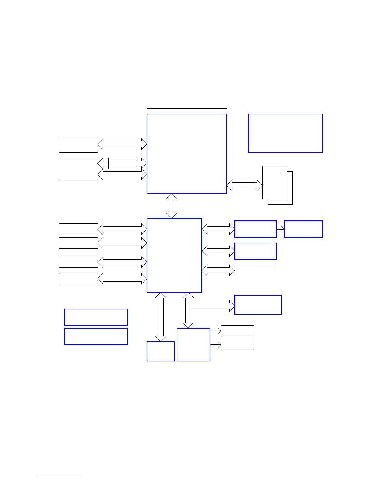
Motherboard Specification
LVDS
Video (LVDS)
NM10
D2700 / 2.13GHz
internal digital
RMT connecto r RJ11
3.3VSB, 1.8V, 1. 5V , 1.05V
mini PCIe Slot
PCIe x1
DVI level s hifter
Block Di agram
System Power
SPI
Cas h Drawer C PL D
PCIe x1
LAN 1 GB
Intel 82583V
USB Port 1~8
HD Audio Codec
ALC262
SATA2
Module
SATA-II 1,2
2 DDR III
Intel ATOM Processor
DDRIII
VRD 12
SODIMM
DDR3 800/1066MHz, 4GB max
1-Phase PWM
RGB
PCI express x1
PCIe x1 Slot
LPC SIO
Tiger Point
SPI
LPC
USB2.0
DMI
5 COM*
HD Audio Link
1 COM
Audio AMP
TEA2025B
5M40ZE64
Flash ROM
PS/2
KEYBOARD
Clock
Cedar View-D
analog Video
DP
DP
digital Video
Digital and
DVI-I
PCI 32Bit 33MHz
PCI riser slo t
ATX inp ut
4 POS Motherboard with J1-CPU
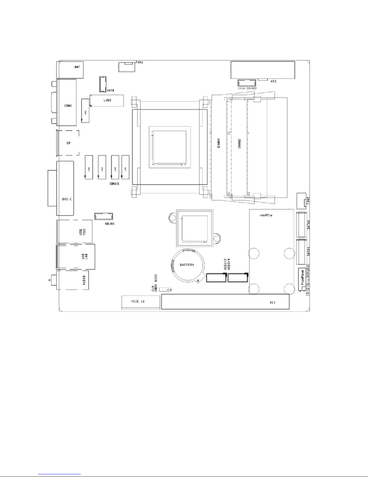
Motherboard Mechanical Arrangement
POS Motherboard with J1-CPU 5
Motherboard PCB Dimension
J1 motherboard (including I/O shield) follows mITX standard and therefore
PCB mechanical dimension is 170mm by 170mm.
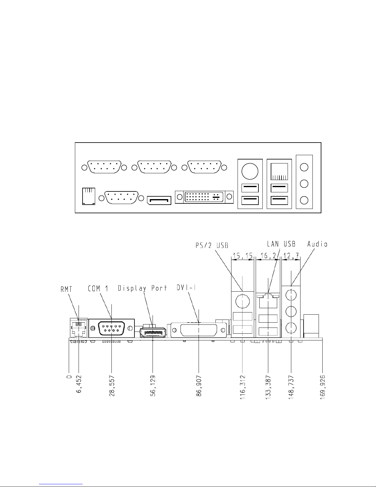
External I/O Connector
External I/O connectors are ar ranged as illustrated here:
COM1
COM3COM2
LAN/USB
AUDIO
K/M/USB
COM4
RMT
DVI-I
DP

6 POS Motherboard with J1-CPU
Interface Connector Type
COM1 9 pin D-sub male
DVI + VGA DVI-I
RMT RJ11
Keyboard, Mouse, USB 6 pin Mini Din + stacked dual USB series A
LAN, USB RJ45 Ethernet + stacked dual USB series A
Display Port Standard Display Port connector
AUDIO Speaker Out 3,5 mm female (green)
AUDIO Line In 3,5 mm female (violet)
AUDIO Microphone 3,5 mm female (blue)
Internal I/O Connector
Interface Connector Type
DDR3 SODIMM 204 pin micro edge connector
Hard disk (SATA) 2pcs 7 pin Standard SATA headers
3.3V, 5V, 12V supply ATX 20 pin power connector
USB port 1-4 2x5 pin headers, 2.54 mm
COM* 2-6 2x7 pin headers (2.0 mm shrouded)
FAN 2pcs 4 pin
PCIe standard PCIe x1 connector
PCI standard PCI connector
Mini PCIe Full size and half size mini PCIe connector
Front panel 2x6 pin header, 2.54 mm
Chassis intrusion 3 pins header (2.0 mm shrouded)
Cash drawer 6 pins header (2.0 mm shrouded)
Internal speaker 2 pins header (2.0 mm)

POS Motherboard with J1-CPU 7
Jumper Setting
Jumper Connector Type Setting
JP1 CMOS clear 1-2 default, 2-3 CMOS clear
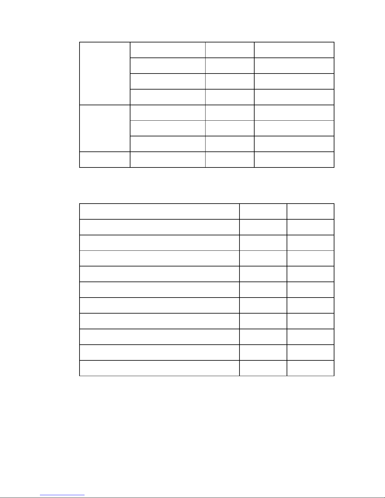
Maximum Power Consumption
The J1 motherboard is powered by 3.3V, 5V, 5V stand by, 12V and -12V
from a standard ATX power supply. The maximum current is specified as
follows, this does not include external connected peripherals.
Voltage I max P
3.3V 0.5A 1.5W
5V 0.2A 1W
5VSB 0.5A 2.5W
12V 1.5A 18W
-12V 0.1A 1.2W
Typical Power Consumption
The J1 motherboard’s typical power consumption is listed below. Test
condition is motherboard and no peripherals, keyboard, mouse, USB
devices, COM port not connected, Ethernet link and memory configuration
as mentioned below, Windows 7, 32Bit idle.
Voltage Condition I P
3.3V 0.3A 1W
5V 0.15A 0.75W
5VSB (S0)
S0 No Ethernet link 0.12A 0.6W
S0 100MBit 0.18A 0.9W
S0 1GB 0.35A 1.75W
8 POS Motherboard with J1-CPU
S3 (no WOL) 0.12A 0.6W
S3 (WOL 10MBit) 0.15A 0.75W
S5 (no WOL) 0.055A 0.3W
S5 (WOL 10MBit) 0.11A 0.55W
12V
2GB 0.75A 9W
4GB 0.85A 10.2W
Intel Max Power 1.35A 16.2W
-12V 0.09A 1.1W
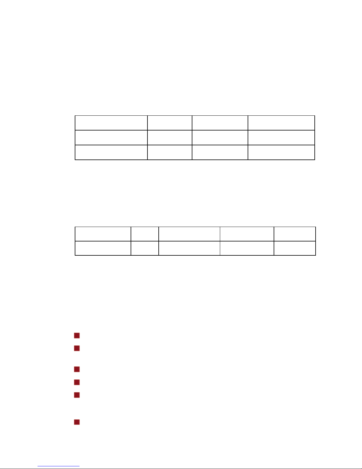
Maximum Current Rating for external Peripherals
Interface Voltage I /P max
Powered COM (COM 2-6 summery) 5V 1A
Powered COM single port 5V 0.3A
Powered COM (COM 2-6 summery) 12V 1A
Powered COM single port 12V 0.6A
USB, single port 5V 0.5A
USB, all ports summary 5V 2A
PS/2 5V 0.5A
DVI, VGA 5V 0.1A
Display Port 3.3V 0.1A
PCI or PCIe card all 10W
Supported Power Modes (Sx)
J1 Motherboard supports power states S0, S3, S4 and S5. Wake up events
from sleep states are supported from USB ports, COM1 ring indicator, internal CMOS clock, PS/2 Keyboard or Mouse and Ethernet.
Power management supp orts AC PI 3.0 and APM1.2
POS Motherboard with J1-CPU 9
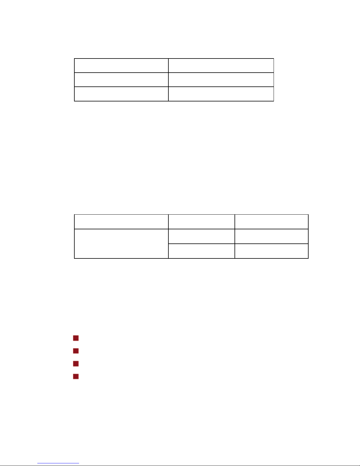
Thermal Management
The J1 Motherboard supports 1 FAN connector with 4 pin PWM fan type.
The 2
nd
FAN connector is reserved for power supply fan and detects rotating
speed of PSU fan.
Supported CPUs and its TDP and max imum junction temperature:
CPU TDP Idle power Max Tj
Cedarview 10W 2W typ. 100 °C
NM10 2W 1W 115 °C
CPU Support
Due to the fact Atom CPU comes in a BGA package it is soldered to PCB
and cannot be changed.
Processor Core Clock Speed Footprint Max TDP
CedarVIEW 2 2.13GHz FCBGA 10W
Memory Support
The motherboard has 2 SODIMM sockets supporti ng sing le chan nel, unbuffered, no ECC DDR3 SDRAM.
Supports total memory size of 1 GB, 2 GB and 4 GB max
Supports 1-Gb, 2-Gb and 4-Gb densities technologies
(for both x8 and x16)
DRAM Chip Data Width: x8, x16
Banks / DRAM Chip: 8
Support DIMM page size of 4KB and 8KB
The motherboard supports the following memory features:
800 /1066 MHz unbuffered SDRAM SO-DIMM

10 POS Motherboard with J1-CPU
Non-ECC
1.5V voltage rating
BIOS automatically detects memory type, size, and speed
If higher frequency memory modules than 1066MHz are used, the frequency
will be limited to 1066MHz automatically.
Warning
SODIMM2 (lower socket) must always be populated first!
Graphics Subsystem
Graphics support is via the internal grap hic s acc eler ator of the Cedarview
processor to provide dual independent display.
Main features of integrated GPU are:
640 MHz render clock frequency
Seven display planes, Display Plane A, B, Display Sprite C (can be
connected to either pipes), Display OV (can be connected to either
pipes), Cursor A, Cursor B and VGA
Two display pipes, Pipe A and B support the dual independent displays
Max Pixel Clock: DDI: 2x 4, 1.62GHz, 2.7GHz; VGA: up to 350MHz
DVI-I, Display Port, CRT/DAC supported, independent DDC for all
interfaces
External monitor: CRT/DAC via DVI-I, DVI, Display Port
Support Intel® Display Power Saving Technology (Intel® DPST) 4.0
No Frame Buffer Compensation (FBC)
No TV -Out
Regarding driver related features please see latest information on Intel’s
homepage.
The analogue VGA port utilizes an integrated 350MHz RAMDAC capable of
driving a standard progressive scan monitor resolution up to 1920 x 1200 at
60Hz.

POS Motherboard with J1-CPU 11
Signal
Voltage Level
R,G,B 0.7VP-P @75OHM
HSYNC, VSYNC 5.0V
DDC Channel
Open drain, 5.0V tolerant
The digital DVI interface is converted from DP interface with active level
shifter IC and supports a maximum resolution of 1920 x 1200 pixels.
The Display Port interface supports a maximum resolution of 2560 x 1600
pixels.
System Clock Generator
The clock generator is conforming to CK505 spe cif icat ion and Cedar View
demands and made by IDT ICS9VRS4339.
Gigabit LAN Interface
Gigabit LAN interface is provided thru a cost effective PCI-e based GigaBit
Ethernet Controller made by Intel 82583V.
Super I/O Controller
Super I/O controller IT8783 from ITE provides the following functions:
6 16C550 UARTs
PS/2 controller
Automatic Fan Speed controller
Tachometer inputs
Hardware monitor
12 POS Motherboard with J1-CPU
SATA II Interface
SATA Port NM10 Usage on Motherboard
Port #0 On-board connector
Port #1 On-board connector
The NM10 has two integrated SATA host controller that sup p or ts inde pen dent DMA operation and data transfer rates up to 3.0Gb/s.
CPU Fan and System Fans
The J1 motherboard supports automatic fan speed control by pulse width
modulation (PWM). A 4 pin fan can be used as system fan. A 3 pin fan can
also be used, but automated fan speed control is not s upported in this case.
The 2nd fan connector FAN2 is intended to sense power supply fan.
System FAN Connector Used as
All systems FAN1 System fan
FAN2 Power supply
Audio
An INTEL HD Audio Link is provided through NM10. It is used with a Realtek
HD Audio Codec ALC662.
Supported interfaces are:
Speaker-out / Line-out (sw itch by assembling option)
Internal mono speaker out (onboard connector, not in I/O shi eld)
Mic-in
Line-in
An onboard stereo audio power amplifier which is capable of delivering typically 2W per channel of continuous average power to an 8 ohm load with
10% THD is provided if the audio output is to drive an external or inter nal
speaker.

POS Motherboard with J1-CPU 13
USB Interface
The NM10 contains one EHCI compli ant host contr o ller that s uppor t s USB
high speed signalling up to 480Mb/s. The NM10 also contains 4 UHCI controller that support USB full speed and low speed signalling.
NM10 Port Connection on Motherboard
0 USB1 connector pin 1,3,5,7
1 USB1 connector pin 2,4,6,8
2 USB2 connector pin 1,3,5,7
3 USB2 connector pin 2,4,6,8
4 PS/2 / USB connector upper port
5 PS/2 / USB connector lower port
6 LAN / USB connector lower port
7 LAN / USB connector upper port
Serial Interfaces COM1-6
J1 Motherboard provides 6 serial ports. COM1 is standard serial interface.
On the DSUB-9 pin male connector all signa ls are ava ilab le i ncluding the
modem signals RI and DCD.
The I/O assignments of the powered serial ports (COM2* to COM6*) deviate
from the standard as it is equipped with system voltage of +5V and +12V instead of the signals RI and DCD. These serial ports are routed to 2x7 pin
headers (2.0mm shrouded) and via cables to DSUB-9 pin female connectors. Optional COM2-6 can be used as standard COM, in this case a different
COM cable must be used.
All serial ports comply with RS-232 signalling level voltage.
PS/2 Keyboard Interface
The keyboard controller is part of the Super I/O chip. The PS/2 keyboard interface is available on a Mini DIN connector.

14 POS Motherboard with J1-CPU
Front Panel Interface
The motherboard provides a front panel interface, supporting the fol lowing
features:
Power ON/OFF button
Reset button
Status LED, showing Active (Green), Standby S3 (Green, flashing),
Shutdown S5 (Yellow), HDD Activity (Amber, flashing)
System beeper
Cash Drawer Interface I/O 310h
This Cash Drawer interface is provided thru a 6pin shrouded header. From
this header a cable goes to the power supply where the cash drawer output
is located. Reading of I/O address 310h gets back status of cash drawer and
power button. A 1 indicates an open cash drawer. A 0 indicates a closed or
not connected cash drawer.
7 6 5 4 3 2 1
0
CD2
CD1
PB x x x x
x
Writing a 1 to address 310h bit 6 or 7 initiate a 500m s active low si gnal on
the cash drawer output 1 or 2. Writing 1 to both bits at the same time is not
supported by hardware. In this case both outputs stay inactive.
Intrusion Detect Interface
The J1 Motherboard supports an intrusion det e ct inter fac e.
This is a 3pin shrouded header.
TPM
TPM is supported via an optional TPM module (IC SLB9635-TT1.2) for mini
PCIe slot.
 Loading...