

Wincor Nixdorf E1-CPU User Manual

POS Motherboard
With Intel Mobile Celeron Processor /
Intel Pentium 4-M Processor (E1-CPU)
User Manual
BEETLE

POS Motherboard
With Intel Mobile Celeron Processor /
Intel Pentium 4-M Processor (E1-CPU)
User Manual
Edition July 2004

All brand and product names mentioned in this document are trademarks of their
respective owners.
Copyright © Wincor Nixdorf International GmbH, 2004
The reproduction, transmission or use of this document or its contents is not permitted without
express authority.
Offenders will be liable for damages. All rights, including rights created by patent grant or
registration of a utility model or design, are reseverd.
Delivery subject to availability; technical modifications possible.

Contents
Introduction.................................................................................................... 1
Overview.......................................................................................................... 1
Block Diagram................................................................................................3
Technical Data ............................................................................................... 5
Mechanical Arrangement............................................................................10
On-board Components................................................................................11
Processor.......................................................................................................11
I/O Controller Hub..........................................................................................12
Super I/O-Controller.......................................................................................12
Main Memory.................................................................................................13
Graphic System............................................................................................. 14
Graphics and Memory Controller HUB 82845GV (GMCH)........................ 14
Jumper Settings............................................................................................. 15
PCI Serial Port Controller IT8874F ................................................................16
Audio System.................................................................................................16
Stereo Amplifier TEA2025B........................................................................... 16
Clock Generator RTM660-109R ....................................................................16
Hardware Monitoring ..................................................................................... 17
Floppy Interface.............................................................................................17
32 Bit PCI Onboard Plug-In Modul Interface.................................................. 17
Serial Interface COM1, COM2*......................................................................18
Serial Interface COM3*, COM4*....................................................................18
Keyboard / PS/2 Mouse Interface................................................................. 18
USB Interface ...............................................................................................18
Parallel Interface............................................................................................ 19
Hard-Disk Interface (IDE)............................................................................... 19
Cash Drawer Interface...................................................................................19
Status Display Interface.................................................................................20
Fans............................................................................................................... 20
Changing the CPU Battery.......................................................................... 21
Plugin Modules ............................................................................................ 22
CRT Adapter.................................................................................................. 22
COM3*,4* Adapter......................................................................................... 22
USBplus Adapter (USB 2.0; 2 versions) ........................................................22
LCD-TFT Adapter .......................................................................................... 22
DVI Bridge .....................................................................................................23
LAN 10/100 Adapter ...................................................................................... 23
WLAN ............................................................................................................23

PCI Onboard VGA/4 Controller......................................................................23
PCI –Interface..............................................................................................24
Devices and Functions...................................................................................24
Additional Onboard Components ...................................................................25
Restrictions ....................................................................................................25
Plug and Play................................................................................................26
Operating Modes..........................................................................................27
General ..........................................................................................................27
Normal Mode/Standby Mode..........................................................................27
Switching on ..............................................................................................27
Switching Off .............................................................................................27
Power Failure ............................................................................................27
Connecting Peripherals...............................................................................28
Connector Assignments..............................................................................29
Connector for external connection .................................................................29
Serial Interfaces COM1, COM2*................................................................29
KYBD.........................................................................................................29
USB Interface USB1, USB2 (onboard)......................................................30
CRT connection.........................................................................................30
LCD-TFT Adapter......................................................................................31
LPT Connection.........................................................................................32
LAN 10/100................................................................................................33
Microphone................................................................................................33
Speaker Out ..............................................................................................33
Connectors for internal connections...............................................................34
Main memory.............................................................................................34
Floppy Disk 1.............................................................................................36
Floppy Disk 2.............................................................................................37
Hard Disk (Local Bus IDE) Primary............................................................38
Hard Disk (Local Bus IDE) Secondary.......................................................39
Parallel Interface........................................................................................40
CRT-Adapter .............................................................................................40
LAN-Adapter..............................................................................................41
LCD-TFT Adapter (PanelLink Bridge)........................................................42
COM3*/COM4* Adapter.............................................................................43
USBPLUS Adapter ....................................................................................44
USB 5,6 .....................................................................................................45
PS/2 MOUSE.............................................................................................45
Riser Card .................................................................................................46
PCI Onboard..............................................................................................50
Speaker.....................................................................................................51
Power Supply Unit.....................................................................................51
Power On...................................................................................................52

Status Display ........................................................................................... 53
L12V –FAN1.............................................................................................53
CD-Audio...................................................................................................54
LINE IN......................................................................................................54
Gameport..................................................................................................54
BIOS Setup................................................................................................... 55
Standard BIOS Version ................................................................................. 55
BIOS Menu Bar.........................................................................................56
Legend Bar................................................................................................57
General Help.............................................................................................58
Scroll Bar...................................................................................................58
Sub-Menu..................................................................................................58
Info screen..................................................................................................... 59
Productname:............................................................................................ 59
Biosversion:...............................................................................................59
System, Mainboard, PowerSupply: ...........................................................59
Main Menu..................................................................................................... 60
System Time [XX:XX:XX]..........................................................................60
System Date [XX/XX/XXXX]...................................................................... 60
Legacy Diskette A [1.44M 3.5”]................................................................ 60
Primary & Secondary Master/Slave .......................................................... 61
SMART Monitoring....................................................................................63
Extended Memory: XXX MB......................................................................63
Advanced Menu............................................................................................. 64
Reset Configuration Data [No] .................................................................. 64
Speaker Volume [High] ............................................................................ 64
PS/2 Mouse [Enabled]............................................................................... 64
Large Disk Access Mode [DOS]................................................................64
Legacy USB Support [Disabled]................................................................65
USB TimeOut Value [High]........................................................................65
Onboard LAN BootProm [Enabled] ........................................................... 65
QuickBoot Mode [Disabled]....................................................................... 65
Video output to COM3 [Disabled]..............................................................65
Chipset Configuration................................................................................66
Local Bus IDE adapter [Both]....................................................................66
SMART Device Monitoring [Disabled].......................................................66
Boot-Video device [Onboard] ....................................................................66
PCI 2.1 Support [Enabled].........................................................................66
USB 2.0 Support [Enabled]....................................................................... 66
I/O Device Configuration ...........................................................................67
Parallel port [Enabled]...............................................................................67
Mode [Bi-directional].................................................................................. 67
Base I/O address ......................................................................................67
Interrupt..................................................................................................... 67
DMA channel.............................................................................................67

TouchScreen Routing [No Routing]...........................................................68
Game port [Enabled]..................................................................................68
Base I/O address.......................................................................................68
DMI Event Logging....................................................................................68
View DMI event log [Enter]........................................................................68
Clear all DMI event logs [No].....................................................................68
Event logging [Enabled].............................................................................69
Mark DMI events as read [Enter]...............................................................69
Security Menu ................................................................................................70
Set Supervisor Password ..........................................................................70
Power Menu...................................................................................................70
Power State [Stay off]................................................................................71
Wake-on Modes.........................................................................................71
Wake-On-LAN [Disabled] ..........................................................................71
Wake-On-Modem Ring [Disabled].............................................................71
Wake-On-Time [Disabled] .........................................................................71
Hardware Monitor......................................................................................72
Boot Menu......................................................................................................73
Boot Order [Follow Setup Order] ...............................................................73
Exit Menu.......................................................................................................73
Exit Saving Changes .................................................................................74
Exit Discarding Changes ...........................................................................74
Load Setup Defaults ..................................................................................74
Discard Changes.......................................................................................74
Save Changes...........................................................................................74
Test points codes...........................................................................................75
Abbreviations...............................................................................................86
1
Introduction
This manual describes the features of the Central Processing Unit (CPU) for the
BEETLE POS systems based on the Mobile Intel CeleronTMProcessor family
and the Intel Pentium 4-MRprocessor. With a frequency of 1.7 GHz up to 2.4
GHz (Celeron) and 1.7 GHz up to 2.2 GHz (Pentium 4-M), second level cache
and many other features, these processors guarantee an increased performance of your BEETLE POS system.
Overview
Microprocessor
Support for the following processors:
IntelRPentium4-MRprocessor with
400 MHz system bus speed
IntelRCeleronTMprocessor with 400
MHz system bus speed
Main Memory
Two 184-pin (DIMM) sockets, 2.5V
Supports up to 2 GByte main memory
Chipset
IntelRChipset 845GV with GMCH and
ICH4
PCI Controller
IT8874F
I/O Controller
ITE I/O Cntrl. PC87366, consisting of:
Floppy controller
Parallel port
2 Serial Ports
Keyboard Interface
PS/2 Mouse Interface
HW-Monitor
2
Video system
Video Memory part of main memory
(max. 10MB under Windows)
including 64MB pixel memory
CRT resolution up to:
2048 x 1536 pixel / 32 bit color
TFT resolution up to:
1024 x 768 pixel / 24 bit color
1600 x 1200 pixel / 24 bit color
Audio system
Onboard AC97 Audio Codec
Mono Microphone Input
Stereo Speaker Output (2 x 1,25W @ 8Ohm)
BIOS
Firmware Hub: 512kB Flash Memory
Phoenix BIOS 4.0 Release 6.0
Peripheral Interfaces
PS/2 keyboard and mouse shared inter-
face
Two (Four) serial ports
One parallel port
Two (Four) Universal Serial (USB) ports
Two IDE interfaces with Ultra DMA sup-
port
One FD interface
PlugIn Modules
COM3*,4* adapter
12V version USB adapter
24V version USB adapter
CRT adapter
LCD-TFT adapter
DVI bridge
LAN adapter
VGA/4 PCI controller
LAN PCI controller
Supported Risercards
Following Risercards are supported:
XL2-BP3P2I
M-BP2P1I
Additional Features
Wake On LAN technology
Wake On Modem
Wake On time

3
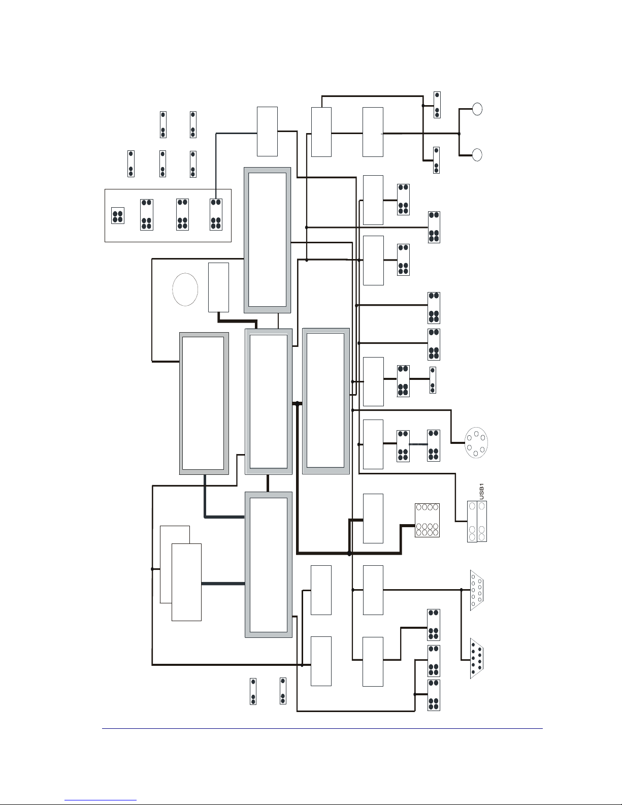
Block Diagram
The block diagram shows all of the functional units of the E1 - CPU. The physical plug-in connections to the system and external peripherals are shown at the
bottom of the diagram. Only the most important internal connectors are part of
the block diagram (see next page).
4
P en tium 4 - M P ro ce s s o r < = 2.4 G H zorM o b ile C e le ro n P ro c es s or < = 2 .4 G H z
G rap h ics & M em o ry
C o n tr o ller H u b
G M C H
82 8 4 5 G V
I/O Co n trolle r H u b
IC H 4
82 8 0 1 D B
S u pe r I/O
P C 8 7 3 66
F irm w a re H u b
F W H
82 8 0 2
S y nth e sizer
AudioCodec`97CS4299
P C I S e ria l P o r t C n
trl
.
3V
Lith iu m
StereoAmplifierTEA2025BFloppyInterfaceEID
EInterface
P C I O n b o ard
In terfa c e
S eria l
In terface
R S 2 3 2
P a ralle l
Interfa ce
CashdrawerInterface
Voltage
R e g ulator
2x 2 2 po l.
2x 8 po l. 2x1 3 po l.
1x 4 p o l.
F latpa ne l
In terfa c e
C R T
In terface
P a ralle l
Interfa ce
tatu s D is play
RisercardInterface2
x38po
l.2
x62po
l.2x22pol.SecondaryPrimary2x22pol.3.5mmMo
no3.5mmStereoMicSpeaker1x4pol.1x3pol.CD-AudioLineIn
Lo u d s pe ak e r
1x4 po l.
2x 4 po l.
U S B
9p ol.
C O M 1
2x9pol.PSU2
S M B u s
P C I B u s
S y stem Bu s
M em ory B u s
D D R -R a m
2 D IM M s
12 8 M B u p to 2 G B
USB2IT8874FUSBplusInterfaceCOM*Interface2x22pol.2x13pol.2x9pol.1x3pol
.1x4pol.1x3pol.WOLNPONFAN
1
1x 80 p o l.
2x9pol.2x10pol.
2x5pol.PSU1PUSBPSU2
P
o
w
erSuppl
y
C o n ne c tors
1x3pol.FAN21x4pol.Mouse
2x 2p o l.
P S AT X
USB5,6InterfaceUSB5,62x8pol.FloppyInterface2x17po
l.GameportInterfaceGameport2x5pol
.9pol.
C O M 2
*6pol.MiniDINKeyboard/MouseLAN10/10026pol
.
F
o
il2x22pol
.
5
Technical Data
Supported Systems
BEETLE /M II
Architecture
PC-AT compatible and POS –specific
functional units
Operating Modes
Normal Mode, Power Save Mode
Power Management
ACPI 1.0, APM 1.2
Operating Systems
XP embedded, WIN XP, LINUX
Microprocessor
INTEL PentiumR4-M (478 Pin
uFCPGA package, 0.13 u technology)
or
INTEL Mobile CeleronR(478 Pin
uFCPGA package, 0.13 u technology)
Frequencies from 1.7GHZ up to 2.4GHz
8 KB L1 data cache, 12 KB L1 program
cache, up to 512KB L2 cache (dependent on processor)
Chipset
INTEL Chipset 845GV (contains 2 ICs):
Graphic and Memory
Controller Hub (GMCH)
Memory Cntrl. Supports DDR SDRAM
with 266 MHz System memory bus,
Video memory is part of main memory,
Graphic supports 2D and 3D and video
streams
Video memory with INTEL Extreme
Graphics Driver max. 64MB (Dynamic
Video Memory Technology)
6
Max. Resolution CRT
2048 x 1536 x 32 Bit color @ 60 Hz
Max. Resolution TFT
1600 x 1200 24 Bit color
I/O Controller Hub 4 (ICH4)
LAN 10/100 Cntrl., IDE-Cntrl. w/ UDMA,
USB Cntrl. UHCI and EHCI, AC97 Link
for Audio and telephony CODEC, Interrupt-Cntrl., DMA-Cntrl., LPC-Interface,
RTC, SMBus-Host interface
Super I/O
NS87366
Floppy Cntrl., Parallel Port, 2 Serial
Ports, Keybd. Interface, PS/2 Mouse
Interface, HW- Monitor
Sound controller
CS4299 Audio Codec controller with the
following AC`97 functions: 20 Bit Stereo
DAC and 18 Bit Stereo ADC Analog
Line-Level Input (CD)
Mono Mic Input (MIC)
Stereo Line-Level Output
Sound connection
Mono Microphone Input,
Stereo Speaker
Output (2 x 1,25 W@ 8 Ohm)
Main Memory
128 MB up to 2GB, 2 DIMM - sockets
(184 pin), 2.5 V
DDR SDRAM technology, unbuffered
nonECC, DDR266 - Standard DIMM
Height up to 35 mm
PCI Interface
PCI-Bus (32 bit interface, 33MHz)
BIOS
Firmware Hub 82802 (FWH):
512KB Flash Memory, Phoenix BIOS,
PnP, PCI Rev.1.0A, DMI -support
Battery
3 V Lithium for RTC and SIO
Type: CR1/3 N , 160 mAh
System Bus Frequency
400 MHz
RAM Bus Frequency
266 MHz

7
PCI Bus Frequency
33 MHz
Wake On feature
Wake On LAN (w/ connector for Standard- LAN- adapter), Wake On MODEM
support, Wake on Time
Keyboard connection
PC-AT compatible
PS/2-Mouse connection
via Y-cable together with keyboard
optional internal connection
Serial interfaces
COM1, COM2*
COM3*, COM4* - adapter
optional and alternative to
(USB2plus, USB3plus, USB4plus)adapter
Parallel interface
IEEE1284 compatible (ECP, EPP,
PS/2-compatible)
Loudspeaker
AT-compatible,
volume control defined by BIOS Setup
in 3 steps: high- , medium- , low
volume
Floppy disk connection
Standard interface CMOS, NEC 765
compatible, foil connector and 2.54 mm
connector
Hard disk connection
Local Bus IDE interface,
Primary/Secondary for 4 drives,
PIO Mode 0 - Mode 4,
ULTRA DMA Mode 0 –Mode 2,
2mm connector for primary and
secondary each
USB connection
Version 1.1, 2.0
USB1, 2: Standard 2 port connector,
series A
USB(2),3,4: Standard 1 port connector
+ power (i.e. BERG 74239-X00)
(USB2plus, USB3plus, USB4plus)adapter with +5V system voltage optional and alternative to COM3*,
COM4*- adapter (if USB plus -adapter is
used, USB2 is not available)
USB5,6: 2 x 4 pin header, 2.54 mm
8
Cash drawer connection
up to 2 cash drawers can be connected,
connection via RJ12 connector inside
Power supply (only for one cash
drawer)
Gameport
2 x 8 pin header, 2.54 mm
PCI Plug-in card interface
32 bit interface, 33 MHz
Status display connection
support for LEDs: Power On and HD
activity
Current Consumption
Pentium 4-M/2.2 GHz
512 MB Ram
+ 3,3 V ~ 3,5 A
+ 5 V ~ 0,7 A
+ 12 V ~ 3 A
Max. Current
(for keyboard)
+5V. 500 mA
Max. Current per port
(for COM2*,3*,4*)
+12V: 600 mA
Max. Current in total
(for COM2*,3*,4*)
+12V: 900 mA
Max. Current per port
(for COM2*,3*,4*)
+5V: 300 mA
Max. Current in total
(for COM2*,3*,4*)
+5V: 500 mA
Max. Current per port
Standard USB1,USB2
+5V: 500 mA
Max. Current in total
Standard USB1,USB2
+5V: 1,0 A
Max. Current per port
Powered USB
(for USB2plus, USB3plus,
USB4plus)
(for USB2plus, USB3plus,
USB4plus, 12V version)
(USB4plus, 24V version)
+5V: 500 mA
+12V: 1,5 A
+24V: 3,0 A
9
Max. Current in total
Powered USB
(for USB2 plus, USB3 plus,
USB4 plus)
(for USB2 plus, USB3 plus,
USB4 plus, 12V version)
(for USB2 plus, USB3 plus,
USB4 plus, 24V version)
+5V: 1,5 A
+12V: 2,0 A
+24V: 3,0 A
Fuses (Polyswitches)
+5V
COM2*, COM3*, COM4*,
USB1, USB2, Keyboard, Mouse
Powered USB (Fuse on adapter)
+12V
COM2*
COM3*, COM4* (Fuse on adapter)
Powered USB (Fuse on adapter)
+24V:
Powered USB (Fuse on adapter)
Board Dimensions
255 mm x 220 mm
10
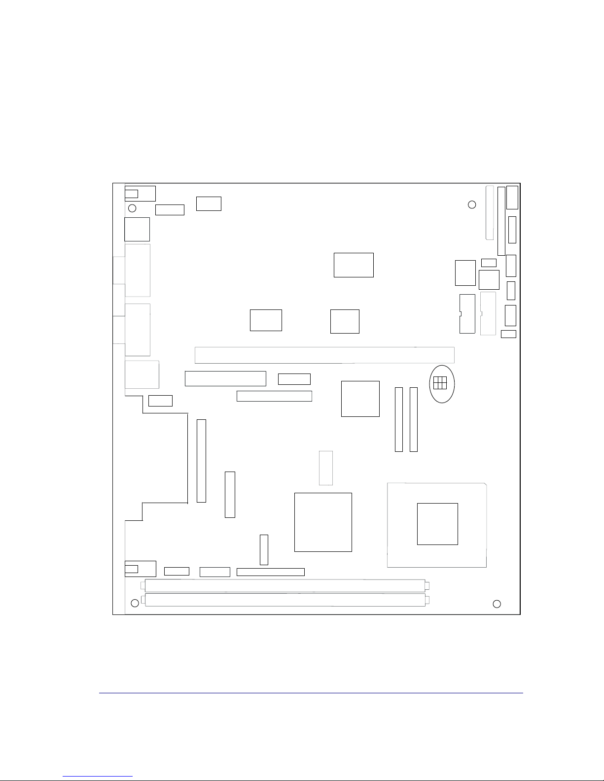
Mechanical Arrangement
The CPU comprises the printed circuit board with connectors for all external
peripheral connections and for installing the optional plug-in cards.
FD/F
POW1
POW2
+Battery-
FD/2.54mm
Gameport
POW3
Fan2
LSP
LED
PWON
Fan1
MS/INT
MIC
KYB/
MSE
COM1
COM2*
USB1/
USB2
SPK
OUT
CD-AUDIO
LINE IN
VGA/TFT
PCI
LPT
PCI-ONBOARD
VGA/CRT
GMCH
DIMM0
DIMM1
SuperI/O
IT8712F
IDE1
PENTIUM 4
-
M
ICH4
BIOS
FWH
SuperI/O
PC87366
CS4299
USB2P/3P/4P
LAN
PUSB
PT
1
IT 8874F
COM3*/4*-(PnP)
USB5,6
AC97
IDE2
or
Mobile Celeron
11
On-board Components
Processor
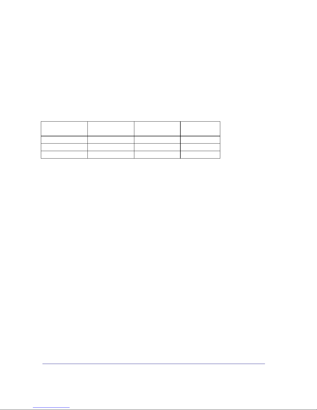
The E1- CPU supports Pentium 4-M processors as well as Celeron processors
in FC-PGA package. The released types are:
Processor
type
Processor
speed
System Bus
frequency
Cache size
Mobile Celeron 2.4 GHz 400 MHz 256 KB
Pentium 4-M 1.7 GHz 400 MHz 512 KB
Pentium 4-M 2.2 GHz 400 MHz 512 KB
Mobile INTEL Pentium 4-M Microprocessor
The Processor utilizes a 478-pin, Micro Flip-Chip Pin Grid Array (Micro-
FCPGA) and runs with 400MHz system bus. The program cache is a
12KB L1 cache and the advanced transfer cache is a 512KB L2 cache.
The processor supports Enhanced Intel SpeedStep technology.
The microprocessor is binary compatible with other members of the x86
family.
The INTELRPENTIUMR4 –M uses AGTL+ signaling technology. This
low power technology has larger noise margins and reduced ringing than
GTL.
Mobile INTEL Celeron Microprocessor
The Processor uses a 478-pin, Micro Flip-Chip Pin Grid Array (Micro-
FCPGA) and runs with 400MHz system bus. The execution trace cache is
a 12KB L1 cache and the advanced transfer cache is a 256KB L2 cache.
The microprocessor is binary compatible with other members of the x86
family.
The INTELRCELERONRuses AGTL+ signaling technology. This low
power technology has larger noise margins and reduced ringing than
GTL.

12
I/O Controller Hub
This Hub provides extensive I/O support. Functions and capabilities include:
PCI (33 MHz) support
Enhanced DMA controller, Interrupt controller and Timer functions
Integrated IDE controller supports Ultra ATA 100/66/33
USB host interface (3 UHCI Controller with 2 ports each Vers. 1.1
and 1 EHCI Controller with 6 ports Vers. 2.0)
Integrated LAN controller 10/100 Mbit/sec Ethernet
System Management Bus (SMB)
AC97 Vers. 2.3 support for audio and modem
Low Pin Count (LPC) interface
Firmware Hub (FWH) interface support
Super I/O-Controller
This is a Low Pin Count Interface-based highly integrated Super I/O and provides the following functions:
Two 16C550 UARTs
IEEE1284 Parallel Port
Floppy Disk Controller
Keyboard and PS/2 Mouse Controller
Game Port
Enhanced Hardware Monitor
Fan Speed Controller
40 General Purpose I/O pins
The Super I/O Controller is housed in a 128 pin QFP package.
13
Main Memory
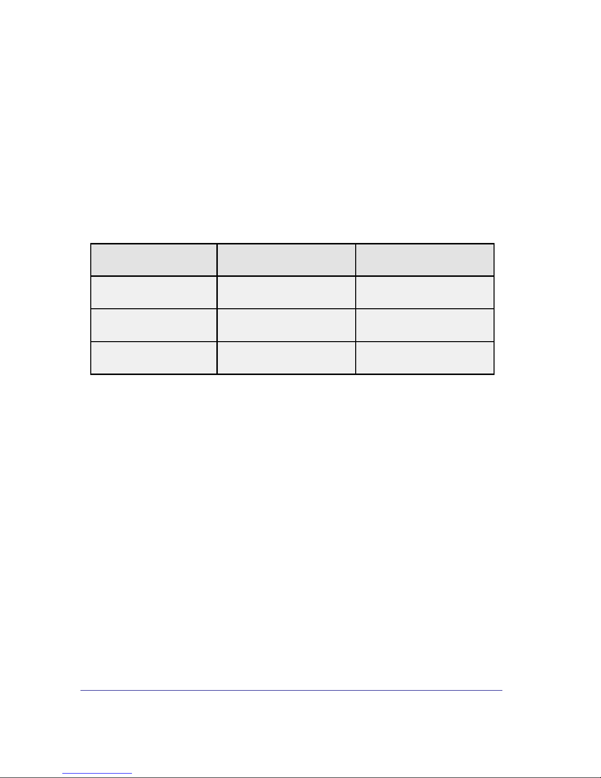
On the E1- CPU two DIMM (184 Pin) sockets are provided for connecting DDR
modules in unbuffered SDRAM technology from 256 MB ( 1 x 256 MB) up to 2
GByte (2 x 1GB) DDR DIMMs with different sizes can be used.
One or both DDR DIMMs may be assembled. The DDR DIMMs are unbuffered
2.5V memory modules.
The BIOS automatically detects via SPD memory type, size and speed.
Main Memory
Socket 1 Socket 2 Total capacity
32MBx64 (32MBx64) 256 MB (512 MB)
64MBx64 (64MBx64) 512 MB (1 GB)
Any combinations of these four DIMMs are allowed.

14
Graphic System
Graphics and Memory Controller HUB 82845GV (GMCH)
The GMCH integrates a system memory DDR SDRAM controller that supports
64MB up to 2GB memory (266MHz). It contains also a graphic controller for
enhanced integrated 2D and 3D graphics performance.
The GMCH drives via a CRT adapter a standard CRT monitor up to a resolution
of 2048x1536 pixels with 32-bit at 60 Hz.
For connecting TFT LCDs the GMCH provides a Digital Video Out interface to
implement a resolution up to 1600 x 1200 pixels with 24-bit. The DVO interface
is driving the LCD-TFT adapter (Panellink Bridge) and has low voltage highspeed signaling to allow operating at higher frequencies.
The GMCH has a core voltage of 1.5 V, the system memory operates with
2.5 V.
The GMCH is housed in a 760 pin BGA package.
15
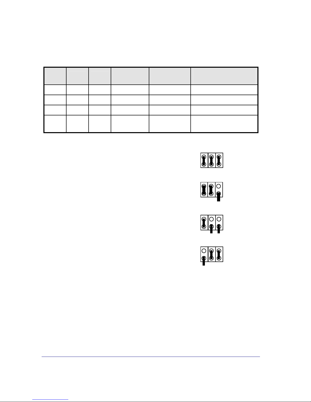
Jumper Settings
PT 3
PT 2 PT 1
VIDEO
Mode
DISPLAY
Size
Display Type /
Clock Freq.
closed closed closed
SVGA
TFT 12" BA 72A (30 MHz)
closed closed open
XGA
TFT 15" BA 73A (65 MHz)
closed open open
SVGA
TFT 12" BA 72A–1 (38 MHz)
open closed closed
VGA
TFT 10"
640 x 480
(PB Application)
12” Monitor BA72A PT:
1
15” Monitor BA73A PT:
1
12” Monitor BA72A-1 PT:
1
10” Monitor 640 x 480 (special application) PT:
1
When using a «Plug and Display» TFT screen (e.g. BA72A-2; BA73A-2 or
SNIkey 12A-2) a special jumper setting is not necessary.

16
PCI Serial Port Controller IT8874F
The on-board IT8874F provides a simple solution to build a serial port on PCI
bus with PnP features. The controller integrates two serial ports based on
16C550 UART function.
The IT8874F is housed in a 128 pin PQFP package.
Audio System
The CS4299 is a Codec with AC´97 features. It is implemented as 20 bit stereo
DAC and 18 bit stereo ADC with sample rate conversion. The E1- CPU uses
one microphone mono input, a line stereo input and the line stereo output which
will drive the stereo amplifier TEA2025B.
The CS4299 is housed in a 48 pin LQFP package.
Stereo Amplifier TEA2025B
The TEA2025B is a stereo audio power amplifier capable of delivering typically
1,25 Watt per channel of continous average power to an 8 Ohm load with 0.1%
(THD) using a 12 V power supply.
The TEA2025B is housed in a 16 pin DIL package.
Clock Generator RTM660-109R
The REALTEK Clock Generator RTM660-109R is designed for the INTEL chipset 845GV and provides all clocks for the chipset, microprocessor, DDR DIMMs,
PCI interface, USB interface and Super I/O.
The RTM660-109R provides an I2C 2 wire interface to program the internal
registers. For EMI reduction the synthesizer provides programmable spread
spectrum. The RTM660-109R is housed in 56 pin SSOP package.

17
Hardware Monitoring
The PC87366 contains an enhanced Hardware Monitor which will be used for
sensing/ controlling the following signals:
Temperature of the processor
Core voltage of the processor
3,3V system voltage
2,5V system voltage for power management
1,5V core voltage
5V system voltage
Battery voltage
12V system voltage
-12V system voltage
Fan tachometer signal of processor fan
Fan tachometer signal of system fan
Fan tachometer signal of PSU fan
Fan Control (processor- and system- fan)
Fan Control (PSU fan)
Floppy Interface
For connecting Floppy drives there are two different connectors on the CPU
available. These are a 2.54mm standard header for 1” drives and a foil cable
connector for ½”drives.
Standard 1.44MB and 720KB Floppy Discs are supported.
32 Bit PCI Onboard Plug-In Modul Interface
The Onboard 32 bit PCI bus interface is provided to assemble new PCI bus
based Plug-In-Modules.
The PCI bus interface contains all signals, which are necessary for a doublesided (two clock signals) PCI Master module. Furthermore the WOL interface is
provided, i.e. the Standby Voltage and the Wake On signal are available.

18
Serial Interface COM1, COM2*
COM1 is the standard serial interface controlled by the Super I/O PC87366.
On the 9 pin DSUB connector(male) are all signals available incl. the modem
signals RI and DCD.
The I/O assignments of the serial port COM2* deviate from the standard in the
way it is equipped with system voltages of +5V and +12V instead of the signals
RI (M3) and DCD (M5).
The channel is connected via 9-pin D-sub (female) socket because of the additional system voltages.
Serial Interface COM3*, COM4*
These serial interfaces are controlled on the mainboard by the SuperI/O IT8874
(PnP). The interface signals and the voltages +5V and +12V are routed to a 2 x
13 pin header (2 mm). This header serves as serial interface connector for the
COM3*,COM4* interface adapter.
Keyboard / PS/2 Mouse Interface
The keyboard controller is part of the SuperI/O. The keyboard interface - as well
as the PS/2 –mouse interface - is available on the Mini DIN connector. For
usage both of them a Y- adapter-cable(introduced) is necessary.
USB Interface
The USB interface supplied by the ICH4 contains 3 host controller for 6 downstream ports providing both data rates, 12 Mb/sec for full speed USB peripherals
and 1.5 Mb/sec for low speed USB peripherals. Software protocol relates to
UHCI Design guide (USB 1.1). Additionally one EHCI host controller is implemented to support all 6 ports with high speed 480Mb/sec (USB 2.0).
USB ports 1 and 2 are available on the mainboard.
The USB connector is type Stack A.
USB ports 3 and 4 are available if one of the PowerUSB modules (12V or 24V)
is used (USB3plus,USB4plus). Instead of USB2 onboard USB2plus on the
Power USB module is available.

19
On the PowerUSB modules are connectors (i.e. type BERG 74239-x00) assembled.
USB ports 5 and 6 are on a 2.54 mm header onboard available. A special cable
has to be used for connecting to the rear- or the frontside of the BEETLE system.
Parallel Interface
The standard interface LPT1 may be used for peripherals with parallel interface.
There are several modes supported (PS/2 compatible, EPP and ECP). The
connector on the CPU is a 2 x 13-pin header.
Hard-Disk Interface (IDE)
The CPU features a UDMA IDE interface for connecting up to 4 ATA compatible drives. The I/O addresses conform to the AT standard. The connectors on
the CPU are 2 x 22-pin header (2-mm arrangement) for primary and secondary.
All parameters of the drives are read by the BIOS automatically and stored in
the BIOS setup parameter set.
The E1- CPU supports IDE drives up to PIO-Mode 4 and UltraDMA Mode 2.
Cash Drawer Interface
The logic for controlling the cash drawers is placed on the E1- CPU. The I/O
assignment is compatible to other CPU´s in BEETLE systems.
Input031x/ bit6 LAZU1N=0 Cash drawer 1 closed or not present
(x = 0 –7) LAZU1N=1 Cash drawer 1 open
Input031x/ bit7 LAZU2N=0 Cash drawer 2 closed or not present
(x = 0 –7) LAZU2N=1 Cash drawer 2 open
The output bit KLA1,2 unlocks the cash drawers.
Output 031x/ bit6 KLA1=0 No activity
(x = 0 –7) KLA1=1 Unlock cash drawer 1
Output 031x/ bit7 KLA2=0 No activity
(x = 0 –7) KLA2=1 Unlock cash drawer 2

20
Bit 6 and Bit 7 never may be set both. Only one of them has to be activated at
the same time. A driver has to be installed to prevent opening both cash drawers. The time delay between opening drawer 1 and drawer 2 has to be about 0.5
–1 second.
The length of the pulse for opening the cashdrawer has to be nominal
130msec.There must be a time interval of 6 seconds between two outputs
(charging time of capacitor in the cash-drawer electronic circuitry).
Status Display Interface
To display system activities there are two interface signals available.
LED 1 green : Power On
LED 2 yellow: Hard Disk activity / Memory Card activity
Fans
Three fans are supported by the CPU, i.e. three tacho lines are monitored by
Hardware and may be reported via BIOS SETUP.
For controlling the fan speed, two Control lines are implemented. The PSU fan
is controlled by one line, CPU- and system- fan are controlled via a common
line.

21
Changing the CPU Battery
The BEETLE POS systems are equipped with a lithium battery on the CPU
board to ensure data retention, the time and the setup parameters. The battery
should be changed approximately every five years.
When inserting the new battery, make sure the polarity is correct. This is
visibly marked in the socket. Incorrect replacement of the battery may lead
to the danger of explosion.
The battery is located in a socket in the CPU (see page 10). To gain access to
the battery, proceed as described in the according chapters of your BEETLE
User Manual.
The lithium battery must be replaced only by identical batteries or types
recommended by Wincor Nixdorf International.
You can return the used batteries to your Wincor Nixdorf International sales
outlet.
Batteries containing harmful substances are marked accordingly. The
chemical denotations are as follows: CD = Cadmium; Pb = Lead,
Li = Lithium.
This symbol on a battery tells you that batteries containing
harmful substances must not be disposed of as household
waste. Follow the country specific laws and regulations. Within
the European Union you are legally bound to return these batteries to the service organisation where you purchased the
new battery.
The setup parameters must be reset each time the battery is changed.

22
Plugin Modules
CRT Adapter
A new CRT adapter is available for the E1 CPU. It is downwards compatible to
the D2 Star-CPU.
COM3*,4* Adapter
A new COM3*,4* module with PnP-features is available for the E1- CPU.
It may be assembled only alternatively to a USBplus adapter.
The voltages +5V and +12V are protected via Polyswitches.
USBplus Adapter (USB 2.0; 2 versions)
The new USBplus adapter (USB 2.0) is available in two versions :
12V version with 3 USBplus ports with 12V
24V version with 2 USBplus ports with 12V and 1 USBplus port with 24V
The voltages +12V and +24V are protected via polyswitches.
LCD-TFT Adapter
There is a new LCD-TFT adapter (PanelLink Bridge) to connect the display
family w/o DDC (BA72A, BA73A) as well as the display family with DDC
(BA72A-2, BA73A-2).
 Loading...