

Wincor Nixdorf D425-CPU User Manual

POS
Motherboard
D425-CPU
User Manual

We
would like to know your opinion on this publication.
Please send us a copy of this page if you have any constructive criticism.
We would like to thank you in advance for your comments.
With kind regards,
Wincor Nixdorf International GmbH
Documentation RD HWD01
Rohrdamm 7
D-13629 Berlin
E-Mail: retail.documentation@wincor-nixdorf.com
Ord
er No.: 01750220414A (POS Motherboard with D425-CPU)
Your opinion:

POS
Motherboard
D425-CPU
User Manual
Edition October 2011

All
brand and product names mentioned in this document are trademarks of their
respective owners.
Copyright © Wincor Nixdorf International GmbH, 2011
The reproduction, transmission or use of this document or its contents is not permitted without
express authority.
Offenders will be liable for damages. All rights, including rights created by patent grant or
registration of a utility model or design, are reserved.
Delivery subject to availability; technical modifications possible.
Refer to protection notice ISO 16016

Con
tents
Introduction ................................................................................................. 1
Basic Features of D425 Motherboard........................................................2
Processors .................................................................................................... 2
Features........................................................................................................2
Motherboard Specification......................................................................... 3
Blockdiagram of D425 Motherboard.............................................................. 3
Motherboard Mechanical Arrangement ......................................................... 4
Motherboard PCB Dimension........................................................................ 4
External I/O Connector..................................................................................5
Internal I/O Connector................................................................................... 5
Jumper Setting.............................................................................................. 6
Power Consumption of D425 Motherboard................................................... 6
Maximum Current Rating for External Peripherals ........................................ 7
Supported Power Modes (Sx)....................................................................... 7
Thermal Management ................................................................................... 7
CPU Support................................................................................................. 8
Memory Support............................................................................................ 8
Graphics Subsystem.....................................................................................8
System Clock Generator...............................................................................9
Fast Ethernet LAN Interface.......................................................................... 9
Super I/O Controller ...................................................................................... 9
SATA II Interface......................................................................................... 10
IDE Interface...............................................................................................10
CPU Fan and System Fan........................................................................... 10
Audio........................................................................................................... 11
USB Interface.............................................................................................. 11
Serial Interfaces COM1-5............................................................................ 12
Parallel Port................................................................................................. 12
PS/2 Keyboard and Mouse Interface........................................................... 12
Front Panel Interface................................................................................... 12
Cash Drawer Interface ................................................................................ 13
Cash Drawer Interface I/O 310h............................................................. 13
Intrusion Detect Interface............................................................................ 13
TPM.............................................................................................................13
System Beeper............................................................................................13
Connector and Pin Assignments............................................................. 14
External Connectors.................................................................................... 14
PS/2 Keyboard and Mouse Connector....................................................14

Fast Eth
ernet LAN Connector.................................................................14
USB Connectors .....................................................................................15
COM1 Connector....................................................................................15
COM2*-5* Connectors ............................................................................16
Type: DSUB-9 pin...................................................................................16
VGA Connector.......................................................................................17
Audio Connector.....................................................................................17
LPT Connector........................................................................................18
Connectors and Headers for internal Connection........................................ 19
SATA.......................................................................................................19
USB Header............................................................................................19
Front Panel Interface Connector.............................................................20
Cash Drawer Interface Connector...........................................................20
Fan Connector (with PWM FAN Speed Control).....................................21
Intrusion Interface ...................................................................................21
ATX Power..............................................................................................21
PATA IDE................................................................................................22
PCI..........................................................................................................23
Technical Data...........................................................................................27
Changing the Battery ................................................................................29
Addendum..................................................................................................30
Sleep States............................................................................................30
LED LAN (RJ45).....................................................................................30
BIOS Setup.................................................................................................31
Standard BIOS Version...............................................................................31
BIOS Menu Bar.......................................................................................32
Legend Screen........................................................................................32
General Help...........................................................................................33
Scroll Bar ................................................................................................33
Sub-Menu ...............................................................................................33
Info Screen..................................................................................................34
Product Name.........................................................................................34
BIOS Version..........................................................................................35
MAC Address..........................................................................................35
UUID Info ................................................................................................35
System, Main board, Power Supply........................................................35
Main Menu...................................................................................................35
System Time [XX: XX: XX]......................................................................35
System Date [XX/XX/XXXX] ...................................................................36
Advanced Menu...........................................................................................36
Sub Menu Hardware Monitoring..........................................................36
Sub Menu SuperIO Information...........................................................37
Sub Menu CPU Configuration.............................................................38
Sub Menu IDE Configuration...............................................................39
Sub Menu USB Configuration.............................................................41
Sub Menu > Hardware Control................................................................42

Sub
Menu North Bridge Configuration................................................ 45
Boot Menu................................................................................................... 45
Boot Settings Configuration.................................................................... 46
Bootup Num-Lock [On] ........................................................................... 46
PS/2 Mouse Support [Auto] .................................................................... 46
Security Menu ............................................................................................. 47
Change Supervisor Password ................................................................ 47
Change User Password.......................................................................... 47
Intrusion Detection [Disabled]................................................................. 47
Exit Menu.................................................................................................... 48
Save Changes and Exit .......................................................................... 48
Discard Changes and Exit ...................................................................... 48
Discard Changes .................................................................................... 48
Load Defaults..........................................................................................49
Test Points Codes....................................................................................... 49
Bootblock Initialization Code Checkpoints................................................... 49
POST Code Checkpoints............................................................................ 50
Boot Block Beep Codes .............................................................................. 52
POST BIOS Beep Codes............................................................................ 52
Troubleshooting POST BIOS Beep Codes.................................................. 52
Abbreviations ............................................................................................ 53
D42
5-CPU-Desktop 1
Introduction
This User Manual describes the features of a Motherboard based on the
INTEL D425 processor and ICH8M chipset in mITX form factor.
This new D425 Motherboard is designed for Wincor Nixdorf’s BEETLE /i8A,
BEETLE / SII+ family and BEETLE /mini.
D425 Board
No
Amplifier onboard
Cash dr
awer support onboard
Fast E
thernet 100Mbit
Tar
get system: B/SII+, B/i8A-3, B/mini

2 D42
5-CPU-Desktop
Basic Features of D425 Motherboard
Processors
The features of the motherboard based on the INTEL D425 processor and
ICH8M chipset in mITX form factor.
Features
Intel ATOM processor D425 (single core), 1.8GHz
Integrated Intel 3rd Gen Graphics Core
1 VGA
HDD SATA II interfa ce ( 2 ports)
HDD PATA interface 4 4 pin for compact flash module
Supports chassis fan with automatic PWM speed control
Fast Ethernet 100Mbit LAN onboard
One DDR3 SDRAM (SO-DIMM) socket, up to 2GB / 800MHz supported
One PCI slot supporting SMBUS
5 COM ports (4 ports have the option to be powered COM)
8 USB ports
1 Cash drawer Altera CPLD onboard
Intel HD audio controller with microphone, line in and line out connectors
NVRAM module support via PCI riser card
OS support includes Windows 7
Long term availability for 5 years (Intel embedded roadmap)
D42
5-CPU-Desktop 3
Motherboard Specification
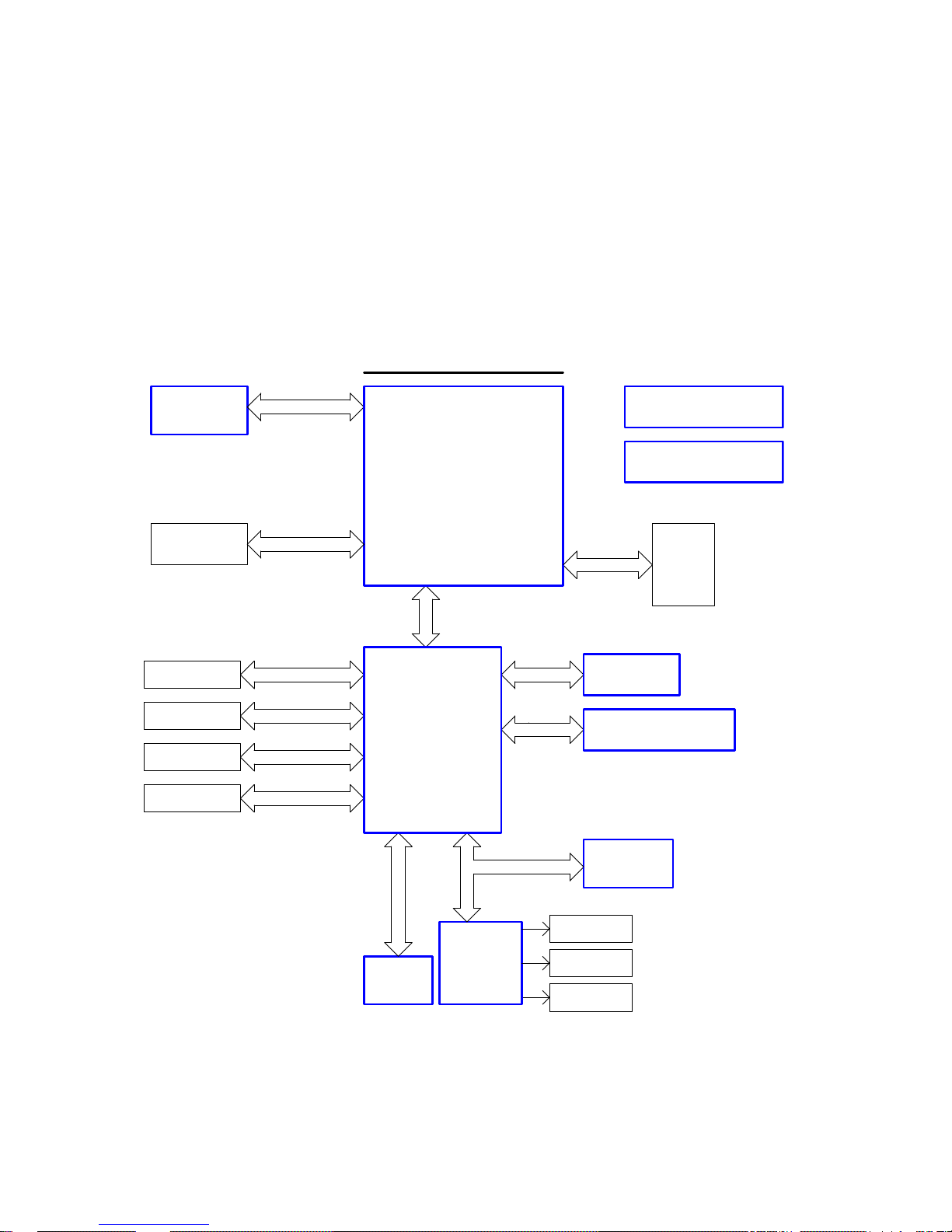
Blockdiagram of D425 Motherboard
REALTEK RTL8105E
LPT
Block Diagram
System Power
RT8207 RT9018 RT9199
SPI
Cash Drawer
PCIe x1
44pin IDE
LAN
USB Port 1~8
HD Audio Codec
ALC262
SATA2
Module
SATA-II 1,2
1 DDR III
PATA IDE
Intel ATOM Processor
DDRIII
VRD 11
SODIMM
DDR3 800
1-Phase PWM
Analog
Video (VGA)
RGB
PCI (33MHz, 32bit)
PCI Slot
ITE
LPC SIO
ICH8M
IT 8
783F
SPI
LPC
USB2.0
DMI
4 COM*
ISL6 314
HD Audio Link
1 COM
5M40ZE64
Flash ROM
PS/2
KEYBOARD
Clock
REALTEK RTM875T-531
D425
4 D42
5-CPU-Desktop
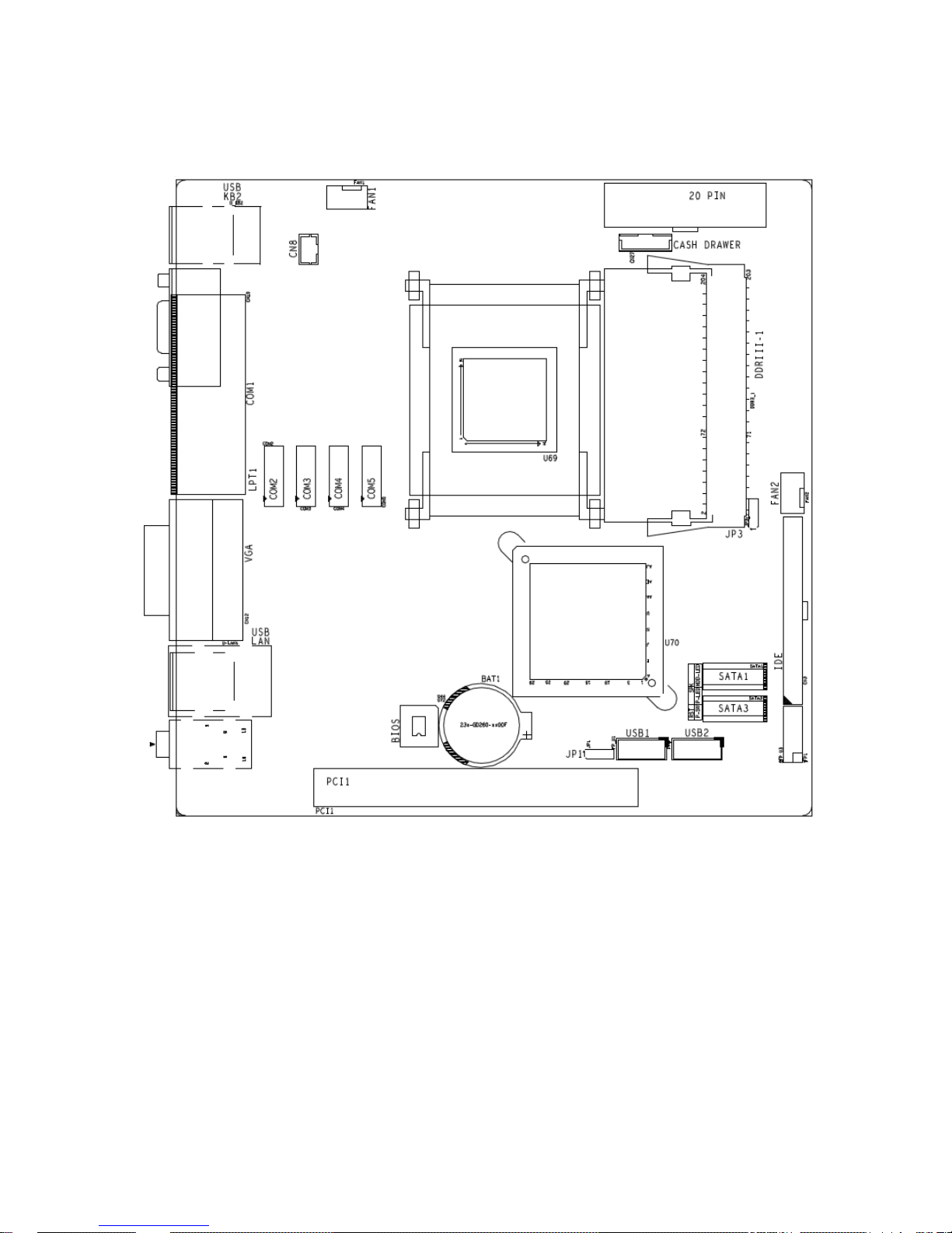
Motherboard Mechanical Arrangement
Motherboard PCB Dimension
D425 motherboard (including I/O shield) follows mITX standard and therefore PCB mechanical dimension is 170mm x 170mm.

D42
5-CPU-Desktop 5
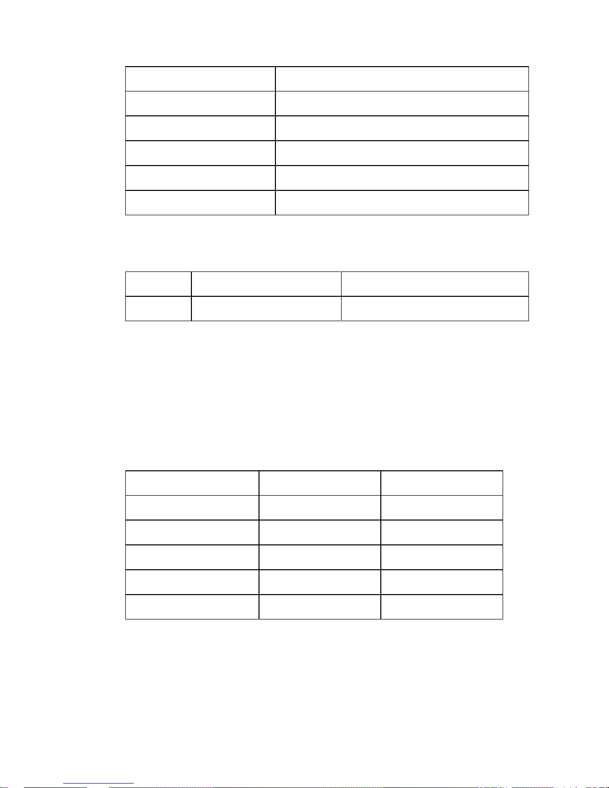
External I/O Connector
External I/O connectors are arranged as illustrated here:
Interface Connector-Type
COM
1 9 pin D-sub male
LPT 25
pin D-sub female
Key
board, Mouse, USB 6 pin Mini Din + stacked dual USB series A
LAN
, USB RJ45 Ethernet + stacked dual USB series A
VGA 15
pin HDD-sub female
AUD
IO Line Out 3,5 mm female
AUD
IO Line In 3,5 mm female
AUD
IO Microphone 3,5 mm female
Int
ernal I/O Connector
Interface Connector-Type
DDR3
SO-DIMM 1pcs 204 pin micro edge connector
PATA
IDE 1pcs 44 pin header, 2mm (425 only)
Har
d disk (SATA) 2pcs 7 pin Standard SATA headers
3.3V
, 5V, 12V Supply ATX 20 pin power connector
USB
port 4-8 2pcs 2x5 pin headers, 2.54 mm
COM1
VGA
LAN
/USB
AUDIO
LPT
K/M/USB
6 D42
5-CPU-Desktop
COM* 2-5 4pcs 2x7 pin headers (2.0mm shrouded)
FAN 2pc
s 4 pin
PCI
1x standard PCI connector
Front
panel 1pcs 2x6 pin header, 2.54mm
Cha
ssis intrusion 1pcs 3 pins header (2.0mm shrouded)
Cas
h drawer 1pcs 6 pins header (2.0mm shrouded)
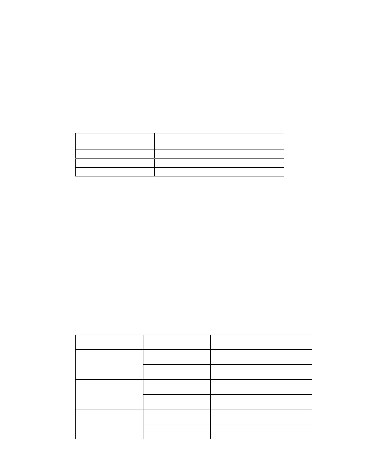
Jum
per Setting
Jumper Connector-Type Setting
JP1 CM
OS clear 1-2 default, 2-3 CMOS clear
Pow
er Consumption of D425 Motherboard
D425 motherboard is powered by 3.3V, 5V, 5Vstby, 12V and -12V from a
standard ATX power supply. The maximum current is specified as follows,
this does not include external connected peripherals.
Voltage I max P
3.3V 1A 3.3W
5V 1A 5W
5VSB 0.5A 2.5W
12V 1.5A 18
W
-12V 0.1A 1.2W

D42
5-CPU-Desktop 7
Maximum Current Rating for External Peripherals
Interface Voltage I max
Pow
ered COM (COM 2-5 total) 5V 1A
Pow
ered COM single port 5V 0.3A
Pow
ered COM (COM 2-5 total) 12V 1A
Pow
ered COM single port 12V 0.6A
USB
, single port 5V 0.5A
USB
, all ports total 5V 2A
PS/2 5V
0.5A
DVI
, VGA 5V 0.1A
Sup
ported Power Modes (Sx)
D425 Motherboard supports power states S0, S3, S4 and S5. Wake up
events from sleep states are supported from USB ports, COM1 ring
indicator, internal CMOS clock, PS2 Keyboard and Ethernet.
Power management supports ACPI 3.0 and APM1.2.
Thermal Management
D425 Motherboard supports 2 FAN connectors. The 1st FAN connector is
reserved for CPU fan. The 2nd FAN connector is connected to power supply
fan and detects it’s rotating speed.
Supported CPUs and it’s TDP and maximum junction temperature:
CPU TDP Idle power Max Tj
D42
5 10W 4W typ. 100°C
ICH
8M 3W 2W
8 D42
5-CPU-Desktop
CPU Support
Due to the fact Atom CPU comes in a BGA package it is soldered to PCB
and can not be changed.
Processor Core Clock Speed Footprint Max TDP
D42
5 1 1.8GHz FCBGA559 10W
Mem
ory Support
The motherboard has one SO-DIMM socket supporting single channel,
unbuffered, no ECC DDR3 SDRAM. Memory size of 1GB and 2GB.
DIMM Capacity DRAM Device
Technology
DR
AM Organization Ranks
1GB 1G
B 64M X 16 2
2GB 2G
B 128M X 16 2
1GB 1G
B 128M X 8 1
2GB 2G
B 256M X 8 1
The
motherboard supports the following memory features:
667 / 800 MHz unbuffered SDRAM SO-DIMM
Non-ECC
1.5V voltage rating
BIOS automatically detects memory type, size, and speed
If higher frequency memory modules than 800MHz are used, the frequency
will be limited to 800MHz automatically.
Graphics Subsystem
Graphics support is via the internal graphics accelerator of the D425 processor to provide single display.
D42
5-CPU-Desktop 9
Main features of integrated GPU are:
Intel® Dynamic Video Memory Technology support 4.0, up to 384MB
Directx® 9 compliant Pixel Shader® v2.0
400 MHz render clock frequency
Intel® Clear Video Technology
MPEG2 Hardware Acceleration
ProcAmp
The analogue VGA port utilizes an integrated 350MHz RAMDAC capable of
driving a standard progressive scan monitor resolution up to 2048 x 1536 at
60Hz.
Signal Voltage level
R,G
,B 0.7VP-P @75OHM
HSY
NC, VSYNC 5.0V
DDC CHA
NNEL OPEN DRAIN, 5.0V TOLERANT
Sys
tem Clock Generator
The clock generator is conforming to CK505 specification and made by
Realtek RTM875T-531. As 2nd source ICS9LPRS511 is available.
Fast Ethernet LAN Interface
Fast Ethernet LAN interface is provided through PCI-e based Ethernet
Controller by Realtek RTL8105E.
Super I/O Controller
Super I/O controller IT8783 from ITE provides the following functions:
Five 16C550 UARTs
PS/2 keyboard and mouse controller
Two automatic fan speed controller
10 D42
5-CPU-Desktop
Two tachometer inputs
Hardware monitor
SATA II Interface
The ICH8M has three integrated SATA host controller that supports
independent DMA operation and data transfer rates up to 3.0Gb/s.
SATA Port ICH8M Usage on Motherboard
Port
#0 On-board connector
Port
#1 Not connected
Port
#2 On-board connector
IDE
Interface
D425 Motherboard provides a standard PATA IDE 44 pin interface intended
for CF interface.
CPU Fan and System Fan
D425 motherboard supports automatic fan speed control by pulse width
modulation (PWM, 4pin fan connector).
If a 3 pin fan is used (BEETLE /mini) there is no rpm control.
The 2nd CPU fan connector FAN2 is indented to sense power supply fan.
System FAN connector Used as
FAN
1 Not used
BEETL
E /SII+
FAN2 Power supply
FAN
1 Not used
BEETL
E /i8A
FAN2 Power supply
FAN
1 CPU fan
BEETL
E /mini
FAN2 Not used
D42
5-CPU-Desktop 11
Audio
An INTEL HD Audio Link is provided thru ICH8M. It is used with a Realtek
HD Audio Codec ALC662 providing a low cost solution. In case of EOL the
ALC262 is prepared for AVL use.
Supported interfaces are:
Line-out
Mic-in
Line-in
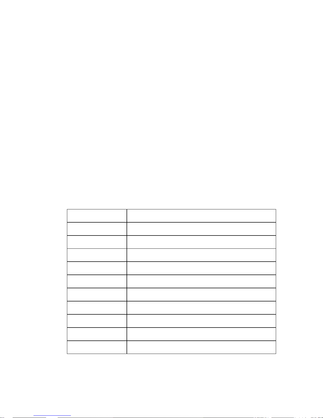
USB Interface
The ICH8M contains two EHCI compliant host controller that support USB
high speed signalling. High speed USB 2.0 allows data transfers up to
480Mb/s. The ICH8M also contains five UHCI controller that support USB full
speed and low speed signalling.
EHCI ICH8M Port Connection on Motherboard
0 USB
1 connector pin 1,3,5,7
1 USB
1 connector pin 2,4,6,8
2 USB
2 connector pin 1,3,5,7
3 USB
2 connector pin 2,4,6,8
4 PS/2 / U
SB connector upper port
5 PS/2 / U
SB connector lower port
6 LAN
/ USB connector lower port
7 LAN
/ USB connector upper port
8 Not
used
9 Not
used

12 D42
5-CPU-Desktop
Serial Interfaces COM1-5
D425 Motherboard provides five serial ports. COM1 is the standard serial
interface. On the DSUB-9 pin male connector all signals are available
including the modem signals RI and DCD.
The I/O assignments of the powered serial ports (COM2* to COM5*) deviate
from the standard as it is equipped with system voltage of +5V and +12V
instead of the signals RI and DCD. These serial ports are routed to 2x7 pin
headers (2.0mm shrouded) and to DSUB-9 pin female
connectors (via cables).
All serial ports comply with RS-232 signalling level voltage.
Parallel Port
D425 motherboard supports a parallel port according to IEEE1284.
PS/2 Keyboard and Mouse Interface
The keyboard and mouse controller is part of the Super I/O chip. The PS/2
interface is available on a Mini DIN connector.
Front Panel Interface
The motherboard provides a front panel interface, supporting the following
features:
Power ON/OFF button
Reset button
Status LED, showing Active (Green), Standby (Green, flashing),
Shutdown (Red), HDD Activity (Amber, flashing)
System beeper
 Loading...