

Wincor Nixdorf BEETLE /XL User Manual

BEETLE
BEETLE /XL
Modular POS System
User Guide


BEETLE /XL
User Guide
Edition June 2000

Pentium©is a registered trademark of the Intel Corporation
MS-DOS
©
is a registered trademark of the Microsoft Corporation
BEETLE is a registered trademark of the Wincor Nixdorf GmbH & Co. KG
Copyright © Wincor Nixdorf GmbH & Co. KG, 2000
The reproduction, transmissionoruseofthisdocument or its contents is not permitted
without express authority.
Offenders will be liable for damages.
All rights, including rights created by patent grant or registration of a utility model or design, are
reserved.
Delivery subject to availability; technical modifications possible.

Contents
Manufacturer’s Certification.....................................................................1
General Authorization..................................................................................1
FCC-Class A Declaration ............................................................................1
Tested Safety...............................................................................................2
Important notes............................................................................................2
Introduction..............................................................................................4
About this manual........................................................................................5
Cleaning the BEETLE /XL ...........................................................................6
Recycling the BEETLE /XL........................................................................7
Warranty....................................................................................................8
The individual POS system ......................................................................9
Overview......................................................................................................9
Before switching on the system.................................................................11
Unpacking and checking that everything is there................................11
Setting up the device ...........................................................................11
Cabling the BEETLE /XL......................................................................12
Securing the data cables .....................................................................13
Monting the cable cover.......................................................................14
Connecting to the mains power supply................................................15
Disconnecting cables...........................................................................16
Basic settings.......................................................................................16
Adjusting the loudspeaker ...................................................................17
Connecting peripherals..............................................................................18
Keyboard (KYBD)....................................................................................19
Cash drawer (CASHDRW) ..................................................................19
Scanners and scales (COM1 - COM4*) ..............................................20
Customer display (COM2* or COM4*).................................................21
Cashier display (COM3*) .....................................................................21
Monitor ................................................................................................22
Connecting standard PC peripherals (COM1).....................................22
Network................................................................................................23
Printer (LPT1 / 24V, 4A).......................................................................23

The BEETLE /XL components ............................................................... 25
Overview ...................................................................................................25
Storage concept ........................................................................................ 27
The BEETLE card .....................................................................................29
The card types ........................................................................................30
– SRAM cards.................................................................................. 30
– MASK ROM cards.........................................................................31
– OTPROM cards............................................................................. 31
– FLASH EPROM cards .................................................................. 31
Inserting the BEETLE card.................................................................. 31
Removing the BEETLE card ............................................................... 32
Write protection for BEETLE cards ..................................................... 32
Changing the battery when using SRAM BEETLE cards ................... 33
The floppy drive......................................................................................... 35
General................................................................................................ 35
Inserting a diskette .............................................................................. 36
Removing a diskette............................................................................ 36
The CPU.................................................................................................... 37
General................................................................................................ 37
Interfaces............................................................................................. 38
Loudspeaker........................................................................................ 38
Nonvolatile RAM (NV-RAM)................................................................ 38
Dyamic RAM........................................................................................39
– Connecting hard disks .................................................................. 39
– Free AT slots................................................................................. 40
– Additional slot on the CPU............................................................ 40
Possible expansions ................................................................................. 40
Mini-disk (MD) ..................................................................................... 40
PCMCIA...............................................................................................40
Streamer drive..................................................................................... 41
Magneto-optical drive (MO)................................................................. 41
Power pack................................................................................................ 42
Accumulator batteries ............................................................................... 43
Changing the accumulator batteries .................................................. 44
Security against power failure.............................................................47
Changing the lithium battery of the BEETLE /XL......................................48
LED indicators ..........................................................................................50
Configuration variations......................................................................... 51
Plug-in cards for the CPU ......................................................................... 51
ASYNC controller................................................................................ 51
VGA controller ..................................................................................... 51

LAN controller; VGA/LAN controller.....................................................51
Inserting plug-in cards..........................................................................52
AT plug-in cards.........................................................................................53
BEETLE in-house controller ................................................................53
PCMCIA controller...............................................................................53
SNIkey controller..................................................................................53
Inserting an AT plug-in card.................................................................54
Software....................................................................................................57
Operating system.......................................................................................57
Retail Device Interface...............................................................................57
Application programs.................................................................................58
Retail Presentation Manager.....................................................................58
Retail Transaction Manager ......................................................................58
High Frequency Table ...............................................................................58
Hash File Access Method..........................................................................58
Starting up the system............................................................................59
Startup behavior ........................................................................................59
Output of MS-DOS system error messages..............................................62
BIOS Setup ...............................................................................................63
Appendix...................................................................................................73
Technical data for the BEETLE /XL...........................................................73
ASYNC controller ....................................................................................75
VGA controller ...........................................................................................75
LAN controller ............................................................................................76
VGA/LAN controller ...................................................................................76
What to do if ..............................................................................................77
The configuration label ..............................................................................78
Power-on self-test (POST) ........................................................................79
MS-DOS critical errors ............................................................................80
POST error messages.........................................................................81
Phoenix BIOS POST and start messages...........................................83
– Additional messages .....................................................................86
Glossary.....................................................................................................87
Abbreviations.............................................................................................89

Manufacturer’s Certification
General Authorization
This device complies with the requirements of the EEC
directives 89/336/EEC “Electromagnetic Compatibility” and
73/23/EEC “Low Voltage Directive”. Therefore, you will
find the CE mark on the device or packaging.
FCC-Class A Declaration
This equipment has been tested and found to comply with the limits fora
Class A digital device, pursuant to part 15 of the FCC Rules.These limits are
designed to provide reasonable protection against harmful interference when
the equipment is operated in a commercial environment.
This equipment generates, uses, and can radiate radio frequency energy
and, if not installed and used in accordance with the instruction manual,
may cause harmful interference to radio communications.
Operation of this equipment in a residential area is likely to cause harmful
interference in which case the user will be required to correct the
interference at his own expense.
Le présent appareil numérique ne génèrepasdebruitsradioélectriques
dépassant les limites applicables aux appareils numériques de la “Classe
A” prescrites dans le Règlement sur le brouillage radioélectrique édicté
par le ministère des Communications du Canada.
GB - 1
Tested Safety
The BEETLE /XL has been provided with the symbol
for “Tested Safety”.
In addition, the BEETLE /XL has received the UL
symbol and the cUL symbol.
Important notes
Importantnotes
The modular POS system BEETLE /XL conforms to the current safety
standards for data processing equipment.
➜ If this device is taken from a cold environment into the operating
room, moisture condensation may form. The device must be
absolutely dry before being put into service; an acclimatization period
of at least two hours must therefore be observed.
➜ This device is equipped with a safety-tested power cable and may be
connected only to a grounded-contact power socket.
➜ When setting up the device, ensure that the power socket on the
device and the grounded-contact utility power socket are easily
accessible.
➜ To disconnect the device from the supply voltage completely, switch
off the device and disconnect the power plug.
➜ Ensure that no foreign objects (e.g. office clips) find their way into the
device, as this may lead to electric shocks or short-circuits.
➜ In order to ensure that the device is well ventilated and to prevent
overheating, do not obstruct the ventilation slots on your device.
➜ Never plug in or unplug data communication lines during
thunderstorms.
➜ Protect devices from vibrations, dust, moisture and heat.
Important notes
GB - 2

➜ The BEETLE /XL has two batteries.
These batteries must be replaced by authorized personnel only.
Incorrect replacement may lead to the danger of explosion.
➜ Always dispose of used parts in an environmentally safe manner.
➜ Thereisalithium battery on the system assembly. This battery must
be replaced by authorized personnel only. Incorrect replacement may
lead to the danger of explosion.
➜ The lithium battery must be disposed of in accordance with local
regulations for special waste!
➜ In emergencies (e.g. damaged housing or power cable, penetration
by liquids or foreign bodies), the device must be switched off
immediately, the power plug disconnected and the Customer Service
of Wincor Nixdorf (WN) must be notified.
➜ Do not switch on the device while the cover is open.
The device may only be repaired by authorized
qualified personnel. Unauthorized opening of the
device and inexpertly carried-out repairs may not
only seriously jeopardize the safety of the user, but
also cancel all warranty and liability agreements.
Important notes
GB - 3

Introduction
The BEETLE /XL is the powerful basic component of your modular POS
system. The BEETLE /XL conforms to the PC/AT industry standard, so you
can add expansions to suit your requirements.
A variety of optional devices are also available, such as scanners for
reading bar codes, swipecard readers for check, credit and customer
cards, a monitor,and various keyboards, cash drawers and scales. You
can also select a printer from the wide range of compatible POS printers.
With the exception of the mass storage media, you connect all peripherals
to the modular POS system externally.This provides you wtih an
extraordinary amount of flexibility when you put together your POS
system.
You can also configure and run the BEETLE /XL using only the external
cashier display; a monitor is not a necessity.
The flexibility of the storage concept of the BEETLE /XL makes it perfect
for the modular system.You can use the BEETLE card, the floppy drive
and, of course, the hard disk as storage media.And strong processors
(80486DX2 or Pentium class) make sure that work with BEETLE /XL is
done quickly.
It is, of course, also possible to install a network card and connect the
BEETLE /XL to a network.
In the eventof a power failure the optionally available batteries allow
programs to be terminated normally and data to be saved.
GB - 4

About this manual
About thism anual
This manual describes the BEETLE /XL modular POS system.
It is intended to help you work with the POS system and to serve as a
reference work. The detailed table of contents will help you to find the
information you require quickly and easily.
The first chapter describes:
everything you should do before you switch the POS terminal on
how to connect peripherals to the BEETLE /XL.
The second chapter contains:
an overview of the components of your BEETLE POS system.
You will also find a detailed description of how to go about frequent activities, such as how to use the BEETLE card and floppy disks.
The third chapter provides:
a brief overview of the software of the BEETLE /XL system.
The fourth chapter explains:
how to get the system up and running. This chapter assumes
some technical knowledge.
The appendix contains:
tables with the most important technical data, a list of the possible error messages, a glossary and a list of abbreviations.
About this manual
GB - 5
This symbol appears before important notes in the manual.
This symbol appears before cautionary notes.
The type and scope of the application programs depend on the selection
made by each customer, so, except for an explanation of the Setup
program and a brief description of the most important Wincor Nixdorf
programs, this manual does not contain any details on software.
The peripheral devices that can be connected are shipped with their own
manuals.These devices are therefore not described in any detail here.
Please refer to the relevant manuals.
Cleaning the BEETLE /XL
Clean your BEETLE /XL at regular intervals using the computer cleaning
set for plastic surfaces that is available from Wincor Nixdorf.You will find
the order number in the Wincor Nixdorf catalog, or you can simply ask at
your Wincor Nixdorf branch.
When cleaning, make sure that the power plug is disconnected and that
no liquid finds its way into your BEETLE /XL.
About this manual
GB - 6

Recycling the BEETLE /XL
Recycling
Environmental protection does
not begin when the time comes
to dispose of the BEETLE; it
begins with the manufacturer.
This product was designed
according to our internal norm
“Environmental conscious
product design and development”
Recycling
The modular BEETLE XL POS System is manufactured without the use of
CFCs und CCHS and is produced mainly from reusable components and
materials. The processed plastics can, for the most part, be recycled.Even
the precious metals can be recovered, thus saving energy und costly raw
materials.
Please do not stick labels onto plastic case parts.This would help us to
re-use components and material.
You can protect our environment by only switching on your equipment
when it is actually needed.If possible, even avoid the stand-by-mode as
this wastes energy, too.Also switch your equipment off when you take a
longer break or finish your work.
At this time, there are still some parts that are not reusable. Wincor Nixdorf
guarantees the environmentally safe disposal of these parts in a Recycling
Center, which is certified pursuant to ISO 9001.
So don’t simply throw your BEETLE POS system on the scrap heap when
it has served its time, but take advantage of the environmentally smart,
up-to-date recycling methods!
Please contact your competent branch or the Recycling Center Paderborn
(for european countries) for information on how to return and re-use
devices and disposible materials under the following fax number:
Fax: +49 (0) 5251 8-26709
We look forward to your message.
Recycling
GB - 7

Warranty
Wincor Nixdorf guarantees a limited warranty engagement for 12 months
beginning with the date of delivery .This warranty engagement covers all
those damages which occur despite a normal use of the product.
Damages because of
- improper or insufficient maintenance,
- improper use of the product or unauthorized modifications of the
product,
- inadequate location or surroundings
will not be covered by the warranty.
All parts of the product which are subject to wear and tear are not
included in the warranty engagement.
Recycling
GB - 8

The individual POS system
Overview
You can connect a large number of peripherals to your modular
BEETLE /XL POS system and thus expand it in a variety of different ways.
You can:
connect a two- or four-line alphanumeric customer display and
a four-line cashier display
use different kinds of scanners, such as distance scanners,
hand-held scanners or stationary scanners
use scales and scanner scales (observe the relevant official
standards)
connect various printers
use POS keyboards with or without swipecard readers
use cash drawers (various types)
connect a monitor and various keyboards
install a LAN card and integrate the BEETLE /XL into a network
connect SNIkey
upgrade the BEETLE /XL (it has room for several AT expansion
cards)
GB - 9
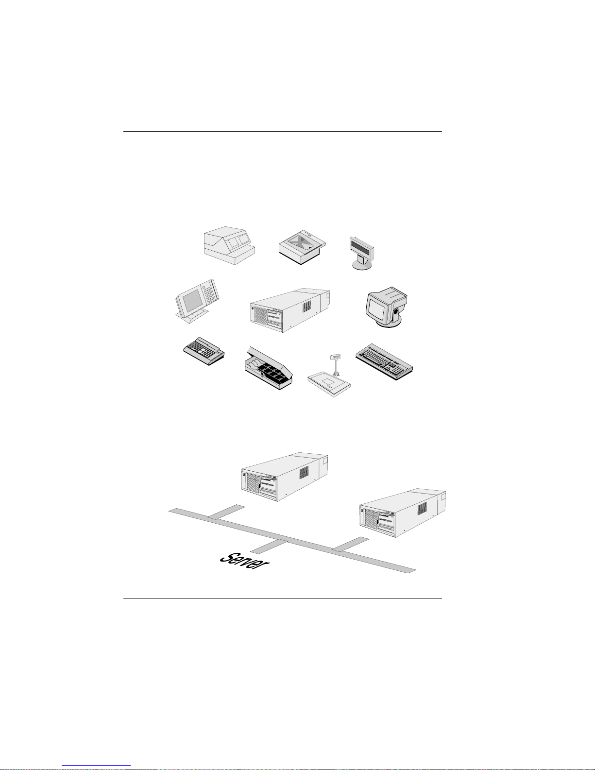
Theindividual POS system
The illustrations below show you how you can expand your modular POS
system - from connecting SNIkey to integrating it into a network.
BEETLE
Printers
SNIkey
Cash drawers
POS keyboards
Scanners
Monitors
Scales
Keyboards
Cashier and customer displays
BEETLE /XL peripherals
BEETLE/XLinanetwork
The individual POS system
GB - 10

Before switching on the system
Unpacking and checking that everything is there
Before switching onthe system
Unpack the parts and check to see whether the delivery matches the
information on the delivery note.
The carton contains the basic unit, which may be equipped with a network
card, floppy drive, hard disk and VGA card, or a combination of these
components.
If damage has occurred during shipping or if the package contents do not
match the delivery note, inform your Wincor Nixdorf sales outlet
immediately.
We advise you to keep the original packaging in case you
transport the device in future (this protects it against
impact and shock).
Setting up the device
Set up the BEETLE /XL POS system where it will not be exposed to
extreme environmental conditions.Protect the device from vibrations, dust,
moisture, heat and strong magnetic fields.
To ensure that the BEETLE /XL has sufficient ventilation, make sure that
the side ventilation slots are kept clear:
❚ Leave at least 100 mm clear to the right of the device.
❚ Leave at least 30 mm clear to the left of the device.
The individual POS system Before switching on the system
GB - 11

The BEETLE /XL is specified for a horizontal mounting. If you install the
system vertically, observe the following:
❚ Stand the device with the ventilator side facing upward.
❚ To ensure proper ventilation, keep the following minimum spaces
clear above and below the device:
Below: 60 mm
Above: 100 mm
❚ A closed area made of nonflammable material (e.g. concrete or
metal) must be located under the vertically mounted BEETLE /XL.
Cabling the BEETLE /XL
Cablingthe BEETLE/XL
To install the devices, proceed as follows (in this order):
❚ Make sure that the power switch on the front of the housing is set to
“off” (i.e. visibly protruding). To do this, you may have to open the
slide cover first (see the illustration on page GB - 15).
100 mm
60 mm
30
Cabling the BEETLE /XL The individual POS system
GB - 12
❚ If necessary, remove the cable cover.
❚ Plug the power cable into the power socket on the BEETLE /XL.
❚ Plug the power cable into a mains socket.
❚ Plug in and secure the data cables.
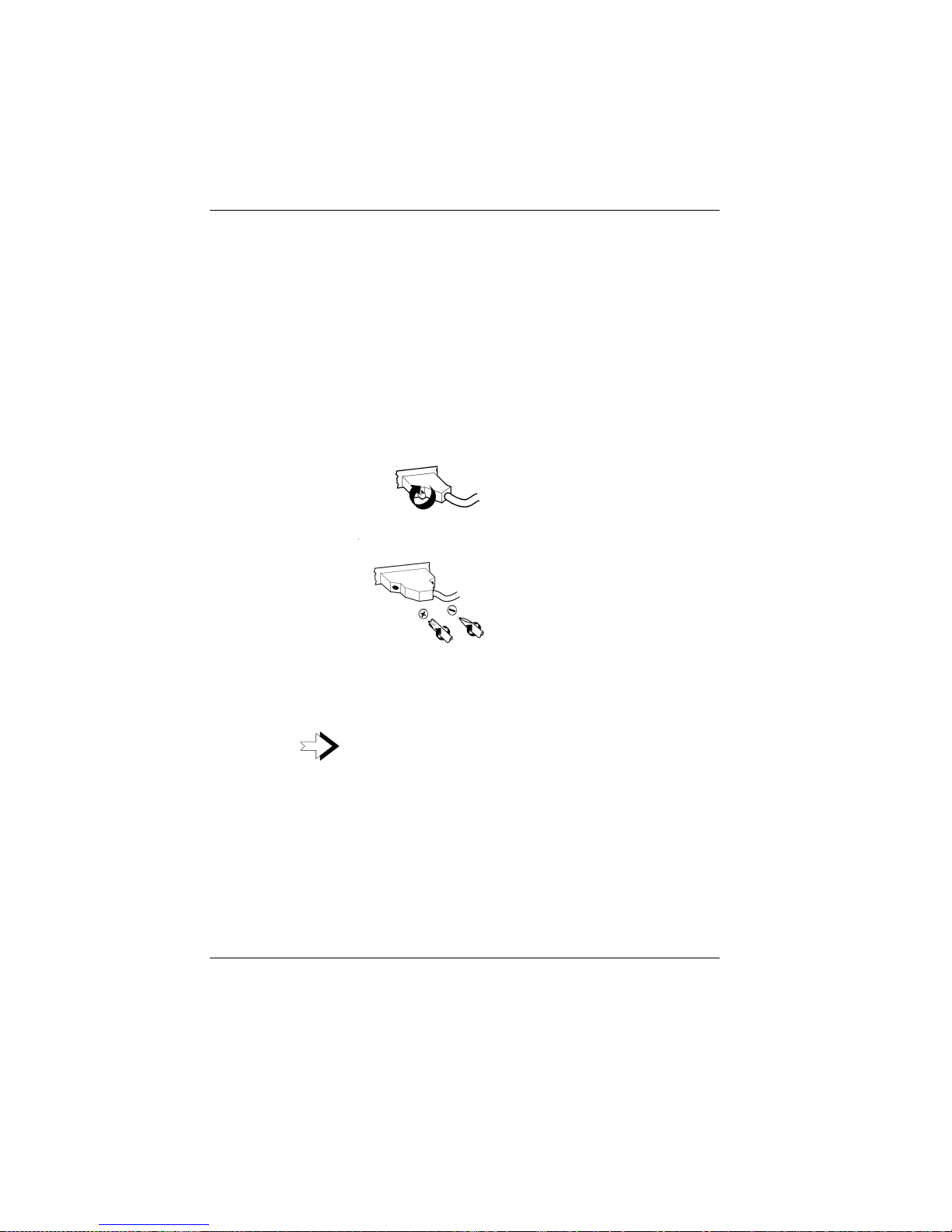
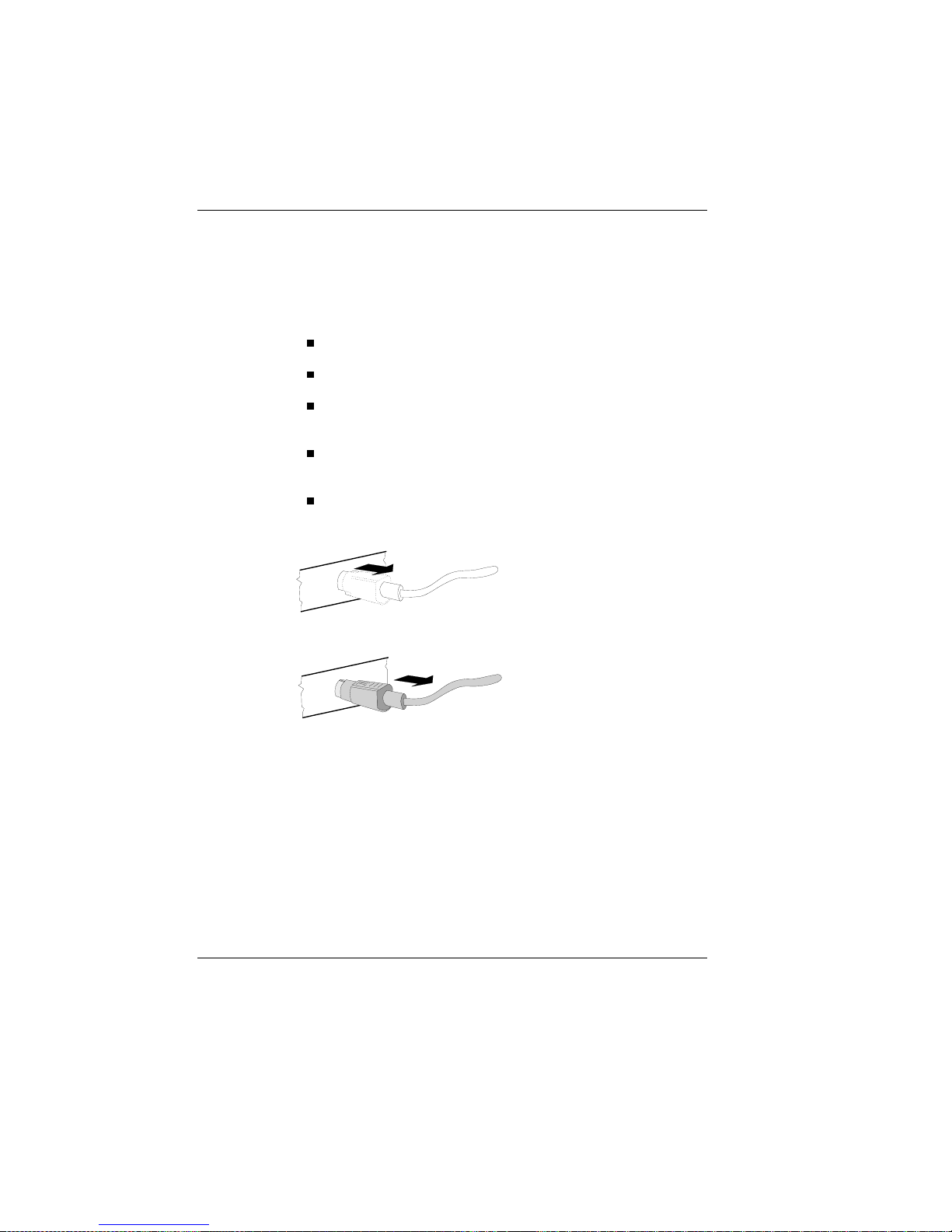
Securing the data cables
Secure interface
connectors with
knurled screws using
your fingers.
Secure interface
connectors with
standard screws
using a screwdriver.
After you have done this, cover the cables by mounting the cable cover
(see next page).
Under no circumstances connect data or power cables
when the system is switched on.
The individual POS system Cabling the BEETLE /XL
GB - 13
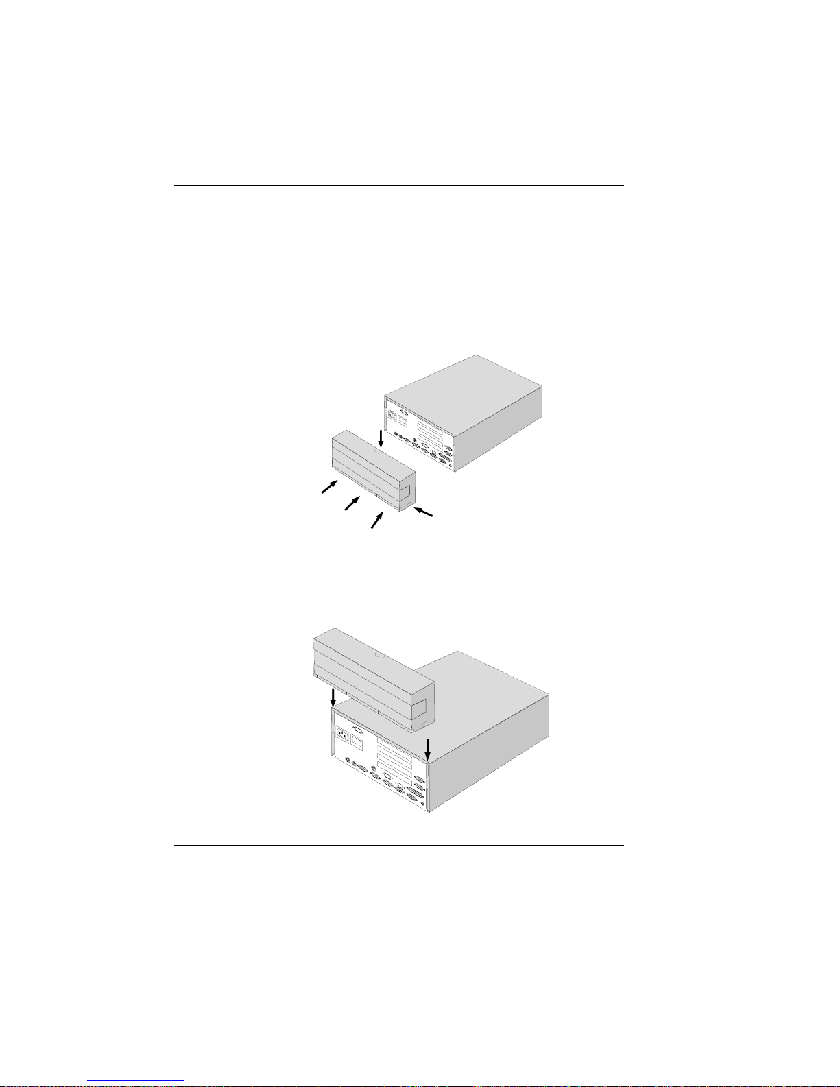
Monting the cable cover
YourBEETLE /XL is shipped with a cable cover.Before you can mount this
on the back of the device, you should remove the connector covers where
necessary, depending on how you want to connect the cables.
Youdo not need a tool for this; these plastic parts can be removed by
hand.
To mount the cable cover,lower it into the guides indicated by arrows in
the illustration. Be careful not to let the cable cover get jammed when you
do this.
Cabling the BEETLE /XL The individual POS system
GB - 14
Connecting to the mains power supply
All devices belonging to the modular BEETLE /XL POS system that have a
separate power cable must be connected to the same electric circuit.
Ensure that the power switch on the POS system housing is off.
Make sure that all data cables on the system unit and periphe-
rals are connected correctly.
Plug all power cables belonging to the BEETLE and the periphe-
rals into the grounded-contact utility power sockets.
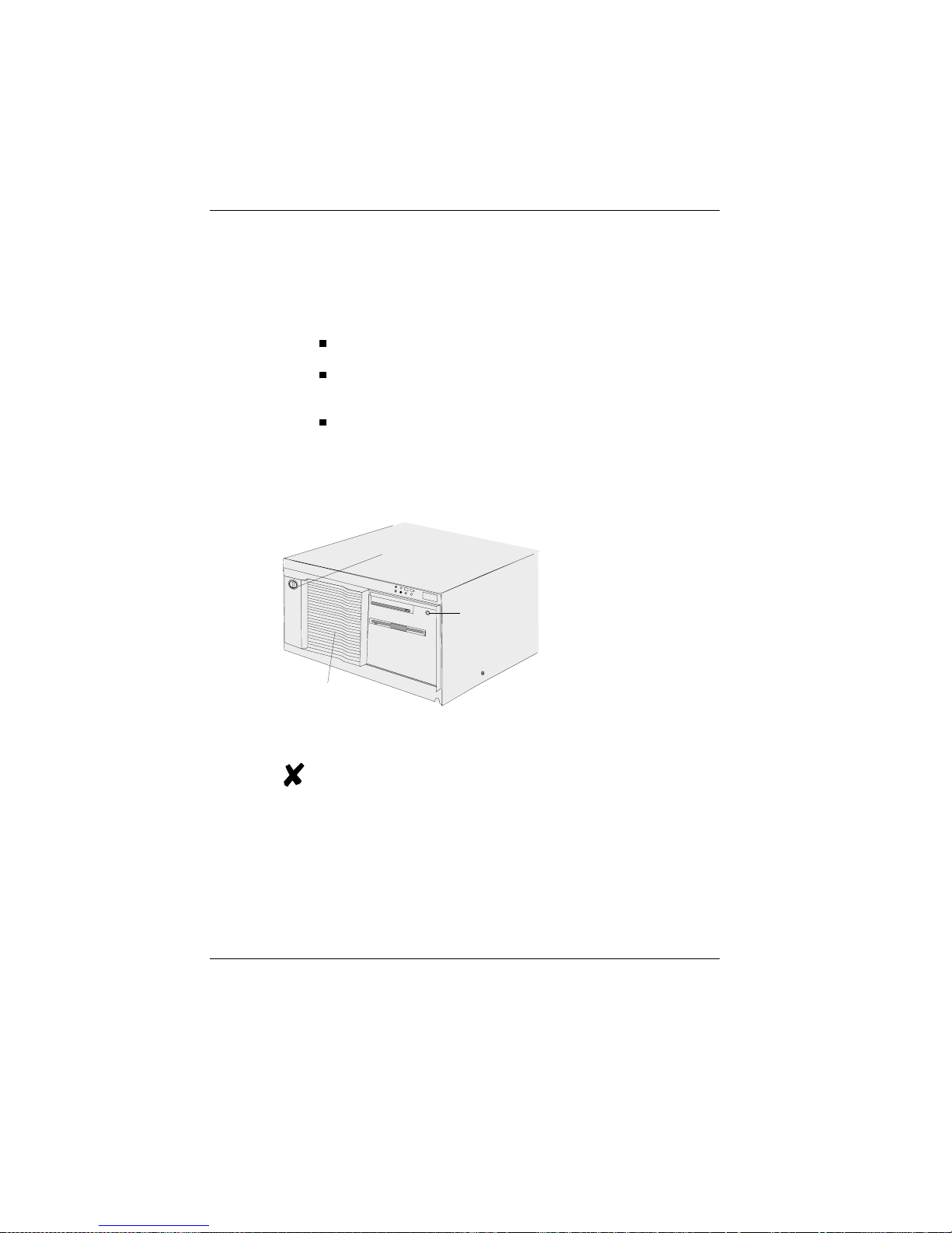
You can now use the
power switch on the
front of the BEETLE
to switch it on. You
may have to unlock
the slide cover and
slide it to the left
before you can do
this.
The power supply unit can be connected to all
conventional power supply networks. It adapts
automatically to the voltage supplied. A fan keeps it
cool. The power-supply unit has a maximum output
of 180W.
On/Off switch
Lock
Slide
BEETLE
The individual POS system Cabling the BEETLE /XL
GB - 15
Disconnecting cables
Disconnectingcables
Never unplug a cable by pulling on the cable itself; always take hold of the
actual plug. To disconnect cables, proceed as follows:
Turn off all power and equipment switches.
Remove the cable cover.
Unplug all data communication cables from the sockets of the
data networks.
Unplug all power cables from the grounded-contact utility power
sockets.
Unplug all cables from the devices.
Use your thumb to pull the plastic cover away from the socket
of the Mini DIN connector. This
releases the lock, and the metal
of the Mini DIN connector becomes visible.
Remove the cable from the sokket.
Basic settings
Ex works, the BEETLE /XL is configured to your order.Your configuration
must be adapted subsequently to support additional devices such as
scanners. For more information please contact your WN branch.
Disconnecting cables The individual POS system
GB - 16
Adjusting the loudspeaker
Adjustingthe loudspeaker
You can set the volume to suit your requirements by means of the volume
control on the back of the POS system housing.
Controller
KYBD
CASHDR COM4* COM3* COM2*
LAN
LPT1
DC24
COM7
COM8
COM1 VGA/LAN/ASYN
The individual POS system Adjusting the loudspeaker
GB - 17
Connecting peripherals
Connecting peripherals
The peripherals mentioned here are available as options; they are not part
of the basic configuration. A separate manual is provided for each
component that can be connected.For more detailed information, please
consult the relevant documentation.
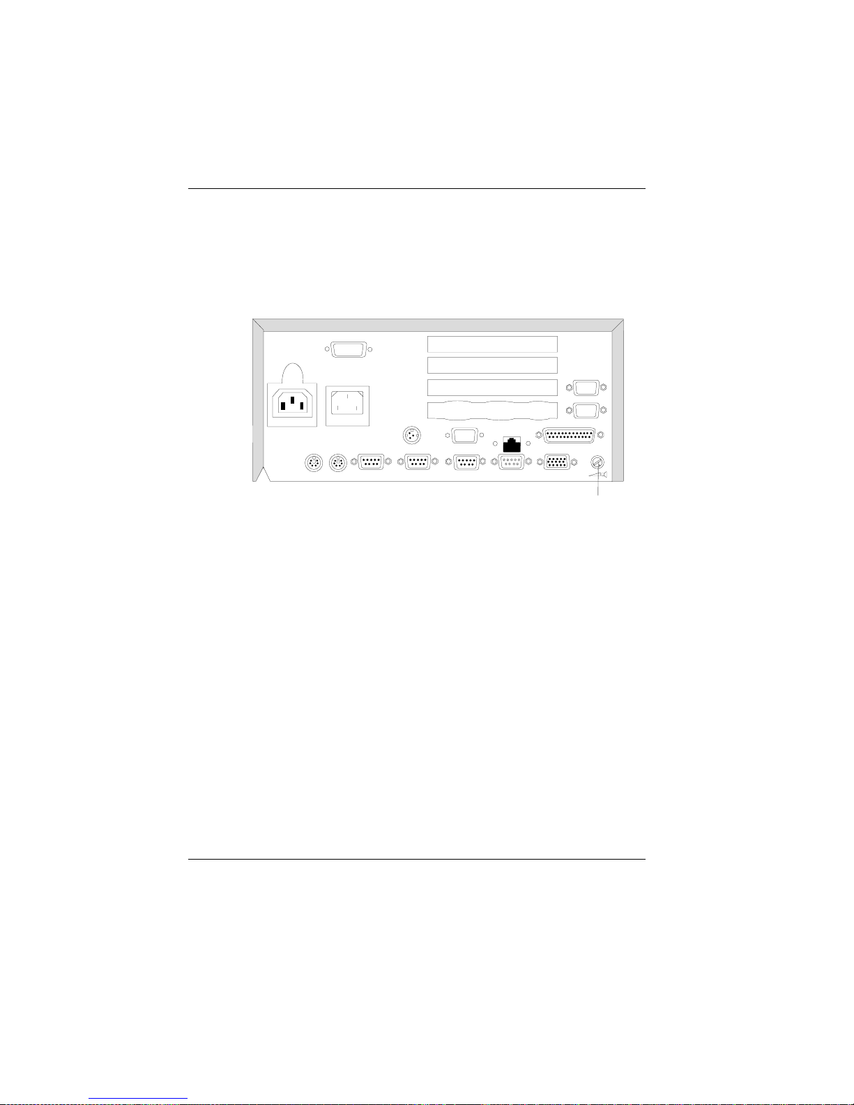
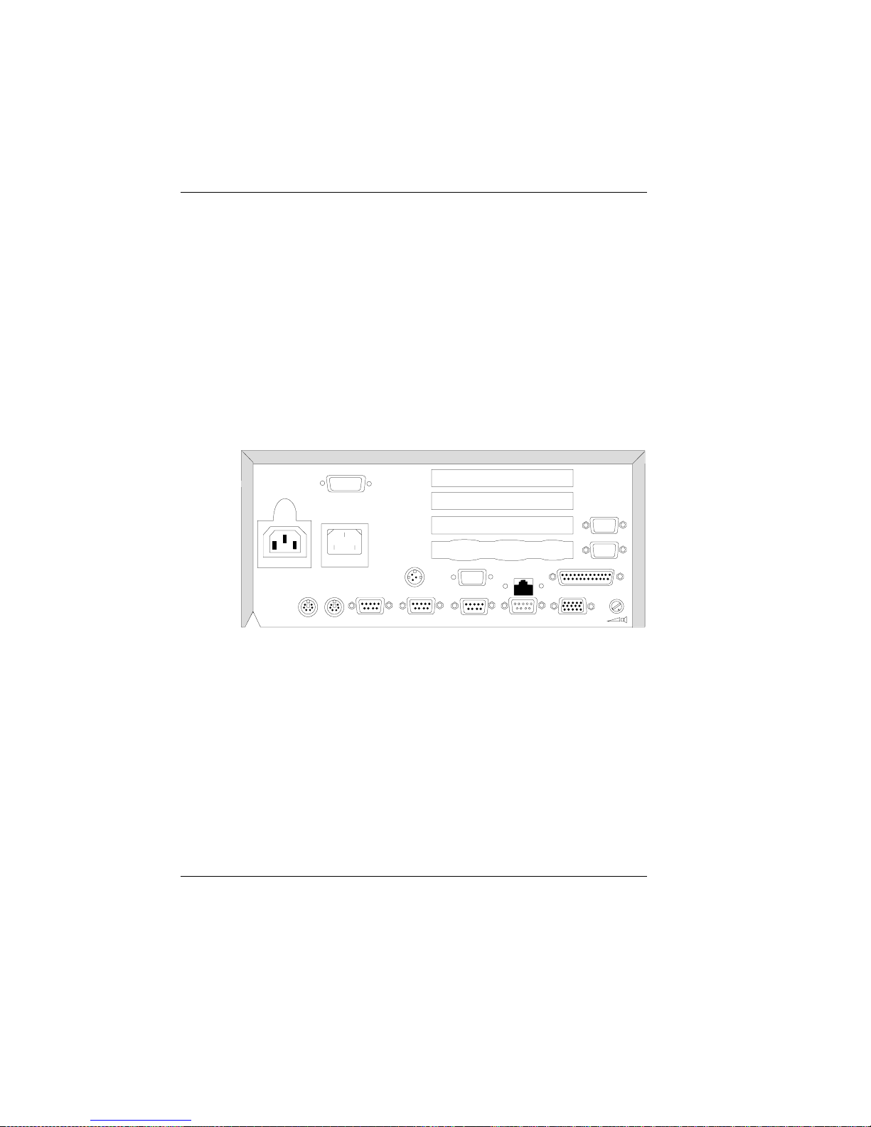
The illustration below shows the rear panel of the BEETLE /XL with the
locations of the connecting sockets and connecting plugs. Toconnect a
monitor, you need a video card. However,you can also run the BEETLE
using only an external cashier display connected to the COM3* port.
To connect your system to a network, you require another expansion card.
Rear panel of the BEETLE /XL
KYBD
CASHDR COM4* COM3* COM2*
LAN
LPT1
DC24
COM7
COM8
COM1 VGA/LAN/ASYN
Connecting peripherals The individual POS system
GB - 18
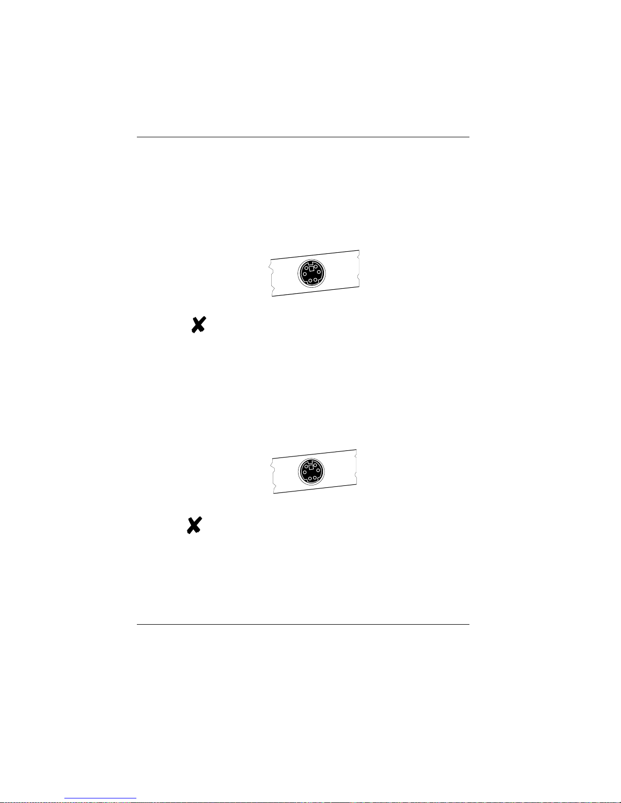
Keyboard (KYBD)
The BEETLE /XL has a 6-pin mini-DIN jack for connecting a keyboard.
Make sure that the connector is plugged firmly into the socket to prevent
malfunctioning. Power is supplied to the keyboard via this socket.Ifyou
wish to connect a standard PC keyboard, you must use a special adapter
cable.Thisis is obtainable from your WN branch.
When using cables with connector locking mechanisms,
take hold of the connector housing when disconnecting
them. Extension cables are available for keyboards.
Cash drawer (CASHDRW)
The BEETLE /XL has a second 6-pin mini-DIN jack for connecting a cash
drawer.Make sure that the connector is plugged firmly into the socket to
prevent malfunctioning. Po weris supplied to the cash drawer via this
socket.
When using cables with connector locking mechanisms,
take hold of the connector housing when disconnecting
them.
The individual POS system Connecting peripherals
GB - 19
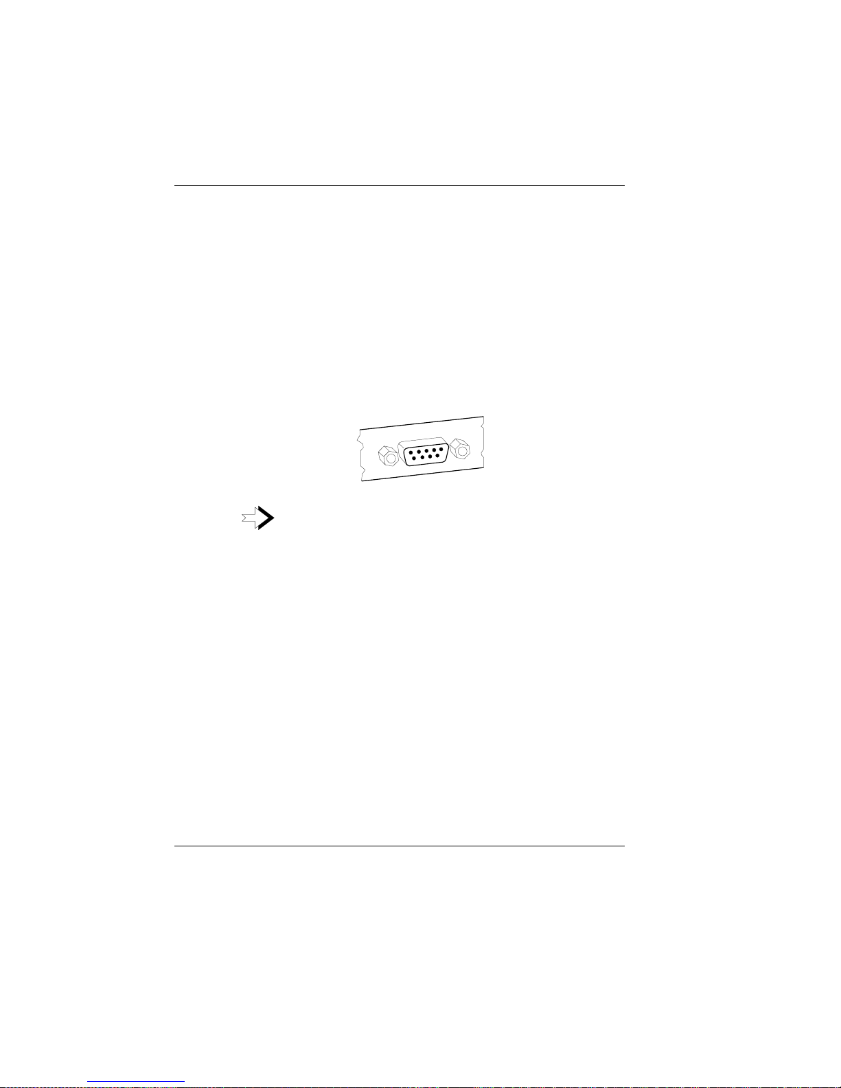
Scanners and scales (COM1 - COM4*)
Depending on the system configuration, scanners and scales without their
own power-supply units are connected to the serial interface COM2*,
COM3* or COM4* (default: COM3*).
Scales with their own power-supply units must be connected to COM1.
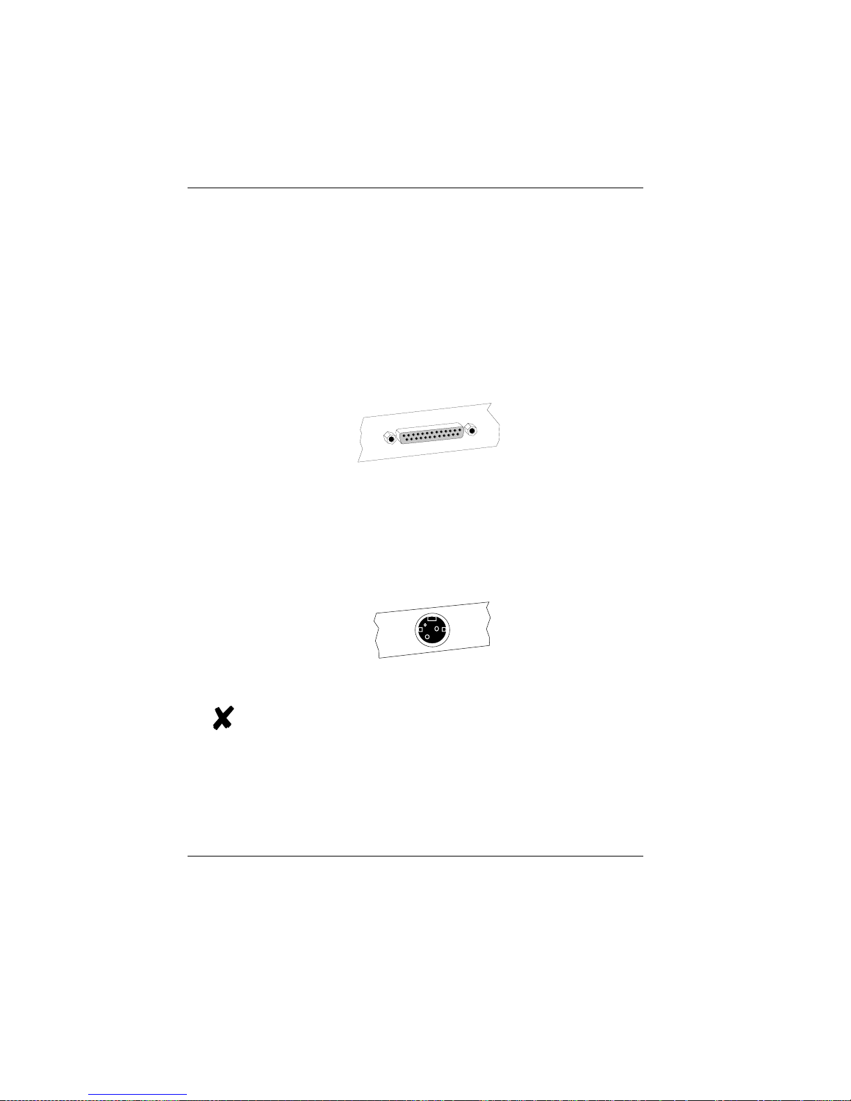
COM1 is a 9-pin D-sub connector, whereas COM2* to COM4* are 9-pin
D-sub sockets.
Make sure that the scanner connector is plugged securely into the socket
to prevent possible malfunctioning. Poweris supplied via this socket.
If you connect scales to the BEETLE /XL that do not
come from Wincor Nixdorf (WN), you have to obtain a
WN license for the driver software.
Connecting peripherals The individual POS system
GB - 20

Customer display (COM2* or COM4*)
Depending on the system configuration, the customer display is connected
to the COM2* or COM4* serial interface of the BEETLE /XL. These are
9-pin D-sub sockets.Makesure that the connector for the customer
display is plugged firmly into the socket to prevent possible malfunctioning.
Power is supplied via this socket.
Cashier display (COM3*)
Connect the cashier display to the COM3* serial interface.This is a 9-pin
D-sub socket.
Make sure that the connector for the customer display is plugged firmly
into the socket to prevent possible malfunctioning. Poweris supplied via
this socket.
The individual POS system Connecting peripherals
GB - 21
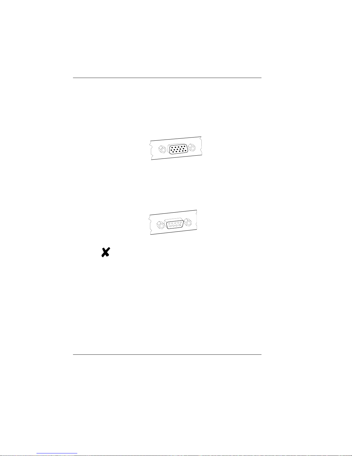
Monitor
If a VGA card is installed, you can connect a monitor to the BEETLE /XL
via the 15-pin D-sub socket of the VGA card.Power is supplied to the
monitor via the rubber socket on the back of the BEETLE /XL.
Connecting standard PC peripherals (COM1)
Youcan connect standard peripherals to the BEETLE /XL via the COM1
serial interface.
Make sure that all additional devices have been tested
for RFI suppression pursuant to the legal requirements
of your country.
Connecting peripherals The individual POS system
GB - 22
Network
If a network card is installed, the system can be connected to a network
(LAN) from the rear panel.If a LAN card is not installed, there is a dummy
cover at this point on the rear panel (see also configuration variations).
Printer (LPT1 / 24V, 4A)
You can connect a printer to the standard parallel interface LPT1.
In addition, suitable POS printers can be supplied with power via a
low-voltage socket (24V, max. 4A). A connecting cable with a HOSIDEN
connector is required for this. Do not connect a HOSIDEN plug when the
system is turned on!
Connect only cable to the 24V connector which are marked with DP-1 or
DP-2.
The individual POS system Connecting peripherals
GB - 23
 Loading...