

Wincor Nixdorf BEETLE/20 User Manual

BEETLE /20
PC based Cash Register
User Manual
BEETLE

BEETLE /20
PC based Cash Register
User Manual
Edition March 2000

MS-DOS®,Microsoft®, Windows 3.x®, Windows 95®and Windows NT®are registered trademarks
of Microsoft Corporation.
BEETLE
®
is a registered trademark of the Wincor Nixdorf GmbH.
Copyright © Wincor Nixdorf GmbH &Co. KG, 2000
The reproduction, transmission or use of this document or its contents is not permitted without
express authority.
Offenders will be liable for damages.
All rights, includingrights created by patent grant or registration of a utility model or design, are reserved.
Delivery subject to availability; technical modifications possible.

Contents
Manufacturer’s Certification ...................................................................1
FCC-Class A Declaration............................................................................1
Tested Safety.............................................................................................. 2
Important information ..................................................................................2
Introduction ............................................................................................... 5
About this manual........................................................................................6
Recycling the BEETLE /20.......................................................................... 8
BEETLE /20 configuration options.......................................................... 9
The BEETLE /20 in a network...................................................................11
Before switching the system on................................................................12
Unpacking and checking the delivery..................................................... 12
Setting up the device ..............................................................................12
Cabling the BEETLE............................................................................... 12
Securing the data cables ........................................................................ 13
Connecting to the mains power supply...................................................14
Disconnecting cables..............................................................................15
Basic settings..........................................................................................16
Adjusting the volume...............................................................................16
Connecting peripherals ............................................................................. 17
Keyboard................................................................................................. 18
Cash drawer............................................................................................18
Scanner................................................................................................... 19
Customer display.................................................................................... 19
Monitor ................................................................................................... 20
Standard PC peripherals and scales...................................................... 20
Network................................................................................................... 20
Printer (integrated)..................................................................................21
Printer (LPT1 / V24, 24V, max. 2A)........................................................ 21
Fixing the cable cover...............................................................................22

BEETLE /20 modular...............................................................................23
BEETLE /20 modular with swivel arm.......................................................24
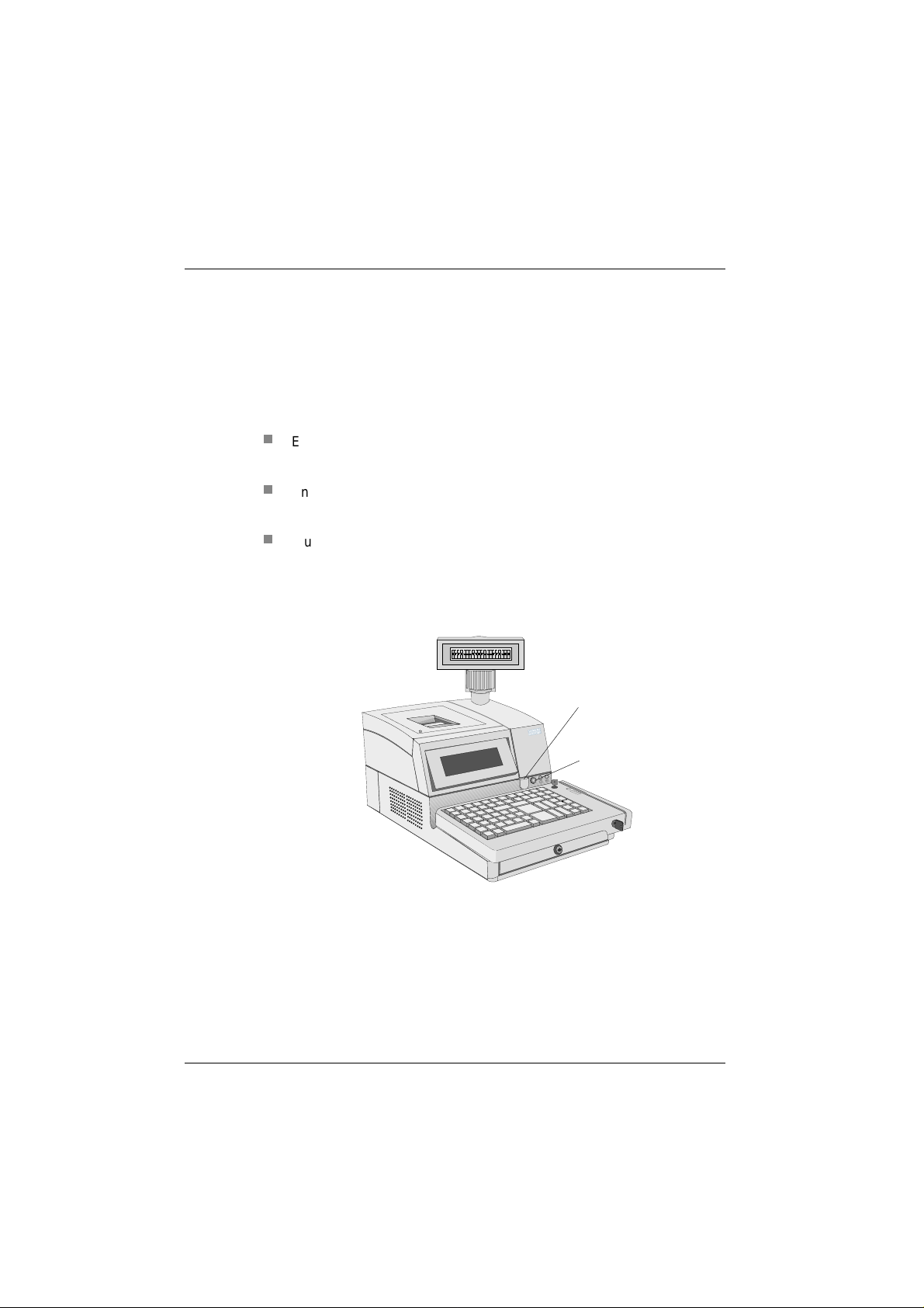
BEETLE /20 Overview ............................................................................25
Customer display.....................................................................................27
Cashier display........................................................................................28
Changing the window of the cashier display .............................................28
One-station printer ..................................................................................32
Changing the receipt roll ...........................................................................32
Changing the ribbon cassette....................................................................34
Changing the print head ............................................................................36
Changing the printer..................................................................................37
One-station printer with winder .............................................................38
Changing the receipt and journal roll ........................................................38
Two-stations printer................................................................................41
Changing receipt and journal paper rolls...................................................41
Changing the receipt roll.........................................................................43
Changing the journal roll.........................................................................45
Adjusting the paper end detectors.............................................................47
Inserting a validation..................................................................................49
Changing the ribbon cassette....................................................................50
Clearing paper jams...................................................................................51
Changing the stamp...................................................................................53
Adding stamp ink.......................................................................................54
Changing the printer .................................................................................55
Changing the journal window ....................................................................56
Care and Cleaning...................................................................................58
Care of the BEETLE /20............................................................................58
Cleaning the printer ...................................................................................58
Cleaning the document detection sensor .............................................59
Cleaning the printer motor timing disk.....................................................60

The BEETLE card (optional)................................................................... 62
Inserting the BEETLE card........................................................................ 63
The card type ............................................................................................63
Write protection for BEETLE cards........................................................... 64
Floppy disk drive.....................................................................................65
General...................................................................................................... 65
Inserting the floppy disk ............................................................................ 66
Removing the floppy disk .......................................................................... 67
The central processing unit ................................................................... 68
General...................................................................................................... 68
Interfaces................................................................................................... 69
Loudspeaker..............................................................................................69
Non-volatile RAM (NV RAM)..................................................................... 69
Main memory............................................................................................. 70
Connection options.................................................................................... 70
Connecting a hard disk ............................................................................ 70
Free slots................................................................................................... 70
Additional slot on the central processing unit ........................................... 70
Power supply unit .................................................................................. 71
Power supply unit and accumulator battery ............................................. 71
Keyboard..................................................................................................72
Keyswitch ..................................................................................................72
Swipecard reader......................................................................................73
Cleaning instructions.................................................................................73
Software ................................................................................................... 74
Operating system...................................................................................... 74
Retail device interface............................................................................... 74
Application programs ................................................................................74
Retail message handler ............................................................................74
Retail presentation manager..................................................................... 75
Retail transaction manager.......................................................................75
High frequency table ................................................................................ 75
Hash file access method ..........................................................................75

Putting the system into operation .........................................................76
Startup behavior ........................................................................................76
Output of MS-DOS system error messages..............................................79
Power On Self Test (POST) ......................................................................80
BIOS setup ...............................................................................................81
Memory......................................................................................................86
LPT1 mode................................................................................................86
Power management ..................................................................................86
COM interfaces..........................................................................................87
Interrupts....................................................................................................88
Shadowing.................................................................................................88
Cache.........................................................................................................88
Additional I/O adapters..............................................................................89
Appendix...................................................................................................91
Technical data for the BEETLE/20 ............................................................91
Central processing unit..............................................................................92
ASYNC controller.......................................................................................93
VGA controller ...........................................................................................93
LAN controller............................................................................................94
One-station printer.....................................................................................94
Receipt paper..........................................................................................95
Printable area (the values are indicated in mm) .....................................95
One-station printer with winder..................................................................96
Receipt-/Journal paper............................................................................96
Two-stations printer...................................................................................97
Validation paper (single-Ply or multi-ply: original and 1 copy)................97
Receipt-/Journal paper............................................................................98
Single-ply ..............................................................................................98
Multi-ply: Original and 1 copy................................................................98
Printable area (the values are indicated in mm) .....................................99
Journal Paper........................................................................................99
Receipt Paper .......................................................................................99
Installing an expansion card....................................................................100
Remove the housing .............................................................................100
Take off the metal cover........................................................................102
Installing an expansion card..................................................................103
Installing a submodule.............................................................................104
Changing the hard disk............................................................................106
Changing the battery ...............................................................................107
The configuration label ............................................................................108

Error messages.....................................................................................109
MS-DOS critical errors ............................................................................ 109
POST (Power On Self Test) error messages .........................................110
Phoenix BIOS POST and startup messages........................................112
Additional messages...............................................................................115
MCBATT status messages..................................................................... 115
Error messages via blink codes (one station printer) .............................116
Error detection ..................................................................................... 116
Error display..........................................................................................116
Error messages via blink codes (two station printer)..............................117
LED “ERROR” ......................................................................................117
All LEDs ...............................................................................................118
Glossary................................................................................................. 120
Index.......................................................................................................123

Manufacturer’s Certification
The device complies with the requirements of the EEC
directive 89/336/EEC with regard to “Electromagnetic
compatibility” and 73/23/EEC “Low Voltage Directive”.
Therefore, you will find the CE mark on the device or packaging.
FCC-Class A Declaration
This equipment has been tested and found to comply with the limits for a
Class A digital device, pursuant to part 15 of the FCC Rules. These limits
are designed to provide reasonable protection against harmful interference when the equipment is operated in a commercial environment.
This equipment generates, uses, and can radiate radio frequency energy
and, if not installed and used in accordance with the instruction manual,
may cause harmful interference to radio communications.
Operation of this equipment in a residential area is likely to cause harmful
interference in which case the user will be required to correct the interference at his own expense
Le présent appareil numérique ne genère pas de bruits radioélectriques
dépassant les limites applicables aux appareils numérique de la “Class A”
prescrites dans le Règlement sur le brouillage radioélectrique édicte par le
ministère des Communications du Canada.
GB - 1
Important information
Tested Safety
When you handle boards fitted with ESDs, you must observe the following
points under all circumstances:
n
You must always discharge yourself (e.g. by touching a grounded object) before working with boards containing ESDs.
n
The equipment and tools you use must be free of static charges.
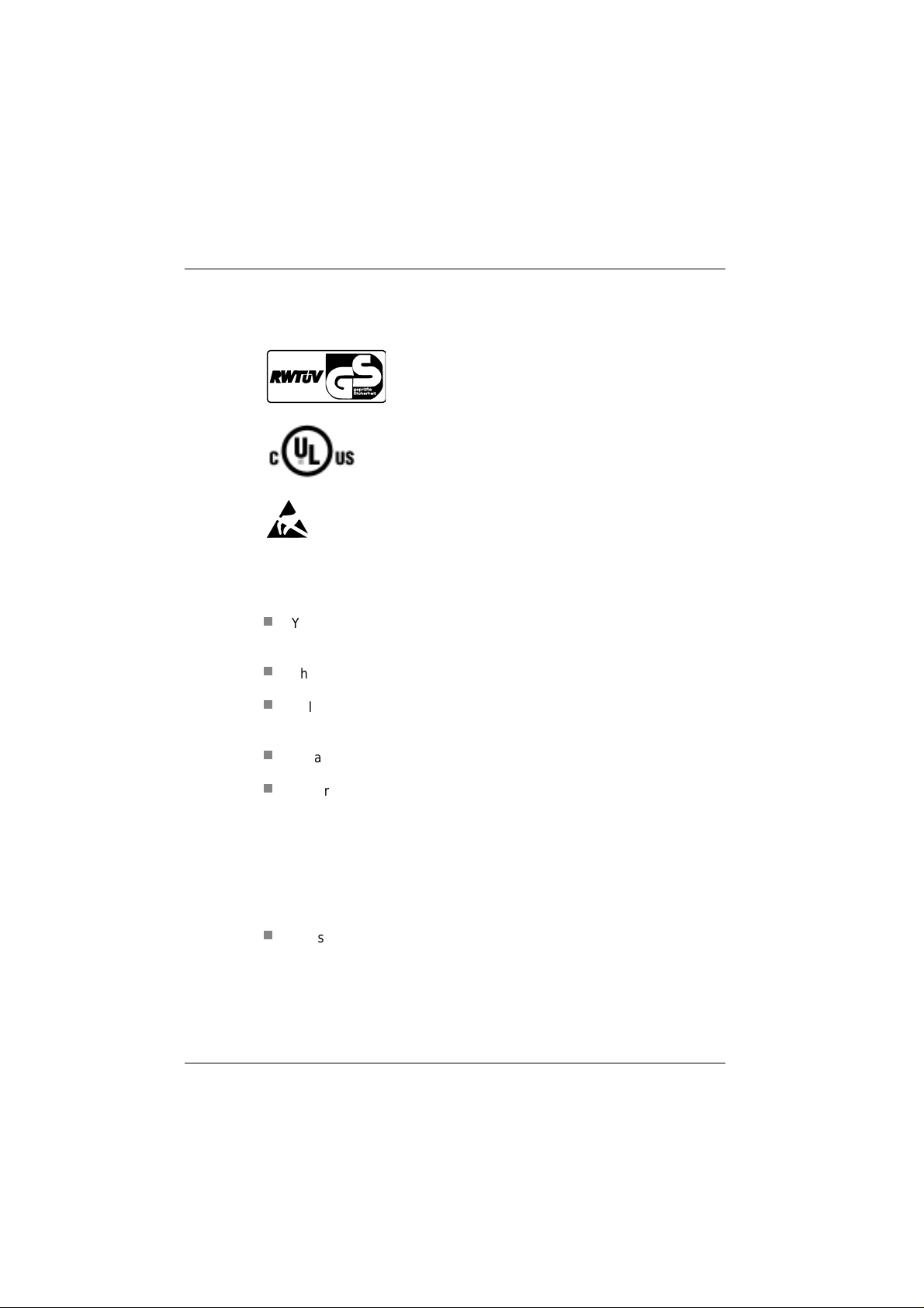
The BEETLE /20 has been provided with the symbol
for ”Tested Safety”
In addition, the BEETLE has received the UL and
cUL symbols.
Boards with ESDs (Electrostatic Sensitive Devices)
may be identified by this label.
n
Pull out the power plug before inserting or pulling out boards containing ESDs.
n
Always hold boards with ESDs by their edges..
n
Never touch pins or conductors on boards fitted with ESDs.
Important information
The BEETLE /20 POS system fulfills all the relevant safety requirements
for data processing equipment.
n
If this device is taken to the room where it is to be used from a cold
environment, condensation may form. Before it is put into operation,
the device must be completely dry; you should therefore wait for an
acclimatization period of at least two hours.
GB - 2
Importantinformation

Important information
n
This device is equipped with a safety-tested power cable and may be
connected only to a prescribed grounded-contact utility power socket.
n
When setting up the device, ensure that the power socket on the device and the grounded-contact utility power socket can be easily accessed.
n
To fully disconnect the device from the mains voltage, switch it off and
remove the power plug.
n
Ensure that no foreign objects (such as paper clips) get inside the device, since this can lead to electric shocks or short circuits.
n
In case of transporting your BEETLE /20 never take hold of the cable
cover or the keyboard but always of the sides.
n
To ensure that the device is well ventilated and does not overheat,
make sure that its ventilation slots are not obstructed.
n
Never connect or disconnect data cables during a thunderstorm.
n
Protect the device from vibrations, dust, moisture and heat. Set up
your BEETLE system in a splash water protected area.
n
Dispose of consumables, such as the battery, in the appropriate way,
so as not to harm the environment.
n
There is a lithium battery on the system board. Only authorized and
trained personnel should change this. There is a risk of explosion if it
is not changed properly.
n
The lithium battery must be disposed of in accordance with local regulations for special waste.
n
In the event of an emergency (e.g. damage to the housing or power
cable, or liquid or foreign bodies in the device), switch the device off
immediately, disconnect the power plug, and get in touch with the
Wincor Nixdorf (WN) customer service or your dealer’s authorized service partner.
GB - 3

Important information
n
Your BEETLE POS system is the result of modern technical innovation. So please see for according structural and technical surroundings
to guarantee a faultless and efficient work of your BEETLE.
Therefore, you should connect your BEETLE or other IT-devices only
to power supply systems with separately guided protective earth conductor (PE). This kind of electricity system is known as TN-S network.
Do not use PEN conductors!
Please also observe the recommendations of the norm DIN VDE
0100, Part 540, Appendix C2 as well as EN50174-2, §5.4.3.
Thus you can help to avoid possible malfunctions
Only authorized, trained personnel may carry out repairs to
the device. If you open the device without authorization or
carry out repairs improperly, you not only expose yourself
to considerable danger; you also lose all your rights to
make warranty and liability claims.
GB - 4

Introduction
As the first representative of the new PCR (PC-based Cash Register) generation, the BEETLE /20 provides the link between POS and ECR
systems.
Fit for the POS future: That was the underlying concept of developing the
BEETLE /20! The basic variants consist of compact and modular systems.
The compact systems unite all the essential POS components including a
POS printer, a customer and a cashier display in one housing. With the
modular systems, on the other hand, you have the free choice and configurability of printers and displays.
With the BEETLE /20, in addition to being able to store data on a hard disk
or floppy disks, you also have the option of using BEETLE cards to save
data. This ensures a high level of data security and protection against data
manipulation.
For monitor applications we offer an integrated monitor on a swivel arm.
The BEETLE /20 can be networked.
It is quick to install, easy to use, and provides extensive functionality. At
the same time, it requires a minimum of maintenance effort.
GB - 5

About this manual
About this manual
This manual will help you get to know your POS system and serve as a reference work. The detailed table of contents and index will enable you to
find the information you need quickly and easily.
After the two beginning chapters the following section describes:
■
Everything you have to do before switching the terminal on.
■
How to connect peripherals to the BEETLE /20.
The following chapter contents the graphs of BEETLE/20 systems:
■
modular and
■
with swivel arm.
The fourth chapter contains:
■
An overview of the components of your BEETLE POS system.
Aboutthis manual
GB - 6
The fifth up to ninth chapter contain:
■
The components like cashier display and printer. You will find
detailed descriptions of things you will have to do again and
again, such as changing the receipt roll in the chapter of the
printer.
The tenth section provides:
■
The subject ´care and cleaning´ of your BEETLE system, to offer you an overview in a central passage.

About this manual
The following five sections explain other hardware components, for example keyboard and BEETLE card.
The next chapter provides:
■
A quick overview of the system software of your BEETLE /20
POS system.
The following sections explain:
■
How to put the system into operation.
■
The BIOS setup.
You require technical knowledge in order to understand these chapters.
The appendix contains:
A list of the most important technical data and discription of installations
for example installing an expansion card.
A list of the possible error messages and a glossary, which also contains
important abbreviations, you will find in the last two sections of this book.
This sign draws your attention to important information in
the manual.
This sign is used to draw your attention to cautionary notes.
Since the type and scope of the application programs used depend on
what each customer chooses, the manual does not deal with software
except for the setup program and a brief description of the most important
WN programs.
Separate manuals are included in the delivery for the peripherals that can
be connected, which is why this equipment is not described in any detail
here. Please refer to the relevant manuals.
GB - 7

Recycling
Recycling the BEETLE /20
The recyclable parts of the housing are identified as such, and much of
the precious metals can be recovered as well. This saves energy and
valuable raw materials.
There are still a few parts that are not reusable. Wincor Nixdorf disposes
of these in an environment-friendly manner in a Recycling Center, which
has ISO 9001 certification.
During its active life, your BEETLE POS system uses consumables that
have to be disposed of in an ecologically sound manner. Wincor Nixdorf
provides a recycling box for used ribbons, which you should set up at your
company. The very reasonable price for the box also includes the collection and complete recycling of the ribbons. Contact your Wincor Nixdorf
branch or authorized dealer for information.
Recycling
Recycling begins at manufacture, not at
disposal.
Our BEETLE /20 system is made without
CFCs or chlorinated hydrocarbons, and
the great majority of the parts and
materials used can be recycled.
GB - 8
If you have any questions about environmental protection
Wincor Nixdorf’s environmental protection section in Paderborn,
Germany, will be glad to help.
Please contact:
Fax: +49 (0) 5251 8-26709
email: referat.umweltschutz@wincor-nixdorf.com

BEETLE /20 configuration options
This chapter introduces all the equipment that is currently available for the
BEETLE /20. You can:
■
Connect an external alphanumeric customer display.
■
Connect an external cashier display and various cash drawers.
■
Use different types of scanners, such as distance, touch or sta-
tionary scanners.
■
Use the SNIkey.
■
Connect scales and scanner scales (please comply with the offi-
cial certification regulations).
■
Select from a range of printers.
■
Use a swivel arm with monitor on the BEETLE/20 modular.
■
Connect a POS keyboard (with or without a magnetic card rea-
der and waiter keylock) or a PC keyboard.
■
Use a catering keyboard with/without a waiter keylock.
■
Connect a monitor to the BEETLE /20.
■
Order the BEETLE /20 with a financial controller.
■
Install a LAN connection to integrate the BEETLE in a network,
connect a modem, and thus transfer data.
The illustrations below show you the options available for expanding your
BEETLE /20 system - from a scanner to integration in a network.
GB - 9
Configuration options
Configurationoptions
Scanners
SNIkey
Cashier displays
Cash drawers
Customer displays
Monitors
Printers
Scales
GB - 10
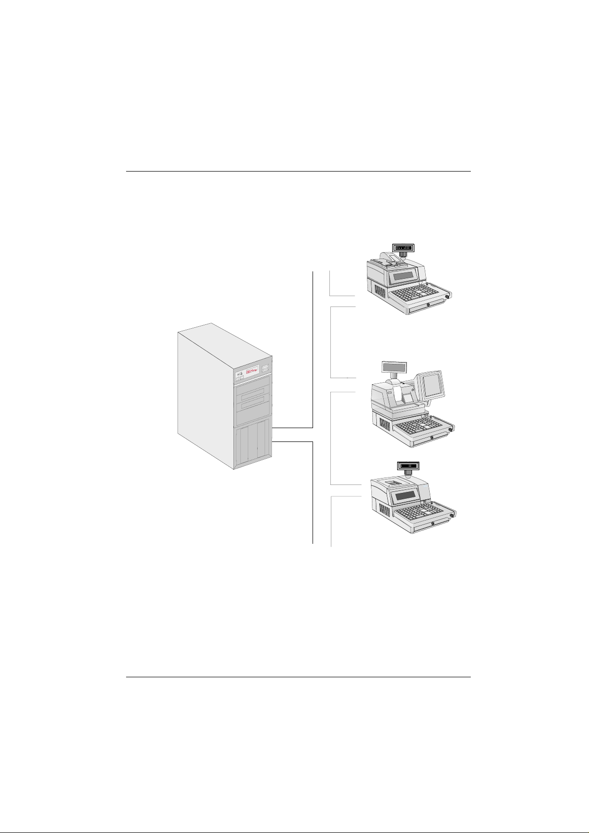
The BEETLE /20 in a network
BEETLE /20 in a network
BEETLE/20 in a network
Ethernet
10 Base T
Server
GB - 11

Before switching the system on
Before switching the system on
Unpacking and checking the delivery
Beforeswitching the systemon
Unpack everything, and check that what has been delivered corresponds
to what is specified on the delivery note.
If you find that anything has been damaged during transportation or that
there are differences between the delivery and what is on the delivery
note, please notify your SNI branch or dealer immediately. We recommend that you keep the original packaging in case you want to transport the device again (the packaging protects it against knocks and
bumps).
Always take hold of the sides of your BEETLE /20 and never of the cable cover or the keyboard as both are movable
and can be removed without any tools
Setting up the device
Set up the BEETLE POS system where it will not be subjected to extreme
ambient conditions. Protect it from shocks, dust, moisture, heat and powerful magnetic fields.
Cabling the BEETLE
Install the devices in the following order:
n
Ensure that the device is switched off before you connect the cables.
n
Connect the power cable to the BEETLE /20.
n
Connect the plug of the power cable to a grounded-contact utility power socket.
GB - 12
Make sure that the ventilation slots at both sides of the
BEETLE POS system are clear (at least 50 mm on both sides) to ensure that the device has adequate ventilation.
n
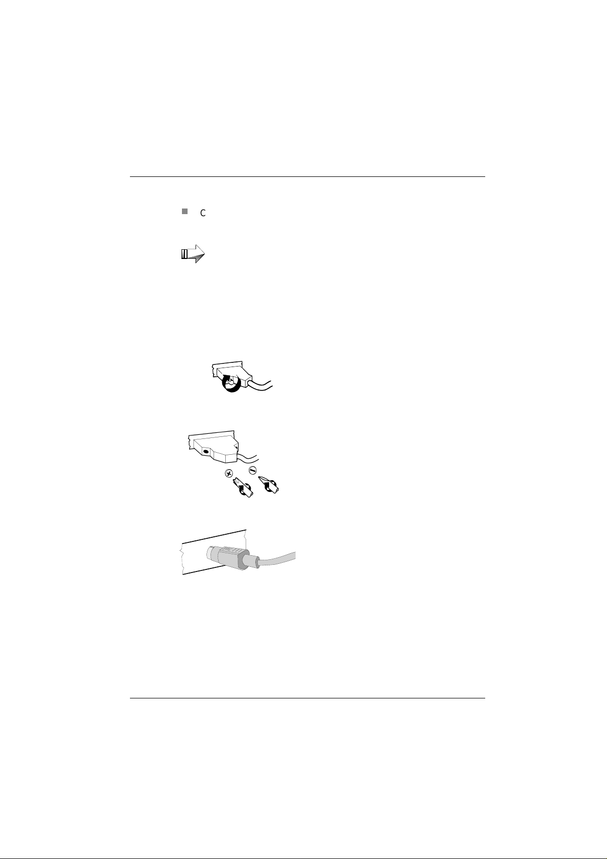
Connect and secure the data cables.
Securing the data cables
Before switching the system on
Never connect or disconnect data cables during a thunderstorm.
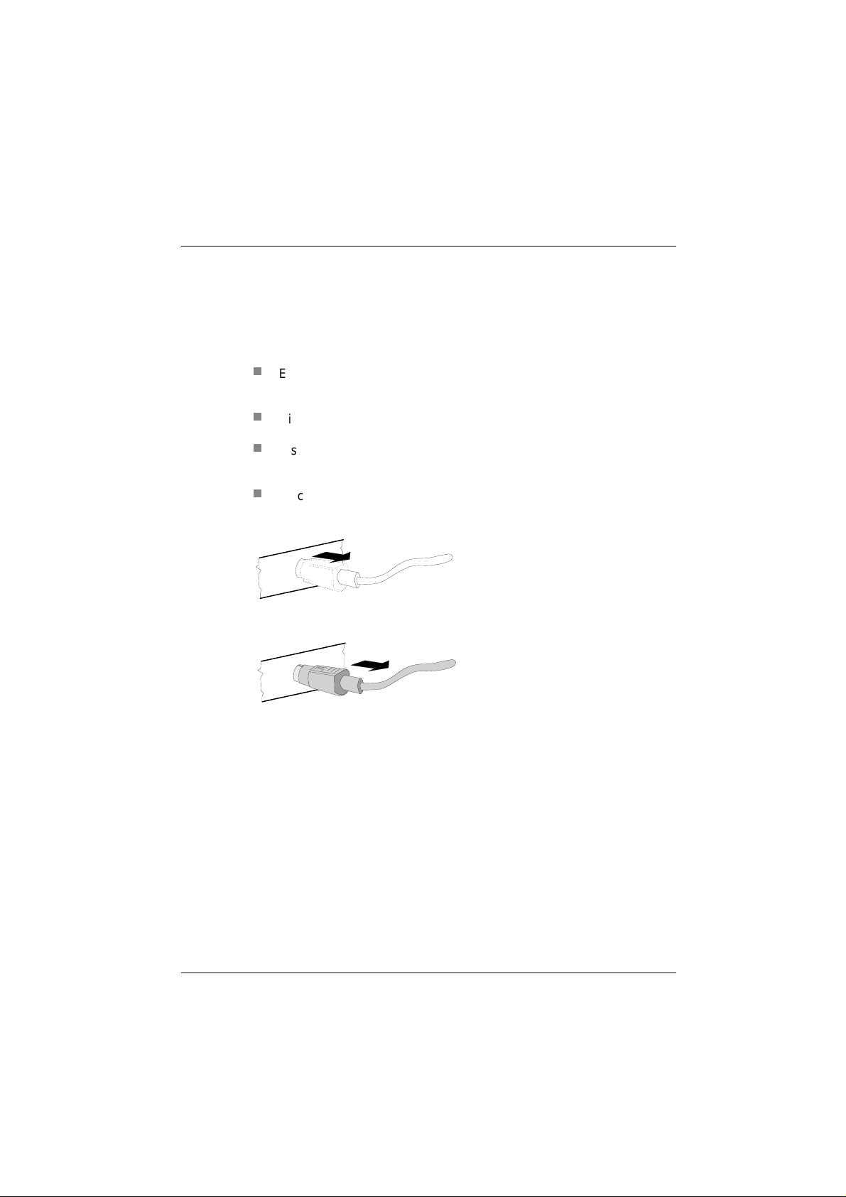
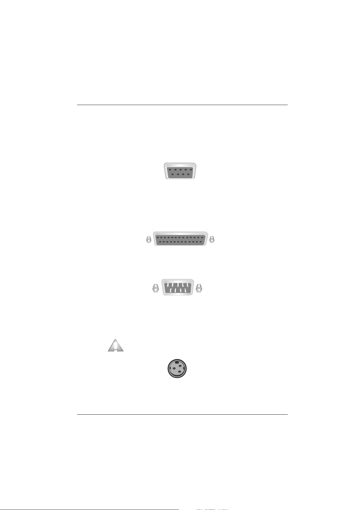
Interface connectors
with knurled screws can
be secured manually.
Interface connectors
with screws can be
secured with a screwdriver.
Mini-DIN plugs lock in
when you insert them.
GB - 13
Connecting to the mains power supply
Connecting to the mains power supply
All devices that belong to the BEETLE /20 and have a separate power cable must be connected to the same circuit. The terminal automatically identifies the local mains voltage when it is switched on, and there is therefore
no need for you to make any adjustments in or on the device.
n
Ensure that the device is switched off (the on/off switch must be out).
To access the switch, you may have to push the cover aside.
n
Ensure that all data cables on the system unit and the peripherals are
properly connected.
n
Plug all the power cables of the peripherals and the BEETLE /20 into
the grounded-contact utility power sockets.
You can now switch the BEETLE /20 on using the switch at the front of the
housing.
Connectingto themains powersupply
Cover (adjustable)
GB - 14
On/Off switch
Disconnecting cables
Never unplug a cable by pulling the cable itself; always hold the plug. To
disconnect the cables, proceed as follows:
n
Ensure that all the power and equipment switches are in the off position.
n
Disconnect all the data cables from the sockets of the data networks.
n
Disconnect all the power cables from the grounded-contact utility power sockets.
n
Disconnect all cables from the devices.
Disconnecting cables
Disconnectingcab les
Mini-DIN plugs remain
plugged in until they
are released. First
push the cable to the
plug housing and then
use your thumb to pull
the plastic cover of the
plug housing away
from the connecting
socket. This releases
the lock, and the metal
of the plug becomes
visible.
Remove the plug from
the connecting socket.
GB - 15

o
eco
Disconnecting cables
Basic settings
The BEETLE /20 is configured in the factory to the specifications on your
order. Additional equipment such as scanners must be adapted to your
configuration subsequently. Contact your technician or customer service.
Adjusting the volume
You can adjust the volume using the control at the bottom on the right on
the back of the terminal housing.
COM8
COM7
GB - 16
LPT1
VGA/LAN/ASYN
lum
V
ntrol
Connecting peripherals
The illustration shows part of the rear panel of the BEETLE /20, with the
position of the connecting sockets and connectors. A SVGA/VGA graphics
adapter is necessary to connect a monitor. If you install a network adapter,
you can also connect the system to a network.
Connecting peripherals
Connectingperipherals
Socket
AT-SLOT
AT-SLOT
Mains supply
DC24
CASHDR COM4* COM3* COM2* COM1
KYBD
LAN
VGA/LAN/ASYN
COM8
COM7
LPT1
Some of the peripherals mentioned in the following pages are availabe as
options. There are separate manuals for all the equipment that can be connected, so if you want more detailed information, please refer to the relevant manual.
Before connecting peripherals, you must ensure that all power and equipment switches are in the off position. Otherwise, the central processing unit (CPU) of the POS system
may malfunction.
If the peripherals are supplied with power through the system (+5V/+12V), you must ensure that the maximum permissible current for the entire configuration is not exceeded.
GB - 17

Connecting peripherals
Keyboard
The BEETLE POS system has a 6-pin mini-DIN socket for connecting a
keyboard (KYBD). To prevent malfunctioning, make sure that the plug is
firmly plugged into the socket. The keyboard is supplied with power via
this socket.
Cash drawer
The BEETLE POS system has a second 6-pin mini-DIN plug for connecting a cash drawer (CASHDR). To prevent malfunctioning, make sure that
the plug is firmly plugged into the socket. The cash drawer is supplied with
power via this socket.
GB - 18

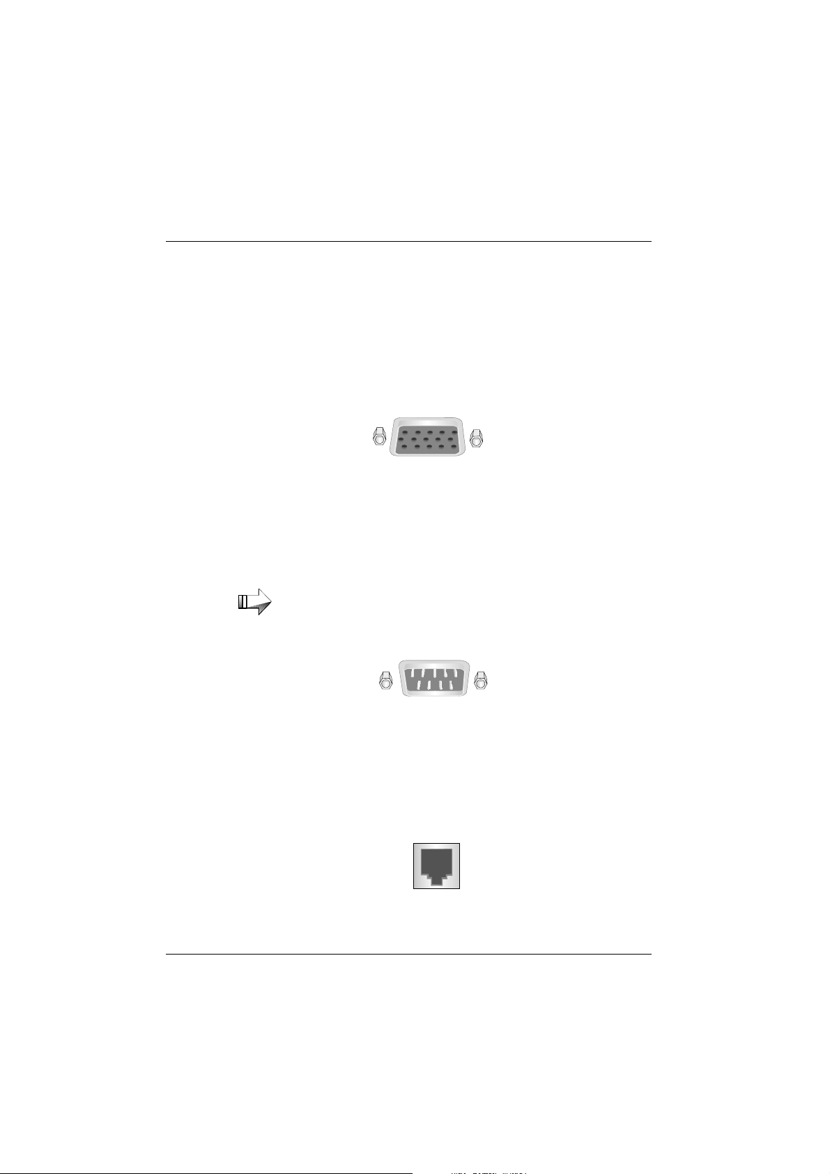
Scanner
Depending on the existing configuration, scanners are connected to the
COM2*, COM3* or COM4* serial interface. This is a 9-pin D-sub socket.
To prevent malfunctioning, make sure that the plug is well secured to the
socket. The scanner can be supplied with power via this socket.
Customer display
An alphanumeric customer display is preferably connected to COM4*.
This is a 9-pin D-sub socket. To prevent malfunctioning, make sure that
the plug is well secured to the socket. Power is supplied via this socket.
Connecting peripherals
Note the maximum current intensity permitted at the COM
interfaces (see “Technical data”).
GB - 19
Connecting peripherals
Monitor
If a SVGA or VGA adapter or SVGA or VGA submodule is installed, you
can connect a monitor to the BEETLE POS system. It is connected to the
system via the 15-pin D-sub socket (SVGA/VGA/LAN/ASYNC) or the sokket of the SVGA/VGA submodule. The monitor is also connected to the
subsocket of the POS system, which supplies it with power.
Standard PC peripherals and scales
Additional standard peripherals are connected to the COM1 serial interface. Scales with their own power supply are also connected to COM1.
If you connect scales to the BEETLE that you have not obtained from WN, you must get an WN license for the driver
software.
Network
GB - 20
If a network adapter is installed or there is a LAN submodule on the rear
panel of the terminal, you can connect the system to a network (LAN). If
there is no LAN connection, there is a cover over the relevant position on
the rear panel (see also the appendix).
Printer (integrated)
Ex works the printer is connected to the COM2* interface and the 24V
supply is used internally.
Printer (LPT1 / V24, 24V, max. 2A)
The standard parallel interface (LPT1)
or the serial interface (V24)
Connecting peripherals
is designed for a printer.
Suitable POS printers connected to the modular version of the
BEETLE /20 can also be supplied with power via a +24V 2A max. low-voltage socket. A connecting cable with a HOSIDEN plug is required for this.
Connect only cable to the 24V connector which are marked
with DP-1 or DP-2.
GB - 21
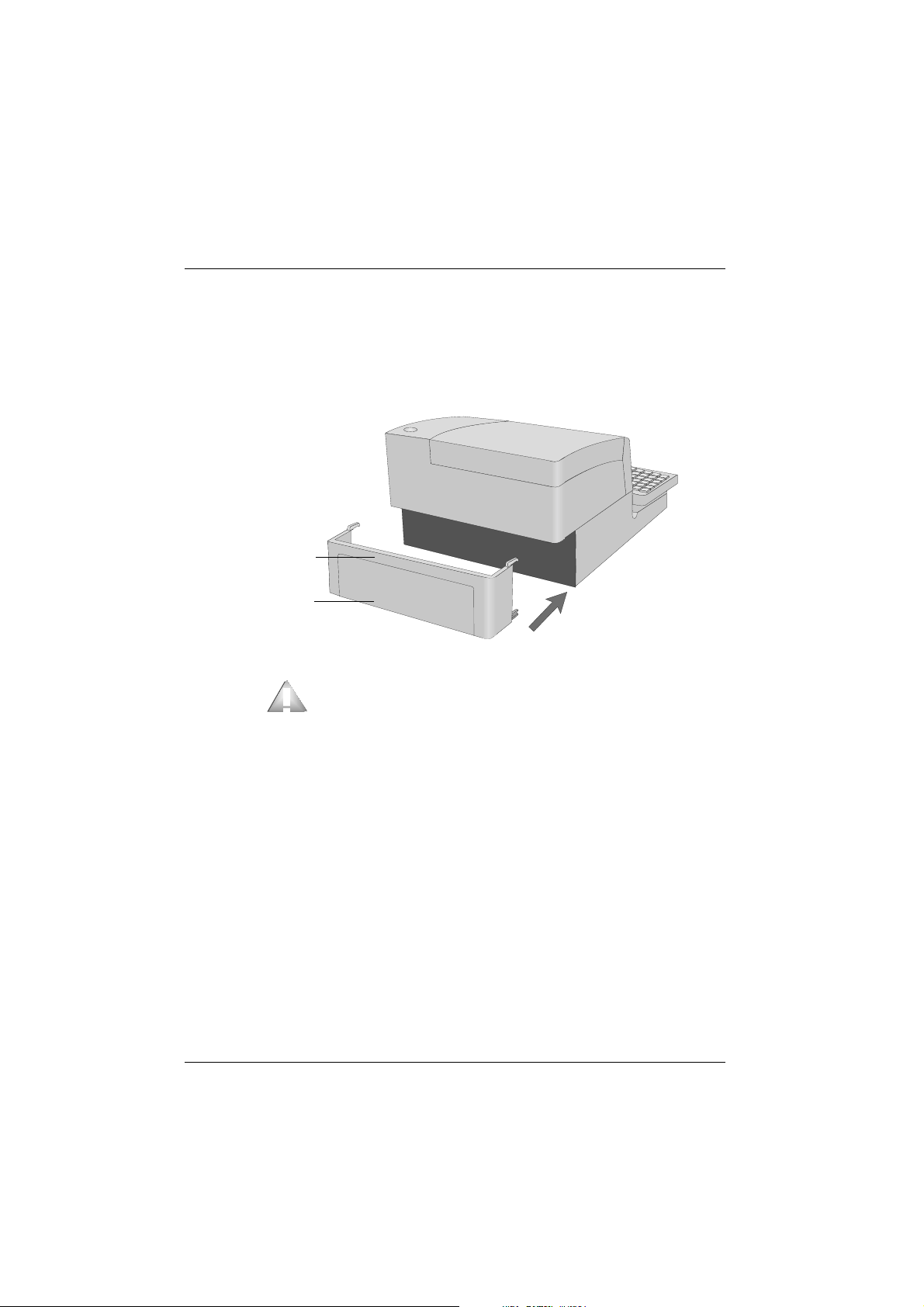
Cable cover
Fixing the cable cover
Fit together part 1 and 2 of the cable cover. Lift the cable from the front
and push it onto the housing.
part 1
part 2
In the case of transporting your BEETLE never take hold of
the cable cover but of the sides.
GB - 22
Cablecover
 Loading...