

Page 1

WPC-651
Single VIA Eden Processor
Micro PC
User’s Manual
P/N: 205-000WPC6510, Version:V1.1
WINCOMM TECHNOLOGY CORP.
Address:3F, No.14 , Prosperity Rd. II, Science-Based Industry Park,
Hsinchu, Taiwan, 300
Tel: +886-3-578-0000
Fax: +886-3-578-0295
Web Site: http://www.wincomm.com.tw/
Copyright© Aug., 2003. All rights reserved
All other brand names are registered trademarks of their respective owners.
Page 2

Copyright Notice
Copyright © 2003 by Wincomm Technology Corp.
All Rights Reserved.
Printed in Taiwan.
This publication is protected by copyright and all rights are reserved. No part or
whole of it may be reproduced or transmitted in any form or by any means,
electronic or mechanical, including photocopying and recording without prior
consent of Wincomm TECHNOLOGY CORP.
The information in this document has been carefully checked and is believed to be
accurate. However, Wincomm TECHNOLOGY CORP. assumes no responsibility
for any errors that may appear in this document. The material contained herein is
for informational purposes only.
The information contained in this document is subject to change without any
notices.
Acknowledgments
All product names or trademarks are properties of their respective owners.
Page 3

III
ΰTo Be Addedα
Page 4

4
Chapter 1 System Overview......................................................... 1-1
1.1 Introduction .............................................................................................1-1
1.2 Features ...................................................................................................1-1
1.3 System Specification ...............................................................................1-3
1.4 System View............................................................................................1-5
1.4.1 Product Outlook ..............................................................1-5
1.4.2 Outline Drawing..............................................................1-7
1.4.3 I/O connectors List..........................................................1-8
1.5 Unpacking ...............................................................................................1-9
Chapter 2 Getting Started............................................................ 2-1
2.1 Setting Up the System .............................................................................2-1
2.2 Using a Compact Flash Memory Card ....................................................2-2
2.3 Using PCMCIA Module ..........................................................................2-4
Chapter 3 BIOS Setup Information............................................ 3-1
3.1 Entering Setup.........................................................................................3-1
3.2 Main Menu ..............................................................................................3-3
3.3 Standard CMOS Setup Menu ..................................................................3-4
3.4 Standard CMOS Setup Menu ..................................................................3-9
3.5 Advanced CMOS Setup Menu ................................................................3-9
3.6 Advanced Chipset Setup Menu .............................................................3-11
3.7 Power Management Setup Menu...........................................................3-14
3.8 PCI/Plug and Play Setup .......................................................................3-15
3.9 Peripheral Setup ....................................................................................3-17
3.10 Hardware Monitor Setup.....................................................................3-20
3.11 BIOS POST Check Point List..............................................................3-20
3.12 Flash BIOS Utility...............................................................................3-25
Page 5

5
J
umper Location................................................................................................
I
Jumper Setting................................................................................................. II
Jumper Notes II
Jumper Setting................................................................................................ III
Connector Definitions ....................................................................................VI
Connectors Location...............................................................................VI
Connectors List..................................................................................... VII
Battery Installation ..............................................................................XIX
Appendix B. System Assembly Reference................................. XXI
Page 6

6
How to Use This Manual
This manual is written for the system integrator, PC technician and
knowledgeable PC end user. It describes how to configure your WPC-651 SERIES
to meet various operating requirements. The user’s manual is divided into four
chapters, with each chapter addressing a basic concept and operation of the server
board.
Chapter 1: Introduction - presents what you have inside the box and gives
you an overview of the product specifications and basic system architecture for
the WPC-651 SERIES Micro PC. And also shows the connectors of WPC-651
so that you can easily configure your system.
Chapter 2: Getting Started - shows you how to set up the system and
introduce how to use PCMCIA and Compact Flash slots.
Chapter 3: BIOS Setup Information - specifies the meaning of each setup
parameter, how to get advanced BIOS performance and update to a new BIOS.
Additionally, the POST checkpoint list will give you a guide for
troubleshooting.
The contents of this manual are subject to change without prior notice. These
changes will be incorporated in new editions of this manual. We may make
supplements or changes for the product described in this manual at any time.
Page 7

1-1
1.1 Introduction
Wincomm’s Micro PC, WPC-651, is especially developed for embedded
application. WPC-651 series are based-on the features of compact size, high
performance, cost-effective and truly low power solution with VIA Eden series
platform. This slim system is ideal used in all harsh environments, such as high
temperature, high pressure or any anxiously for reliable and stable situations but
concern spaces. Surely this compact design is without sacrificing the performance
and functionality.
WPC-651 series can support CRT output as SXGA+, UXGA and UXGA+ for
high resolution. This is very suitable for commercial KIOSK, Point-of-Information
and Point-of-Sales application. Its 10/100 Base-T Ethernet allows the heavy
network assignment in a fast and stable manner.
WPC-651 provides the standard I/O features like the main stream PC
including Compact Flash Interface, two serial ports, one parallel port, two USB
ports, audio ports for line-in/line-out/mic-in, one PS/2 port to support Mouse and
Keyboard via Y-cable, Reset/Power-on switch and Power-on/HDD/LAN
indicators.
WPC-651 provides one PCMCIA interface for 16-bit PCMCIA module or
ATA flash memory module. This feature can support some application such as
Wireless LAN, GPS and so on.
WPC-651 series are rugged with aluminum-packed chassis, and the compact
size for 170x150x66mm is easy to develop for various appliances, such as
information collecting machine in Factory Automation, home-PC, mobile
application, medical facilities and any other computing equipment in today’s
unrestrained technical field.
1.2 Features
The WPC-651 features:
Page 8

1-2
VIA Ed
en
400MHz (WPC-651-P400
series) w
ith int
ernal
FANLESS
thermal solution
VIA C3 Low Voltage 1GHz (WPC-651-P1000 series) with
Wincomm’s proprietary thermal solution
System Memory
128/256 MB system RAM, maximum to 512 MB
Mass Storage Device
One 2.5-inch IDE hard disk drive
Compact Flash Memory Support
One Compact Flash slot, support Compact Flash memory card
PCMCIA interface
One PCMCIA slot, support 16-bit PCMCIA module and ATA flash
memory module with hot-swapping function
Video Function
VGA display controller with AGP4X enhanced 2D and 3D graphics,
display memory dynamic sharing with system memory (up to 32MB)
Audio Function
Dual full-duplex Direct Sound channel between system memory and
AC97 link, standard AC97 codec interface with Line-in, Line-out and
Microphone-in ports
Ethernet Function
10/100Base-T Ethernet bus
Page 9

1-3
AMI BIOS, 2 MB Flash EEPROM, Pl
ug-and-Play compa
tibl
e
Watchdog Function
1~63 seconds, software programmable
1.3 System Specification
NOTE: Specifications are subject to change without notice.
Parts Specifications
CPU
VIA Eden 400MHz processor onboard or VIA C3
Low Voltage 1GHz processor onboard
Other VIA EBGA-type processors can be requested
by OEM model
System
memory
144-pin DIMM socket supporting PC100/133
64/128/256/512 MB SDRAM
CPU Board:
WEB-6580
I/O
interfaces
CRT port
RS-232C port (COM1)
RS-232C/422/485 port (COM2)
SPP/EPP/ECP parallel port
PS/2 keyboard/mouse port
10/100 Base-T LAN connector
Compact Flash Interface
PCMCIA
Slot:
WTB-PCMCI
A
PC-104
Peripheral
module
Comply with PCMCIA V.2.10 and JEIDA 4.1
specification
Support each slot accept type II card
16-bit data bus
Support Read/Write Flash card with Hot-swapping
function
USB and
Audio
Connectors:
WTB-A01
Peripheral
module
Two USB 1.1 ports
Microphone input connector
Line input connector
Line output connector
Page 10
1-4
Output
power
60W
AC-to-DC
Power
Adapter
Input
voltage
100 a 240 V, 47~63 Hz, 1.9A
Power
Output
voltage
Output Maximum Load
+5 V 7 A
+12 V 3 A
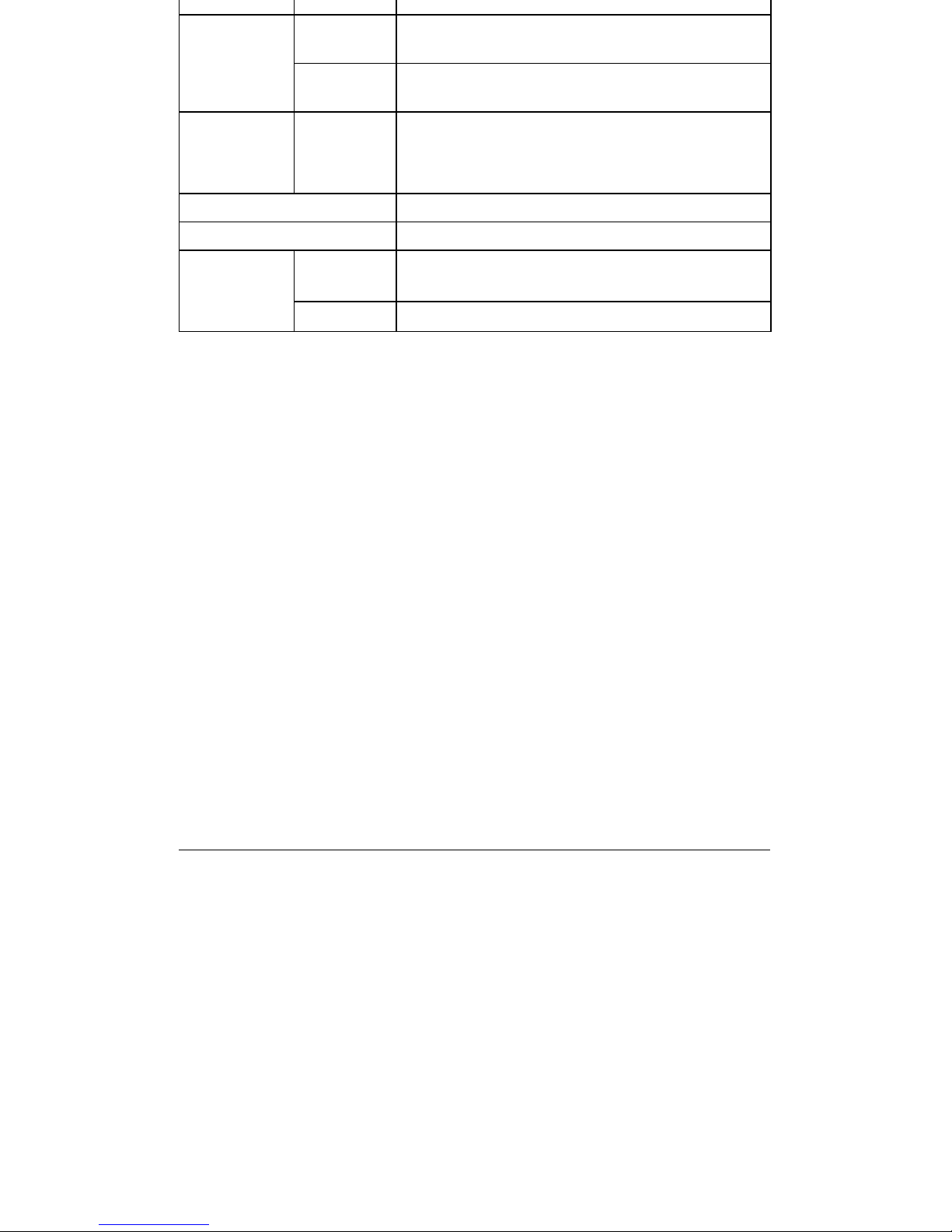
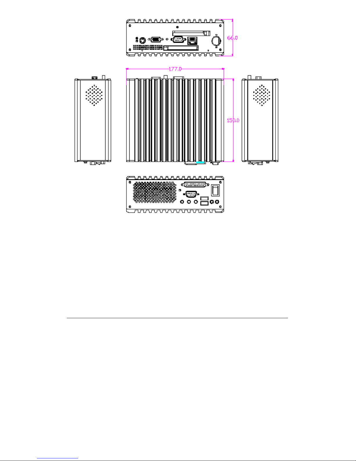
Dimension 170×150×66 mm (LxWxH)
Weight 3.0 Kg (net), 4.5Kg (gross)
Temperature
Operating: 0 qC a 40 qC
Storage: –20 qC a 60 qC
Environment
Humidity
5% a 90% @ RH, non-condensing
Page 11
1-5
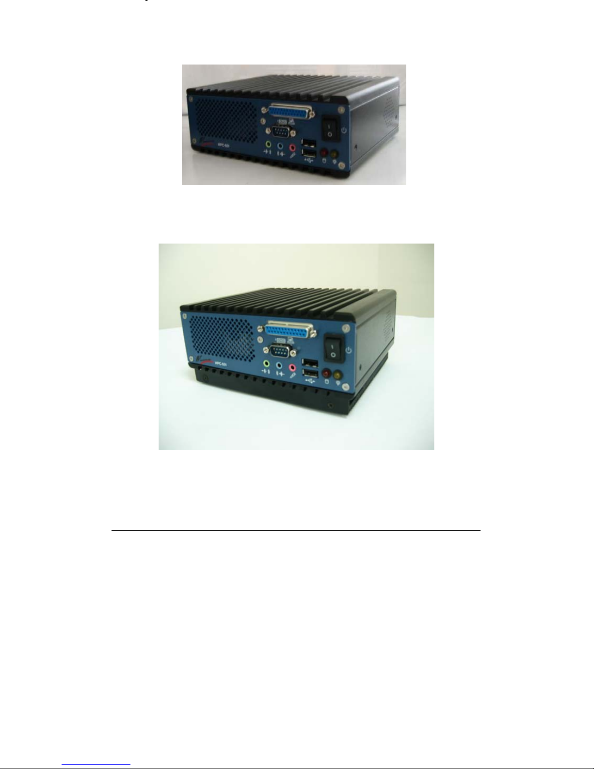
1.4.1 Product Outlook
The front view of WPC-651-P400
The front view of WPC-651-P1000
Page 12
1-6
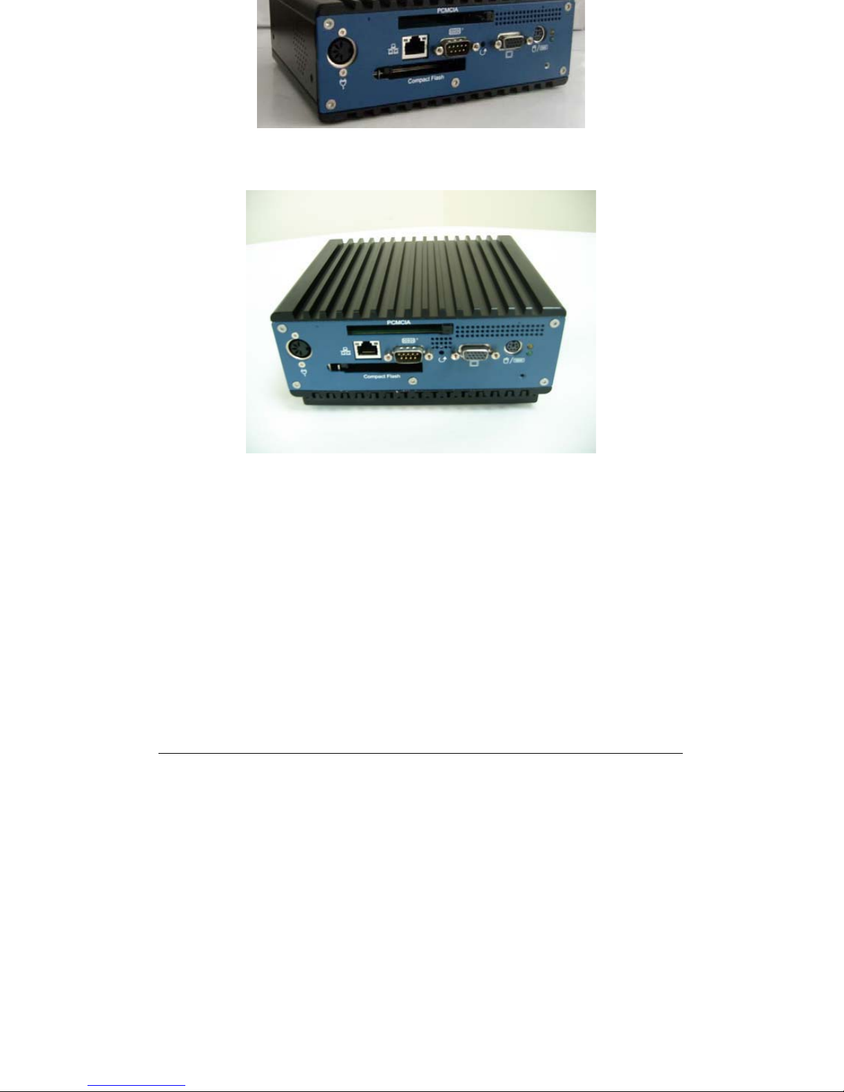
The rear view of WPC-651-P400
The rear view of WPC-651-P400
Page 13
1-7
Page 14
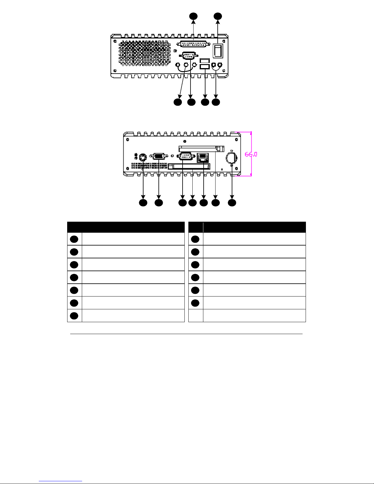
1-8
˄ ˅ ˆ ˇ
ˈ
Front Panel
ˉ
ˌˋˊ ˄˃
Rear Panel
˄˄ ˄˅ ˄ˆ
Ref Component Ref Component
Audio for Line-in, Line-out, Mic-in CRT output
Serial port for RS-232 Serial port for RS-232/422/485
USB 1.1 ports Compact Flash slot
Power-on and HDD LEDs RJ45 for Ethernet
LPT port PCMCIA slot
Power-on Switch DC-in for power input
PS/2 Keyboard and Mouse
˄ ˋ
˅ ˌ
ˆ ˄˃
ˇ ˄˄
ˈ ˄˅
ˉ ˄ˆ
ˊ
Page 15

1-9
After unpacking the shipping carton, you should find these standard items:
The WPC-651 Micro PC
Accessory box:
– Power cord cable
– AC-DC Adapter
– Y-cable for PS/2 Keyboard and Mouse
– System Driver, Utility and User Manual CD-title
– Quick installation Guide
– Fixed Brackets
Inspect all the items. If any item is damaged or missing, notify your dealer
immediately.
Page 16

2-1
This chapter tells you how to set up the system.
2.1 Setting Up the System
The following is a summary of the steps in setting up the system for use.
CAUTION: Make sure that power to the system and each of the devices to be
connected is switched OFF before plugging in the connectors.
1. Make any required external connections such as the display, keyboard, and
mouse.
2. Plug the appropriate end of the power cord into the power connector of
AC-to-DC Adapter and plug the other end-side to DC Power-in connector of
the on the rear of the system. Then plug the other end of the power cord to an
electrical outlet.
3. Press the power switch on the front of the system to turn on the system’s
power.
4. If necessary, run the BIOS SETUP program to configure the system (see
Chapter 3).
5. Install the software drivers if necessary.
Page 17
2-2
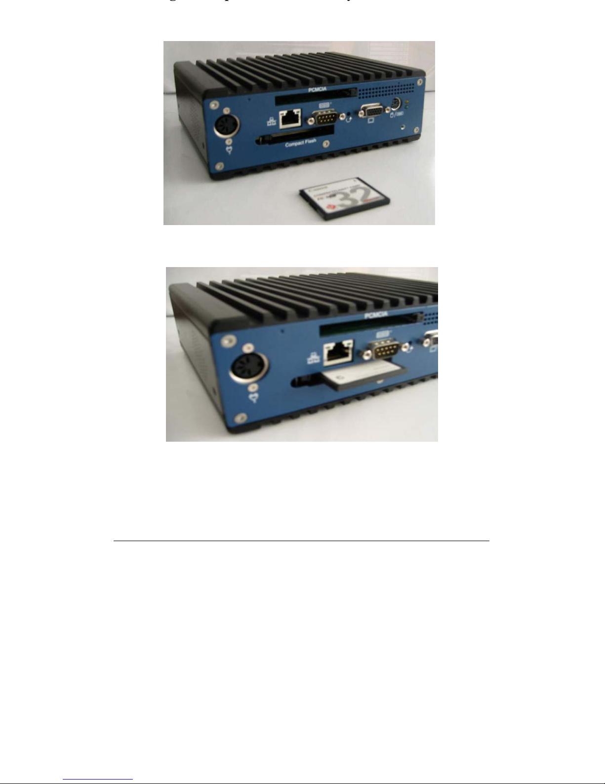
To insert a Compact Flash Memory Card, please follow the blowing steps.
1. Locate the Compact Flash Memory Card slot on the rear of the system.
2. Slide the Compact Flash Memory Card into the slot until the eject button
pops out and push the eject button to the left side until closed to the stick.
Page 18
2-3
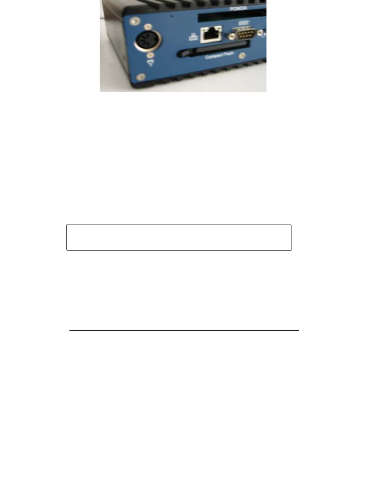
3. When a new card is seated, the system may detect it and try to install the
appropriate driver. Follow the onscreen instruction to complete the
process.
To remove a Compact Flash Memory Card:
1. Please turn off the system before you remove the Compact Flash Memory
Card.
2. Move the eject button from the stick.
3. Push the eject button and the card will slide out slightly.
4. Pull the card out of the slot.
Note:
Not support hot swap mode. Please turn off the system while you plug or
remove the compact flash module.
Page 19
2-4
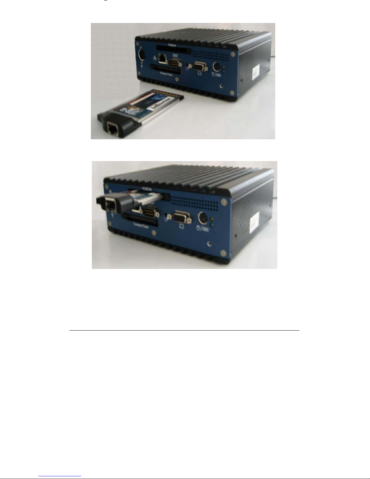
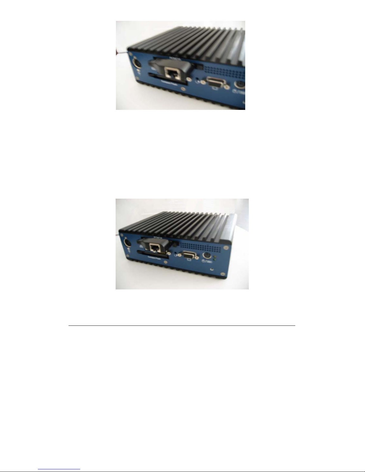
To insert a PCMCIA module, please follow the blowing steps.
1. Locate the Compact Flash Memory Card slot on the rear of the system.
Page 20
2-5
2. Slide the PCMCIA module into the slot until to the bottom of the slot.
3. When a new card is seated, the system may detect it and try to install the
appropriate driver. Follow the onscreen instruction to complete the
process.
To remove the PCMCIA module,
1. Please push the button on the right side of the slot and the button will be
pop-up.
2. Pull the card out of the slot.
Page 21

3-1
WPC-651 is equipped with the AMI BIOS stored in Flash ROM. The BIOS
has a built-in Setup program that allows users to modify the basic system
configuration easily. This type of information is stored in CMOS RAM so that it is
retained during power-off periods. When system is turned on, WPC-651
communicates with peripheral devices and check its hardware resources against the
configuration information stored in the CMOS memory. If any error is detected, or
the CMOS parameters need to be initially defined, the diagnostic program will
prompt the user to enter the SETUP program. Some errors are significant enough to
abort the start-up.
3.1 Entering Setup
Turn on or reboot the computer. When the message “Hit <DEL> if you want to
run SETUP” appears, press <Del> key immediately to enter BIOS setup program.
If the message disappears before you respond, but you still wish to enter Setup,
please restart the system to try “COLD START” again by turning it OFF and then
ON, or touch the "RESET" button. You may also restart from “WARM START” by
pressing <Ctrl>, <Alt>, and <Delete> keys simultaneously. If you do not press the
keys at the right time and the system will not boot, an error message will be
displayed and you will again be asked to,
Press <F1> to Run SETUP or Resume
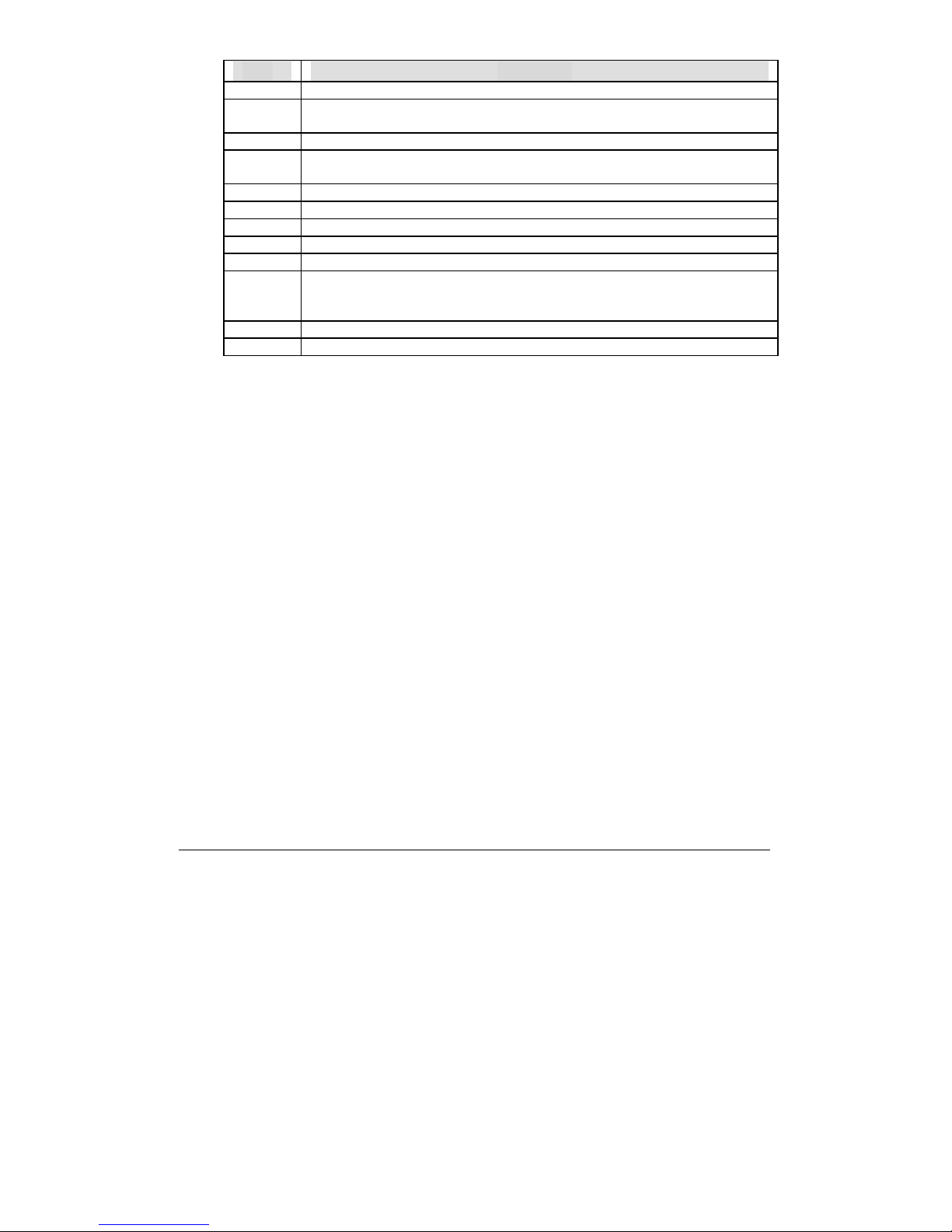
In HIFLEX BIOS setup, you can use the keyboard to choose among options
or modify the system parameters to match the options with your system. The table
below will show you all of keystroke functions in BIOS setup.
Page 22
3-2
Keys to navigate within setup menu
Key Functions
Up Arrow Move to the previous ite
m
Down
Arrow
M
ove to the next ite
m
Left Arrow Move to the item on the left (menu bar)
Right
Arrow
M
ove to the item on the right (menu bar)
Move Enter Move to the item you desired
P
ageUp key Increase the numeric value or make changes
P
ageDn key Decrease the numeric value or make changes
+ key Increase the numeric value or make changes
- key
D
ecrease the numeric value or make changes
Esc key Main Menu -- Quit and not save changes into CMOS
Status Page Setup Menu and Option Page Setup Menu -- Exit current page and
r
eturn to Main Menu
F1 key General help on Setup navigation keys
F10 key Save all the CMOS changes and exit
Page 23

3-3
3.2 Main Menu
Once you enter WPC-651 AMI BIOS CMOS Setup Utility, you should start
with the Main Menu. The Main Menu allows you to select from eleven setup
functions and two exit choices. Use arrow keys to switch among items and press
<Enter> key to accept or bring up the sub-menu.
AMIBIOS HIFLEX SETUP UTILITY – VERSION 1.30
Standard CMOS Setup
Advanced BIOS Setup
Advanced Chipset Setup
Power Management Setup
PCI / Plug and Play Setup
Peripheral Setup
Hardware Monitor Setup
Auto-Detect Hard Disks
Change User Password
Change Supervisor Password
Auto Configuration with Optimal Settings
Auto Configuration with Fail Safe Settings
Save Settings and Exit
Exit Without Saving
Standard CMOS Setup for changing time, date, hard disk type, etc.
NOTE: It is strongly recommended to reload Optimal Setting if CMOS is lost or
BIOS is updated.
Page 24
3-4
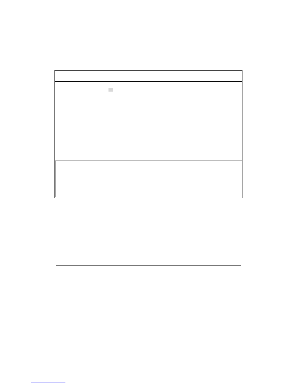
This setup page includes all the items in a standard compatible BIOS. Use the
arrow keys to highlight the item and then use the <PageUp>/<PageDn> or <+>/<->
keys to select the value or number you want in each item and press <Enter> key to
certify it.
Follow command keys in CMOS Setup table to change Date, Time, Drive type,
and Boot Sector Virus Protection Status.
Screen shot
AMIBIOS SETUP – STANDARD CMOS SETUP
(C)2000 America Megatrends, Inc. All Rights Reserved
Date (mm/ dd/yyyy): Mon, Oct 2 1999
Time (hh/mm/ss): 16:51:13
Floppy Drive A: 1.44 MB 3 1/2
Floppy Drive B: Not Installed
Base Memory: 640 KB
Extd Memory: 119 KB
LBA Blk PIO 32Bit
Type Size Cyln Head WPcom Sec Mode Mode Mode Mode
Pri Master Auto On
Pri Slave Auto On
Sec Master Auto On
Sec Slave Auto On
Boot Sector Virus Protection Disabled
Month: Jan – Dec ESC : Exit ХЦ:Sel
Day: 01 – 31 PageUp/PageDn : Mofify
Year: 1901 – 2099 F1:Help F2/F3:color
Page 25
3-5
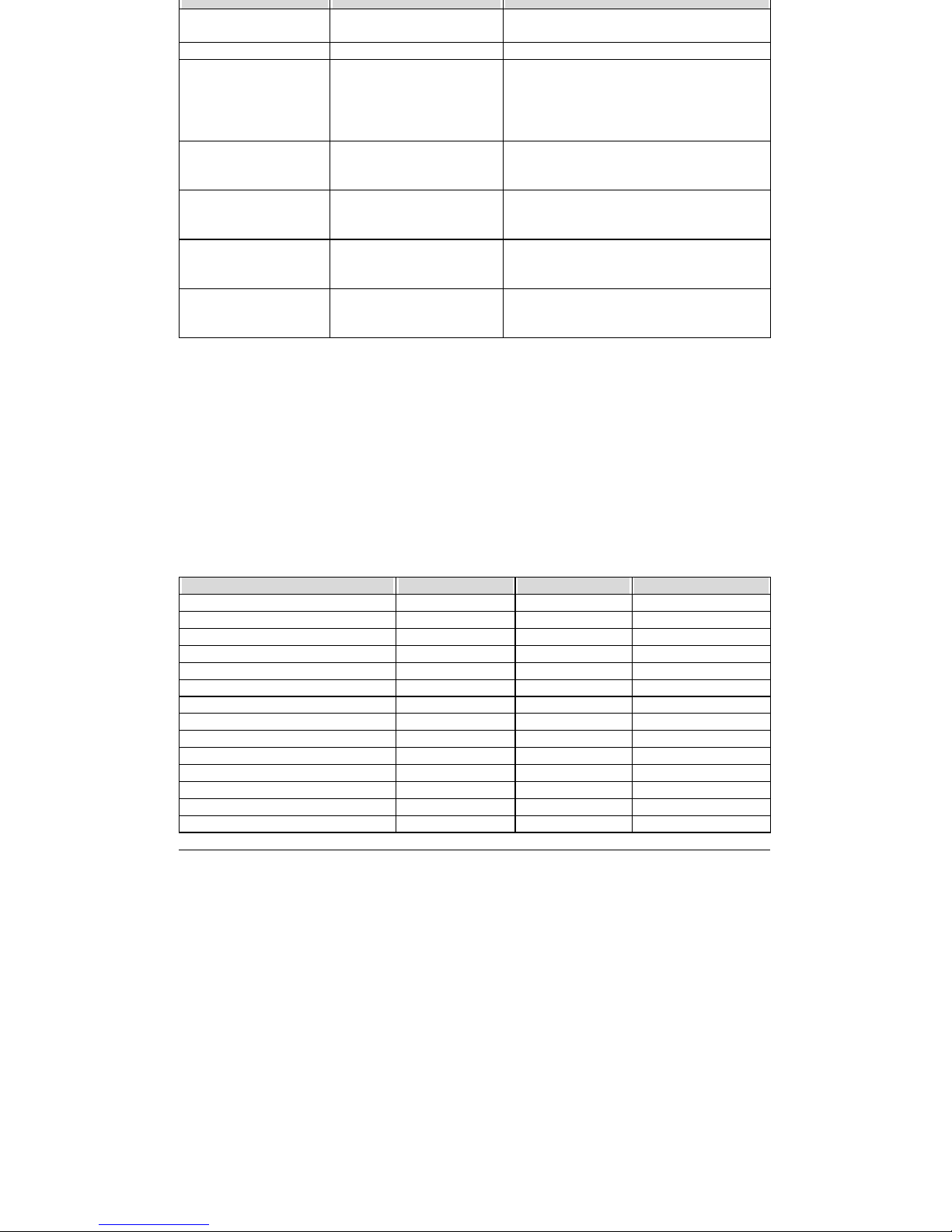
Item Options Description
Date Mm:dd:yy Set the system date. Note that the ‘Day’
automatically changes when you set the date
Time Hh:mm:ss Set the system time
Drive A
Drive B
Non Installed
360KB, 5 1/4
1.2MB, 5 1/4
720KB, 3 1/2
1.44MB, 3 1/2
Select the type of floppy disk drive
installed in your system
Pri Master Select a suitable item or
keep it in Auto for automatic
detection.
Press <PageUp> or <PageDn> to select a
suitable item
Pri Slave Select a suitable item or
keep it in Auto for automatic
detection.
Press <PageUp> or <PageDn> to select a
suitable item
Sec Master Select a suitable item or
keep it in Auto for automatic
detection.
Press <PageUp> or <PageDn> to select a
suitable item
Sec Slave Select a suitable item or
keep it in Auto for automatic
detection.
Press <PageUp> or <PageDn> to select a
suitable item
Advanced CMOS Setup
This setup reference table includes all the Optimal, Failsafe, and Other options
setting in each BIOS setup item. It is very easy to cross reference. If you want to go
details, you can directly refer to item description in sub-section.
ADVANCED CMOS SETUP DEFAULTS
BIOS Setup Items Optimal Default Failsafe Default Other Options
Quick Boot Enabled Disabled
1st Boot Device Floppy Floppy
2nd Boot Device IDE-0 IDE-0
3rd Boot Device CDROM CDROM
Try Other Boot Device Yes Yes No
S.M.A.R.T. for Hard Disks Disabled Disabled Enabled
Boot Up Num-Lock On On Off
Floppy Drive Swap Disabled Disabled Enabled
Floppy Drive Seek Disabled Disabled Enabled
PS/2 Mouse Support Enabled Enabled Disabled
System Keyboard Absent Absent Present
Primary Display Absent Absent VGA/EGA,…,Mono
Password Check Setup Setup Always
Boot To OS/2 No No Yes
Page 26
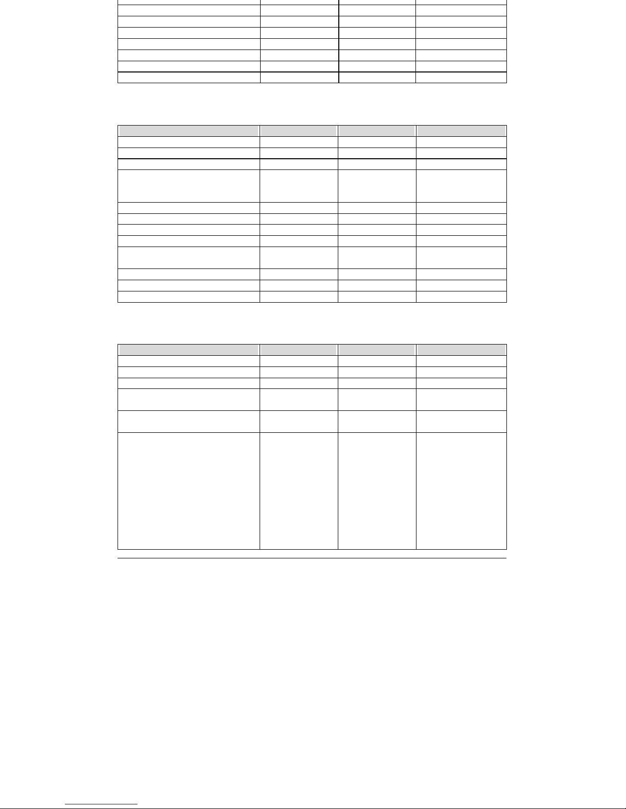
3-6
System BIOS Cacheable
Enabled
Disabled
C000, 32K Shadow Cached Cached Enabled, Disabled
C800, 16K Shadow Cached Cached Enabled, Disabled
CC00, 16K Shadow Cached Cached Enabled, Disabled
D000, 16K Shadow Disabled Disabled Cached, Enabled
D400, 16K Shadow Disabled Disabled Cached, Enabled
D800, 16K Shadow Disabled Disabled Cached, Enabled
DC00, 16K Shadow Disabled Disabled Cached, Enabled
ADVANCED CHIPSET SETUP
BIOS Setup Items Optimal Default Failsafe Default Other Options
Configure SDRAM Timing by SPD Disabled Disabled Enabled
DRAM Frequency 100Mhz 100Mhz 133Mhz ,66Mhz
SDRAM CAS# Latency 3 3 2
Memory Hole Disabled Disabled 512KB-640KB,
15MB-16MB,
14MB-16MB
AGP Mode 4x 2x 1x
AGP Aperture Size 64MB 64MB 4,8,16,32,128,256MB
Search for DMA Resources Yes No
PCI Delay Transaction Enabled Disabled
USB Controller All USB Port Disabled USB Port 0&1, USB
Port 2&3.
USB KB/Mouse Legacy Support Disabled Disabled No mice,All Device
Spread Spectrum Controller Normal Normal Enable
Spread Spectrum Controller 0.25% 0.25% 0.5%
POWER MANAGEMENT SETUP DEFAULTS
BIOS Setup Items Optimal Default Failsafe Default Other Options
Power Management / APM Enabled Disabled
Video Power Down Mode Disabled Disabled Stand By, Suspend
Hard Disk Power Down Mode Disabled Disabled Stand By, Suspend
Standby Time Out (Minute) Disabled Disabled 1, 2, 4, 8, 10, 20, 30,
40, 50, 60 .
Suspend Time Out (Minute) Disabled Disabled 1, 2, 4, 8, 10, 20, 30,
40, 50, 60 .
Throttle Slow Clock Ratio 50 %-56.25% 50 %-56.25% 0%-6.25%,
6.25%-12.5%,
18.75%-25%,
31.25%- 37.5%,
37.5%-43.75%
43.75%-50%
56.25%-62.5%
62.5%-68.75%
68.75%-75%
75%-87.5%
75%-81.25%
Page 27
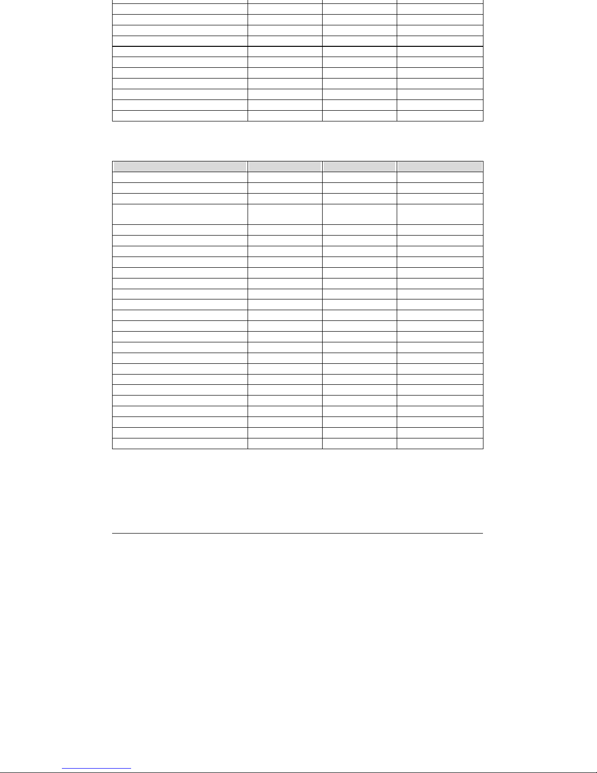
3-7
93.75% 100%
Display Activity Ignore Ignore Monitor
IRQ3 Monitor Ignore Ignore
IRQ4 Monitor Ignore Ignore
IRQ5 Ignore Ignore Monitor
IRQ7 Monitor Ignore Ignore
IRQ9 Ignore Ignore Monitor
IRQ10 Ignore Ignore Monitor
IRQ11 Ignore Ignore Monitor
IRQ13 Ignore Ignore Monitor
IRQ14 Monitor Ignore Ignore
IRQ15 Ignore Ignore Monitor
PCI / Plug AND Play SETUP
BIOS Setup Items Optimal Default Failsafe Default Other Options
Plug and Play Aware O/S No No Yes
Clear NVRAM No No Yes
On Chip VGA Fram Buffer Size 8MB 8MB None,2,4,16.32MB
PCI Latency Timer (PCI Clocks) 32 32 32, 96, 128, 160, 192,
224, 248
Boot Screen Select Auto Auto Both CRT & LCD,
LCD Panel Type 0 0 1 ~ 15
PCI VGA Palette Snoop Disabled Disabled Enabled
Allocate IRQ to PCI VGA Yes Yes No
PCI IDE Bus Master Disabled Disabled Enabled
DMA Channel 0 PnP PnP ISA/ EISA
DMA Channel 1 PnP PnP ISA/ EISA
DMA Channel 3 PnP PnP ISA/ EISA
DMA Channel 5 PnP PnP ISA/ EISA
DMA Channel 6 PnP PnP ISA/ EISA
DMA Channel 7 PnP PnP ISA/ EISA
IRQ3 PCI/ PnP PCI/ PnP ISA/ EISA
IRQ4 PCI/ PnP PCI/ PnP ISA/ EISA
IRQ5 PCI/ PnP PCI/ PnP ISA/ EISA
IRQ7 PCI/ PnP PCI/ PnP ISA/ EISA
IRQ9 PCI/ PnP PCI/ PnP ISA/ EISA
IRQ10 PCI/ PnP PCI/ PnP ISA/ EISA
IRQ11 PCI/ PnP PCI/ PnP ISA/ EISA
IRQ12 PCI/ PnP PCI/ PnP ISA/ EISA
IRQ14 PCI/ PnP PCI/ PnP ISA/ EISA
IRQ15 PCI/ PnP PCI/ PnP ISA/ EISA
Page 28
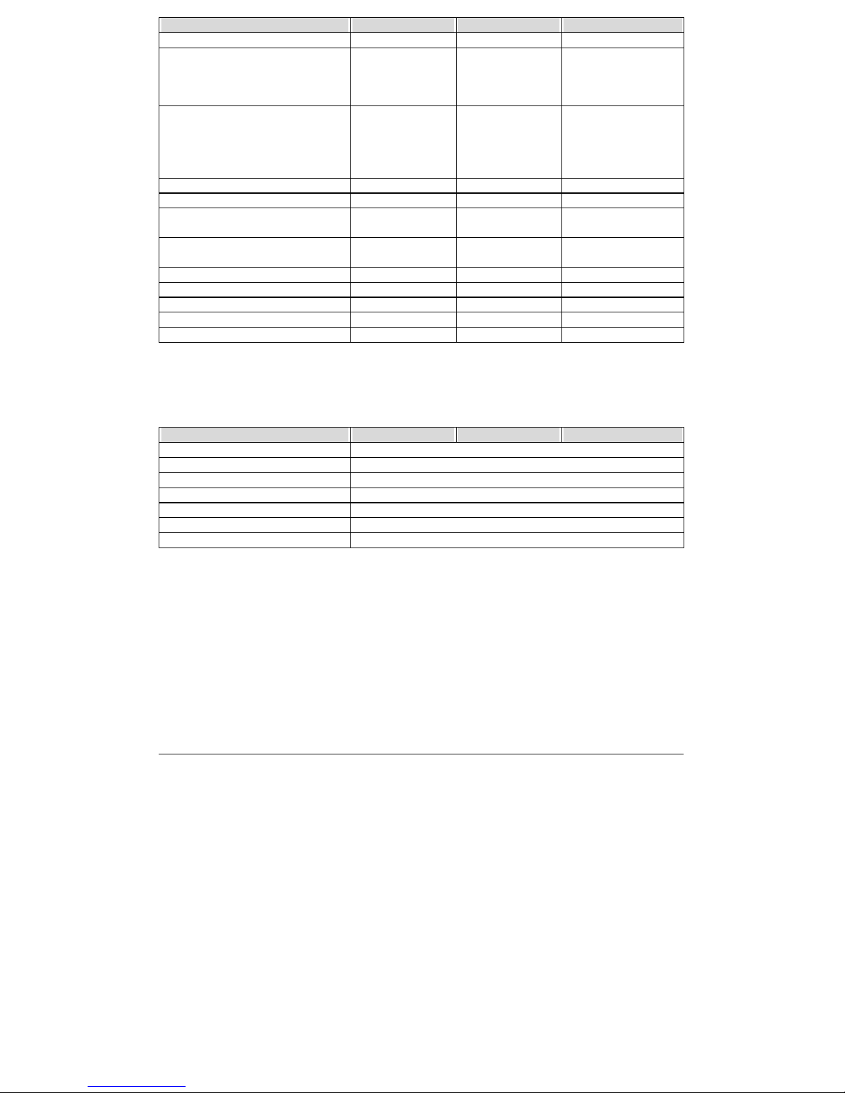
3-8
PERIPHERAL SETUP DEFAULTS
BIOS Setup Items Optimal Default Failsafe Default Other Options
On Board FDC Auto Auto Enabled, Disabled
On Board Serial Port1 3F8/COM1 3F8/COM1 Disabled 3F8h/COM1,
2F8h/COM2,
3E8h/COM3,
2E8h/COM4,
On Board Serial Port2 2F8/COM2 2F8/COM2 Disabled
3F8h/COM1,
2F8h/COM2,
3E8h/COM3,
2E8h/COM4,
Serial Port2 Mode Normal Normal IrDA, ASK IR
Duplex Mode N/A N/A
On Board Parallel Port 378 378 Disabled, 378, 278,
3BC
Parallel Port Mode Normal Normal Normal, EPP, ECP,
EPP+ECP
EPP Version N/A N/A
Parallel Port DMA Channel N/A N/A
Parallel Port IRQ 77 5
On Board IDE Both N/A Auto
Onboard AC’ 97 Audio Enabled Enabled Disabled
HARDWARE MONITOR SETUP DEFAULTS
BIOS Setup Items Optimal Default Failsafe Default Other Options
System Temperature ===
CPU Fan Speed ===
Vcore ===
+ 2.500V ===
+ 3.300V ===
+ 5.000V ===
+ 12.000V ===
Page 29

3-9
This setup page includes all the items in a standard compatible BIOS. Use the
arrow keys to highlight the item and then use the <PageUp>/<PageDn> or <+>/<->
keys to select the value or number you want in each item and press <Enter> key to
certify it.
Follow command keys in CMOS Setup table to change Date, Time, Drive type,
and Boot Sector Virus Protection Status.
3.5 Advanced CMOS Setup Menu
This setup includes all of the advanced features in the system. The detail
descriptions are specified as below.
Quick Boot
Set “Disabled” for normal booting or select “Enabled” to skip minor BIOS
test items to obtain quick boot response.
Boot Up Sequence
This category includes six items to determine which drive computer
searches first for the Disk Operating System (DOS).
The default ARMD (ATAPI Removable Media Device) emulation type is set
to popular drive type LS-120 and ATAPI ZIP. There are many choices of
booting devices to boot up system. User can select “Disabled”, “IDE-0”,
“IDE-1”, “IDE-2”, “IDE-3”, “Floppy”, “ARMD-FDD”, “ARMD-HDD”,
“CDROM”, “SCSI”, or “NETWORK”.
Try Other Boot Device
Select “Yes” to enable trying to boot from different devices in sequence.
Selected “No” for booting only from the first boot device.
Page 30

3-10
Self-Monitoring, analysis and reporting Technology. For prediction of
device degradation and/or faults.
Boot Up Num-Lock
Select “On” to enable numeric function of the numeric keypad, or “Off” to
disregard it.
PS/2 Mouse Support
Select “Enabled” to enable PS/2 mouse function, or “Disabled” to release
IRQ12 interrupt for other ISA-bus I/O devices.
System Keyboard
This option will be used to neglect “keyboard error” while you choose
Absent setting in your BIOS setup and system has no keyboard attached.
Primary Display
Chooses Absent, VGA/EGA, CGA40x25, CGA80x25, or Mono to meet
your monitor type. If you select Absent, the “CMOS Display Type Wrong”
message will be ignored regardless the mismatched display card.
Password Check
This option enables the password checking when the system boots up or runs
CMOS Setup. It only takes effect after setting Change Supervisor Password.
Setup : This option will force system to check password before running
Setup if you have already entered the current user password in “Change User
Password”. By that time, the system will be only able to boot but deny
accessing Setup.
Page 31

3-11
CMOS or try to reload BIOS Setup to boot up system.
Boot To OS/2
You should set this option to “Yes” to support OS/2 environment.
L1 Cache
This option controls to turn on or off the CPU’s Level 1 built-in cache.
L2 Cache
Enables this option to turn on or off the CPU’s Level 2 built-in cache.
System BIOS Cacheable
Enables this option to enhance system performance by shadowing and
caching system BIOS. When disabled, this BIOS shadow function will be
ignored.
Shadow Memory
Each of segments provides three options “Disabled”, “Enabled”, and
“Cached” for faster adapter’s ROM execution. However this shadow
function is Chipset oriented and dependent on system hardware feature. In
general, C000 64k will be allocated for VGA BIOS and set to Cached to get
higher display performance by shadowing and caching feature. If user
chooses Enabled setting, only BIOS shadow function is active.
3.6 Advanced Chipset Setup Menu
This setup is very important to keep system stability. If you are not technical
Page 32

3-12
Configre SDRAM Timing by SPD
This option provides DIMM plug-and-play support by Serial Presence
Detect (SPD) mechanism via the System Management Bus (SMBus)
interface. You can disable this option to manage the following four SDRAM
timing options by yourself. In addition, SDRAM operating timings may
follow serial presence from EEPROM content by setting this option to
“Enabled”, and all of SDRAM timing options will be not available and
hidden.
DRAM Frequency
PC-100 means the memory bus is running at 100MHz. PC-133 means its bus
is running at 133MHz.
SDRAM CAS# Latency
This option controls the number of SCLKs between the time a read
command is sampled by the SDRAMs and the time the North Bridge, 8601A,
samples correspondent data from the SDRAMs.
Spread Spectrum
This option is for EMI test only.
Memory Hole
This option allows the end user to specify the location of a memory hole for
memory space requirement from ISA-bus cards.
USB Controller
This option will enable on-chip USB function to support USB peripheral
Page 33

3-13
USB KB/Mouse Legacy Support
This feature will be automatically disabled and hidden if user chooses the
“Disabled” setting from the foregoing USB Function option. Otherwise,
enabling this option provides support for USB-keyboard without auxiliary
driver under DOS environment.
Page 34

3-14
This APM (Advanced Power Management) determines how much power
energy can be saved by setting below items to handle system power resource. The
following descriptions will specify the definition of each item in details.
Power Management/APM
Using this feature to control system power resources. Set this option to
“Enabled” to enable power management function and effective based on
following parameter settings.
Video Power Down Mode
This option specifies the power conserving state that the VESA VGA video
subsystem enters after the specified period of display inactivity has expired.
Hard Disk Power Down Mode
This option specifies the power management state that the HDD enters after
the specified period of hard drive inactivity has expired. It is the same as
video power control. If user chooses “Stand By” or “Suspend”, it will
depend on period of parameter “Stand By Time out” or “Suspend Time out”.
Stand by Time out (Minute)
This option specifies the length of the period of system inactivity while the
computer is in Full-On power state before the computer is placed in Standby
mode. When this length of time expires, the computer enters Standby
Timeout state. In Standby mode, some power use is curtailed.
Suspend Time out (Minute)
This option is the same as Stand by Time out function. These two features
will be enabled to monitor power of sub-items “Display Activity”, “Serial
port”, “Parallel Port”, “Floppy”, “Pri-HDD”, and “Sec-HDD” independently.
It is also used to control CPU throttle running function. All of sub-items will
be ineffective in selection of disabling “Stand by Time out” or “Suspend
Time out” even if it can be choose by user in BIOS setup menu.
Throttle Slow Clock Ratio
Page 35

3-15
signal. This duty cycle indicates the percentage of time the STPCLK# signal
is asserted while in the throttle mode.
Display Activity
This option specifies if BIOS is to monitor activity on the display monitor
for power conservation purposes. If set to Monitor and the computer is in a
power saving state, BIOS watches for video display activity. The computer
enters the full on power state if any activity occurs. BIOS reloads the
Standby and Suspend timeout timers if activity occurs on the specified IRQ
lines. If you set to Ignore, video display monitor activity is not monitored.
IRQ Active
When set to Monitor, these options enable event monitoring on the specified
IRQ. If set to Monitor and the computer is in a power saving state, BIOS
watches for activity on the device with specified IRQ line. The computer
enters the full on power state if any activity occurs. BIOS reloads the
Standby and Suspend timeout timers if activity occurs on the specified IRQ.
No monitoring activity occurs if the option is set to Ignore. The settings for
each of these options are Monitor or Ignore.
3.8 PCI/Plug and Play Setup
This section describes configuring the PCI bus system. PCI (Peripheral
Component Interconnect) is a system that allows I/O devices to operate at speeds
nearing CPU’s when they communicate with own special components.
All of options described in this section are important and technical and it is
strongly recommended that only experienced users could make any changes to the
default settings.
Plug and Play Aware O/S
Set this option to “Yes” if the operating system installed in the computer is
Plug and Play-aware. The BIOS only detects and enables PnP ISA adapter
cards that are required for system boot. The Windows 95 operating system
detects and enables all other PnP-aware adapter cards. Windows 95 is
Page 36

3-16
PnP-aware adapter cards installed in your computer will not be configured
properly.
Clear NVRAM
This option is used to clear NVRAM and check or update ESCD (Extended
System Configuration Data) data after system power on. Set this option to
No that will not clear NVRAM and the operation of update ESCD is
effective in different ESCD data comparison. If you select the “Yes” setting,
then the BIOS will update ESCD each time of power on.
PCI Latency Timer (PCI Clocks)
This option is used to control PCI latency timer period (follow PCI clocks).
Based on PCI specification 2.1 or later and PCI bus frequency in system,
user can select different timer to meet their PCI bus environment.
PCI VGA Palette Snoop
Some display cards that are non-standard VGA such as graphics
accelerations or MPEG video cards may not show colors properly. User can
choose “Enabled” setting to correct this display mismatch problem and
support any ISA adapter card installed in the computer requires VGA palette
snooping.
Allocate IRQ to PCI VGA
This option will be used to allocate IRQ for PCI VGA card. In general, some
of PCI VGA cards need IRQ support.
PCI IDE Bus Master
Set this option to Enabled to specify that the IDE controller on the PCI local
bus has bus mastering capability.
DMA Channel 0/1/3/5/6/7
These options specify if the named DMA channel is available for using on
the ISA/EISA bus or PnP (Plug & Play).
IRQ 3/4/5/7/9/10/11/12/14/15
Page 37

3-17
adapter cards. These options determine if AMIBIOS should remove an IRQ
from the pool of available IRQs passed to devices that are configurable by
the system BIOS. The available IRQ pool is determined by reading the
ESCD NVRAM. If more IRQs must be removed from the pool, the end user
can use these PCI/PnP Setup to remove the IRQ by assigning the option to
the ISA/EISA setting. All IRQs used by on-board I/O are configured as
PCI/PnP.
3.9 Peripheral Setup
This section describes I/O resources assignment for all of on-board peripheral
devices.
On Board FDC
If user wants to install different add-on super I/O card to connect floppy
drives, set this field to Disabled. Otherwise, set it to Auto to call BIOS to
automatically determine if the floppy controller should be enabled.
On Board Serial Port 1/Port 2
These fields control the resource assignments of two on-board serial
interfaces SIO1 and SIO2. The following lists show current options in On
Board Serial Port 1/ Port 2 :
Auto Æ cannot set serial I/O resources by manual operation
Disabled Æ indicates on-board COM port function is ineffective
3F8h/COM1 Æ assign I/O address 3F8h to COM1
2F8h/COM2 Æ assign I/O address 2F8h to COM2
3E8h/COM3 Æ assign I/O address 3E8h to COM3
2E8h/COM4 Æ assign I/O address 2E8h to COM4
Serial Port2 Mode
Page 38
3-18
Duplex Mode
Duplex Mode has two settings Half Duplex and Full Duplex
On Board Parallel Port
There are four optional items Parallel Port Mode, EPP Version, Parallel Port
IRQ, and Parallel Port DMA Channel used to control on-board parallel port
interface while user select I/O base address manually. The following lists
are available options of on-board parallel port :
Auto Æ user can not control all of LPT port I/O resources
Disabled Æ on-board parallel port function is ineffective and N/A
378h Æ locate IRQ7 for this default I/O address
278h Æ assign this I/O address to LPT1
3BCh Æ assign this I/O address to LPT1
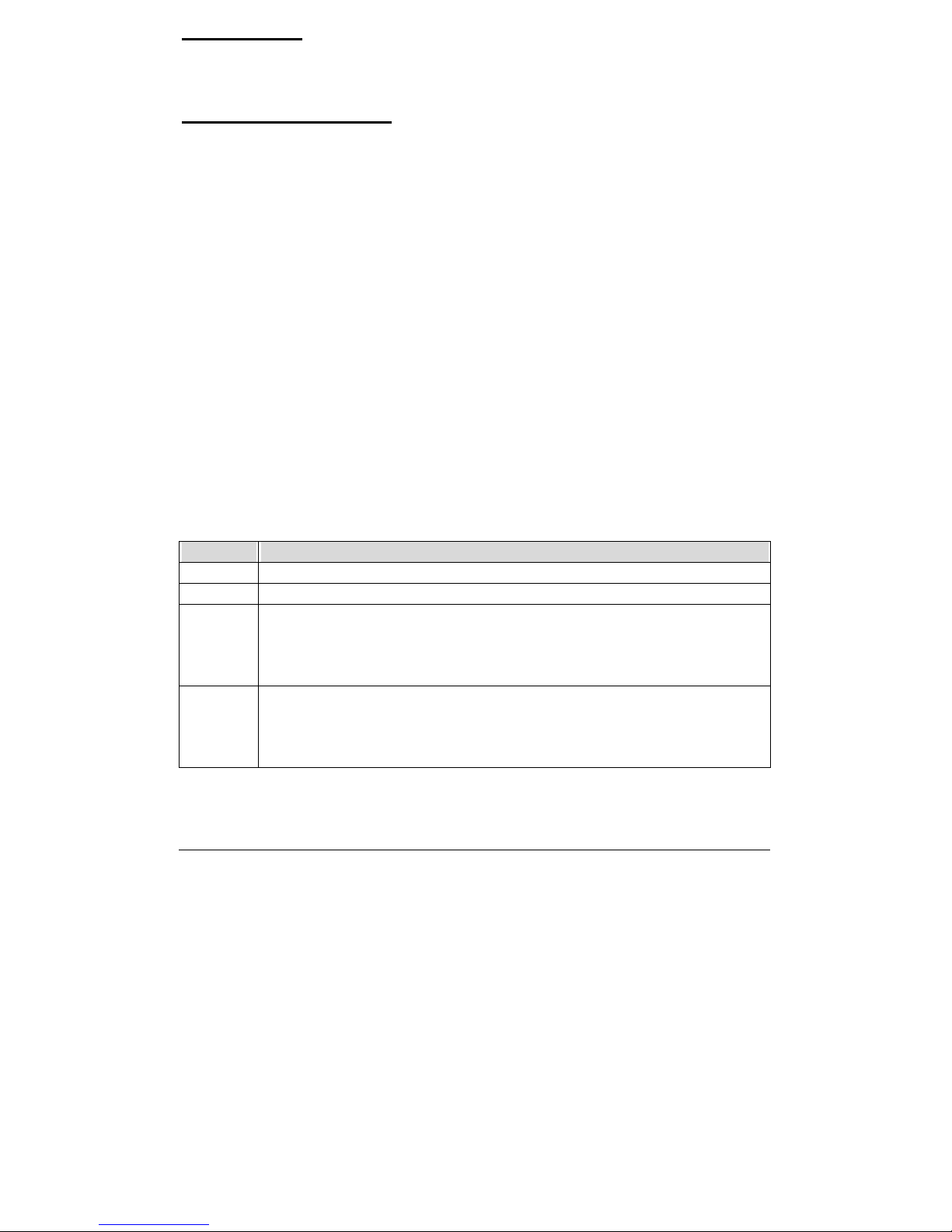
Ϩ! Parallel Port Mode:
This option specifies the parallel port mode. ECP and EPP are both
bi-directional data transfer schemes that adhere to the IEEE P1284
specifications. This Parallel Port Mode includes four options “Normal”,
“Bi-Dir”, “EPP”, and “ECP”.
Setting Description
Normal Uni-direction operation at normal speed
Bi-Dir Bi-direction operation at normal speed
EPP
The parallel port can be used with devices that adhere to the Enhanced
Parallel Port (EPP) specification. EPP uses the existing parallel port
signals to provide asymmetric bi-directional data transfer driven by the
host device.
ECP
The parallel port can be used with devices that adhere to the Extended
Capabilities Port (ECP) specification. ECP uses the DMA protocol to
achieve data transfer rates up to 2.5 Megabits per second. ECP provides
symmetric bi-directional communication.
Ϩ! EPP Version:
This option is only valid if the Parallel Port Mode option is set to EPP. This
Page 39

3-19
Ϩ! Parallel Port DMA Channel:
This option is only available if On Board Parallel Port is set to fixed I/O
address and the setting of Parallel Port Mode is ECP. This option sets the
DMA channel used by ECP-capable parallel port.
Ϩ! Parallel Port IRQ:
This option is only valid if the Onboard Parallel Port option is not set to
Disabled. This option sets the IRQ used by the parallel port.
On Board IDE
This option specifies the onboard IDE controller channels that will be used.
The settings are Disabled, Primary, Secondary, or Both.
Page 40

3-20
This setup describes current system status detected from hardware monitor
controller. The status showed on screen will include :
zThere are two on-board temperature sensors, TSENS1, and TSENS2.
zCurrent System Temperature (Generally indicates the inside
temperature of chassis or surface temperature of SBC)
zCurrent CPU Fan Speed
zCurrent Chassis Fan Speed
zSystem operating voltage includes “CPU Vcore”, “+2.500V”,
“+3.300”, “+5.000V”, “+12.000V”.
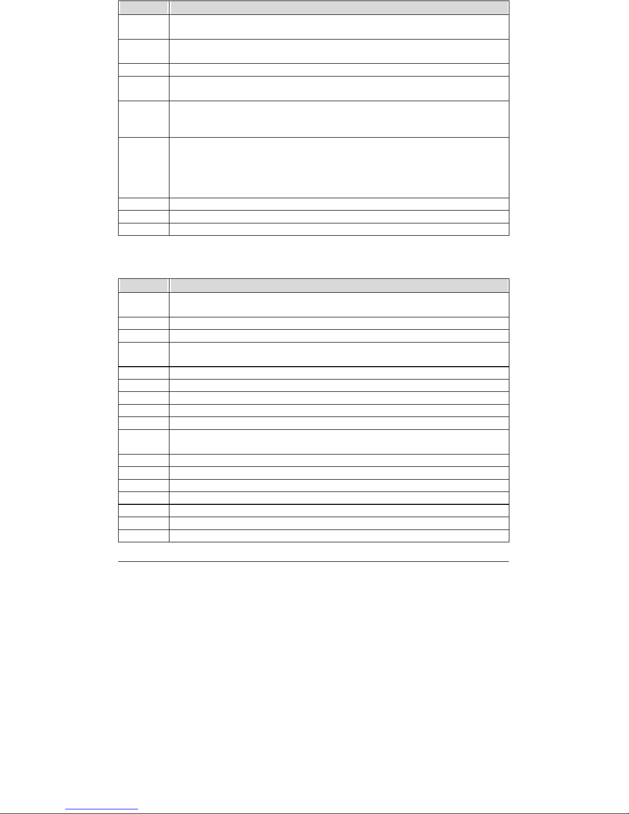
3.11 BIOS POST Check Point List
AMIBIOS provides all IBM standard Power On Self Test (POST) routines as
well as enhanced AMIBIOS POST routines. The POST routines support CPU
internal diagnostics. The POST checkpoint codes are accessible via the
Manufacturing Test Port (I/O port 80h).
Whenever a recoverable error occurs during the POST, the system BIOS will
display an error message describing the message and explaining the problem in
detail so that the problem can be corrected.
During the POST, the BIOS signals a checkpoint by issuing one code to I/O
address 80H. This code can be used to establish how far the BIOS has executed
through the power-on sequence and what test is currently being performed. This is
done to help troubleshoot faulty system board.
If the BIOS detects a terminal error condition, it will halt the POST process
and attempt to display the checkpoint code written to port 80H. If the system hangs
before the BIOS detects the terminal error, the value at port 80H will be the last
test performed. In this case, the terminal error cannot be displayed on the
screen. The following POST checkpoint codes are valid for all AMIBIOS products
with a core BIOS date of 07/15/95 version 6.27 (Enhanced).
Page 41
3-21
Code Description
D0
NMI is disabled. CPU ID saved. INIT code checksum verification will be
started.
D1
Initializing the DMA controller, performing the keyboard controller BAT
test, starting memory refresh, and going to 4GB flat mode.
D3 To start memory sizing.
D4
Returning to real mode. Executing any OEM patches and setting the stack
next.
D5
Passing control to the uncompressed code in shadow RAM at E000:0000h.
The INIT code is copied to segment 0 and control will be transferred to
segment 0.
D6
Control is in segment 0. Next, checking if <Ctrl><Home> was pressed and
verifying the system BIOS checksum.
If either <Ctrl><Home> was pressed or the system BIOS checksum is bad,
next will go to checkpoint code E0h.
Otherwise, going to checkpoint code D7h.
D7 To pass control to interface module.
D8 Main BIOS runtime code is to be decompressed.
D9 Passing control to the main system BIOS in shadow RAM next.
Bootblock Recovery Codes — The bootblock recovery
checkpoint hex codes are listed in order of execution :
Code Description
E0
The onboard floppy controller if available is initialized. Next, beginning the
base 512KB memory test.
E1 Initializing the interrupt vector table next.
E2 Initializing the DMA and Interrupt controllers next.
E6
Enabling the floppy drive controller and Timer IRQs. Enabling internal cache
memory.
ED Initializing the floppy drive.
EE Start looking for a diskette in drive A: and read first sector of the diskette.
EF A read error occurred while reading the floppy drive in drive A: .
F0 Next, searching for the AMIBOOT.ROM file in the root directory.
F1 The AMIBOOT.ROM file is not in the root directory.
F2
Next, reading and analyzing the floppy diskette FAT to find the clusters
occupied by the AMIBOOT.ROM file.
F3 Start reading AMIBOOT.ROM file, cluster by cluster.
F4 The AMIBOOT.ROM file is not the correct size.
F5 Next, disabling internal cache memory.
FB Next, detecting the type of Flash ROM.
FC Erasing the Flash ROM.
FD Programming the Flash ROM
FF Flash ROM programming was successful. Next, restarting the system BIOS.
Page 42

3-22
are uncompressed in F0000h shadow RAM.
Code Description
03 The NMI is disabled. Next, checking for a soft reset or a power on condition.
05 The BIOS stack has been built. Next, disabling cache memory.
06 Uncompressing the POST code next.
07 Next, initializing the CPU and the CPU data area.
08 The CMOS checksum calculation is done next.
0B
Next, performing any required initialization before the keyboard BAT
command is issued.
0C
The keyboard controller input buffer is free. Next, issuing the BAT
command to the keyboard controller.
0E
The keyboard controller BAT command result has been verified. Next,
performing any necessary INIT after the K/B controller BAT command test.
0F The keyboard command byte is written next.
10 Next, issuing the pin 23 and 24 blocking and unblocking commands.
11 Next, checking if the <End> or <Ins> keys were pressed during power on.
12
To initialize CMOS if the initialize CMOS RAM in every boot is set or the
<End> key is pressed. Going to disable DMA and Interrupt controllers.
13
The video display has been disabled. Port B has been initialized. Next,
initializing the chipset.
14 The 8254 timer test will begin next.
19 The 8254 timer test is over. Starting the memory refresh test next.
1A The memory refresh line is toggling. Checking the 15us on/off time next.
23
Reading the 8042 input port and disabling the MEGAKEY Green PC feature
next. Making the BIOS code segment writable and performing any necessary
configuration before initializing the interrupt vectors.
24
The configuration or setup required before interrupt vector initialization has
completed. Interrupt vector init. is about to begin
25
Interrupt vector initialization is done. Clearing the password if the POST
DIAG switch is on.
27 Any initialization before setting video mode to be done.
28 Going for monochrome mode and color mode setting.
2A Bus initialization system, static, output devices will be done next, if present.
2B
Passing control to the video ROM to perform any required configuration
before the video ROM test.
2C To look for optional video ROM and give control.
2D
The video ROM has returned control to BIOS POST. Performing any
required processing after the video ROM had control.
2E
Completed post-video ROM test processing. If the EGA/VGA controller is
not found, performing the display memory read/write test next.
2F EGA/VGA not found. Display memory R/W test about to begin.
30 Display memory R/W test passed. Look for retrace checking next.
31 Display memory R/W test or retrace checking failed. To do alternate display
Page 43

3-23
retrace checking.
34 Video display checking is over. Setting the display mode next.
37 The display mode is set. Displaying the power on message next.
38 Initializing the bus input, IPL, and general devices next, if present.
39 Displaying bus initialization error message.
3A
The new cursor position has been read and saved. Displaying the Hit <DEL>
message next.
40 Preparing the descriptor tables next.
42 Entering protected mode for the memory test next.
43 Entered protected mode. Enabling interrupts for diagnostics mode next.
44
Interrupts enabled if the diagnostics switch is on. Initializing data to check
memory wraparound at 0:0 next.
45
Data initialized. Checking for memory wraparound at 0:0 and finding the
total system memory size next.
46
The memory wraparound test has completed. The memory size calculation
has been done. Writing patterns to test memory next.
47
The memory pattern has been written to extended memory. Writing patterns
to the base 640 KB memory test.
48
Patterns written in base memory. Determining the amount of memory below
1MB next.
49
The amount of memory below 1MB has been found and verified.
Determining the amount of memory above 1MB memory next.
4B
The amount of memory above 1MB has been found and verified. Checking
for a soft reset and clearing the memory below 1MB for the soft reset next.
If this is a power on situation, going to checkpoint 4Eh next.
4C
The memory below 1MB has been cleared via a soft reset. Clearing the
memory above 1MB next.
4D
The memory above 1MB has been cleared via soft reset. Saving the memory
size next. Going to checkpoint 52h next.
4E
The memory test started, but not as the result of a soft reset. Displaying the
first 64KB memory size next.
4F
Memory size display started. This will be updated during memory test.
Performing the sequential and random memory test next.
50
Memory testing/initialization below 1MB completed. Going to adjust
displayed memory size for relocation and shadowing.
51
The memory size display was adjusted for relocation and shadowing.
Testing the memory above 1MB next.
52
The memory above 1MB has been tested and initialized. Saving the memory
size information next.
53
The memory size information and the CPU registers are saved. Entering
real mode next.
54
Shutdown was successful. The CPU is in real mode. Disabling the Gate A20
line, parity, and the NMI next.
57 The A20 address line, parity, and the NMI are disabled. Adjusting the
Page 44

3-24
Hit <DEL>
message next.
59
The Hit <DEL> message is cleared. The <WAIT…> message is displayed.
Staring the DMA and interrupt controller test next.
60 The DMA page register test passed. To do DMA#1 base register test.
62 DMA#1 base register test passed. To do DMA#2 base register test.
65 DMA#2 base register test passed. To program DMA unit 1 and 2.
66 DMA unit 1 and 2 programming over. To initialize 8259 interrupt controller.
7F Extended NMI sources enabling is in progress.
80
The keyboard test has started. Clearing the output buffer and checking for
stuck keys. Issuing the keyboard reset command next.
81
A keyboard reset error or stuck key was found. Issuing the keyboard
Controller interface test command next.
82
The keyboard controller interface test completed. Writing the command byte
and initializing the circular buffer next.
83 Command byte written, Global data init done. To check for lock-key.
84
Locked key checking is over. Checking for a memory size mismatch with
CMOS RAM data next.
85
The memory size check is done. Displaying a soft error and checking for a
password or bypassing Setup next.
86 Password checked. About to do programming before setup.
87
The programming before Setup has completed. Uncompressing the Setup
code and executing the AMIBIOS Setup utility next.
88
Returned from CMOS setup program and screen is cleared. About to do
programming after setup.
89
The programming after Setup has completed. Displaying the power on
Screen message next.
8B
The first screen message has been displayed. The <WAIT…> message is
displayed. Performing the PS/2 mouse check and extended BIOS data
area allocation check next.
8C Programming the Setup options next.
8D Going for hard disk controller reset.
8F Hard disk controller reset done. Floppy setup to be done next.
91
The floppy drive controller has been configured. Configuring the hard disk
drive controller next.
95 Initializing the bus option ROMs from C800 next.
96 Initializing before passing control to the adaptor ROM at C800.
97
Initialization before the C800 adaptor ROM gains control has completed.
The adaptor ROM check is next.
98
The adaptor ROM had control and has now returned control to BIOS POST.
Performing any required processing after the option ROM returned control.
99
Any initialization required after the option ROM test has completed.
Configuring the timer data area and printer base address next.
9A
Return after setting timer and printer base address. Going to set the RS-232
base address.
9B Returned after setting the RS-232 base address. Performing any required
Page 45

3-25
Coprocessor next.
9D Coprocessor initialized. Going to do any initialization after Coprocessor test.
9E
Initialization after the Coprocessor test is complete. Checking the extended
keyboard, keyboard ID, and Num Lock key next. Issuing the keyboard ID
command next.
A2 Displaying any soft errors next.
A3 Soft error display complete. Going to set keyboard typematic rate.
A4 Keyboard typematic rate set. To program memory wait states.
A5
Memory wait state programming is over. Clearing the screen and enabling
parity and the NMI next.
A7
NMI and parity enabled. Performing any initialization required before
passing control to the adaptor ROM at E000 next.
A8
Initialization before passing control to the adaptor ROM at E000h completed.
Passing control to the adaptor ROM at E000h next.
A9
Returned from adaptor ROM at E000h control. Performing any initialization
required after the E000 option ROM had control next.
AA
Initialization after E000 option ROM control has completed. Displaying the
system configuration next.
AB Building the multiprocessor table, if necessary.
AC Uncompressing the DMI data and initializing DMI POST next.
B0 The system configuration is displayed.
B1 Copying any code to specific areas.
00
Code copying to specific areas is done. Passing control to INT 19 h boot
loader next.
3.12 Flash BIOS Utility
Utilize AMI Flash BIOS programming utility to update on-board BIOS for the
future new BIOS version. Please contact your technical window to get this utility if
necessary.
NOTE : Remark or delete any installed Memory Management Utility (such as
HIMEM.SYS, EMM386.EXE, QEMM.EXE, …, etc.) in the
CONFIG.SYS files before running Flash programming utility.
Page 46
I
of CPU Board
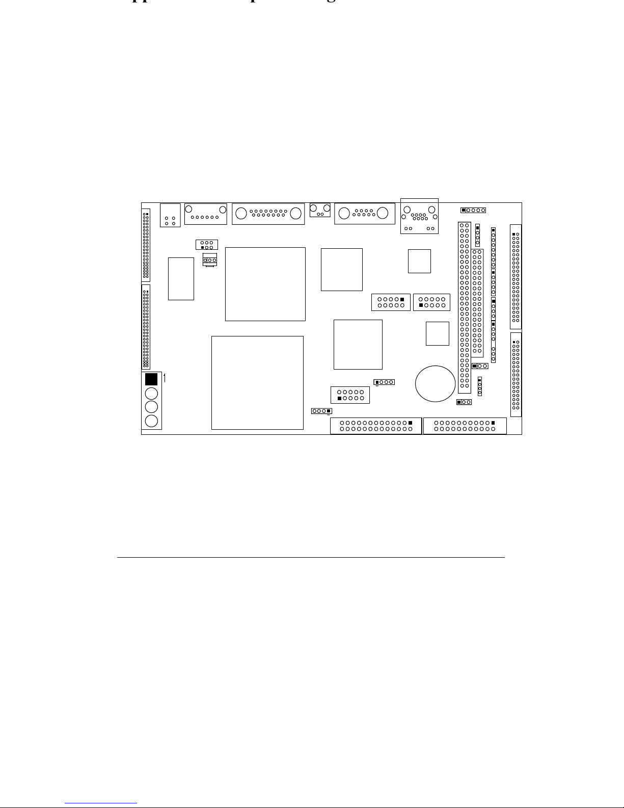
This Appendix provides information on Jumper Setting and Connectors List
of CPU Board, WEB-6580.
3.13 Jumper Location
˝˄ˆ
˄
˝˅
˟˔ˡ˄
˝˄ˊ
˝ˣ˅
˅˄
˅˄ ˅˅
˟ˣ ˧˄
˄ˇ˄
˄ˆ ˅ˉ
˝˄ˇ
˝˄ˈ
˝˄ˉ
ˌ˄˃
˄˅
˝ˌ
˅˄
˄˃ˌ
˝˄˃
ˌ˄˃
˄˅
˦ˣ˞˄
˝˄˞ˠ˄
˝ˈ
˝ˇ
˔˖ˌˊ
˥˧˟ˋ˄˃ ˃˕˟
˕˜ˢ˦
˩˧ˋ˅˖ˉ ˋˉ˕
˖ˣ˨
˩˧ˋˉ˃ˉ
˝˄ˌ
˝ˋ
˖˟˞
˝˅˄
˅˄
˝˅˅
ˊˋ
˄˅
˖ˡ˄
˅˄
˕˧˄
˄
˝˄˅
˜˗˘ ˄
˅˄
ˇˆ ˇˇ
˙˗˗˄
˅˄
ˆˆ ˆˇ
˝ˊ
˄
˜˥ ˄
˄
˝ˣ˄
˄
˝ˉ
˄
˝˄˄
˄
˄
˝ˆ
˖˄ ˗˄
˄
˝˄ˋ
˔˄ ˕ ˄
Page 47
II
3.14.1 Jumper Notes
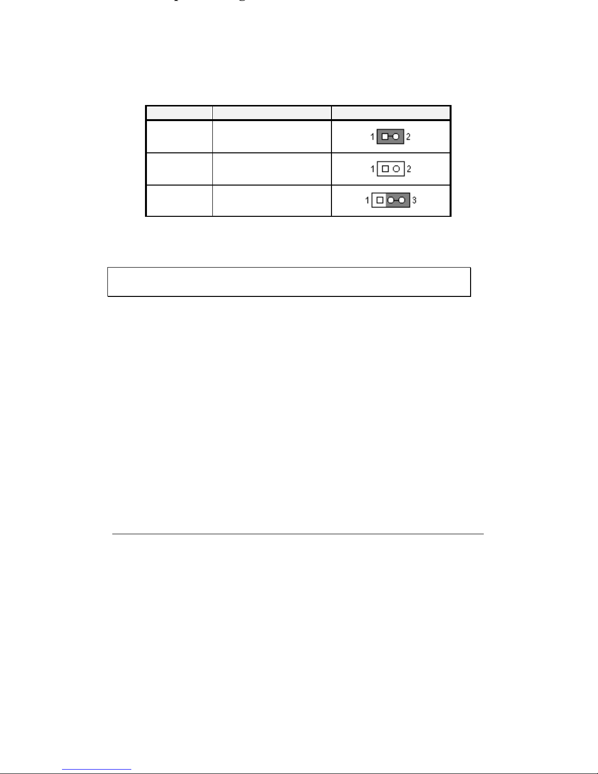
To close or enable a setting, put a jumper cap over the jumper pins. To open or
disable a setting, make sure there is no jumper cap covering the jumper pins. See
the table below for an illustration.
Notation Description Illustration
CLOSE Pins 1 & 2 closed
OPEN Pins 1 & 2 open
2-3 Pins 2 & 3 closed
Table Jumper Setting Example
Note : In this chapter, settings which are marked with h are default factory
settings.
Page 48
III
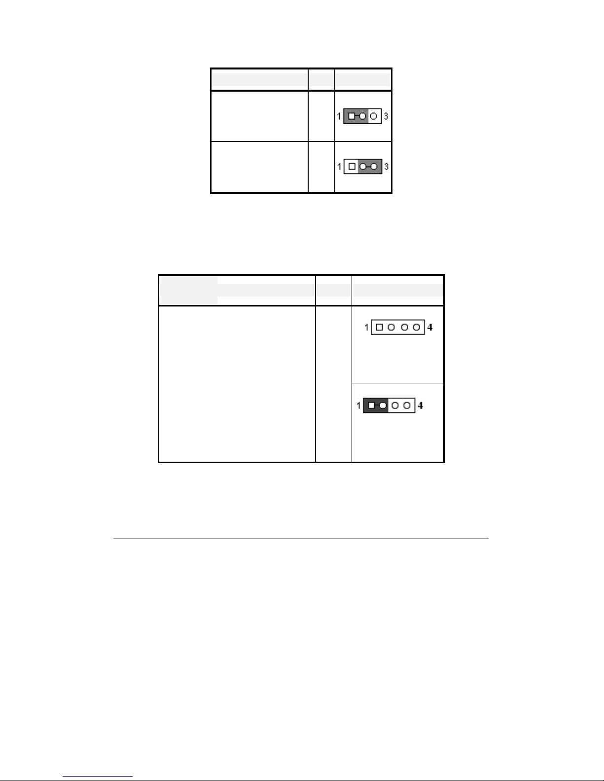
RTC CMOS Clear Jumper Setting (J12)
Description JP12 Illustration
Normal operation h
1-2
Clear CMOS content 2-3
Watch-Dog Timer Jumper Setting (JP1)
Description JP1 Illustration
h
Disable
Disable/Enable WDT function 1-2
Enable
Page 49
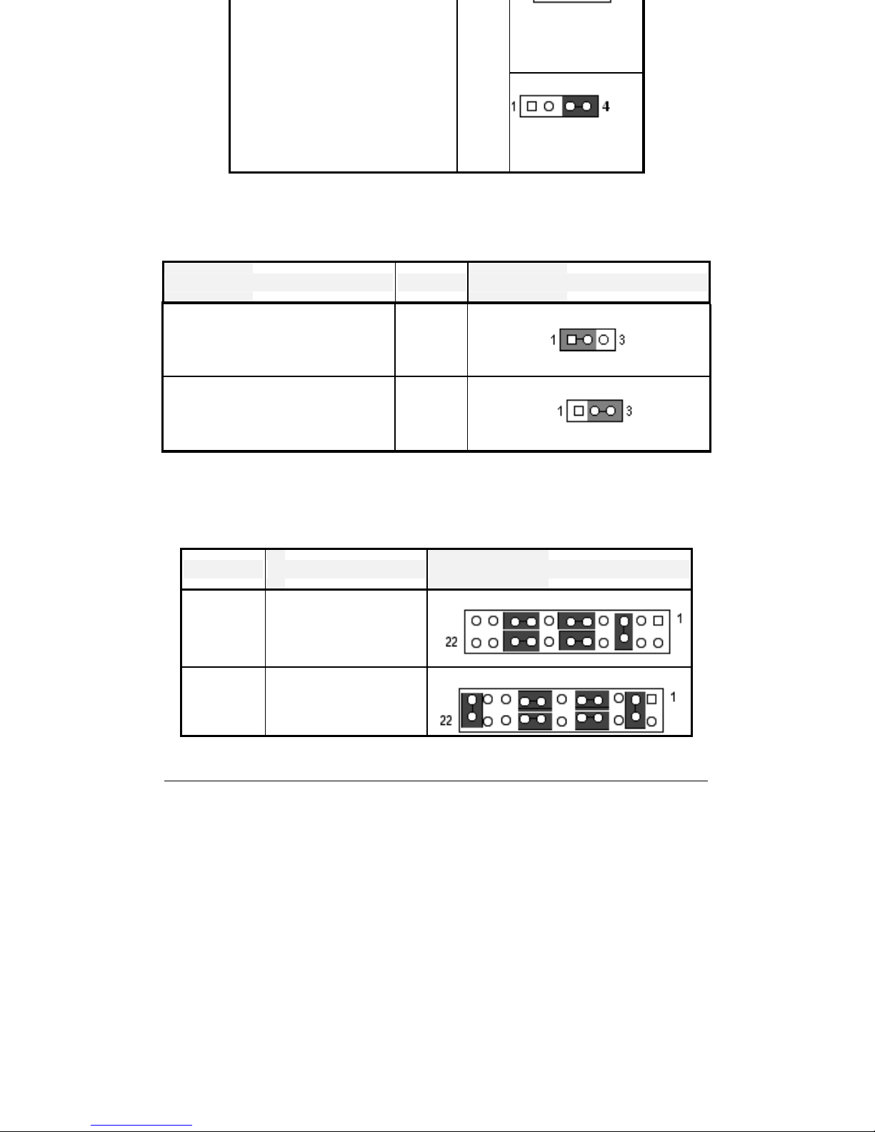
IV
h
0543H
I/O address for S/W programming 3-4
0443H
Panel Voltage Level Selection (J18)
Description J18 Illustration
5V 1-2
3V 2-3
h
RS232/422/485 Selection (JP2)
Description JP2 Illustration
RS232
5-6 , 9-11 , 10-12 ,
15-17 , 16-18
h
RS422
3-4 , 7-9 , 8-10 , 13-15 ,
14-16 , 21-22
Page 50
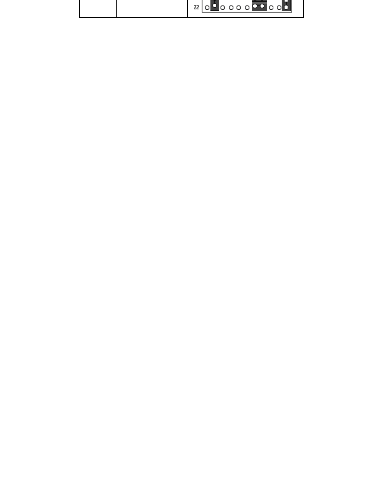
V
RS485 1-2
, 7-9 , 8-10 , 19-
20
Page 51
VI
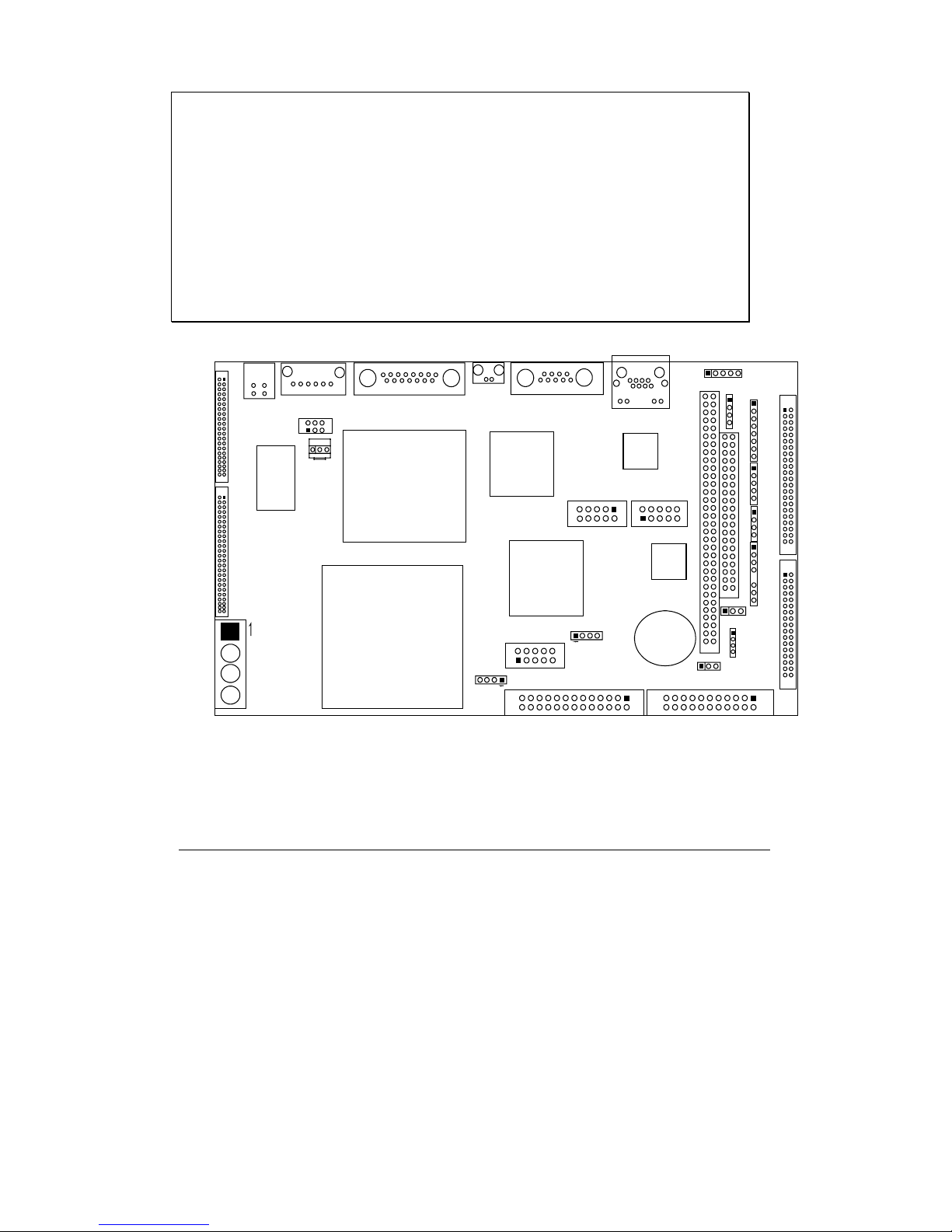
3.15.1 Connectors Location
CAUTION:
When connecting the power connector to the motherboard, make sure that the
system is not connected to an electrical outlet.
When connecting a signal cable (also called ribbon cable), Pin 1 of the cable
should be aligned with Pin 1 of the connector on the motherboard. Pin 1
side of the cable is identified by a color, usually red, stripe. Pin 1 of the
motherboard connector is identified by the number 1 imprinted or an
additional shading on the board.
˝˄ˆ
˄
˝˅
˟˔ˡ˄
˝˄ˊ
˝ˣ˅
˅˄
˅˄ ˅ ˅
˟ˣ ˧˄
˄ˇ˄
˄ˆ ˅ ˉ
˝˄ˇ
˝˄ˈ
˝˄ˉ
ˌ˄˃
˄˅
˝ˌ
˅˄
˄˃ˌ
˝˄˃
ˌ˄˃
˄˅
˦ˣ˞˄
˝˄˞ˠ˄
˝ˈ
˝ˇ
˔˖ˌˊ
˥˧˟ˋ˄˃ ˃˕˟
˕˜ˢ˦
˩˧ˋ˅˖ˉ ˋˉ˕
˖ˣ˨
˩˧ˋˉ˃ˉ
˝˄ˌ
˝ˋ
˖˟˞
˝˅˄
˅˄
˝˅˅
ˊˋ
˄˅
˖ˡ˄
˅˄
˕˧˄
WPC-651 TOP SIDE
˄
˝˄˅
˜˗˘ ˄
˅˄
ˇˆ ˇˇ
˙˗˗˄
˅˄
ˆˆ ˆˇ
˝ˊ
˄
˜˥ ˄
˄
˝ˣ˄
˄
˝ˉ
˄
˝˄˄
˄
˄
˝ˆ
˖˄ ˗˄
˄
˝˄ˋ
˔˄ ˕ ˄
Page 52
VII
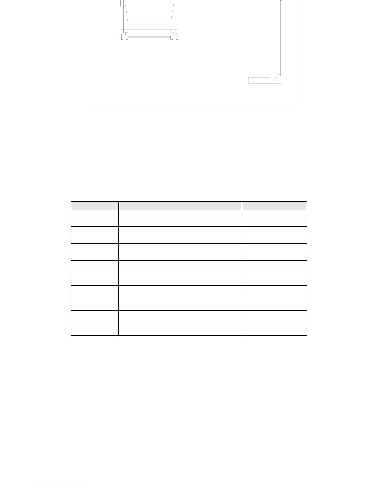
˝˅˃
˦ˢ˗˜ˠˠ˄
WPC-651 BOTTOM SIDE
3.15.2 Connectors List
The connectors on the WPC-651 are used to connect external devices
such as hard disk drives, printers, keyboard, CRT, panel, serial ports, etc.
Specifically, WPC-651 has the following connectors:
CONNECTOR FUNCTION REMARK
J1 VGA Interface DSUB-15
J2 COM1 Serial Interface (RS232) DSUB-9
J3 External Panel Power Connector 5 pin
J4 Reset Button
J5 Power/HDD LED
J6 CD-ROM Audio In Connector 4-pin Mini-Din
J7 Front Panel 8-pin
J8 Panel LVDS Interface
J9 COM2 Serial Port (RS232/422/485) 2x5 pin header
J10 Audio Interface 2x5 pin header
J11 CPLD Program Interface
J12 RTC CMOS Clear
J13 External –12/-5V Interface 4-pin Mini-Din
J14/J15 PC/104 Bus Connector
J16 External USB Interface
Page 53
VIII
J18 LCD Voltage Select
J19 Standard 5-1/4” Disk Power Connector Big 4 Pin
J20 Compact Flash Card
J22 Panel type select
BT1 Li battery for RTC
FDD1 Floppy connector 2x17 pin header
IDE1 IDE1 (Primary) interface
LPT1 Parallel port connector 2x13 pin header
IR1 Standard IrDA (Infrared) port
CN1 Panel TTL interface
LAN1 RJ-45 Ethernet connector
KM1 PS/2 keyboard & mouse connector 6-pin Mini-Din
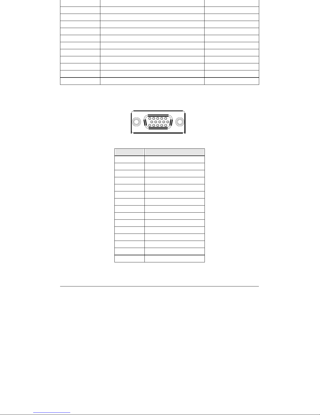
On Board VGA D-SUB15 Connector (J1)
PIN No. Signal Description
1 Red
2Green
3Blue
4N/C
5 Ground
6 Ground
7 Ground
8 Ground
9VCC
10 Ground
11 N/C
12 DDC Data
13 HSYNC
14 VSYNC
15 DDC Clock
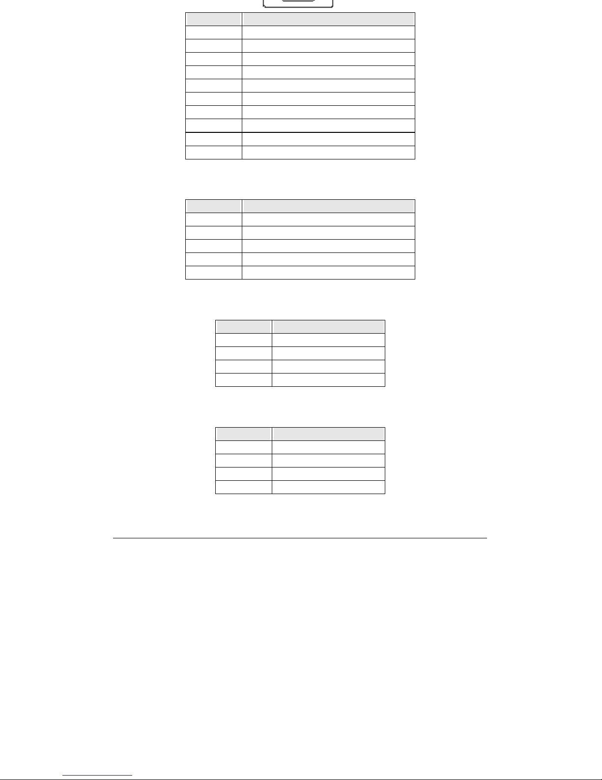
COM1 DSUB9 Connector (J2)
Page 54
IX
PIN No. Signal Description
1 Data Carrier Detect
2 Received Data
3 Transmit Data
4 Data Terminal Ready
5 Ground
6 Data Set Ready
7 Request To Send
8 Clear To Send
9 Ring Indicator
10 Not used
External Panel Power Connector (J3)
PIN No. Signal Description
1NC
2 Ground
3 +12V
4 Ground
5 Enablk
Reset Button (J4)
PIN No. Signal Description
1Reset
2 Ground
3 Ground
4 Ground
Power / HDD LED (J5)
PIN No. Signal Description
1 Power_5V
2 Ground
3 HDD_5V
4 HDD_Active
CD-ROM Audio In Connector (J6)
Page 55
X
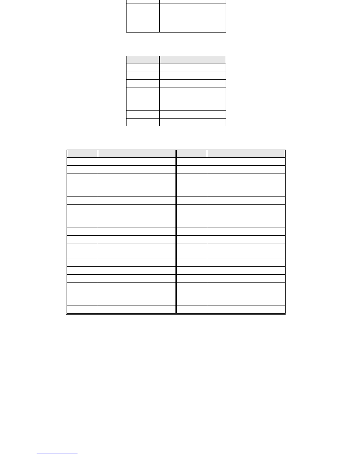
2 Ground
3 Ground
4CD_R
Front Panel Interface (J7)
PIN No. Signal Description
1 ACTLED
2 SPDLED
3 LINKLED
4 +3V
5 PWRLED
6 HD_LED
7RST
8 Ground
Panel LVDS Interface (J8)
PIN No. Signal Description PIN No. Signal Description
1 +LCD 2 +LCD
3 +LCD 4 +LCD
5 Ground 6 Ground
7 +12V 8 Y0M
9 +12V 10 Y0P
11 Ground 12 Ground
13 +5V 14 Ground
15 +5V 16 Y1M
17 Ground 18 Y1P
19 SKBDATA 20 Ground
21 Ground 22 Ground
23 SMSDATA 24 Y2M
25 Ground 26 Y2P
27 SKBCLK 28 Ground
29 Ground 30 Ground
31 SMSCLK 32 YCM
33 Ground 34 YCP
35 RXD#1 36 Ground
37 Ground 38 VEEON
39 TXD#1 40 Ground
Page 56
XI
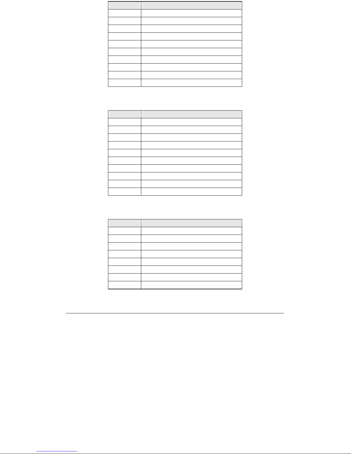
PIN No. Signal Description
1 Data Carrier Detect
2 Received Data
3 Transmit Data
4 Data Terminal Ready
5 Ground
6 Data Set Ready
7 Request To Send
8 Clear To Send
9 Ring Indicator
10 Not used
AUDIO Interface (J10)
PIN No. Signal Description
1MICPWR
2N/C
3LINE_L
4 Ground
5LINE_R
6 Ground
7 LOUT_L
8 Ground
9 LOUT_R
10 Ground
CPLD Program Connector (J11)
PIN No. Signal Description
1 VCC
2TDO
3TDI
4N/C
5N/C
6TMS
7 Ground
8TCK
External –12/-5V Connector (J13)
Page 57

XII
2 GND
3 GND
4 -12V
PC/104 Bus Connector (J14/15)
PIN No. Signal Description PIN No. Signal Description
A1 IOCHK B1 Ground
A2 D7 B2 RESET
A3 D6 B3 VCC
A4 D5 B4 IRQ9
A5 D4 B5 -5V
A6 D3 B6 DRQ2
A7 D2 B7 -12V
A8 D1 B8 PULL-VCC
A9 D0 B9 +12V
A10 IOCHRDY B10 Ground
A11 AEN B11 SMEMW
A12 A19 B12 SMEMR
A13 A18 B13 IOW
A14 A17 B14 IOR
A15 A16 B15 DACK3
A16 A15 B16 DRQ3
A17 A14 B17 DACK1
A18 A13 B18 DRQ1
A19 A12 B19 REFRESH
A20 A11 B20 CLK
A21 A10 B21 IRQ7
A22 A9 B22 IRQ6
A23 A8 B23 IRQ5
A24 A7 B24 IRQ4
A25 A6 B25 IRQ3
A26 A5 B26 DACK2
A27 A4 B27 TC
A28 A3 B28 BALE
A29 A2 B29 VCC
A30 A1 B30 OSC
A31 A0 B31 Ground
A32 Ground B32 Ground
C1 Ground D1 Ground
Page 58
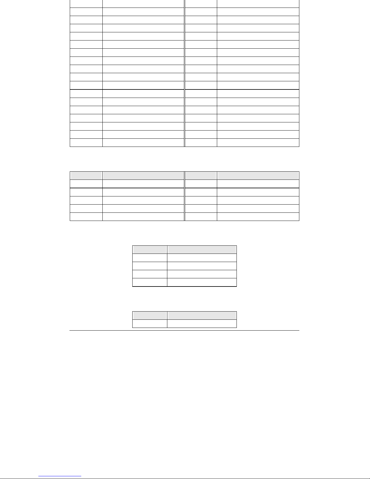
XIII
C3 LA23 D3 IOCS16
C4 LA22 D4 IRQ10
C5 LA21 D5 IRQ11
C6 LA20 D6 IRQ12
C7 LA19 D7 IRQ15
C8 LA18 D8 IRQ14
C9 LA17 D9 DACK0
C10 MEMR D10 DRQ0
C11 MEMW D11 DACK5
C12 D8 D12 DRQ5
C13 D9 D13 DACK6
C14 D10 D14 DRQ6
C15 D11 D15 DACK7
C16 D12 D16 DRQ7
C17 D13 D17 VCC
C18 D14 D18 MASTER
C19 D15 D19 Ground
C20 N/C D20 Ground
External USB (J16)
PIN No. Signal Description PIN No. Signal Description
1 +5V 2 NC
3 USBP0- 4 Ground
5 USBP0+ 6 USBP1+
7 Ground 8 USBP19 NC 10 +5V
External FDD Power Connector (J17)
PIN No. Signal Description
1 +5V
2 GND
3 GND
4 +5V
Standard 5-1/4” Disk Power Connector (J19)
PIN No. Signal Description
1 +12V
Page 59
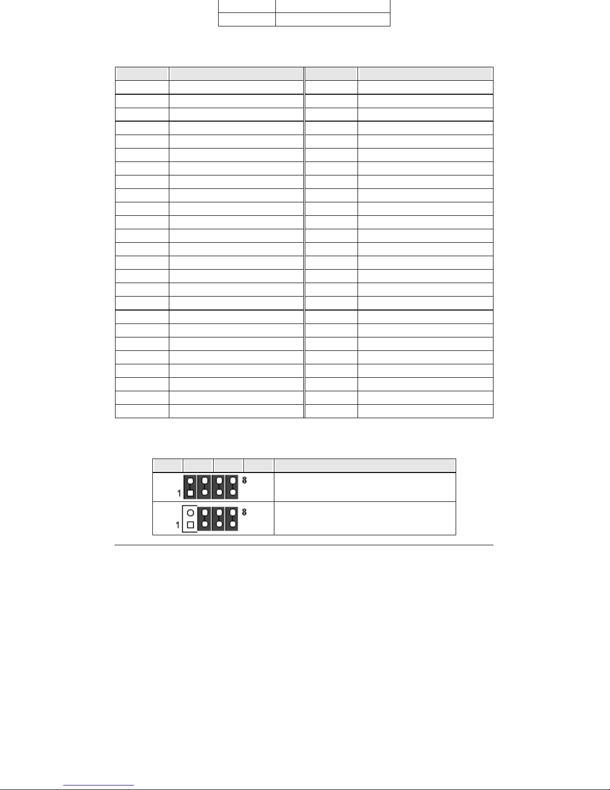
XIV
3GND
4 +5V
Compact Flash Card (J20)
PIN No. Signal Description PIN No. Signal Description
1 Ground 2 D3
3D4 4D5
5D6 6D7
7CS#0 8A10
9 ATA_SEL 10 A9
11 A8 12 A7
13 VCC 14 A6
15 A5 16 A4
17 A3 18 A2
19 A1 20 A0
21 D0 22 D1
23 D2 24 IOCS16
25 CD2 26 CD1
27 D11 28 D12
29 D13 30 D14
31 D15 32 CS1
33 VS1 34 IOR
35 IOW 36 WE#
37 INTRQ 38 VCC
39 CSEL 40 VS2
41 RESET 42 IOCHRDY
43 INPACK 44 REQ
45 DASP 46 PDIAG
47 D8 48 D9
49 D10 50 Ground
Panel Type Select (J22)
7-8 5-6 3-4 1-2 Panel Type
640x480 TFT
800x600 TFT
Page 60
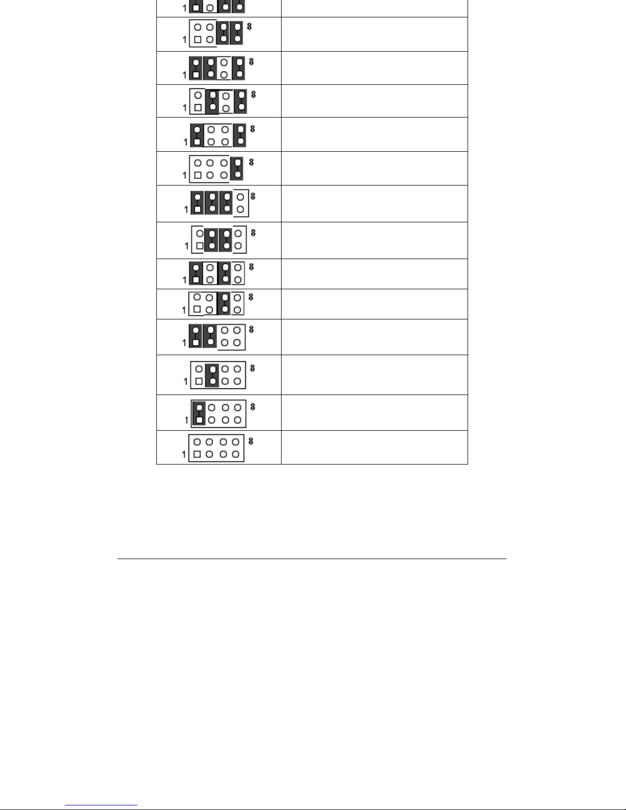
XV
1024x768 TFT 2pixel/clk at 32Mhz
1280x1024 TFT
640x480 DSTN
800x600 DSTN
1024x768 DSTN
1024x768 TFT 1pixel/clk at 65Mhz
640x480 TFT
800x600 TFT
1024x768 TFT
1280x1024 TFT
1400x1050 TFT 2pixel/clk at 54Mhz
800x600 DSTN
1024x768 DSTN
1280x1024 DSTN
Floppy Connector (FDD1)
Page 61

XVI
3 Ground 4 N/C
5 Ground 6 N/C
7 Ground 8 Index#
9 Ground 10 Motor ENA#
11 Ground 12 Drive Select B#
13 Ground 14 Drive Select A#
15 Ground 16 Motor ENB#
17 Ground 18 Direction#
19 Ground 20 Step#
21 Ground 22 Write Data#
23 Ground 24 Write Gate#
25 Ground 26 Track 0#
27 Ground 28 Write Protect#
29 Ground 30 Read Data#
31 Ground 32 Head Select#
33 Ground 34 Disk Change#
IDE1 ( Primary ) Connector ( IDE1 )
PIN No. Signal Description PIN No. Signal Description
1 RESET# 2 Ground
3 Data 7 4 Data 8
5 Data 6 6 Data 9
7 Data 5 8 Data 10
9 Data 4 10 Data 11
11 Data 3 12 Data 12
13 Data 2 14 Data 13
15 Data 1 16 Data 14
17 Data 0 18 Data 15
19 Ground 20 N/C
21 DMA REQ 22 Ground
23 IOW# 24 Ground
25 IOR# 26 Ground
27 IOCHRDY 28 Pull-down
29 DMA ACK# 30 Ground
31 INT REQ 32 N/C
33 SA1 34 ATA_SEL
35 SA0 36 SA2
37 CS0# 38 CS1#
39 HDD Active# 40 Ground
Page 62
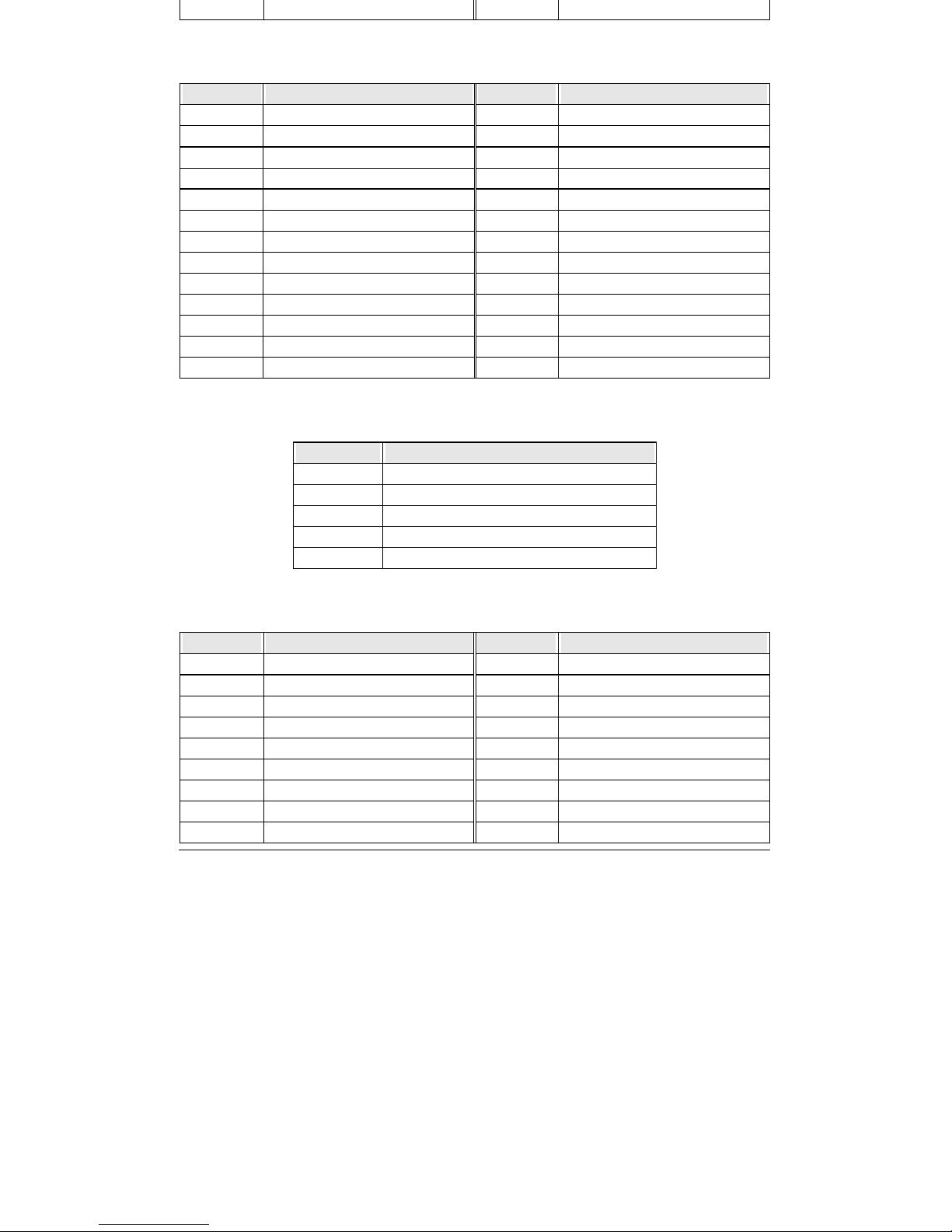
XVII
43 Ground 44 Ground
Parallel Port (LPT1)
PIN No. Signal Description PIN No. Signal Description
1 Strobe# 14 Auto Form Feed#
2 Data0 15 Error#
3 Data1 16 Initialization#
4 Data2 17 Printer Select IN#
5 Data3 18 Ground
6 Data4 19 Ground
7 Data5 20 Ground
8 Data6 21 Ground
9 Data7 22 Ground
10 Acknowledge# 23 Ground
11 Busy 24 Ground
12 Paper Empty 25 Ground
13 Printer Select 26 NC
Standard IrDA (IR1)
PIN No. Signal Description
1 +5V
2NC
3 IRRX
4 Ground
5IRTX
Panel TTL Connector (CN1)
PIN No. Signal Description PIN No. Signal Description
1 Ground 2 SHFCLK
3 Ground 4 HSYNC
5 VSYNC 6 Ground
7 FP0 8 FP1
9 FP2 10 FP3
11 Ground 12 Ground
13 FP4 14 FP5
15 FP6 16 FP7
17 Ground 18 Ground
Page 63
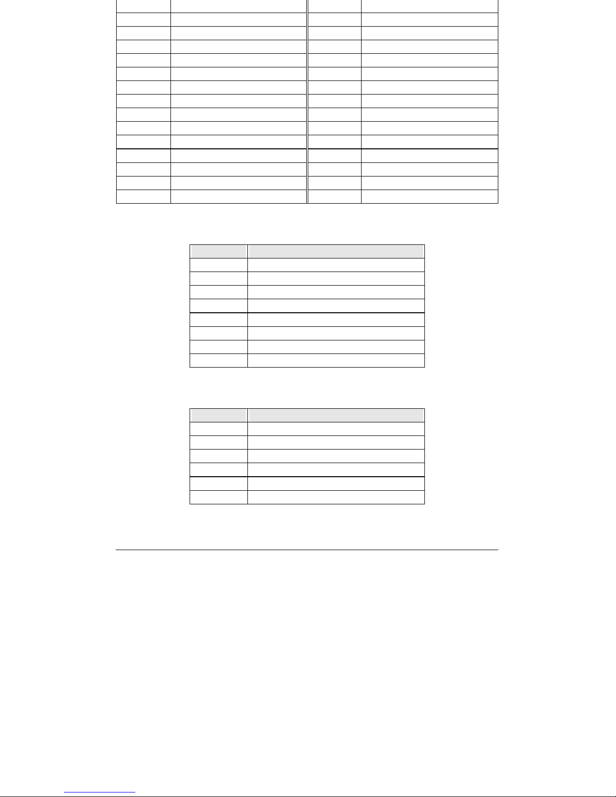
XVIII
21 FP10 22 FP11
23 Ground 24 Ground
25 FP12 26 FP13
27 FP14 28 FP15
29 Ground 30 Ground
31 FP16 32 FP17
33 FP18 34 FP19
35 Ground 36 Ground
37 FP20 38 FP21
39 FP22 40 FP23
41 Ground 42 Ground
43 N/C 44 N/C
45 DE 46 N/C
47 +LCD 48 +LCD
49 Ground 50 Ground
RJ-45_Ethernet Connector ( LAN1 )
PIN No. Signal Description
1TX+
2TX3RX+
4 Termination To Ground
5 Termination To Ground
6RX-
7 Termination To Ground
8 Termination To Ground
PS/2 Keyboard & Mouse (KM1)
PIN No. Signal Description
1 Keyboard Data
2 Mouse Data
3 Ground
4 +5V
5 Keyboard Clock
6 Mouse Clock
Page 64
XIX
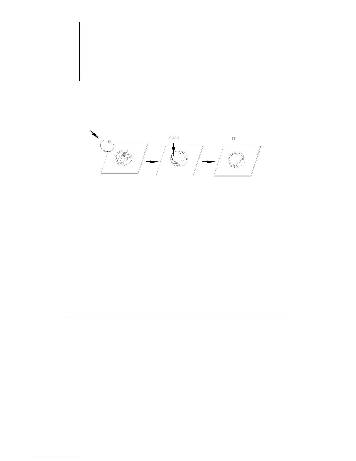
Follow below instructions and notice the caution for replacing and disposing of the
RTC Lithium battery CR2032 for safety consideration :
CAUTION:
z Danger of explosion if battery is incorrectly replaced.
z Replace only with the same or equivalent type recommended by the
manufacturer.
z Dispose of used batteries according to the manufacturer’s instruction.
(1) Install Battery Procedure
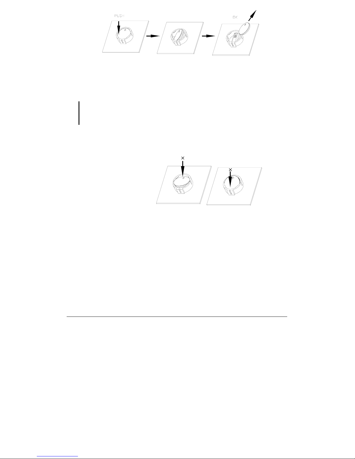
(2) Uninstall Battery Procedure
Page 65
XX
CAUTION:
z Do not install and press battery shown as below direction.
Page 66
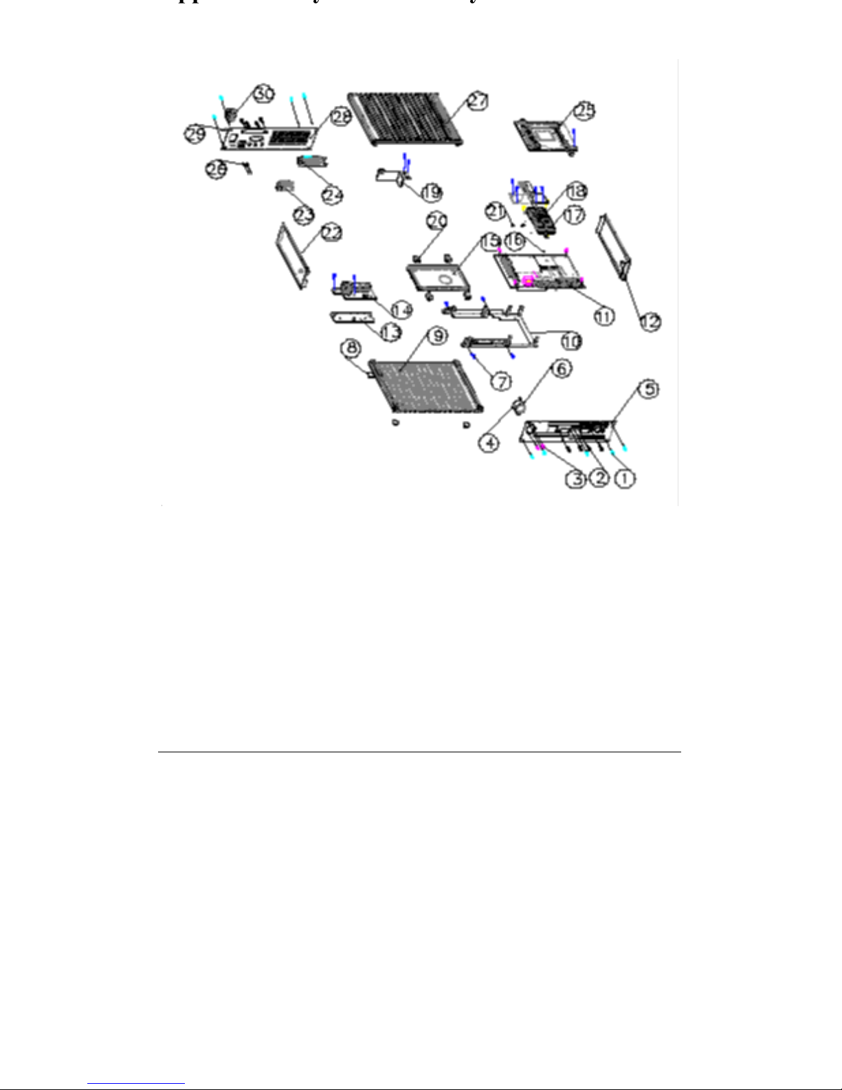
XXI
 Loading...