

Page 1

WMP-17F
Medical Panel PC
USER’S MANUAL
V1.0
Copyright© ,2016. All rights reserved
All other brand names are registered trademarks of their respective owners.
The information contained in this document is subject to change without notice.
Page 2

WMP-17F User’s manual
ii
Version Change History
Date
Version
Description
Remark
2016/11/2
1.0
First release
James
Page 3

WMP-17F User’s manual
iii
Acknowledgments
Intel® 6
th
generation Core i and Pentium are registered
trademarks of Intel® Corporation.
IBM, PC/AT, PS/2 are trademarks of International Business
Machines Corporation.
Microsoft
®
Windows is a registered trademark of Microsoft
®
Corporation.
RTL is a trademark of Realtek Semi-Conductor Co., Ltd.
C&T is a trademark of Chips and Technologies, Inc.
UMC is a trademark of United Microelectronics Corporation.
ITE is a trademark of Integrated Technology Express, Inc.
Intel is a trademark or registered trademark of Intel
Corporation.
Microsoft Windows is a registered trademark of Microsoft
Corporation.
Winbond is a registered trademark of Winbond Electronics
Corporation.
All other product names or trademarks are properties of
their respective owners.
Page 4

WMP-17F User’s manual
iv
FCC Class B
This equipment has been tested and found to comply with the limits for a
Class B digital device, pursuant to Part 18 of the FCC Rules.
These limits are designed to provide reasonable protection against harmful
interference when the equipment is operated in a residential environment.
This equipment generates, uses and can radiate radio frequency energy. If
not installed and used in accordance with this user manual, it may cause
harmful interference to radio communications.
Note that even when this equipment is installed and used in accordance
with this user manual, there is still no guarantee that interference will not
occur. If this equipment is believed to be causing harmful interference to
radio or television reception, this can be determined by turning the
equipment on and off. If interference is occurring, the user is encouraged
to try to correct the interference by one or more of the following measures:
Reorient or relocate the receiving antenna
Increase the separation between the equipment and the receiver
Connect the equipment to a power outlet on a circuit different from
that to which the receiver is connected
Consult the dealer or an experienced radio/TV technician for help
Warning:
Any changes or modifications made to the equipment which are
not expressly approved by the relevant standards authority could
void your authority to operate the equipment.
To avoid risk of electric shock, this equipment must only be
connected to a supply mains with protective earth.
Do not modify this equipment without authorization of the
manufacturer.
Page 5

WMP-17F User’s manual
v
Safety Instructions
Intended use
The WMP-17F is intended to serve as a medical monitor which is
designed for general purpose for hospital environment. It shall
not be used for life-supporting system.
Intended User profile
The equipment is intended for infant or adults by profession
Health care professionals.
Greeting & Setup
Thank you for purchasing the WMP-17F unit. We wish that this
unit will be durable and reliable in providing your medical
application needs. Please follow the instructions below to ensure
the unit continues to have high performance.
Unpacking
After opening the carton, there will be a medical panel PC unit
with an accessory box. Examine the contents to see if there are
damages to the unit and if all accessories are present.
Setting up
Please read this manual carefully and remember to keep this
manual for future reference.
Safety Instructions & Cleaning
The unit has undergone various tests in order to comply with
safety standards. Inappropriate use of the open frame unit may
be dangerous. Please remember to follow the instructions below
to insure your safety during the installation and operating
process.
Transporting & Placement of unit
1. When moving the unit on a cart; be very cautious. Quick
stops, excessive forces and uneven surfaces may cause
the cart to overturn thus risking the unit to fall to the
ground.
2. If the medical panel PC unit does fall to the ground,
immediately turn the power off and disconnect cords. Then
Page 6

WMP-17F User’s manual
vi
contact a service technician for repairs. Continual use of
the unit may result cause a fire or electric shock. Also, do
not repair the unit on your own.
3. Having two or more people transporting the display unit is
recommended. In addition, when installing the unit by
suspending it also requires two or more people.
4. Before suspending the unit, make sure the material used
for suspension is sturdy and stable. If not properly
suspended, the display unit may fall and cause serious
injury to people standing nearby as well as to the unit
itself.
5. If you wish to mount the display unit, remember to use
only the mounting hardware recommended by the
manufacturer.
Electrical and Power Source Related
1. This medical panel PC unit must operate on a power source
as shown on the specification label. If you are not sure
what type of power supply used in the area, consult your
dealer or local power supplier.
2. The power cords must not be damaged. Applied pressure,
added heat, and tugging may damage the power cord.
3. The power cord must be routed properly when setup takes
place. We advise that this aspect measure is to prevent
people from stepping on the cords or while the unit is
suspended to prevent flying objects from getting tangled
with the unit.
4. For plug-in equipment, the power outlet socket must be
located near the equipment and must be easily accessible.
5. Do not overload the AC outlets or extension cords.
Electrical shocks or fires may occur from overloading.
6. Do not touch the power source during a thunderstorm.
7. If your hands are wet, do not touch the plug.
8. Use your thumb and index finger, grip firmly on the power
cord to disconnect from the electrical socket. By pulling the
power cord, may result in damaging it.
Page 7

WMP-17F User’s manual
vii
9. If the unit is not going to be in use for an extended period
of time, remember to disconnect the unit.
10. The medical panel PC unit uses voltage between
100-240VAC. Connect the unit to a power source with the
same numerical value as shown. Please use only the power
cord provided by the dealer to ensure safety and EMC
compliance.
Various Factors of Environment
1. Do not insert objects into the openings.
2. Do not have liquids seep into the internal areas of the
medical panel PC unit.
3. Having liquids seep in or inserting objects into the unit
may result in electric shocks from taking and/or short
circuiting the internal parts.
4. Do not place the medical panel PC unit in the presence of
high moisture areas.
5. Do not install the medical panel PC unit in a wet
environment.
6. Do not place near unit near heat generating sources.
7. Do not place the unit in a location where it will come in
contact with fumes or steam.
8. Remember to keep the medical panel PC unit away from
the presence of dust.
9. If water has flow in or seep in, immediately disconnect the
open frame unit. Then contact a service technician for
repairs.
Ventilation Spacing
1. Do not cover or block the openings on the top and back
sides of the display unit. Inadequate ventilation may cause
overheating thus reducing the lifespan of the unit.
2. Unless proper ventilation is present, do not place unit in an
enclosed area; such as a built-in shelf. Keep a minimum
distance of 10 cm between the display unit and wall.
Page 8

WMP-17F User’s manual
viii
Operating principle
A Medical Panel PC has four main components: the
arithmetic logic unit (ALU), the control unit, the memory,
and the input and output devices (collectively termed I/O).
These parts are interconnected by buses, often made of
groups of wires.
The control unit, ALU, and registers are collectively known as
a central processing unit (CPU).
Inside each of these parts are thousands to trillions of small
electrical circuits which can be turned off or on by means of
an electronic switch. Each circuit represents a bit (binary
digit) of information so that when the circuit is on it
represents a "1", and when off it represents a "0" (in positive
logic representation). The circuits are arranged in logic gates
so that one or more of the circuits may control the state of
one or more of the other circuits.
Cleaning the unit
1. Remember to turn off the power source and to unplug the
cord from the outlet before cleaning the unit.
2. Carefully dismount the unit or bring the unit down from
suspension to clean.
3. Please use a dry soft cloth to clean the unit.
4. Take a dry cloth and wipe the unit dry. Remember to avoid
having liquids seep into the internal components and areas
of the medical panel PC unit.
Error message / Troubleshooting
No power
1. Connect the AC adapter to the computer, and
then plug it into an AC outlet.
2. Turn on the computer.
Servicing, Repairing, Maintenance & Safety Checks
1. If the unit is not functioning properly, observe the
performance level of the display closely to determine what
type of servicing is needed.
Page 9
WMP-17F User’s manual
ix
2. Do not attempt to repair the medical panel PC unit on your
own. Disassembling the cover exposes users’ to high
voltages and other dangerous conditions. Notify and
request a qualified service technician for servicing the unit.
3. To avoid risk of electric shock, this equipment must only be
connected to a supply mains with protective earth.
4. If any of the following situations occur turn the power
source off and unplug the unit. Then contact a qualified
service technician.
(a) A liquid was spilled on the unit or objects have fallen
into the unit.
(b) The unit is soaked with liquids.
(c) The unit is dropped or damaged.
(d) If smoke or strange odor is flowing out of the operating
unit.
(e) If the power cord or plug is damaged.
(f) When the functions of the unit are dysfunctional.
5. When replacement parts are needed for the medical panel
PC unit, make sure service technicians use replacement
parts specified by the manufacturer, or those with the
same characteristics and performance as the original
parts. If unauthorized parts are used it may result in
starting a fire, electrical shock and/or other dangers.
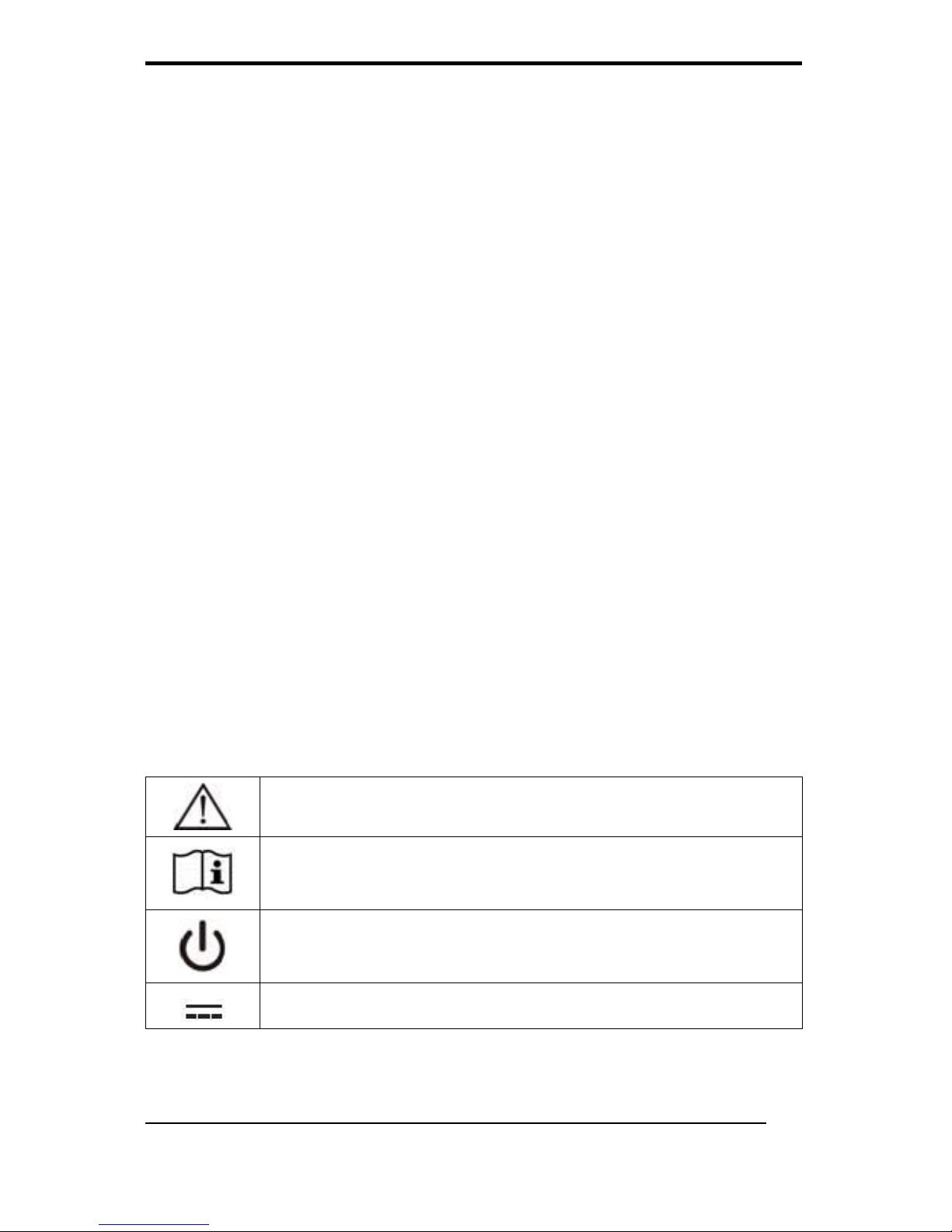
ISO 7000-0434 : Caution, consult ACCOMPANYING
DOCUMENTS.
ISO 7000-1641 : Follow operating instructions or
Consult instructions for use.
IEC 60417 -5009 : STAND-BY.
IEC 60417-5031 : Direct current.
Page 10
WMP-17F User’s manual
x
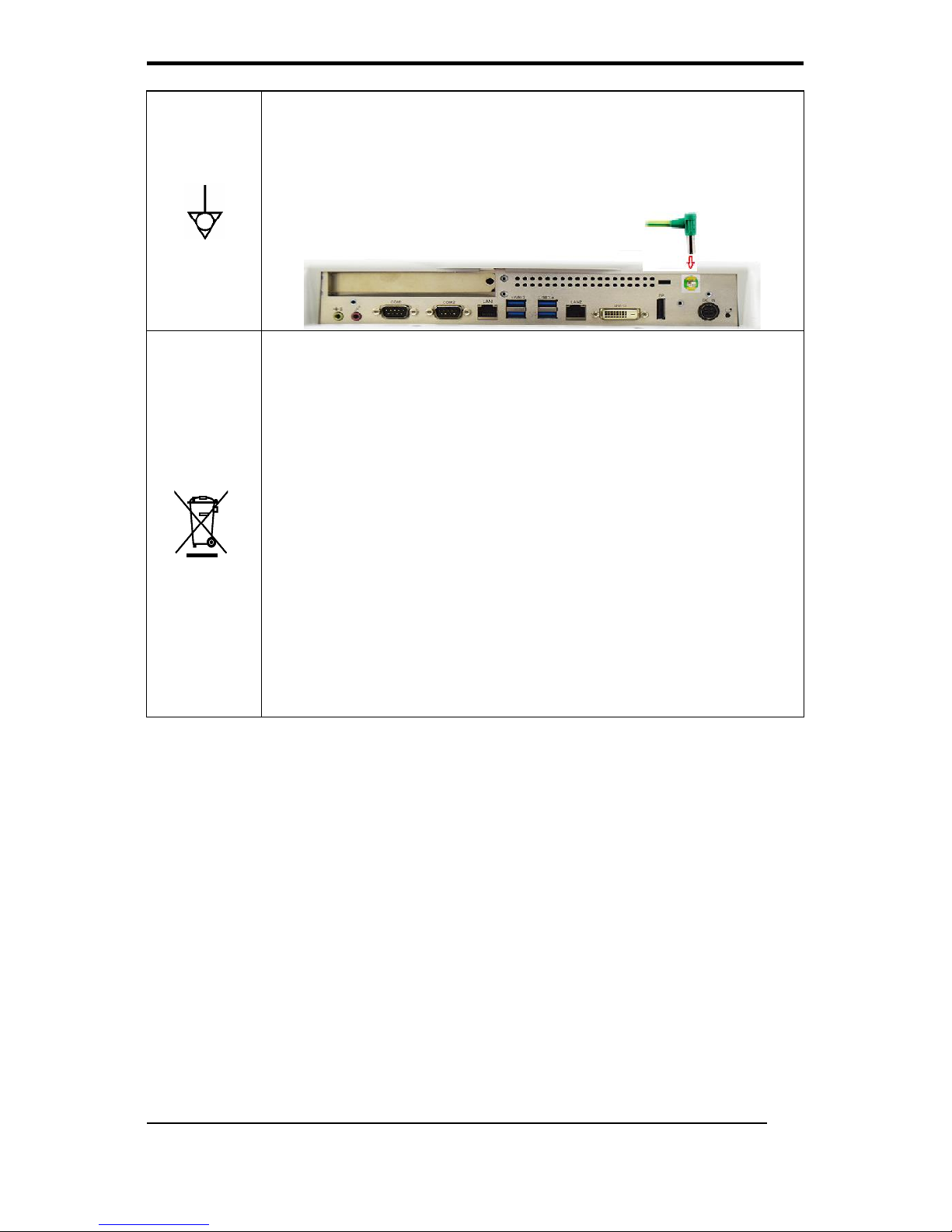
IEC 60417-5021: Equipotentiality. Connect device to
a potential equalization conductor.
- Potential Equalization Connector:
Panel PC is equipped with an equipotential connector.
EU-wide legislation, as implemented in each
Member State, requires that waste electrical and
electronic products carrying the mark (left) must be
disposed of separately from normal household
waste. This includes monitors and electrical
accessories, such as signal cables or power cords.
When you need to dispose of your display products,
please follow the guidance of your local authority, or
ask the shop where you purchased the product, or if
applicable, follow any agreements made between
yourself.
The mark on electrical and electronic products only
applies to the current European Union Member
States.
Page 11
WMP-17F User’s manual
xi
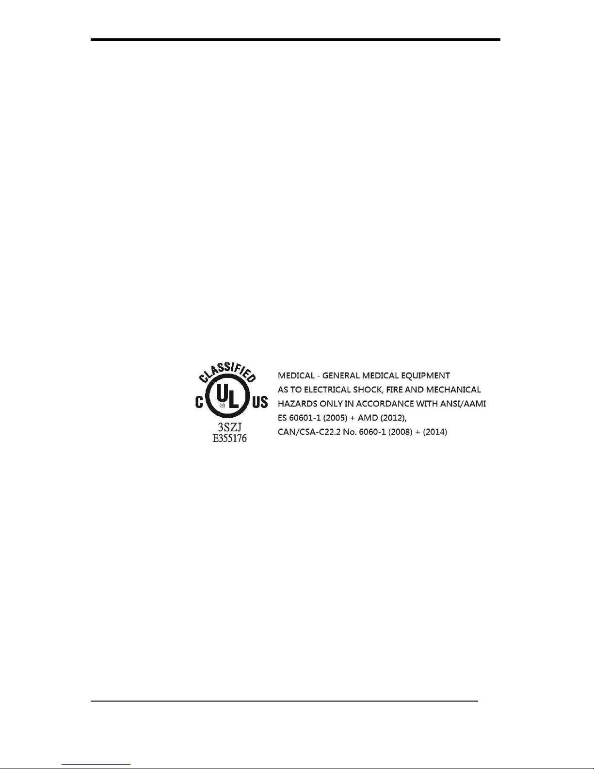
When networking with electrical devices, the operator is
responsible for ensuring that the resulting system meets the
requirements set forth by the following standards:
– EN 60601-1 (IEC 60601-1)
Medical electrical equipment
Part 1: General requirements for safety
– EN 60601-1-1 (IEC 60601-1-1)
Medical electrical equipment
Part 1-1: General requirements for safety
Collateral standard: Safety requirements for
Medical electrical systems
– EN 60601-1-2 (IEC 60601-1-2)
Medical electrical equipment
Part 1-2: General requirements for safety
Collateral standard: Electromagnetic compatibility;
Requirements and tests
Accessory
equipment
connected to
the analog
and digital
interfaces
must be in
compliance with the respective nationally harmonized IEC
standards (i.e. IEC 60950 for data processing equipment, IEC
60065 for video equipment, IEC 61010-1 for laboratory
equipment, and IEC 60601-1 for medical equipment.)
Furthermore all configurations shall comply with the system
standard IEC 60601-1-1. Everybody who connects additional
equipment to the signal input part or signal output part
configures a medical system, and is therefore, responsible that
the system complies with the requirements of the system
standard IEC 60601-1-1. The unit is for exclusive interconnection
with IEC 60601-1 certified equipment in the patient environment
and IEC 60XXX certified equipment outside of the patient
environment. If in doubt, consult the technical services
department or your local representative.
Page 12

WMP-17F User’s manual
xii
Caution:
DO NOT LEAVE THIS EQUIPMENT IN AN UNCONTROLLED
ENVIRONMENT WHERE THE STORAGE TEMPERATURE IS BELOW
-20° C (-4° F) OR ABOVE 60° C (140° F). THIS MAY DAMAGE THE
EQUIPMENT.
This equipment shall not be used in life support systems.
The user is not to touch SIP/SOPs and the patient at the same
time.
Caution – Use suitable mounting apparatus to avoid risk of injury.
Caution - Risk of explosion if battery is replaced by an incorrect
type. Dispose of used batteries according to the instructions.
The sound pressure level at the operator’s position according to
IEC 704-1:1982 is no more than 70dB (A).
A) Grounding reliability can only be achieved when the equipment
is connected to an equivalent receptacle marked “Hospital
Only” or “Hospital Grade”.
B) Use a power cord that matches the voltage of the power outlet,
which has been approved and complies with the safety
standard of your particular country.
C) Caution: This adapter Sinpro HPU101-105 is a forming part of
the medical device
Page 13

WMP-17F User’s manual
xiii
Contact information:
Wincomm Corporation
3F, No.14, Prosperity Road II, Science-Based Industrial Park,
Hsinchu, Taiwan 300, R.O.C
TEL: (886) 3 5780000
E-Mail: [email protected]
Page 14

WMP-17F User’s manual
xiv
Table of Contents
Acknowledgments ...................................... iii
FCC Class B ............................................... iv
Safety Instructions ...................................... v
Introduction ............................................ 1
Product Description ..................................... 1
Package list ................................................ 2
Features .................................................... 3
Specifications ............................................. 4
Guidance and manufacturer’s declaration –
electromagnetic emissions ........................... 6
Guidance and manufacturer’s declaration –
electromagnetic immunity ............................ 8
Immunity ................................................... 9
Cleaning/Disinfecting ................................. 11
Getting Started ...................................... 12
System Set Up .......................................... 12
Dimension ................................................ 13
System View ............................................ 14
Disconnect Device ..................................... 17
BIOS Setup ............................................ 18
Appendix ................................................ 32
A. Jumper settings and Connectors ............. 32
B. VESA Mounting (optional kit) .................. 55
C. Battery Pack Specifications (optional kit) .. 57
D. How to disable battery when system hang up
on WMP-17F ............................................. 58
E. Scrap Computer Recycling ...................... 59
Page 15

WMP-17F User’s manual
1
Introduction
Product Description
The WMP-17F Medical Panel PC are based on Intel 6th generation
Core i processor which can deliver faster graphic with higher CPU
performance. It accommodates one 2.5” SATA III hard disk drive
and up to 32GB DDR4 SODIMM.
The high brightness LCD, Low Noise solution, integrated
multimedia functions and extensive expansion options make
them the perfect platform upon which to build comprehensive
lifestyle computing applications.
The WMP-17F includes all the features of a powerful computer
into a slim and attractive chassis. The WMP-17F has a 17” high
brightness TFT display with 1280 x 1024 resolution. Integrating
with high brightness LCD is easier to analyze DICOM image.
The WMP-17F is compact, two Giga LAN and selectable WLAN
network compatible PC with full safety and medical approval and
features to control a dedicated system with a wide variety of
applications. Combining the WMP-17F into your system can
achieve both cost-saving and efficient improvements.
Common applications include LIS (Lab Information Systems) and
Electronic Medical Record. The WMP-17F are definitely your
perfect choices.
Page 16

WMP-17F User’s manual
2
Package list
Before you begin installing your Medical Station, please make
sure that the following items have been shipped:
The WMP-17F Medical Panel PC unit
User's manual, chipset drivers
Power Adapter x 1 (Mf:Sinpro, type/model: HPU101-105)
Power cord – Hospital grade used (US type), or other type in
UK, EU…etc.
Stylus pen x 1 (By configuration)
Screw x 8 (VESA 75/100 use)
Page 17

WMP-17F User’s manual
3
Features
Anti-bacteria coating (Against Escherichia coli &
Staphylococcus Aureus)
17" (1280X1024), 350 nits Diagnostic Panel
High performance 6
th
generation intel Core i CPU (S series),
35W max.
Supports Dual Channel DDR4 SODIMM up to 32GB
Low noise Smart fan solution
Two mini PCI-e expansion (One full size and one half size)
HDD Anti-vibration mechanism
Supports PCI-E x 16 (option)
Tempered glass as option
USB/LAN/COM isolated module by different configuration
(optional order configuration)
Optional battery pack, and desktop stand
Page 18

WMP-17F User’s manual
4
Specifications
[
Hardware Specifications
Display
17” 350 nits SXGA color TFT LCD
CPU Support
LGA1151 package 6th generation Intel®
Core i7/i5/Pentium processor (35W max.)
Disk Drive Space
2.5” Hard Disk Drive (SATA III)
Expansion
Two Mini PCIe slot (+3.3V loaded 300mA, total
loaded 1.98W; only for isolated version);
One PCI-E expansion slot (3.3V loaded 2A, total
loaded 6.6W)
Button
Brightness down/Brightness up // Power //
Volume down/Volume up
I/O
Standard version
RS-232 port *1 + RS-232/422/485 port *1
USB 3.0 port *4,
DC-in w/ lock function *1
Gigabit LAN RJ-45 Connectors *2
DP x 1 + DVI x 1
Sound:
Line-in *1
Line-out *1
2W Speaker *2
Optional: PCI or PCI-E slot x 1
Isolated version
RS-232 port *1 + RS-232/422/485 port *1
ISO-RS232 *1 + ISO-RS232/422/485 * 1
USB 3.0 port *4,
ISO USB2.0 * 1
DC-in w/ lock function *1
Gigabit LAN RJ-45 Connectors *2
ISO giga-LAN *1
DP x 1 + DVI x 1
Sound:
Line-in *1
Line-out *1
2W Speaker *2
Page 19
WMP-17F User’s manual
5
LCD Specifications
Model Name
G170EG01 (V0)
Display Type
17” color TFT LCD
Max. Resolution
1280 x 1024
Contrast Ratio
1000 : 1 (Typ)
Pixel Pitch (mm)
0.264 (per one triad) x 0.264
Luminance (cd/m2)
350 (TYP)
Viewing Angle
170°(H)
160°(V)
Operating Temperature
0°C~ 40°C (32°F~104°F)
Brightness Control
Yes
Cautions:
Continuous displaying fixed pattern may induce image sticking.
It’s recommended to use screen saver or moving content
periodically if fixed pattern is displayed on the screen.
Power Adapter Specifications
Power
Close-frame
MFR
Sinpro
Type
HPU101-105
Input Rating
AC 100 ~ 240 V, 1.2 – 0.5A @ 47 ~ 63 Hz
Output Rating
DC 12V, 8.33A
MTBF
100,000 hrs operation at 25°C
Classification
Power by Class I certified power adapter.
No applied part.
Mode of operation
Continuous operation
System input rating
DC 12V, 8.33A
Mechanical Specifications
Architecture
Close-frame
Front Bezel
PET bezel with resistive touch screen
Color
Medical-white
Mounting / Holder
VESA 75/100mm
Construction
3mm ABS + PC TYPE Plastic housing
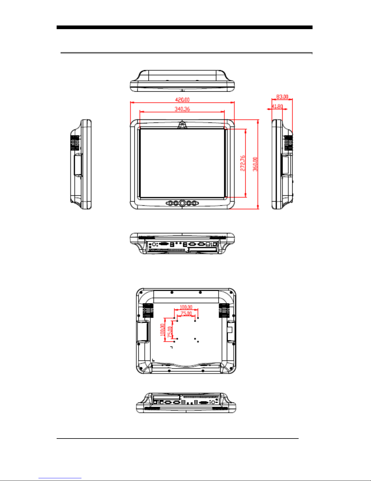
Dimension (WxHxD)
420mmx 360mm x 83 mm
Net Weight
6.5kg (w/o power adapter)
Packing Filler
PE
Page 20
WMP-17F User’s manual
6
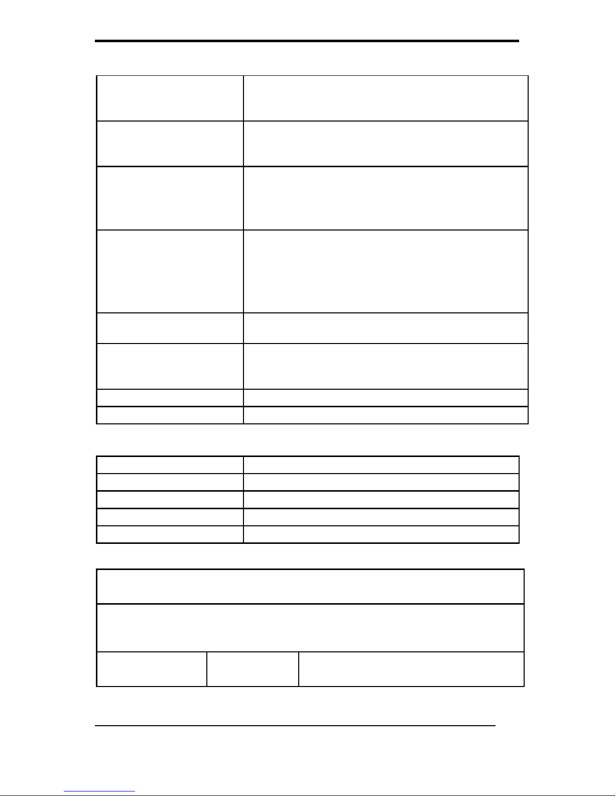
Environmental Specifications
Temperature
Operating: 0°C to 40°C (32°F ~104°F)
Storage, Transportation: -20°C to 60°C (-4°F
~140°F)
Humidity
Operating: 10% to 90%, non-condensing
Storage, Transportation: 10% to 90%@ 40°C,
non-condensing
Vibration
Operating: 15g/0.53 oz, 11 ms, half sine
wave
Non-operating: 50g/1.76 oz, 11 ms, half
sine wave
Shock
Operating: 5 ~ 17 Hz ,
Amplitude:0.117 ~ 500Hz ,
Acceleration:1.0G
Non-operating:10~55Hz/0.15g,
55~500Hz/2.0g
Altitudes
Operational: up to 3000 m (9842 feet)
Shipping: up to 12192 m (40000 feet)
Pressure
700 – 1060 hPa (Operation)
186 – 1060 hPa (Storage)
186 – 1060 hPa (Transportation)
EMI / Safety
CE / FCC / VCCI Class B/UL 60601-1/EN 60601-1
Noise
Fanless
Touch Screen
Type
5-wire, Analog Resistive
Interface
USB interface
Resolution
2048 x 2048
Light Transmission
80% ± 3%
Life Time
35 million activations
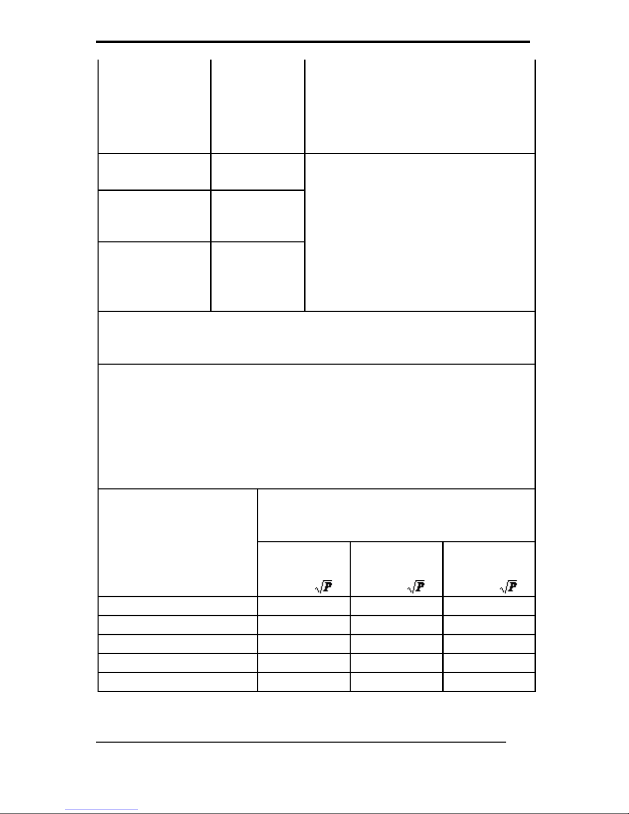
Guidance and manufacturer’s declaration – electromagnetic
emissions
The model WMP-17F is intended for use in the electromagnetic
environment specified below. The customer or the user of the model
WMP-17F should assure that it is used in such an environment.
Emissions test
Compliance
Electromagnetic environment –
guidance
Page 21
WMP-17F User’s manual
7
RF emissions
CISPR 11
The model WMP-17F uses RF
energy only for its internal function.
Therefore, its RF emissions are very
low and are not likely to cause any
interference in nearby electronic
equipment.
RF emissions
CISPR 11
The model WMP-17F is suitable for
use in all establishments, including
domestic establishments and those
directly connected to the public
low-voltage power supply network
that supplies buildings used for
domestic purposes.
Harmonic
emissions
IEC 61000-3-2
Voltage
fluctuations/
flicker emissions
IEC 61000-3-3
Recommended separation distances between
portable and mobile RF communications equipment and the model
WMP-17F
The model WMP-17F is intended for use in an electromagnetic
environment in which radiated RF disturbances are controlled. The
customer or the user of the model WMP-17F can help prevent
electromagnetic interference by maintaining a minimum distance
between portable and mobile RF communications equipment
(transmitters) and the model WMP-17F as recommended below,
according to the maximum output power of the communications
equipment.
Rated maximum
output power of
transmitter
W
Separation distance according to
frequency of transmitter
m
150 kHz to
80 MHz
d = 1,2
80 MHz to
800 MHz
d = 1,2
800 MHz to
2,5 GHz
d = 2,3
0,01
0,12
0,12
0,23
0,1
0,38
0,38
0,73
1
1,2
1,2
2,3
10
3,8
3,8
7,3
100
12
12
23
Page 22

WMP-17F User’s manual
8
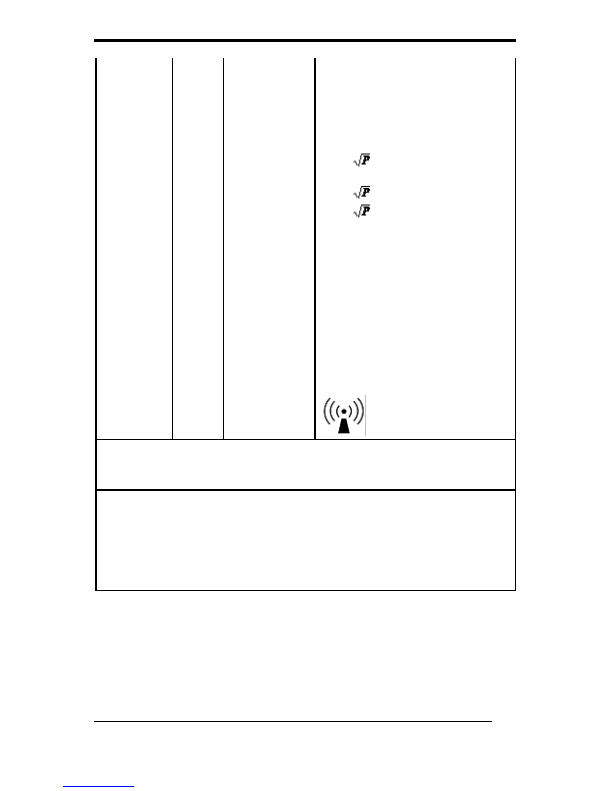
For transmitters rated at a maximum output power not listed above, the
recommended separation distanced in meters (m) can be estimated
using the equation applicable to the frequency of the transmitter, where P
is the maximum output power rating of the transmitter in watts (W)
according to the transmitter manufacturer.
NOTE 1 At 80 MHz and 800 MHz, the separation distance for the higher
frequency range applies.
NOTE 2 These guidelines may not apply in all situations. Electromagnetic
propagation is affected by absorption and reflection from structures,
objects and people.
Guidance and manufacturer’s declaration – electromagnetic
immunity
The model WMP-17F is intended for use in the electromagnetic
environment specified below. The customer or the user of the model
WMP-17F should assure that it is used in such an environment.
Immunity test
IEC 60601
test level
Compliance
level
Electromagnetic
environment –
guidance
Electrostatic
discharge
(ESD)
IEC 61000-4-2
6 kV contact
8 kV air
6 kV contact
8 kV air
Floors should be
wood, concrete or
ceramic tile. If floors
are covered with
synthetic material, the
relative humidity
should be at least 30
%.
Electrical fast
transient/burst
IEC 61000-4-4
2 kV for
power
supply lines
1 kV for
input/output
lines
2 kV for
power
supply lines
1 kV for
input/output
lines
Mains power quality
should be that of a
typical commercial or
hospital environment.
Surge
IEC 61000-4-5
1 kV line(s)
to line(s)
2 kV line(s)
to earth
1 kV line(s)
to line(s)
2 kV line(s)
to earth
Mains power quality
should be that of a
typical commercial or
hospital environment.
Page 23

WMP-17F User’s manual
9
interruptions
and
voltage
variations
on power
supply
input lines
IEC
61000-4-11
<5 % UT
(>95 % dip in
UT)
for 0,5 cycle
40 % UT
(60 % dip in
UT)
for 5 cycles
70 % UT
(30 % dip in
UT)
for 25 cycles
<5 % UT
(>95 % dip in
UT)
for 5 sec
<5 % UT
(>95 % dip in
UT)
for 0,5 cycle
40 % UT
(60 % dip in
UT)
for 5 cycles
70 % UT
(30 % dip in
UT)
for 25 cycles
<5 % UT
(>95 % dip in
UT)
for 5 sec
Mains power quality
should be that of a
typical commercial or
hospital environment.
If the user of the
model WMP-17F
requires continued
operation during
power
mains interruptions, it
is recommended that
the model WMP-17F
be powered from an
uninterruptible power
supply or a battery.
Power
frequency
(50/60 Hz)
magnetic field
IEC 61000-4-8
3 A/m
3 A/m
Power frequency
magnetic fields
should be at levels
characteristic of a
typical location in a
typical commercial or
hospital environment.
NOTE UT is the a.c. mains voltage prior to application of the test level.
Guidance and manufacturer’s declaration – electromagnetic immunity
The model WMP-17F is intended for use in the electromagnetic environment specified below. The
customer or the user of the model WMP-17F should assure that it is used in such an environment.
Immunity
IEC
60601
test level
Compliance
level
Electromagnetic environment – guidance
Page 24
WMP-17F User’s manual
10
Conducted RF
IEC 61000-4-6
Radiated RF
IEC 61000-4-3
3 Vrms
150 kHz
to 80
MHz
3 V/m
80 MHz
to 2,5
GHz
Vrms
V/m
Portable and mobile RF communications
equipment should be used no closer to any part
of the model WMP-17F, including cables, than
the recommended separation distance
calculated from the equation applicable to the
frequency of the transmitter.
Recommended separation distance
d = 1,2
d = 1,2 80 MHz to 800 MHz
d = 2,3 800 MHz to 2,5 GHz
where P is the maximum output power rating of
the transmitter in watts (W) according to the
transmitter manufacturer and d is the
recommended separation distance in meters
(m).
Field strengths from fixed RF transmitters, as
determined by an electromagnetic site survey, a
should be less than the compliance level in
each frequency range. b
Interference may occur in the vicinity of
equipment marked with the following symbol:
NOTE 1 At 80 MHz and 800 MHz, the higher frequency range applies.
NOTE 2 These guidelines may not apply in all situations. Electromagnetic propagation is affected by
absorption
and reflection from structures, objects and people.
a
Field strengths from fixed transmitters, such as base stations for radio (cellular/cordless) telephones
and land mobile radios, amateur radio, AM and FM radio broadcast and TV broadcast cannot be
predicted theoretically with accuracy. To assess the electromagnetic environment due to fixed RF
transmitters, an electromagnetic site survey should be considered. If the measured field strength in
the location in which the model WMP-17F is used exceeds the applicable RF compliance level above,
the model WMP-17F should be observed to verify normal operation. If abnormal performance is
observed, additional measures may be necessary, such as reorienting or relocating the model
WMP-17F.
b
Over the frequency range 150 kHz to 80 MHz, field strengths should be less than V/m.
Page 25

WMP-17F User’s manual
11
Cleaning/Disinfecting
Steps:
1. Wipe the WMP-17F with a dry clean cloth.
2. Operate with manufacturer’s instructions or hospital protocol.
Cautions:
Do not immerse or rinse the WMP-17F and its peripherals. If
you accidentally spill liquid on the device, disconnect the
unit from the power source. Contact your Biomed regarding
the continued safety of the unit before placing it back in
operation.
Do not spray cleaning agent on the chassis.
Do not use disinfectants that contain phenol.
Do not autoclave or clean the WMP-17F or its peripherals
with strong aromatic, chlorinated, ketone, ether, or Esther
solvents, sharp tools or abrasives. Never immerse electrical
connectors in water or other liquids.
Page 26

WMP-17F User’s manual
12
Getting Started
System Set Up
The following is a summary of the steps in setting up the system
for use.
(1). You can fix the system to a mounting fixture using the screw
holes on the sides of the system.
(2). Make any required external connections such as the display,
keyboard, and LAN.
(3). Plug the appropriate end of the power cord into the power
connector on the rear of the system and the plug to an
electrical outlet.
(4). Waiting for 3 seconds then press the power switch on the
front panel of the system once to turn on the system power.
(5). If necessary, run the BIOS SETUP programs to configure the
system.
Caution:
In order to boot up system from USB-CD/DVD drive,
please connect USB-CD/DVD drive, turn on computer
power, keep on pressing “F11” key, go into BIOS quick
boot menu, select “USB-CD ROM”, WAIT FOR 20
SECONDS, then press enter, system OS will boot up
from USB-CD/DVD drive directly.
Notice:
The installation is only to be carried out by
manufacturer trained and authorized personnel.
Page 27
WMP-17F User’s manual
13
Dimension
Page 28
WMP-17F User’s manual
14
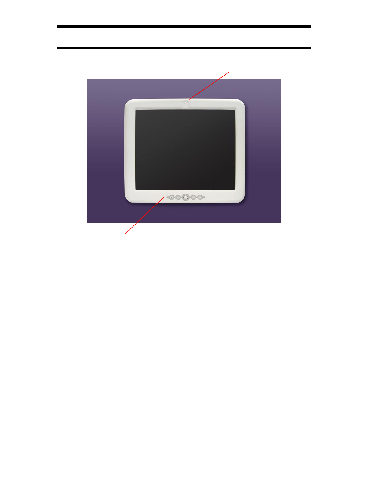
System View
Front View
Control button at front panel
From left to right:
1. Brightness down
2. Brightness up
3. Power
4. Volume down
5. Volume up
Webcam (optional)
Page 29

WMP-17F User’s manual
15
Rear View
VESA 75/100
Page 30
WMP-17F User’s manual
16
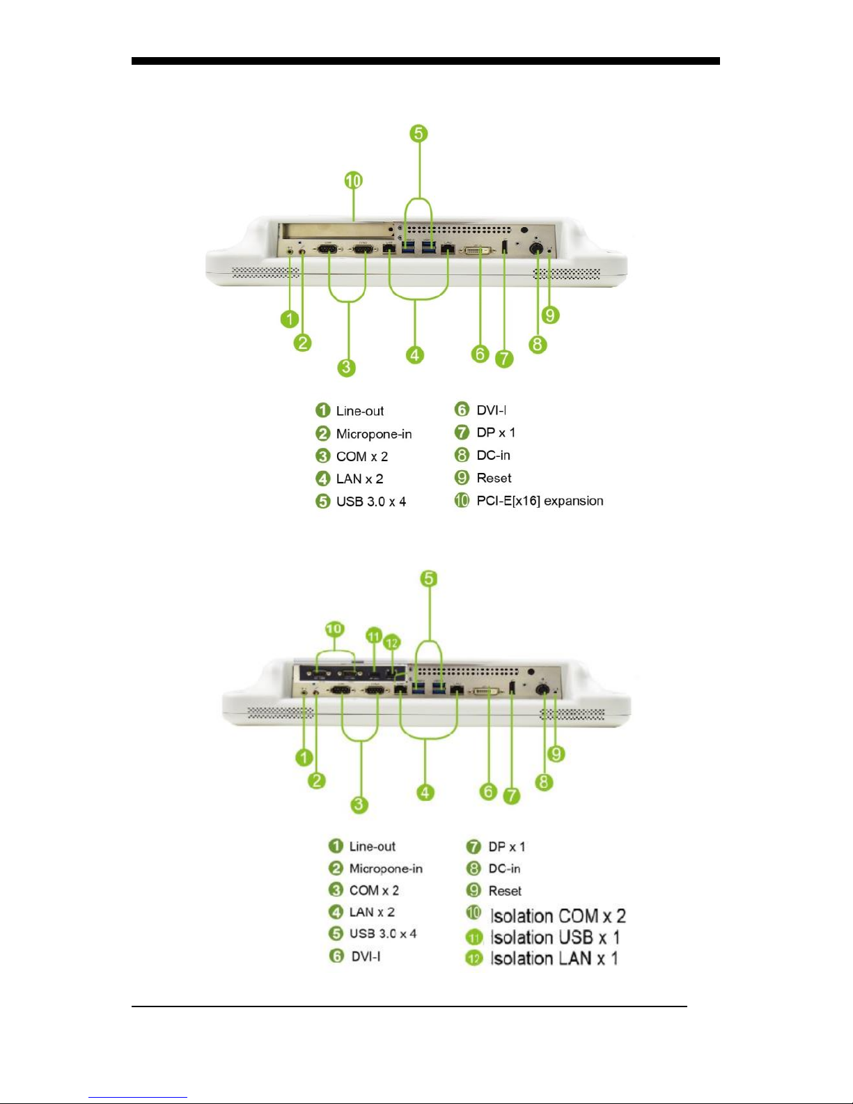
I/O parts (WMP-17F-STD)
I/O parts (WMP-17F-ISO)
Page 31
WMP-17F User’s manual
17
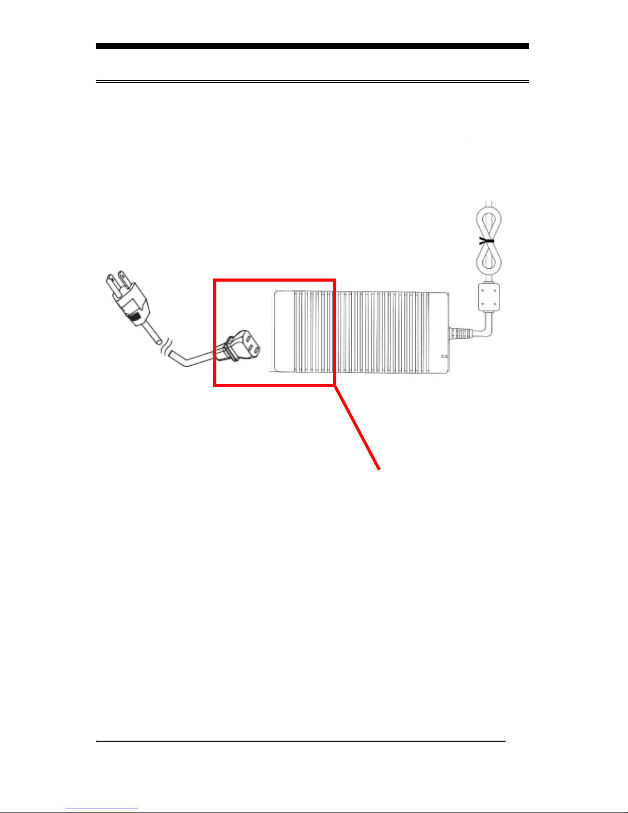
Disconnect Device
Unplug the power cord from the power
adapter jack to disconnect the device.
Page 32

WMP-17F User’s manual
18
BIOS Setup
BIOS Introduction
The AMI BIOS (Basic Input / Output System) installed in your
computer system’s ROM supports Intel processors. The BIOS
provides critical low-level support for a standard device such as
disk drives, serial ports and parallel ports. It also adds virus and
password protection as well as special support for detailed
fine-tuning of the chipset controlling the entire system.
BIOS Setup
The AMI BIOS provides a Setup utility program for specifying the
system configurations and settings. The BIOS ROM of the system
stores the Setup utility. When you turn on the computer, the AMI
BIOS is immediately activated. Pressing the <Del> key
immediately allows you to enter the Setup utility. If you are a
little bit late pressing the <Del> key, POST (Power On Self Test)
will continue with its test routines, thus preventing you from
invoking the Setup. If you still wish to enter Setup, restart the
system by pressing the ”Reset” button or simultaneously pressing
the <Ctrl>, <Alt> and <Delete> keys. You can also restart by
turning the system Off and back On again. The following message
will appear on the screen:
Press <DEL> to Enter Setup
In general, you press the arrow keys to highlight items, <Enter>
to select, the <PgUp> and <PgDn> keys to change entries, <F1>
for help and <Esc> to quit.
When you enter the Setup utility, the Main Menu screen will
appear on the screen. The Main Menu allows you to select from
various setup functions and exit choices.
Page 33

WMP-17F User’s manual
19
Main
This section provides information on the BIOS information, Memory information, and Battery information
System Date
Set the system date. Use the <Tab> key to switch between data
elements.
System Time
Set the system time. Use the <Tab> key to switch between time
elements.
Page 34
WMP-17F User’s manual
20
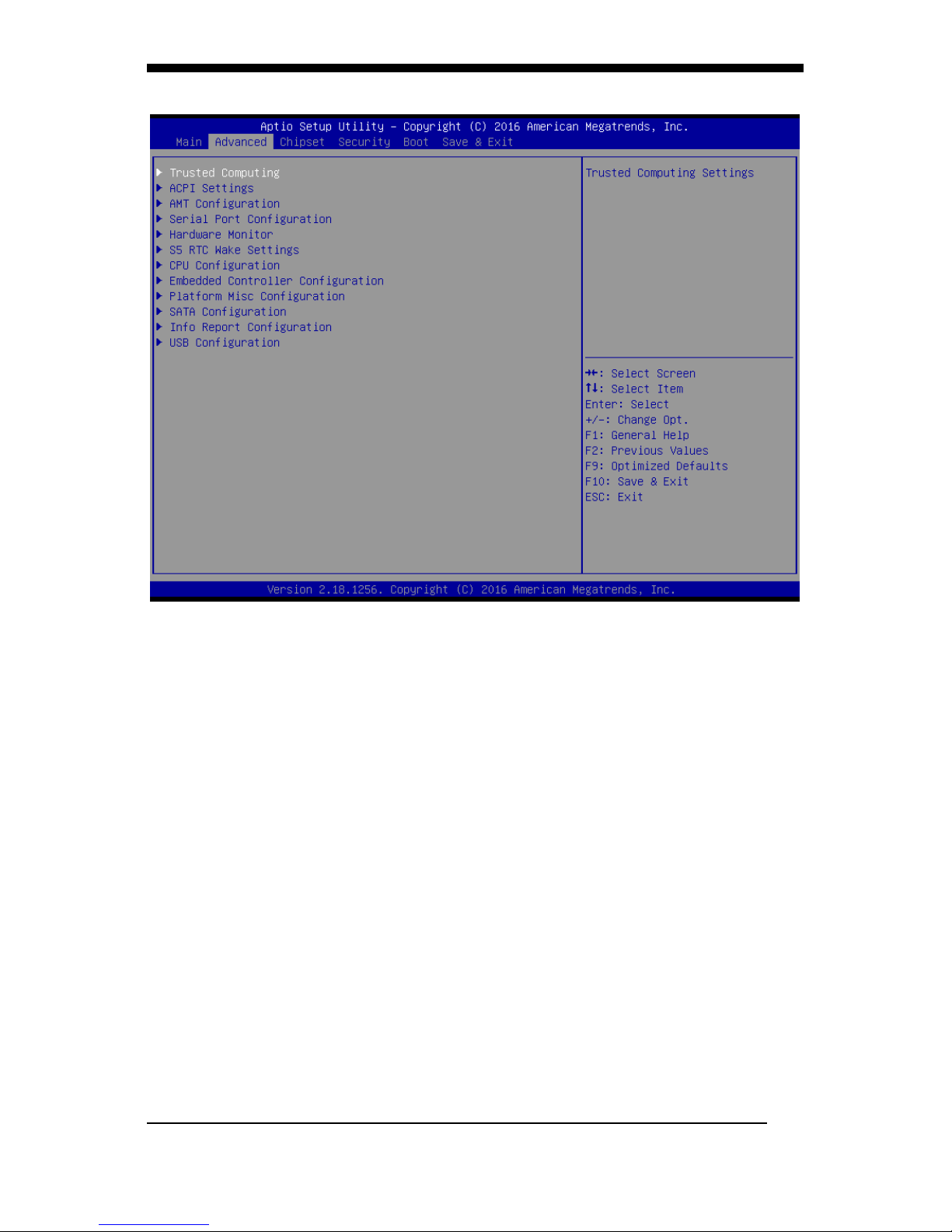
Advanced
Trusted Computing
Security Device Support
Enables or Disables BIOS support for security
device. O.S. will not show Security Device. TCG EFI
protocol and INT1A interface will not be available.
ACPI Settings
Enable Hibernation
Enables or Disables System ability to Hibernate
(OS/S4 Sleep State). This option may be not
effective with some OS.
ACPI Sleep State
Select the highest ACPI sleep state the system will
enter when the SUSPEND button is pressed.
AMT Configuration
Intel AMT
Enable/Disable Intel (R) Active Management
Technology BIOS Extension.
Note : iAMT H/W is always enabled.
This option just controls the BIOS extension
execution.
Page 35

WMP-17F User’s manual
21
If enabled, this requires additional firmware in the
SPI device
BIOS Hotkey Pressed
OEMFLag Bit 1:
Enable/Disable BIOS hotkey press.
MEBx Selection Screen
OEMFLag Bit 2:
Enable/Disable MEBx selection screen.
Hide Un-Configure ME Confirmation Prompt
OEMFlag Bit 6:
Hide Un-Configure ME without password
Confirmation Prompt
Un-Configure ME
OEMFlag Bit 15:
Un-Configure ME without password.
Serial Port Configuration
Serial Port 1 Configuration
Set Parameters of Serial Port 1 (COMA)..
Serial Port 2 Configuration
Set Parameters of Serial Port 2 (COMB).
Serial Port 3 Configuration
Set Parameters of Serial Port 3 (COMC).
Serial Port 4 Configuration
Set Parameters of Serial Port 4 (COMD).
Serial Port 5 Configuration
Set Parameters of Serial Port 5 (COME).
Serial Port 6 Configuration
Set Parameters of Serial Port 6 (COMF).
Hardware Monitor
CPU Fan Control Mode
Select CPU Fan Control Mode
CPU FAN Boundary Hystersis
Boundary hysteresis. (0~15ºC). Segment will change
when the temperature is over the boundary
temperature and below the boundary deducts the
hysteresis temperature.
CPU TEMPERATURE BOUNDARY 1
CPU TEMPERATURE BOUNDARY 1
CPU TEMPERATURE BOUNDARY 2
CPU TEMPERATURE BOUNDARY 2
CPU TEMPERATURE BOUNDARY 3
CPU TEMPERATURE BOUNDARY 3
Page 36

WMP-17F User’s manual
22
CPU TEMPERATURE BOUNDARY 4
CPU TEMPERATURE BOUNDARY 4
CPU Fan Duty Cycle 1 (%)
CPU Fan Duty Cycle 1 (%)
CPU Fan Duty Cycle 2 (%)
CPU Fan Duty Cycle 2 (%)
CPU Fan Duty Cycle 3 (%)
CPU Fan Duty Cycle 3 (%)
CPU Fan Duty Cycle 4 (%)
CPU Fan Duty Cycle 4 (%)
CPU Fan Duty Cycle 5 (%)
CPU Fan Duty Cycle 5 (%)
System Fan Control Mode
Select System Fan Control Mode
System FAN Boundary Hystersis
Boundary hysteresis. (0~15ºC). Segment will change
when the temperature is over the boundary
temperature and below the boundary deducts the
hysteresis temperature.
System TEMPERATURE BOUNDARY 1
System TEMPERATURE BOUNDARY 1
System TEMPERATURE BOUNDARY 2
System TEMPERATURE BOUNDARY 2
System TEMPERATURE BOUNDARY 3
System TEMPERATURE BOUNDARY 3
System TEMPERATURE BOUNDARY 4
System TEMPERATURE BOUNDARY 4
System Fan Duty Cycle 1 (%)
System Fan Duty Cycle 1 (%)
System Fan Duty Cycle 2 (%)
System Fan Duty Cycle 2 (%)
System Fan Duty Cycle 3 (%)
System Fan Duty Cycle 3 (%)
System Fan Duty Cycle 4 (%)
System Fan Duty Cycle 4 (%)
System Fan Duty Cycle 5 (%)
System Fan Duty Cycle 5 (%)
S5 RTC Wake Settings
Wake system from S5
Enable or disable System wake on alarm event.
Select FixedTime, system will wake on the
Page 37

WMP-17F User’s manual
23
hr::min::sec specified. Select DynamicTime , System
will wake on the current time + Increase minute(s)
CPU Configuration
Hyper-threading
Enabled for Windows XP and Linux (OS optimized for
Hyper-Threading Technology) and Disabled for other
OS (OS not optimized for Hyper-Threading
Technology). When Disabled only one thread per
enabled core is enabled.
Active Processor Cores
Number of cores to enable in each processor
package.
Intel Virtualization Technology
When enabled, a VMM can utilize the additional
hardware capabilities provided by Vanderpool
Technology
Intel(R) SpeedStep(tm)
Allows more than two frequency ranges to be
supported.
Turbo Mode
Turbo Mode.
Battery Mode Power Limit
Enable/Disable battery mode power limit function
Embedded Controller Configuration
Battery Off Time
Number of seconds of cut off battery ouput after
system shutdowns.
0~600 second(s)
0 means disable battery off function.
Platform Misc Configuration
Native PCIE Enable
PCI Express Native Support Enable/Disable. This
feature is only available in Vista.
Native ASPM
On enable, Vista will control the ASPM support for the
device. If disabled, the BIOS will.
Show/hide hidden items
For debug only.
Show / hide hidden items.
SATA Configuration
SATA Controller(s)
Enable or disable SATA Device.
Page 38

WMP-17F User’s manual
24
SATA Mode Selection
Determines how SATA controller(s) operate.
Software Feature Mask Configuration
RAID OROM/RST driver will refer to the SWFM
configuration to enable or disable the storage
features.
Port 2-4
Enable or Disable SATA Port
Hot Plug
Designates this port as Hot Pluggable.
External SATA
External SATA Support.
Spin Up Device
On an edge detect from 0 to 1, the PCH starts a
COMRESET initialization sequence to the device.
SATA Device Type
Identify the SATA port is connected to Solid State
Drive or Hard Disk Drive.
Topology
Identify the SATA Topology if it is Default or ISATA or
Flex or DirectConnect or M2
Device Sleep
mSata for RTD3
SATA DEVSLEP Idle Timeout Config
Enable/Disable SATA DTIO Config
Info Report Configuration
Post Report
Post Report Support Enabled/Disabled
Info Error Message
Info Error Message Support Enabled/Disabled
Summary Screen
Summary Screen Support Enabled/Disabled
USB Configuration
Legacy USB Support
Enables Legacy USB support. AUTO option disables
legacy support if no USB devices are connected.
DISABLE option will keep USB devices available only
for EFI applications.
XHCI Hand-off
This is a workaround for OSes without XHCI hand-off
support. The XHCI ownership change should be
claimed by XHCI driver.
Page 39

WMP-17F User’s manual
25
USB Mass Storage Driver Support
Enable/Disable USB Mass Storage Driver Support.
Port 60/64 Emulation
Enables I/O port 60h/64h emulation support. This
should be enabled for the complete USB keyboard
legacy support for non-USB aware OSes.
USB transfer time-out
The time-out value for Control, Bulk, and Interrupt
transfers.
Device reset time-out
USB mass storage device Start Unit command
time-out.
Device power-up delay
Maximum time the device will take before it properly
reports itself to the Host Controller. 'Auto' uses default
value: for a Root port it is 100 ms, for a Hub port the
delay is taken from Hub descriptor.
Page 40
WMP-17F User’s manual
26
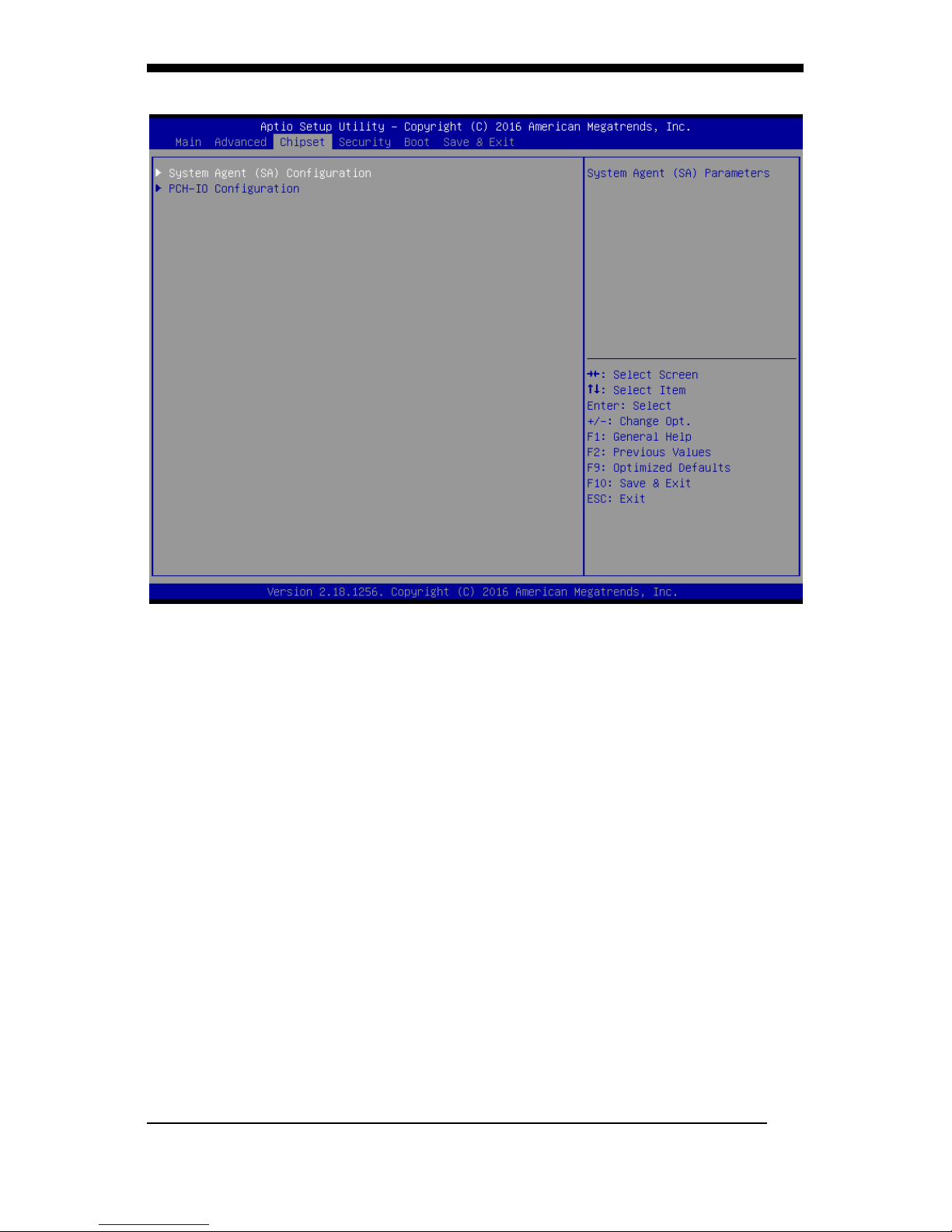
Chipset
System Agent (SA) Configuration
VT-d
VT-d capability
Graphics Configuration
Graphics Turbo IMON Current
Graphics turbo IMON current values supported
(14-31)
Skip Scaning of External Gfx Card
If Enable, it will not scan for External Gfx Card on
PEG and PCH PCIE Ports
Primary Display
Select which of IGFX/PEG/PCI Graphics device
should be Primary Display Or select SG for
Switchable Gfx.
Internal Graphics
Keep IGFX enabled based on the setup options.
GTT Size
Select the GTT Size
Aperture Size
Select the Aperture Size
Page 41

WMP-17F User’s manual
27
Note : Above 4GB MMIO BIOS assignment is
automatically enabled when selecting 2048MB
aperture. To use this feature, please disable CSM
Support.
DVMT Pre-Allocated
Select DVMT 5.0 Pre-Allocated (Fixed) Graphics
Memory size used by the Internal Graphics
Device.
DVMT Total Gfx Mem
Select DVMT5.0 Total Graphic Memory size used
by the Internal Graphics Device.
Memory Configuration
Memory Configuration Parameters
PCH-IO Configuration
PCI Express Configuration
PCI Express Clock Gating
Enable or disable PCI Express Clock Gating for
each root port.
USB Configuration
USB Precondition
Precondition work on USB host controller and
root ports for faster enumeration.
XHCI Disable Compliance Mode
Options to disable Compliance Mode. Default is
FALSE to not disable Compliance Mode. Set TRUE
to disable Compliance Mode.
USB Port Disable Override
Selectively Enable/Disable the corresponding
USB port from reporting a Device Connection to
the controller.
HD Audio
Control Detection of the HD-Audio device.
Disabled = HDA will be unconditionally disabled
Enabled = HDA will be unconditionally enabled
Auto = HDA will be enabled if present, disabled
otherwise.
PCH LAN Controller
Enable or disable onboard NIC.
DeepSx Power Policies
Configure the DeepSx Mode configuration.
LAN Wake From DeepSx
Page 42

WMP-17F User’s manual
28
Wake from DeepSx by the assertion of LAN_WAKE#
pin.
Wake on LAN
Enable or disable integrated LAN to wake the system.
(The Wake On LAN cannot be disabled if ME is on at
Sx state.)
SLP_LAN# Low on DC Power
Enable/Disable SLP_LAN# Low on DC Power.
Wake on WLAN Enable
Enable/Disable PCI Express Wireless LAN to wake the
system.
Restore AC Power Loss
Specify what state to go to when power is re-applied
after a power failure (G3 state).
Page 43
WMP-17F User’s manual
29
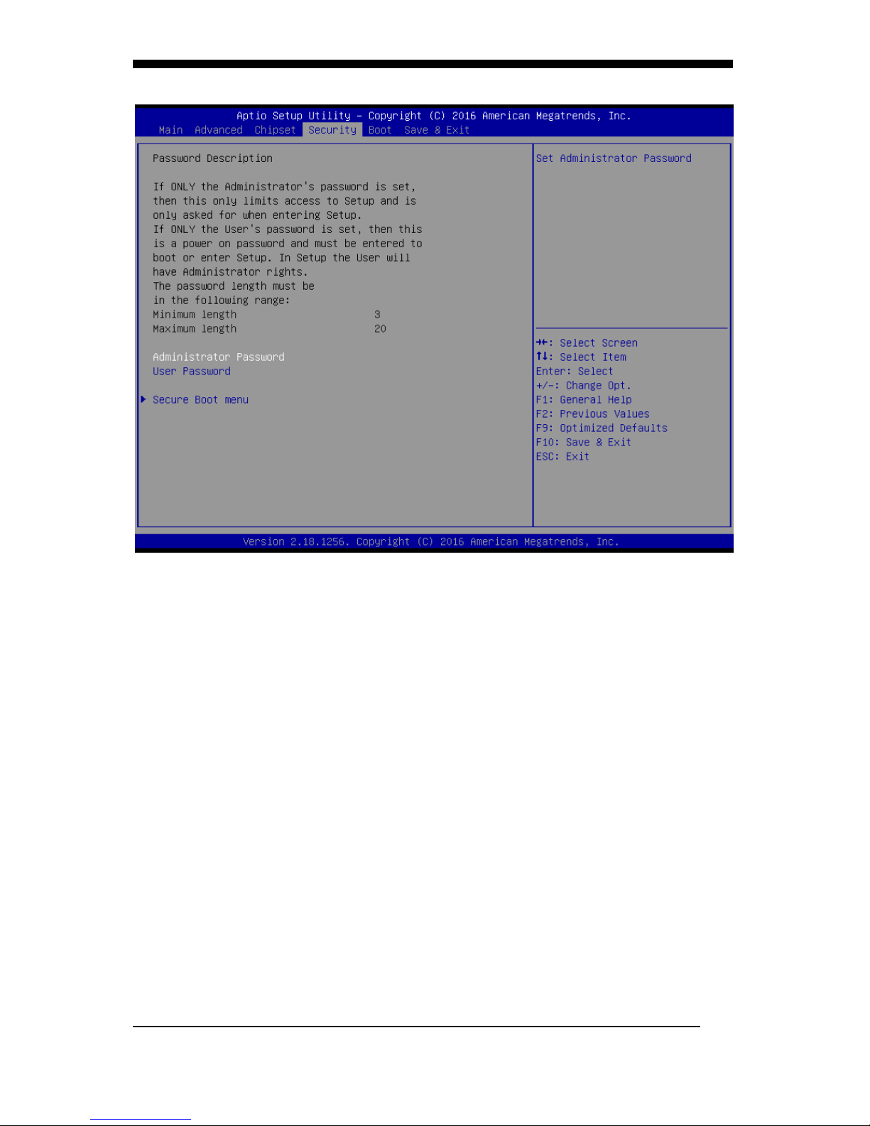
Security
Enables or disables the security chip. It is recommended that you
use this function with the Administrator/User password.
Page 44
WMP-17F User’s manual
30
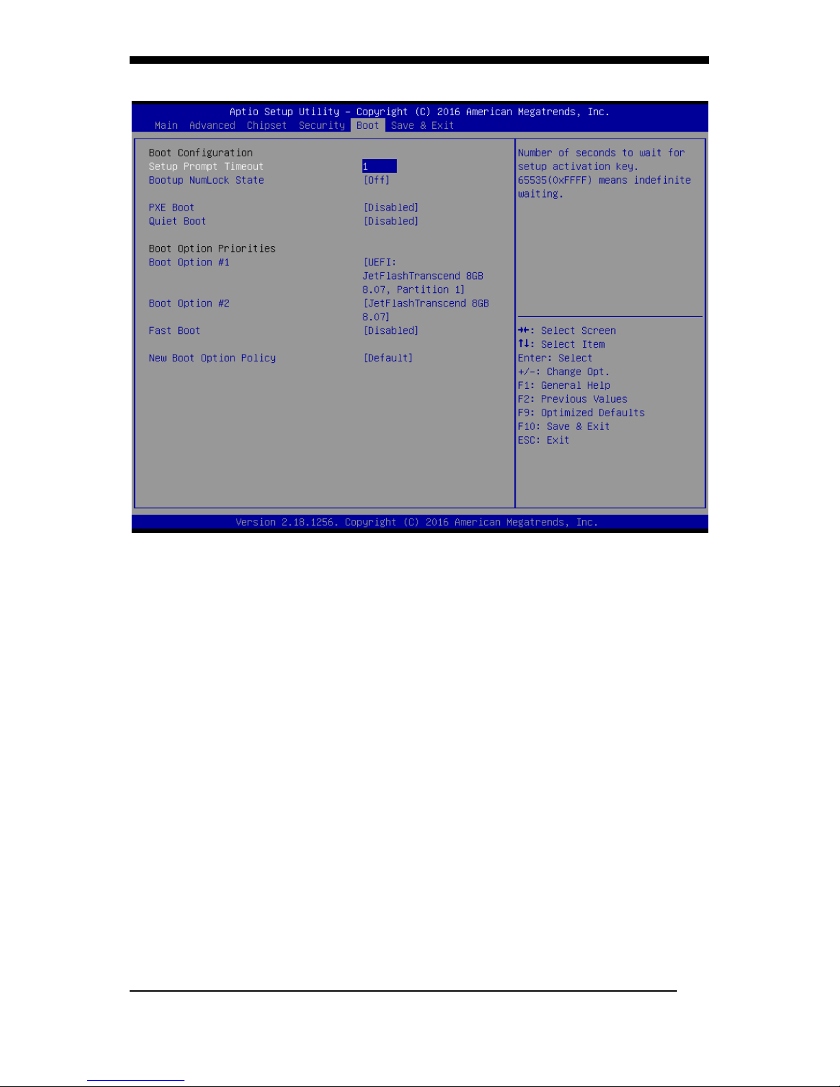
Boot
Setup Prompt Timeout
Number of seconds to wait for setup activation key.
65535(0xFFFF) means indefinite waiting.
Bootup Numlock State
Selects the keyboard NumLock state.
PXE Boot
PXE Network Boot Enable/Disable.
Quiet Boot
Allows you to determine whether to display the AMI Logo at
system startup. Disabled displays normal POST message.
Fast Boot
Enables or disables the quick boot function to speed up the
system boot-up process to shorten the waiting time for entering
the operating system and to deliver greater efficiency for daily
use.
New Boot Option Policy
Controls the placement of newly detected UEFI boot options the
installed hard drives.
Page 45
WMP-17F User’s manual
31
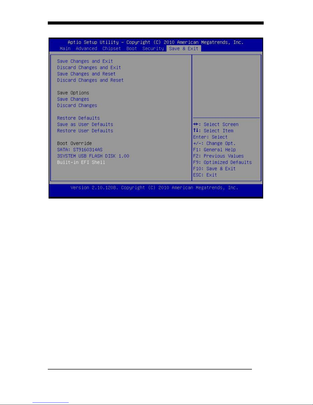
Save & Exit
Save Changes and Exit
Exit system setup after saving the changes.
Discard Changes and Exit
Exit system setup without saving any changes.
Save Changes and Reset
Reset the system after saving the changes.
Discard Changes and Reset
Reset system setup without saving the changes.
Save Changes
Save the changes done so far to any of setup options.
Discard Changes
Discard the changes done so far to any of setup options.
Restore Defaults
Restore/load default values for all the setup options.
Save as User Defaults
Save the changes done so far as User Defaults.
Restore User Defaults
Restore the User Defaults to all the setup options.
Launch EFI Shell from filesystem device
Attempts to Launch EFI Shell application (Shell.efi) from one of
the available filesystem devices.
Page 46
APPENDIX
WMP-17F User’s manual
32
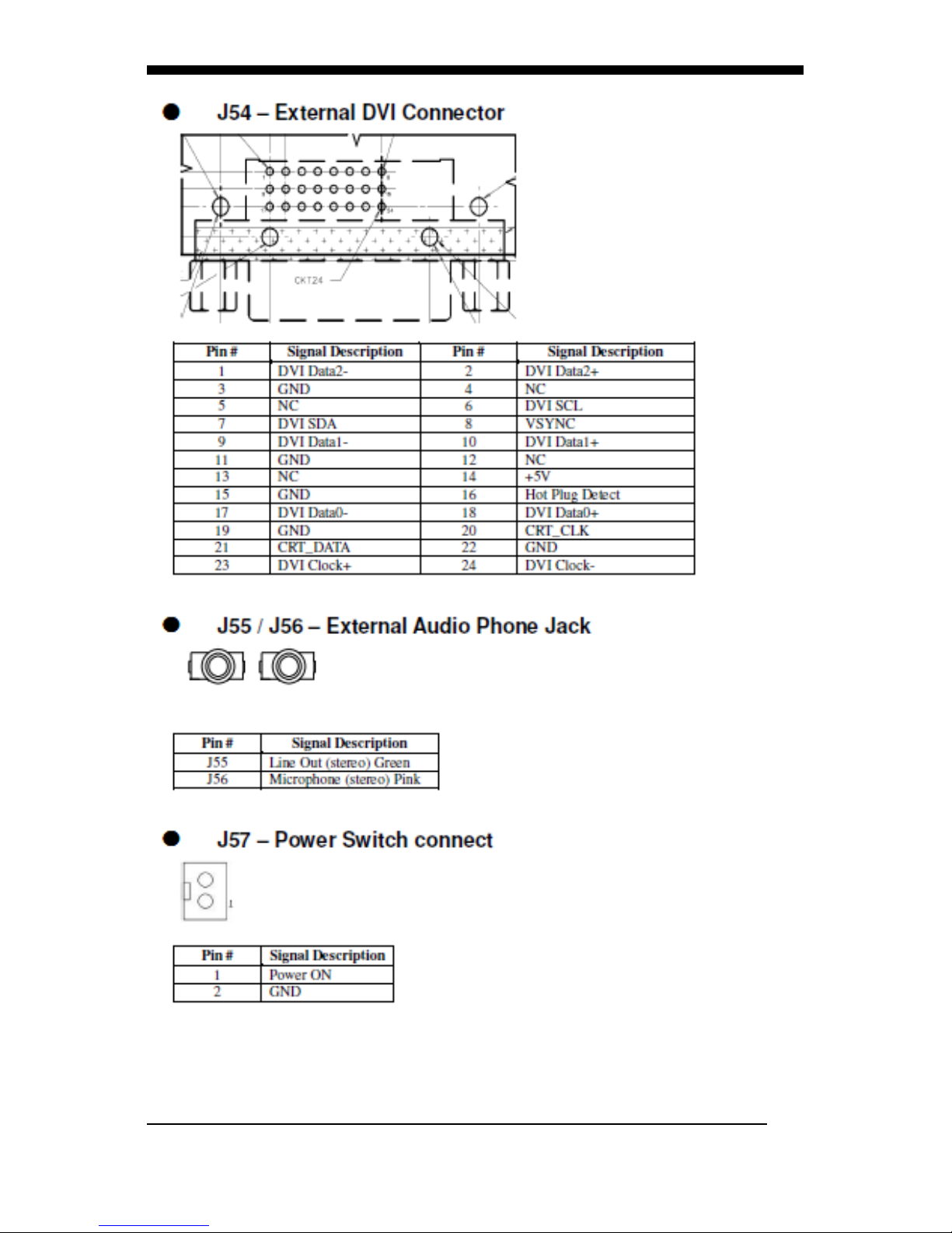
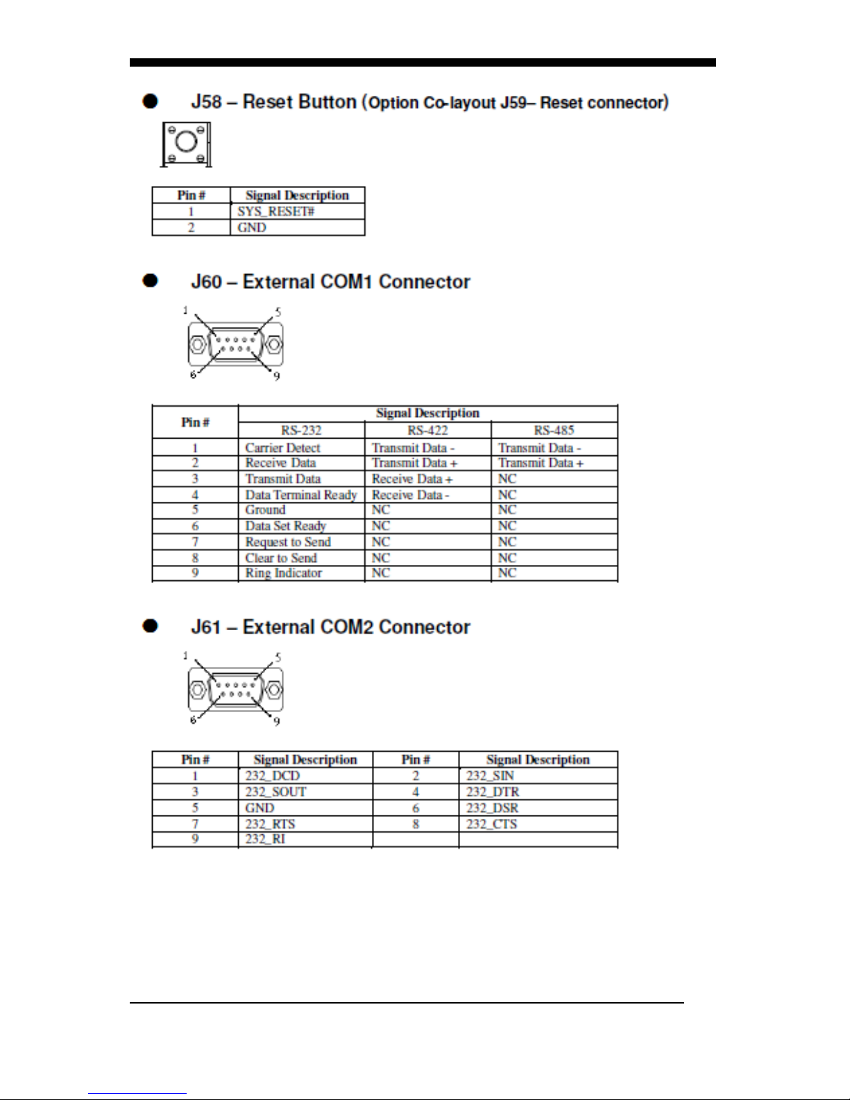
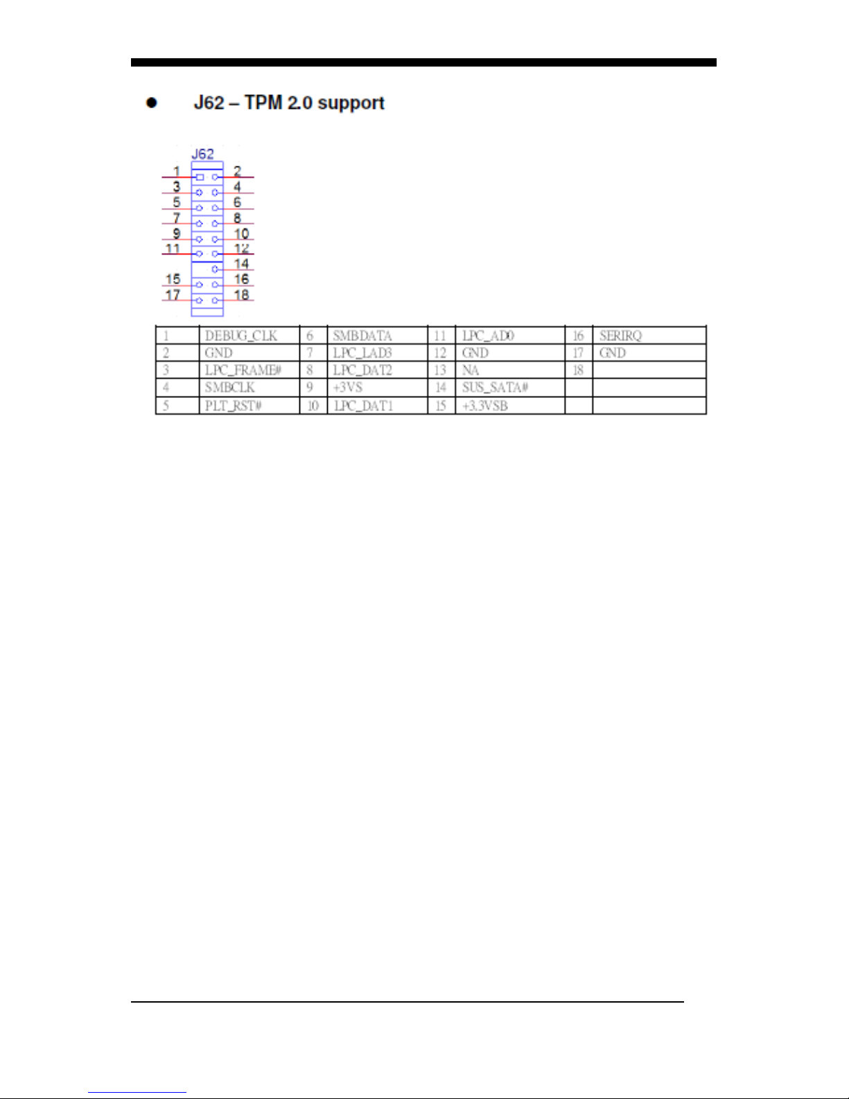
Appendix
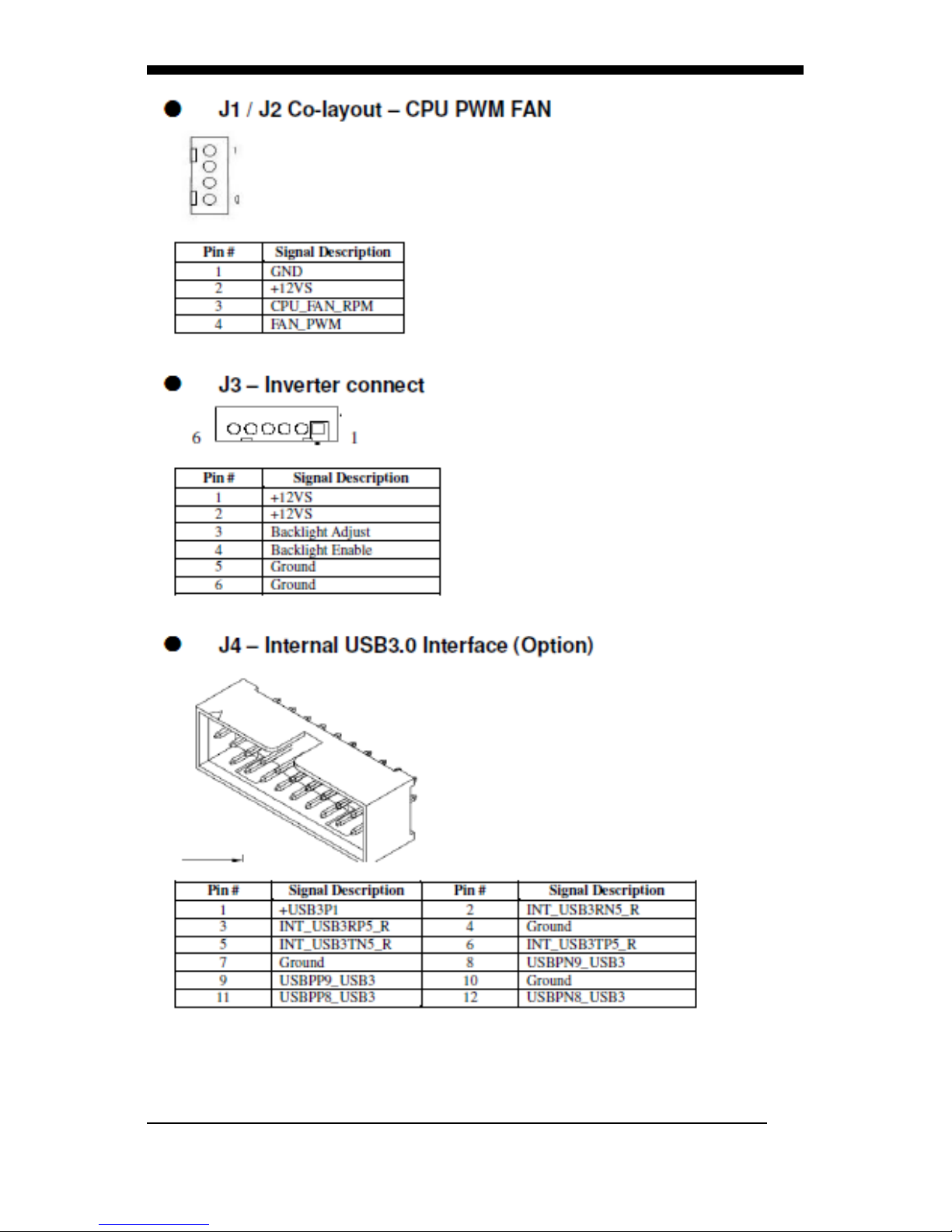
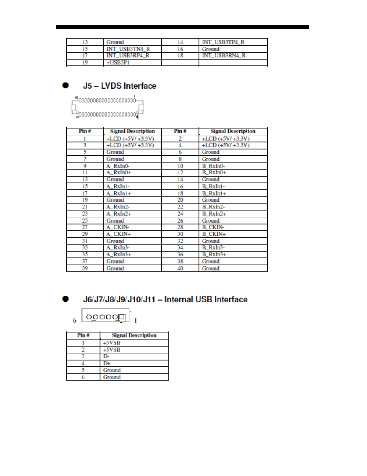
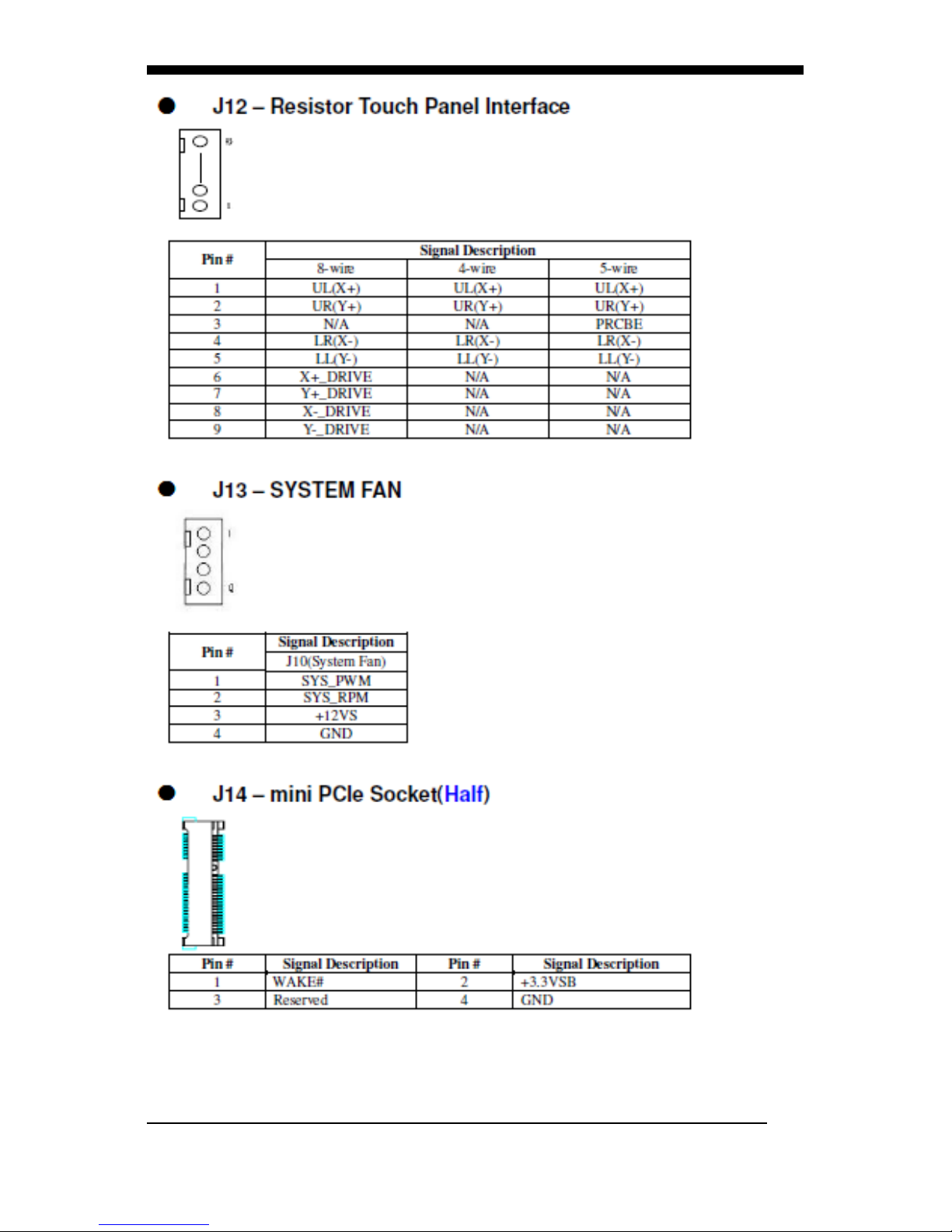
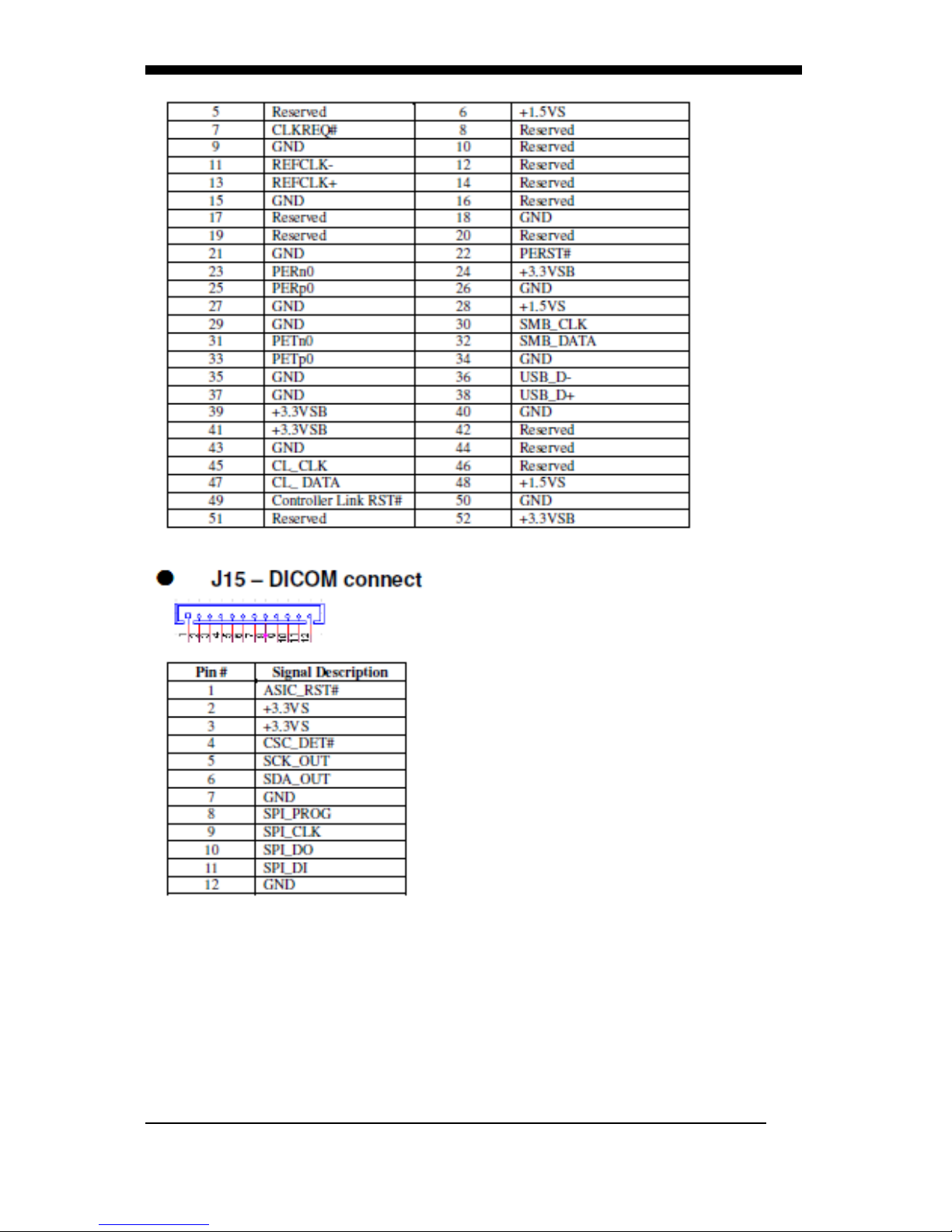
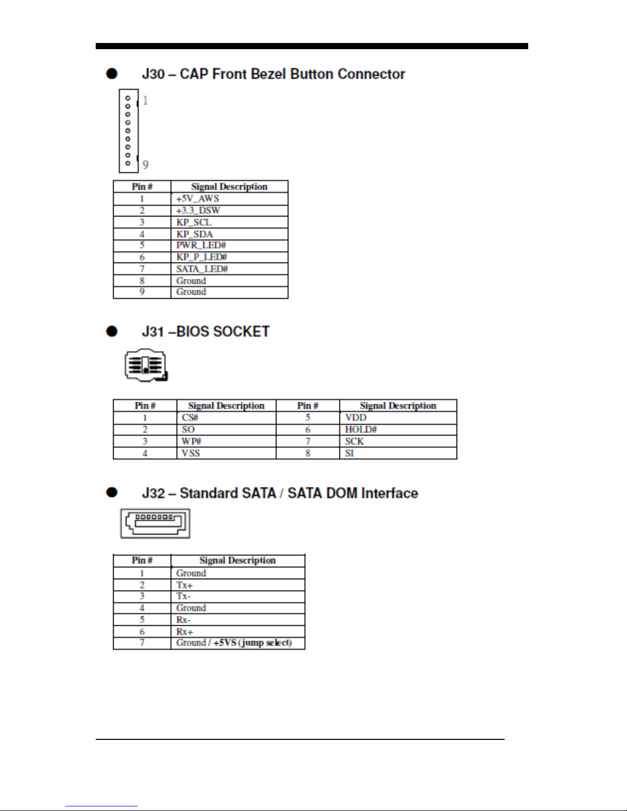
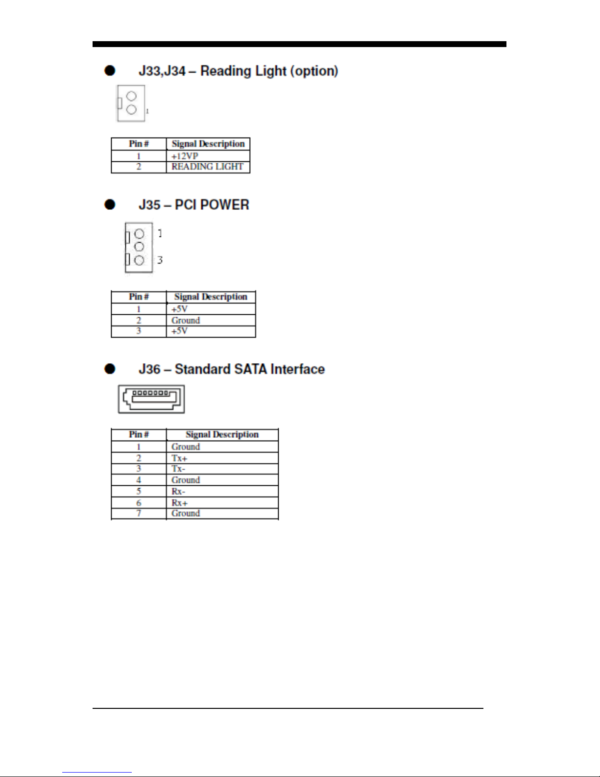
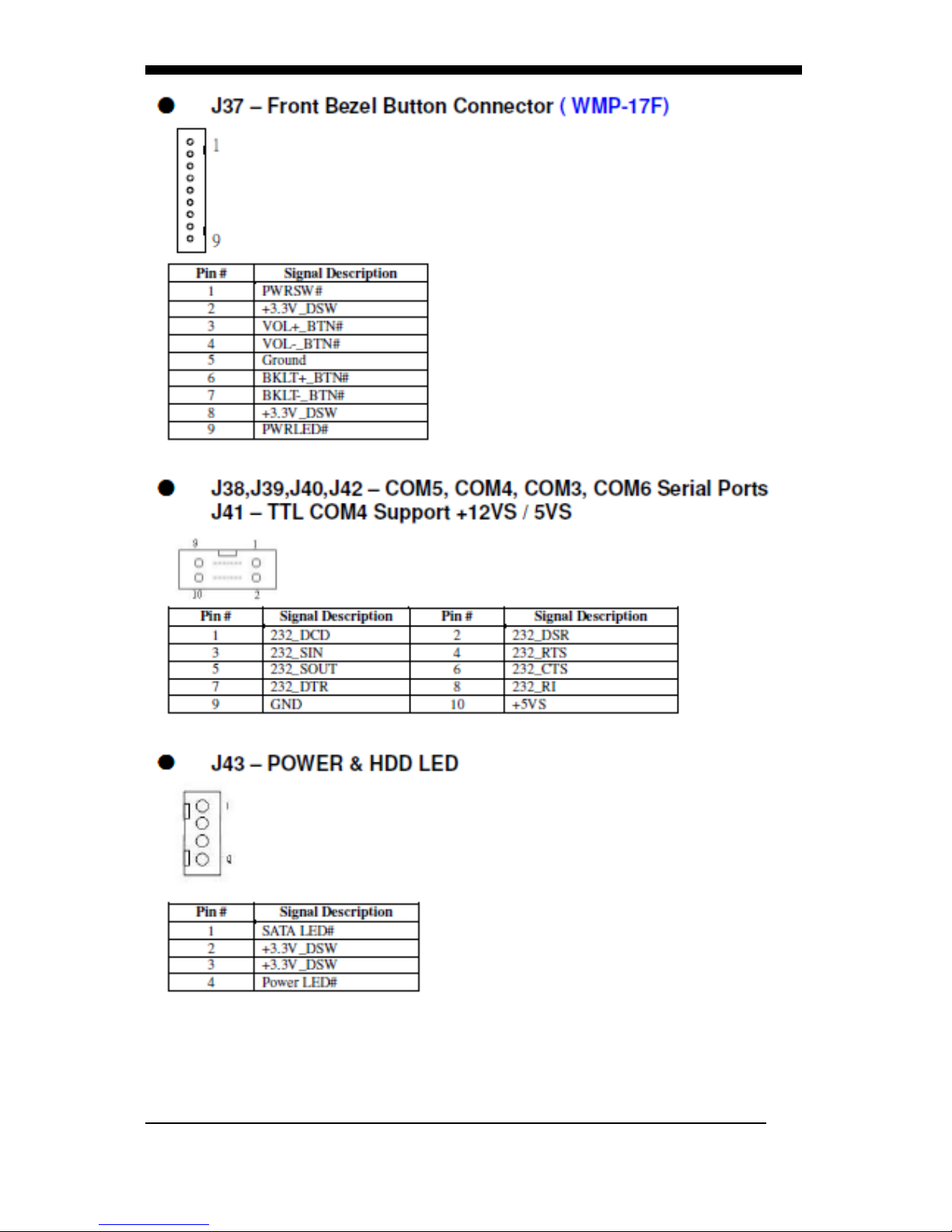
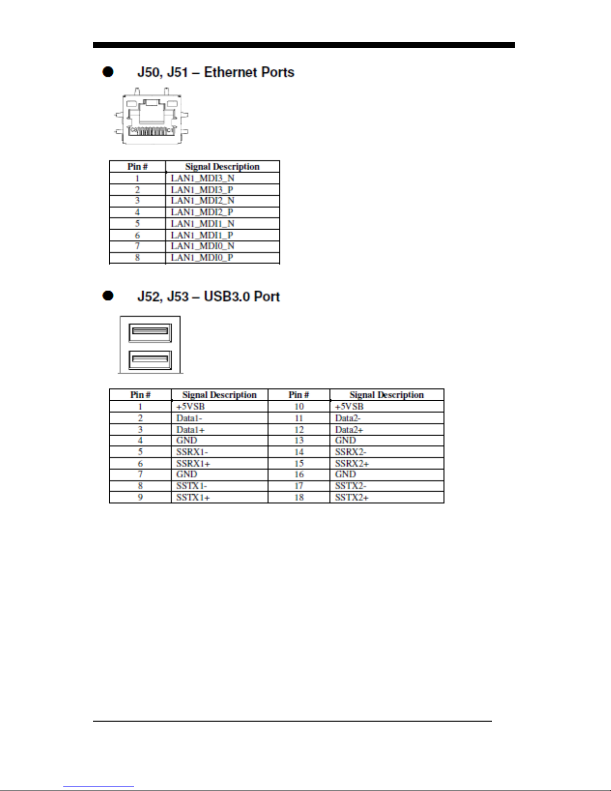
A. Jumper settings and Connectors
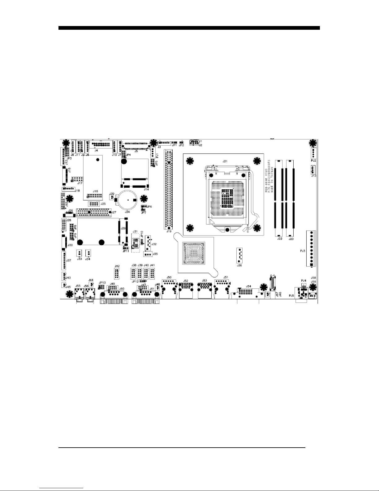
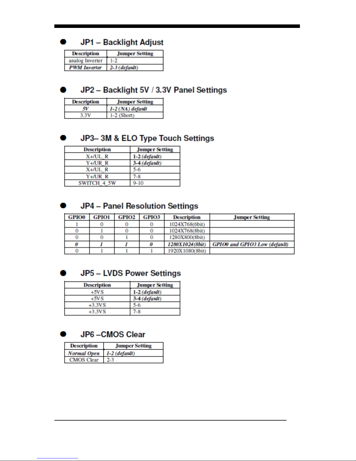
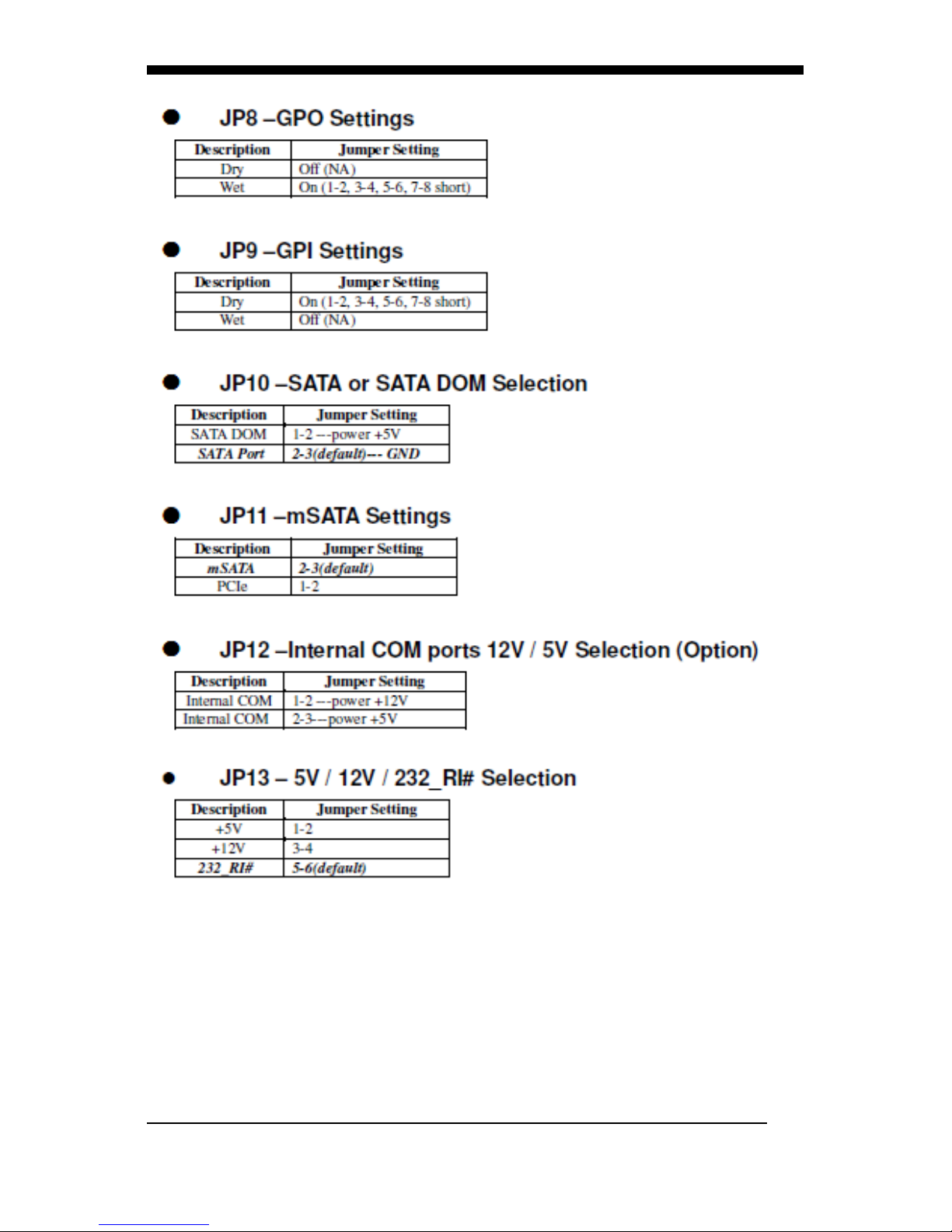
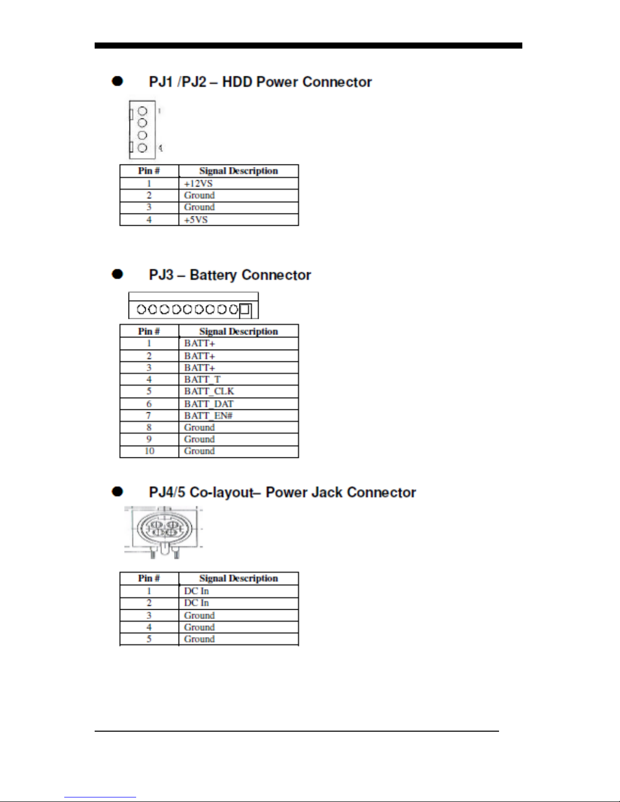
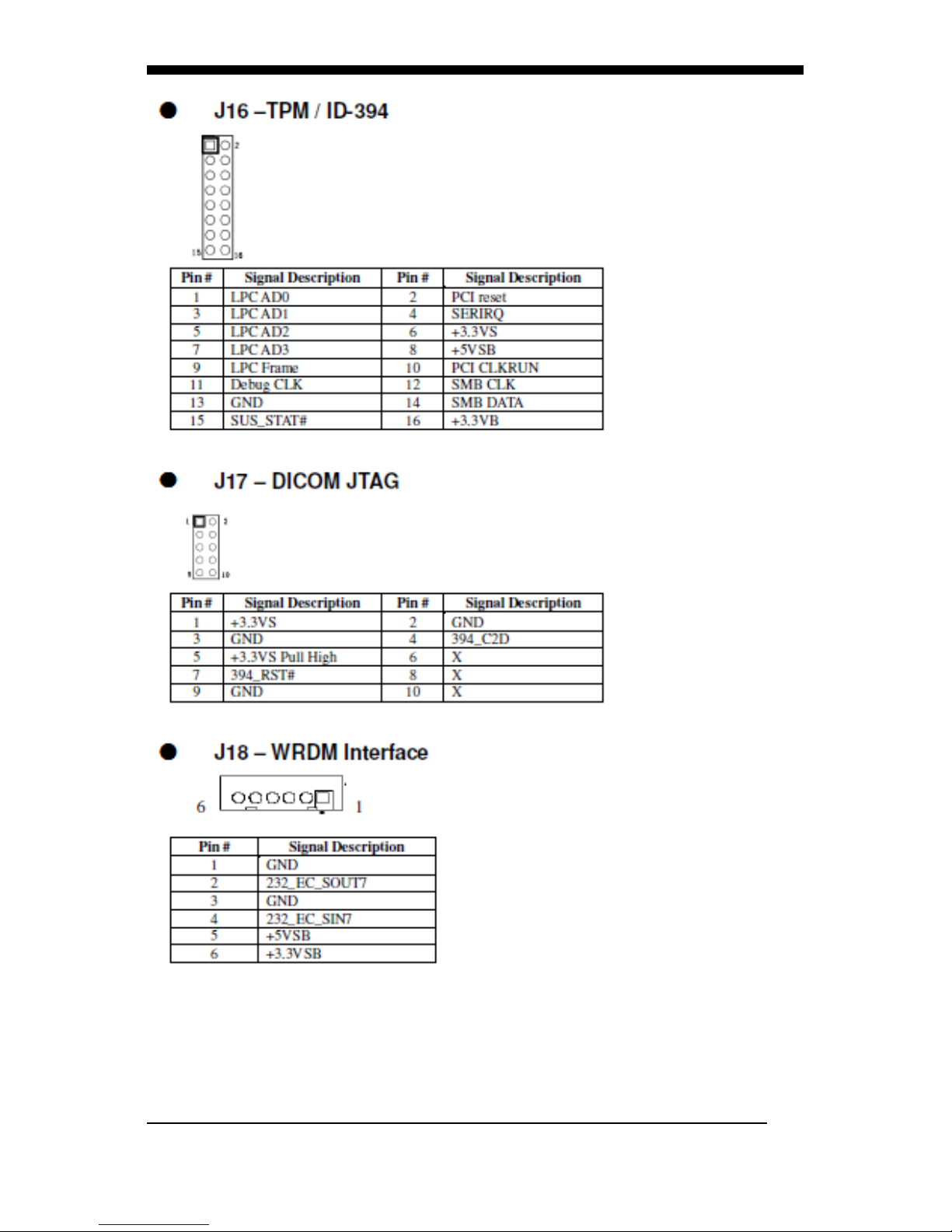
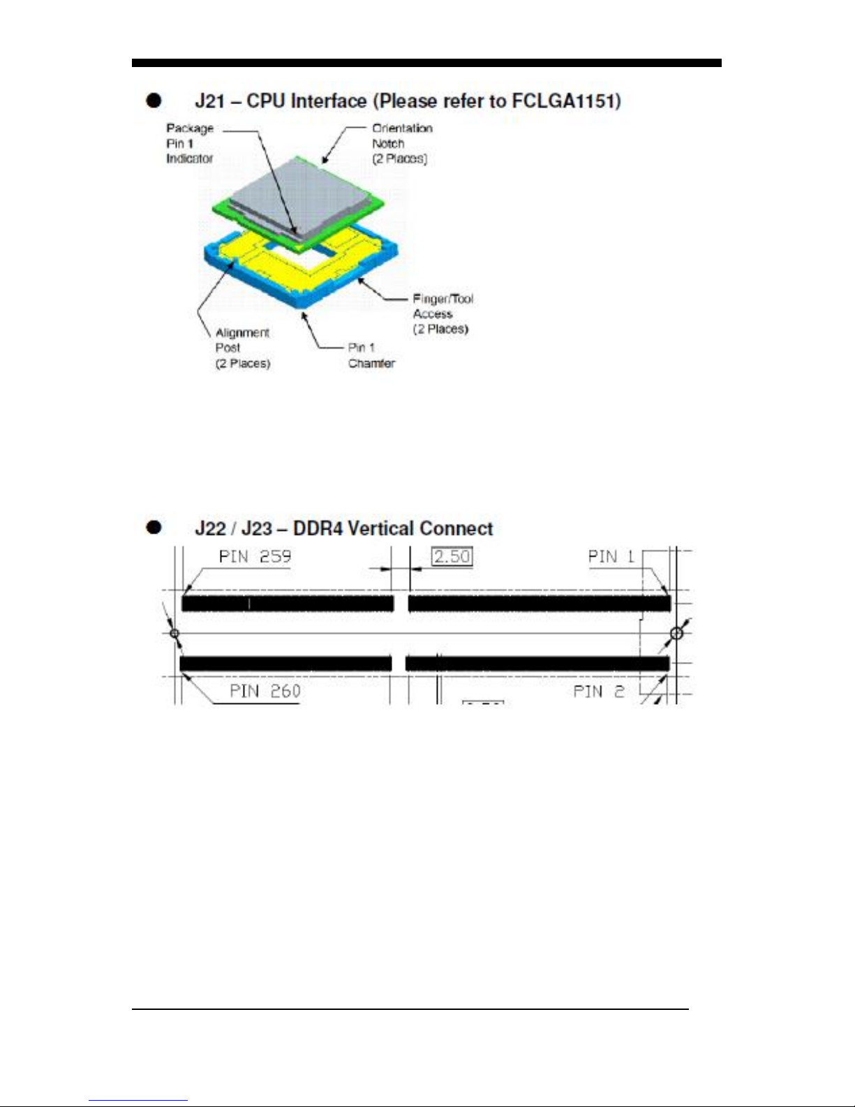
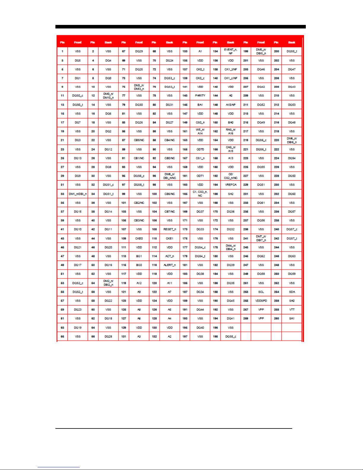
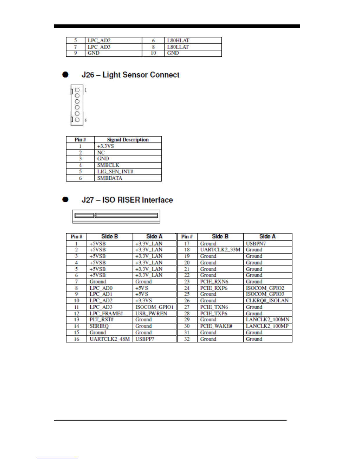
This appendix gives the definitions and shows the positions of
jumpers, headers and connectors. All of the configuration
jumpers on WMP-17F are in the proper position.
Note: Some of jumpers or connectors will be removed
base on system configuration.
Jumper and Connector Definition Block
Page 47
APPENDIX
WMP-17F User’s manual
33
Page 48
APPENDIX
WMP-17F User’s manual
34
Page 49
APPENDIX
WMP-17F User’s manual
35
Page 50
APPENDIX
WMP-17F User’s manual
36
Page 51
APPENDIX
WMP-17F User’s manual
37
Page 52
APPENDIX
WMP-17F User’s manual
38
Page 53
APPENDIX
WMP-17F User’s manual
39
Page 54
APPENDIX
WMP-17F User’s manual
40
Page 55

APPENDIX
WMP-17F User’s manual
41
Page 56
APPENDIX
WMP-17F User’s manual
42
Page 57
APPENDIX
WMP-17F User’s manual
43
Page 58

APPENDIX
WMP-17F User’s manual
44
Page 59
APPENDIX
WMP-17F User’s manual
45
Page 60

APPENDIX
WMP-17F User’s manual
46
Page 61
APPENDIX
WMP-17F User’s manual
47
Page 62
APPENDIX
WMP-17F User’s manual
48
Page 63
APPENDIX
WMP-17F User’s manual
49
Page 64

APPENDIX
WMP-17F User’s manual
50
Page 65
APPENDIX
WMP-17F User’s manual
51
Page 66
APPENDIX
WMP-17F User’s manual
52
Page 67
APPENDIX
WMP-17F User’s manual
53
Page 68
APPENDIX
WMP-17F User’s manual
54
Page 69
APPENDIX
WMP-17F User’s manual
55
B. VESA Mounting (optional kit)
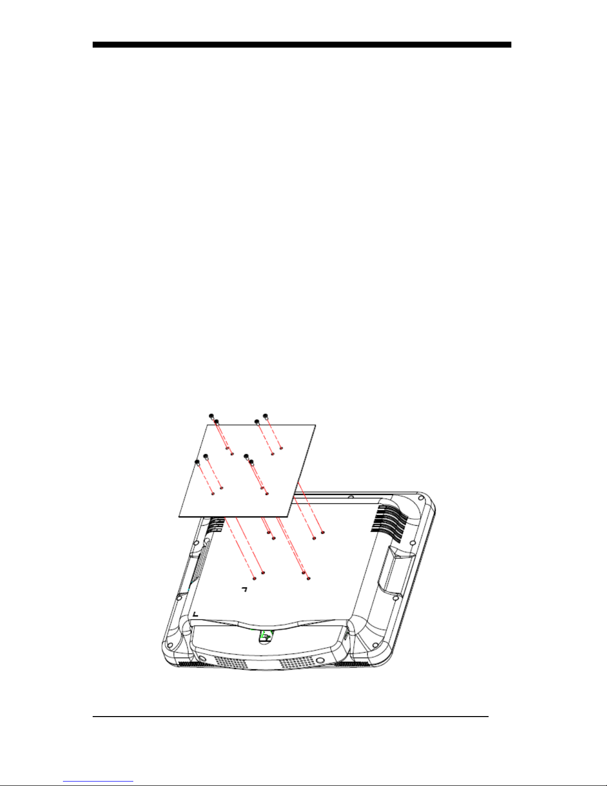
The WMP-17F also provides standard VESA mounting to help system
integrators conveniently integrate the medical panel PC into their system.
Never use any other mounting brackets except those provided by
Wincomm to prevent the unreliable fixing of WMP-17F. VESA mount
installation should be carried out by a professional technician. Please
contact the service technician or your retailer if you need this service.
Installation instructions follow:
1. The wall-mounting attachment is comprised of two parts: one back
bracket, and one mounting bracket.
2. First attach the back bracket to the rear cover of the WMP-17F, securing
it in place with four of the Phillips-head screws provided.
3. Attach the mounting bracket to the wall or another flat surface. The back
bracket slides vertically from the top into the mounting bracket. It can be
secured to the mounting bracket by screwing four of the Phillips-head
screws provided through the corresponding holes at the tops of the
mounting bracket.
Warning:
Be sure to secure the screws of the mounting bracket tightly. Injuries could
result if the WMP-17F isn’t properly secured to the mounting bracket.
Screws: M4 x 10mm
Page 70
APPENDIX
WMP-17F User’s manual
56
WMP series stand
Key Features and Benefits
Similar color as WMP series
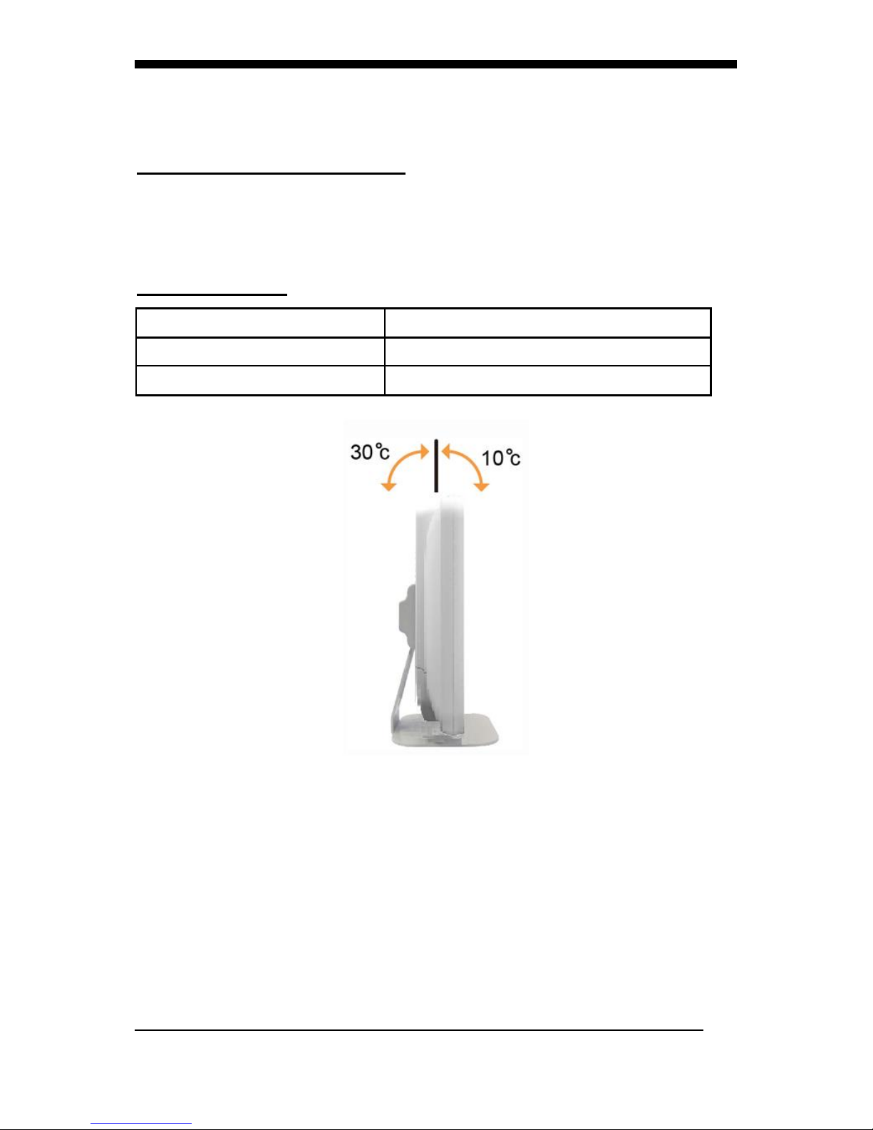
10 degree tilt down and 30 degree tilt up solution
5,000 times hinge life cycle
Specifications:
Weight Capacity:
Max 10kgs
Monitor Mounting Holes
VESA 75*75mm or 100*100mm
Application using
Desktop stand
Page 71
APPENDIX
WMP-17F User’s manual
57
C. Battery Pack Specifications (optional kit)
Battery Model133
BP-WMP226 22/3900 SA
Battery Type
Li-ion 2S2P
Minimum Capacity
3900 mAh
Nominal Voltage
7.2 V
Max. Charge Voltage
8.4V
Cut Off Voltage
6.0v
Suggested Charge
Current (Max.)
2A
System Continuous
Discharging Current
(Max.)
16.6 A
The End of Charge
Condition
150 mA/min
Discharge Protection
UVP/OCP
Charge Protection
OVP/OTP
Self-discharge Rate
10uA ~800 uA
Dimensions
133 x 47 x 21mm
Weight
240g max.
Ambient Temperature
0°C ~ +40°C
Storage Temperature
-20°C ~ +60°C
Energy
28.08Wh
Backup
53 W/ 40 min
Page 72
APPENDIX
WMP-17F User’s manual
58
D. How to disable battery when system hang up
on WMP-17F
1. When system hang up, press power button 4 seconds to turn
off system. If you can’t power on system by power button.
Please follow below step to reset system.
2. Press volume up key 10 seconds, then power LED will turn on
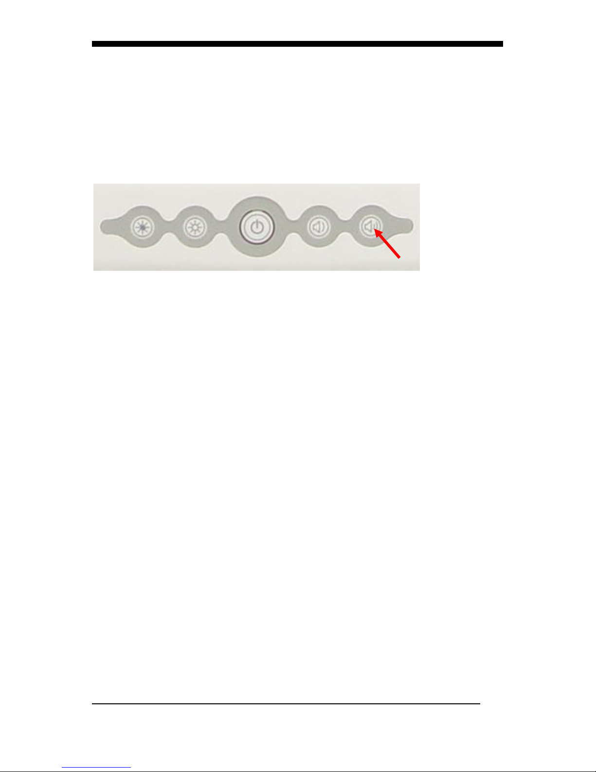
then turn off
3. Plug in AC power cord again, press power button then you can
power on system.
Page 73

APPENDIX
WMP-17F User’s manual
59
E. Scrap Computer Recycling
If the computer equipments need the maintenance or are beyond
repair, we strongly recommended that you should inform us as
soon as possible for the suitable solution. For the computers that
are no longer useful or work well, please contact with worldwide
distributors for recycling.
The worldwide distributors show on the following website:
http://www.wincomm.com.tw/contact.aspx
Note:
Follow the national requirement to dispose unit
 Loading...