

Page 1

WLP-7B20 Series
User’s Manual
P/N: 205G00WLP7B200, Version V1.3
Copyright 2016, ALL RIGHTS RESERVED.
All other brand names are registered trademarks of their
respective owner
Page 2

Copyright Notice
Copyright © 2016
All Rights Reserved.
Printed in Taiwan.
The information contained in this document is subject to change
without any notices.
Acknowledgments
Greeting & Setup
Thank you for purchasing the WLP-7B20 Panel PC. We wish that
this unit will be durable and reliable in providing your needs.
Please follow the instructions below to ensure the unit continues to
have high performance
Unpacking
After opening the carton, there will be a unit with an accessory box.
Examine the contents to see if there are damages to the unit and
if all accessories are present.
Setting up
Please read this manual carefully and remember to keep this
manual for future reference.
Safety Instructions & Cleaning
The unit has undergone various tests in order to comply with
safety standards. Inappropriate use may be dangerous. Please
remember to follow the instructions below to insure your safety
during the installation and operating process.
Transporting & Placement of unit
Page 3

III
1. When moving the unit on a cart; be very cautious. Quick stops,
excessive forces and uneven surfaces may cause the cart to
overturn thus risking the unit to fall to the ground.
2. If the Monitor display unit does fall to the ground, immediately
turn the power off and disconnect cords. Then contact a
service technician for repairs. Continual use of the unit may
result cause a fire or electric shock. Also, do not repair the
unit on your own.
3. Having two or more people transporting the display unit is
recommended. In addition, when installing the open frame by
suspending it also requires two or more people.
4. Before suspending the unit, make sure the material used for
suspension is sturdy and stable. If not properly suspended,
the display unit may fall and cause serious injury to people
standing nearby as well as to the unit itself.
5. If you wish to mount the display unit, remember to use only
the mounting hardware recommended by the manufacturer.
Electrical and Power Source Related
1. This Monitor display unit must operate on a power source as
shown on the specification label. If you are not sure what type
of power supply used in the area, consult your dealer or local
power supplier.
2. The power cords must not be damaged. Applied pressure,
added heat, and tugging may damage the power cord.
3. The power cord must be routed properly when setup takes
place. We advise that this aspect measure is to prevent
people from stepping on the cords or while the unit is
suspended to prevent flying objects from getting tangled with
Page 4

IV
the unit.
4. Do not overload the AC outlets or extension cords. Electrical
shocks or fires may occur from overloading.
5. Do not touch the power source during a thunderstorm.
6. If your hands are wet, do not touch the plug.
7. Use your thumb and index finger, grip firmly on the power cord
to disconnect from the electrical socket. By pulling the power
cord, may result in damaging it.
8. If the unit is not going to be in use for an extended period of
time, remember to disconnect the unit.
9. Connect the unit to a power source with the same numerical
value as spec. label shown. Please use only the power cord
provided by the dealer to ensure safety and EMC compliance.
Various Factors of Environment
1. Do not insert objects into the openings.
2. Do not have liquids seep into the internal areas of the Monitor
display unit.
3. Having liquids seep in or inserting objects into the unit may
result in electric shocks from taking and/or short circuiting
the internal parts.
4. Do not place the Monitor display unit in the presence of high
moisture areas.
5. Do not install the Monitor display unit in a wet environment.
6. Do not place near unit near heat generating sources.
7. Do not place the unit in a location where it will come in contact
with fumes or steam.
8. Remember to keep the Monitor display unit away from the
presence of dust.
Page 5

V
9. If water has flow in or seep in, immediately disconnect the
open frame unit. Then contact a service technician for repairs.
Ventilation Spacing
1. Do not cover or block the openings on the top and back sides of
the display unit. Inadequate ventilation may cause
overheating thus reducing the lifespan of the unit.
2. Unless proper ventilation is present, do not place unit in an
enclosed area; such as a built-in shelf. Keep a minimum
distance of 10 cm between the display unit and wall.
Cleaning the unit
1. Remember to turn off the power source and to unplug the cord
from the outlet before cleaning the unit.
2. Carefully dismount the unit or bring the unit down from
suspension to clean.
3. Use only a dry soft cloth or clean room wiper when cleaning
the LCD panel or touch screen surface. Use a soft cloth
moistened with mild detergent to clean the display housing.
4. Remember to avoid having liquids seep into the internal
components.
Servicing, Repairing, Maintenance & Safety Checks
1. If the unit is not functioning properly, observe the performance
level of the display closely to determine what type of servicing
is needed.
2. Do not attempt to repair the Monitor display unit on your own.
Disassembling the cover exposes users’ to high voltages and
other dangerous conditions. Notify and request a qualified
service technician for servicing the unit.
Page 6

VI
3. If any of the following situations occur turn the power source
off and unplug the unit. Then contact a qualified service
technician
i. A liquid was spilled on the unit or objects have fallen into
the unit.
ii. The unit is soaked with liquids.
iii. The unit is dropped or damaged.
iv. If smoke or strange odor is flowing out of the open frame
unit.
v. If the power cord or plug is damaged.
vi. When the functions of the unit are dysfunctional.
4. When part replacement is needed. Make sure service
technician uses replacement parts specified by the
manufacturer, or those with the same characteristics and
performance as the original parts. If unauthorized parts are
used it may result in starting a fire, electrical shock and/or
other dangers.
Battery Installation
Follow below instructions and notice the caution for replacing and
disposing of the RTC Lithium battery CR2032 for safety
consideration.
CAUTION:
There is danger of explosion, if battery is incorrectly replaced.
Replace only with the same or equivalent type recommended
by the manufacturer. Dispose of used batteries according to the
manufacturer’s instruction.
The specification is subject to change without notice.
Page 7
VII
Version Change History
Date
Version
Description
Remark
2015/3/13
V1.0
First release
Cosa
2015/4/20
V1.1
Modify Spec. of Touch
Cosa
2015/9/4
V1.2
Change Outline Drawing
Modify Font
Add Spec. of Shock/Vibration/Drop
Cosa
2016/3/8
V1.3
Add Panel Precautions
Add Cautions with Continuous
displaying fixed pattern
Cosa
Page 8

VIII
Table of Contents
How to Use This Manual ................................................. IX
System Overview............................................... 1
System View .................................................................. 6
I/O connectors ............................................................... 8
VESA mount installation................................................... 9
Panel mount installation ................................................ 10
Unpacking .................................................................... 12
Getting Started .................................................14
Setting up the System ................................................... 14
Installing System Software ............................................ 14
Installing the Drivers ..................................................... 15
BIOS Setup Information ...................................19
Appendix ..........................................................32
A. Jumper settings and Connectors ..................32
B. Wake UP on LAN Function ............................54
Page 9

IX
How to Use This Manual
This manual is written for the system integrator, PC technician
and knowledgeable PC end user. It describes how to configure your
WLP-7B20 Panel PC to meet various operating requirements. The
user’s manual is divided into three chapters, with each chapter
addressing a basic concept and operation of the server board.
Chapter 1: System Overview - presents what you have
inside the box and gives you an overview of the product
specifications and basic system architecture for the WLP-7B20
Panel PC.
Chapter 2: System Installation - describes how to set up
the system.
Chapter 3: BIOS Setup Information - specifies the
meaning of each setup parameter, how to get advanced BIOS
performance and update to a new BIOS. Additionally, the POST
checkpoint list will give you a guide for troubleshooting.
The contents of this manual are subject to change without prior
notice. These changes will be incorporated in new editions of this
manual.
Page 10

1
System Overview
System Specification
CPU
Intel® Celeron® J1900 2.0 GHz quad-core processor
Chipset
Intel® HD Graphics
Audio
Realtek ALC262 audio codec, 2+2 watts power
amplifier
LAN
Gigabit Ethernet x 2
Memory
Dual Channel, two DDR3 SODIMM socket support up
to 8GB DDR3L-1333
I/O
EC
Serial ATA
SATA II controller (3.0Gb/sec) Port x 2
Serial port
External RS232/RS422/RS485 x 1(Set by BIOS,
RS485 auto flow), RS232 x 1
Internal RS232 x 1
RS232 (Jumper 5V, 12V) x1
USB
External USB 2.0 type a x 3, USB3.0 x 1
Internal Mini-PCIE x2 (Default ) or USB 2.0 pin
head x 2 (Option)
Touch x 1
USB 2.0(Pin head) x 3
WDT
Generates system reset; 256 segments, 0, 1, 2…255
sec/min.
BIOS
Brand: AMI
Flash ROM size: 64Mb
Support RTC wakeup /Wake on LAN /Power on after power
failure/PnP/ACPI/RTC
Page 11
2
Display
Panel
Size
10”
12”
15”
Brand
TIANMA
TIANMA
TIANMA
Model
TM104SCH02
TM121SDS01
TM150TDS50
Resolution
(pixel)
SVGA (800 x
600)
SVGA (800 x
600)
1,024 (H) × 768
(V)
Number of Colors
262K, LVDS 6
bits
16.2M
16.7 M
View Angle (H/V)
130/110
160/140
160/160
Brightness
(cd/m2)
230
450
400
Contrast Ratio
400:1
700:1
600 :1
Interface
LVDS 6 bits
LVDS
LVDS 8-bit
Supply Voltage
(V)
3.3
3.3
3.3
Backlight
CCFL
LED
LED
life time<Hrs>
20000
50000
50000
Operating temp.
-20~70℃
-20~70℃
-30~80℃
Continuous displaying fixed pattern may induce image sticking. It’s
recommended to use screen saver or moving content periodically if
fixed pattern is displayed on the screen.
Cautions:
Continuous displaying fixed pattern may induce image sticking. It’s
recommended to use screen saver or moving content periodically if
fixed pattern is displayed on the screen.
Page 12
3
Touch Screen: resistive or capacitive types
ELO
HIGGSTEC
Type
5 wire Full Flat Res. touch
Projective Capacitive
Glove
Any type glove
No
Input Mode
Point: Finger or touch pen
Drag: Finger
Finger
P-Cap touch pen
Vandal
NA
NA
Interface
USB
USB
Light
Transmission
80± 5%
90± 3%
Hardness
4H
7H
Glass thickness
2.5 mm
3.45 mm
Linearity
X≦ 1%, Y≦ 1%
X≦ 1.0%, Y≦ 1.0%
Resolution
4096x4096
25ppi
Lifetime
36 million activations
100 million activations
Touch Controller
EETI EXC7700 microcontroller with USB interface and specific for 4, 5,
8 wire touch screen.
Storage
HDD
2.5” SATA HDD drive bay x 1 (with
anti-vibration mechanism)
SATA DOM
2nd SATA connector pin7 with VCC_(+5V)
Expansion
Mini-PCIe
52 pin card-edge type compatible to PCI
Express*Base specification 2.0 x 2
External I/O
USB
USB 2.0 x 3, USB 3.0 x 1
(internal USB 2.0 x 5 one for Res. Touch or PCT,
two for Mini PCI-e or USB 2.0, Three for Free )
COM
RS232/RS422/RS485 x 1(Set by BIOS, RS485 auto
flow), RS232 x 2
LAN
RJ-45 x 2 (Gigabit Ethernet)
Audio
3.5mm phone jack connector * 2 ( Line-out, and
Mic-in)
Page 13
4
DVI output
DVI-I x 1
Power
Power
DC-In connector x 1 (Jack with locker)
Switch
Reset key
LED indicator on
Aluminum bezel
Green: power On/Off
Red: HDD status
Power Input
DC12V~28V
Power Adapter
AC 90 ~ 264V / 47 ~ 63 Hz / DC output 12V
Mechanical & Environmental
Material construction
Front bezel is Aluminum or SECC, others
are SECC enclosure
Aluminum bezel Color
Black / Silver
Front Panel Protection
Res. Touch IP66 / P-CAP touch IP69K
ID design
Panel mount (default)
Operation Temperature
12V DC Input 0~50℃
(IEC60068-2-56, air flow cooling)
12V DC Input 0~40℃
(IEC60068-2-2, natural cooling)
32V DC Input 0~40℃
(IEC60068-2-2, natural cooling)
Storage Temperature
-20~65℃
Operation Relative
Humidity
10%~90%, non-condensing
Storage Relative
Humidity
10%~90%, non-condensing
Mounting
Panel mount/VESA (75x75)
Net Weight (Kg)
Gross Weight (Kg)
10”
3.5 Kg
5.5
12”
4.5
6.5
15”
5.5
8.5
Page 14
5
Shock/Vibration/Drop
Shock
Vibration
Drop
General
Operating:
Pulse shape
:
Half-sine waveform
Impact
acceleration:15g
Pulse duration:11
ms
Number of shocks
:
18 shocks (3 shock
for each ±axis)
Orientation
:±
X, ±Y
and ±Z axes
Operating:
5 ~ 500Hz ,
Acceleration:1.0G
Sweep time:15
minutes
Number of cycle:1
cycle for each axis
Vibration axes:X, Y
and Z
3 Feet height free
drop still survive,
(test surface:
concrete, with
packing)
6 surfaces
Page 15
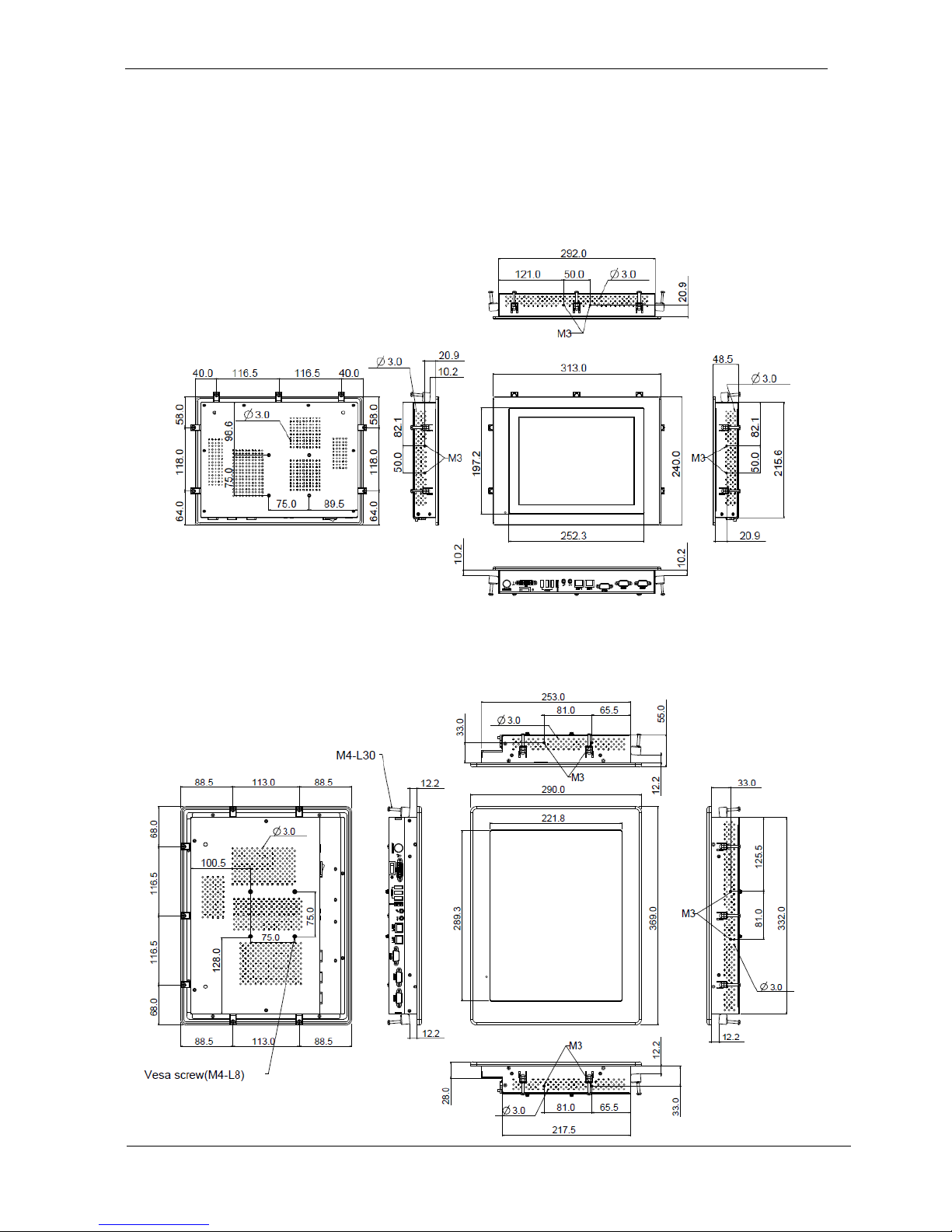
6
System View
WLP-7B20-10 Outline Drawing (Panel Mount)
WLP-7B20-12 Outline Drawing (Panel Mount)
Page 16
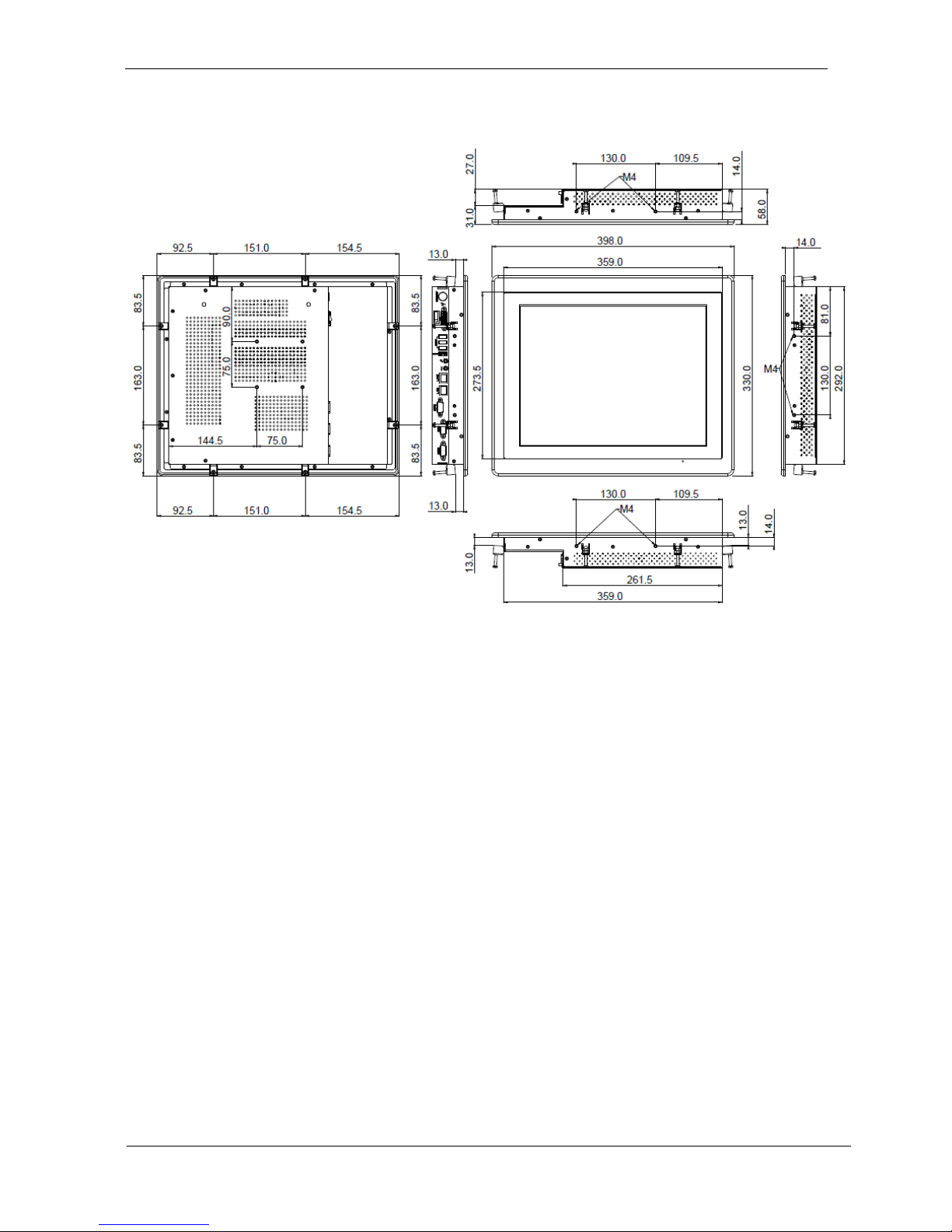
7
WLP-7B20-15 Outline Drawing (Panel Mount)
Page 17
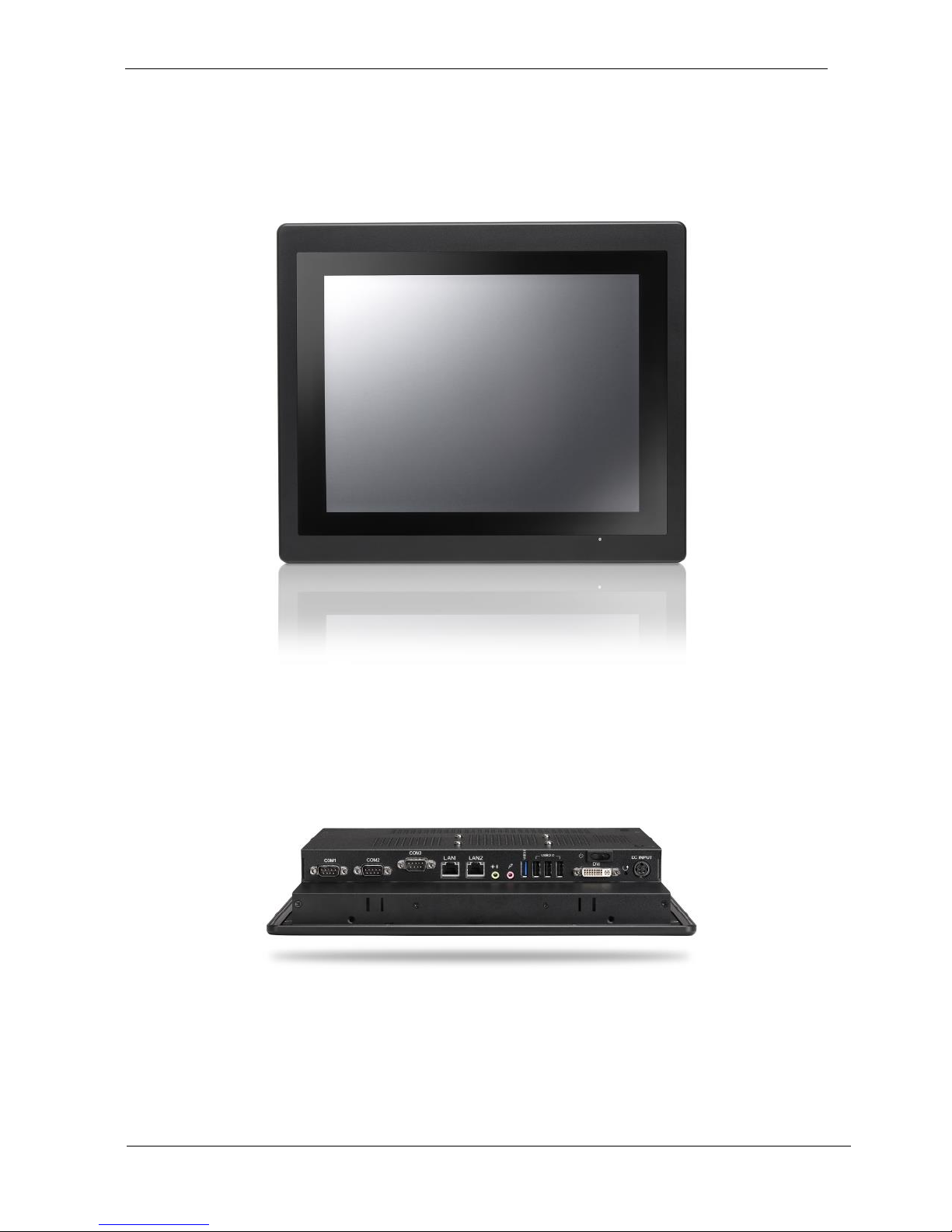
8
I/O connectors
Note: Share the same place with DVI output, DVI and VGA not
simultaneously
Page 18
9
VESA mount installation
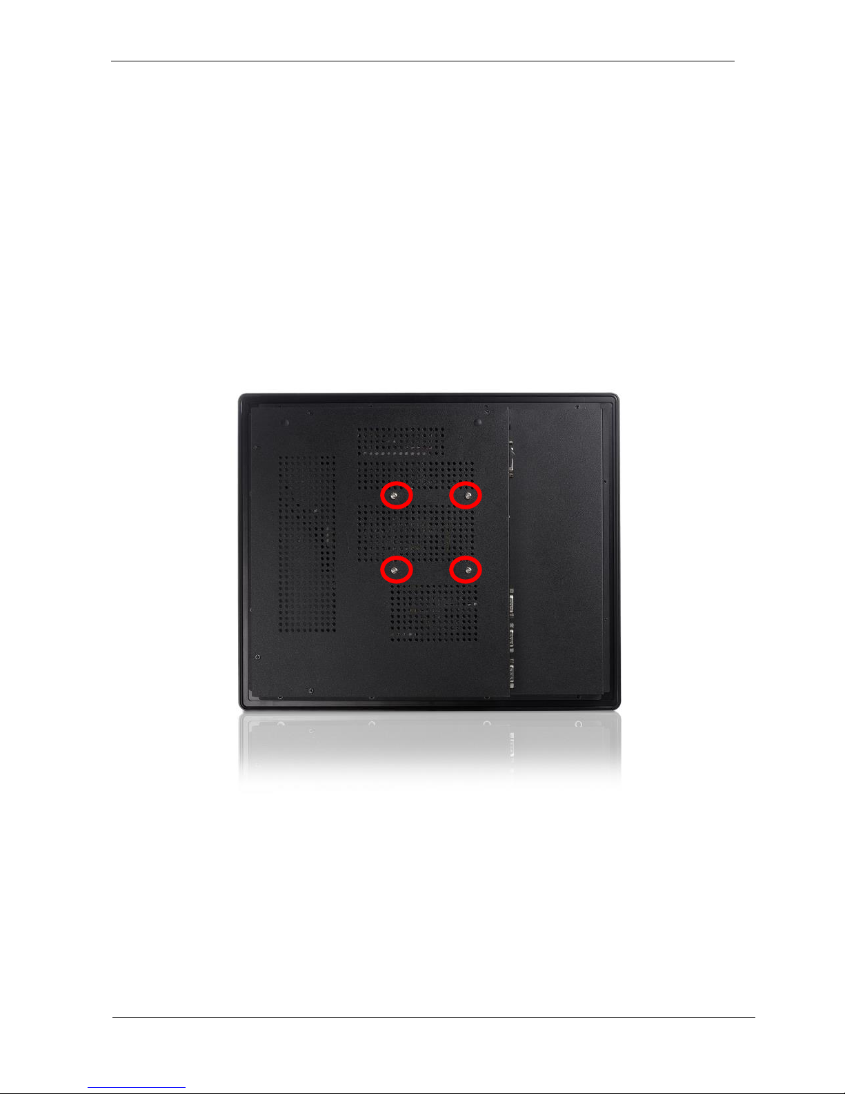
Please use the supplied 4 x M4-L10 screws for VESA mounting. And
as below VESA mounting holder is just a diagrammatic drawing. You
can choose any standard VESA 75x75 mm mounting holder to mount
our machine.
For use only with UL listed Wall Mount Bracket with minimum
weight/load bearing capacity 10 Kg
Page 19
10
Panel mount installation
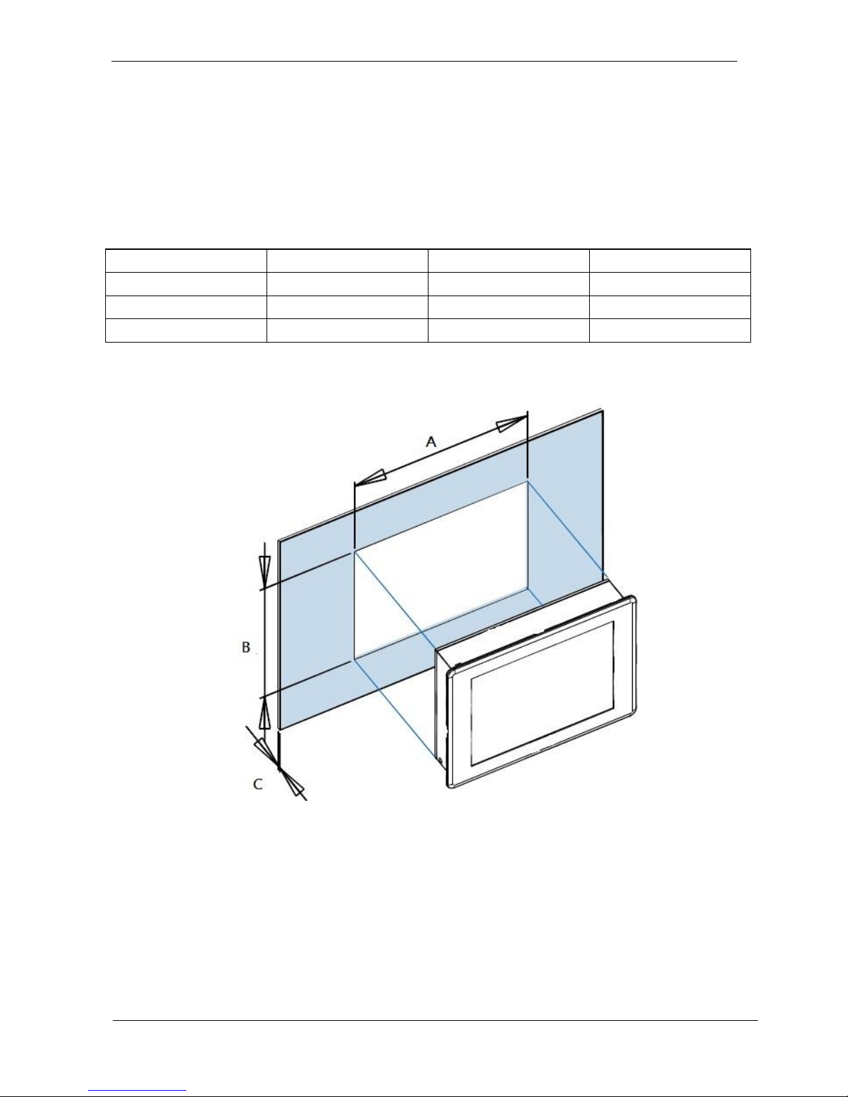
1. The Panel PC can be panel mounted and comes with brackets and
screws for this purpose. The required cutout for panel mounting and
maximum panel thickness is shown below.
A B
C
WLP-7B20-10
296
224
12
WLP-7B20-12
345
266
15
WLP-7B20-15
365
298
16
Unit: mm
Page 20
11
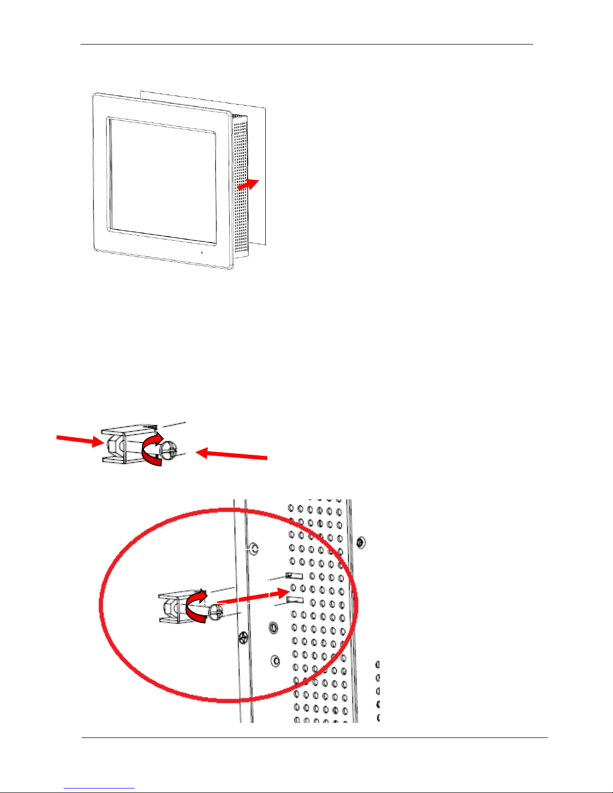
STEP 1
Panel Mount
Put Panel PC on the fixture (Wall, Panel…..) from the front, with the
sides of the front bezel shown on the outside.
STEP2
1
2
3
Page 21

12
Use provided mounting kits to fix the Panel PC and the customer’s
fixture
Unpacking
After unpacking the shipping carton, you should find these
standard items:
The WLP-7B20 Panel PC series
Accessory box including the followings:
– AC-DC adapter x 1
– AC power cord x 1
– Screws (M3x0.5PxL6) x 8
Page 22

13
– Screws (M4x0.7PxL44) x 8
– CD-ROM for drivers, utility, user manual(in PDF format)
Inspect all the items. If any item is damaged or missing, notify
your dealer immediately.
Page 23
14
Getting Started
This chapter tells you how to set up the system.
Setting up the System
The following is a summary of the steps in setting up the
system for use.
CAUTION: Make sure that power to the system and
each of the devices to be connected is switched OFF
before plugging in the connectors.
1. Make any required external connections such as the
keyboard, and mouse.
2. Plug the appropriate end of the power cord into the power
connector of the system. Then plug the other end of the power
cord to an electrical outlet.
3. Press the power switch of the system to turn on the system’s
power.
4. If necessary, run the BIOS SETUP program to configure the
system (see Chapter 3).
5. Install the software drivers if necessary.
Installing System Software
Recent releases of operating systems from major vendors include
setup programs, which load automatically and guide you through
hard disk preparation and operating system installation. The
guidelines below will help you determine the steps necessary to
install your operating system on the Panel PC hard drive.
NOTE: Some distributors and system integrators may have
already pre-installed system software prior to shipment of
Page 24

15
your Panel PC.
Installing software requires an installed HDD. Software can be
loaded in the WLP-7B20 Panel PC using any of below methods:
Method 1: Use the Ethernet
You can use the Ethernet port to download software from the
net to the HDD that has been pre-installed in WLP-7B20 Panel
PC
Method 2: Use the COM Port
By connecting another PC to the WLP-7B20 Panel PC with an
appropriate cable, you can use transmission software to
transmit Operation System Software to the HDD that has been
pre-installed in the WLP-7B20 Panel PC.
Method 3: Use a External CD-ROM
In order to boot up system from USB-CD/DVD drive, please
connect USB-CD/DVD drive, turn on computer power, keep on
pressing “F11” key, go into BIOS quick boot menu, select
“USB-CD ROM”, WAIT FOR 20 SECONDS, then press enter,
system OS will boot up from USB-CD/DVD drive directly
Then you can use the external CD-ROM to transmit the software
to the HDD that has been pre-installed in the WLP-7B20 Panel
PC
Installing the Drivers
After installing your system software, you will be able to set up the
LAN, VGA, Audio and USB functions. All drivers are stored in a CD
disc, which can be found in your accessory pack.
Page 25

16
The various drivers and utilities in the disc have their own text files
that help users install the drivers and understand their functions.
Follow the sequence below to install the drivers:
Step 1 – Install Intel® INF Driver
Step 2 – Install Intel® VGA Driver
Step 3 – Install Intel® LAN Driver
Step 4 – Install Audio Driver
Step 5 – Install Touch Driver
Step 1 – Install Intel® INF Driver
1. Open fie of chipset
2. Click on the setup.exe
3. Follow the instructions that the window shows
4. The system will help you install the driver automatically
5. Reboot system
Step 2 –Install Intel® VGA Driver
1. Open fie of VGA
2. Select the OS folder your system is
3. Click on the .exe file located in the OS folder
4. Follow the instructions that the window shows
5. The system will help you install the driver automatically
6. Reboot system
Step 3 – Install Intel® LAN Driver
1. Open fie of LAN
2. Click on the setup.exe
3. Follow the instructions that the window shows
4. The system will help you install the driver automatically
5. Reboot system
Page 26

17
Step 4 – Install Audio Driver
1. Open fie of LAN
2. Click on the setup.exe
3. Follow the instructions that the window shows
4. The system will help you install the driver automatically
5. Reboot system
Step 5 – Install Touch Driver
1. Open fie of touch
2. Click on the setup.exe
3. Follow the instructions that the window shows
4. The system will help you install the driver automatically
5. Reboot system
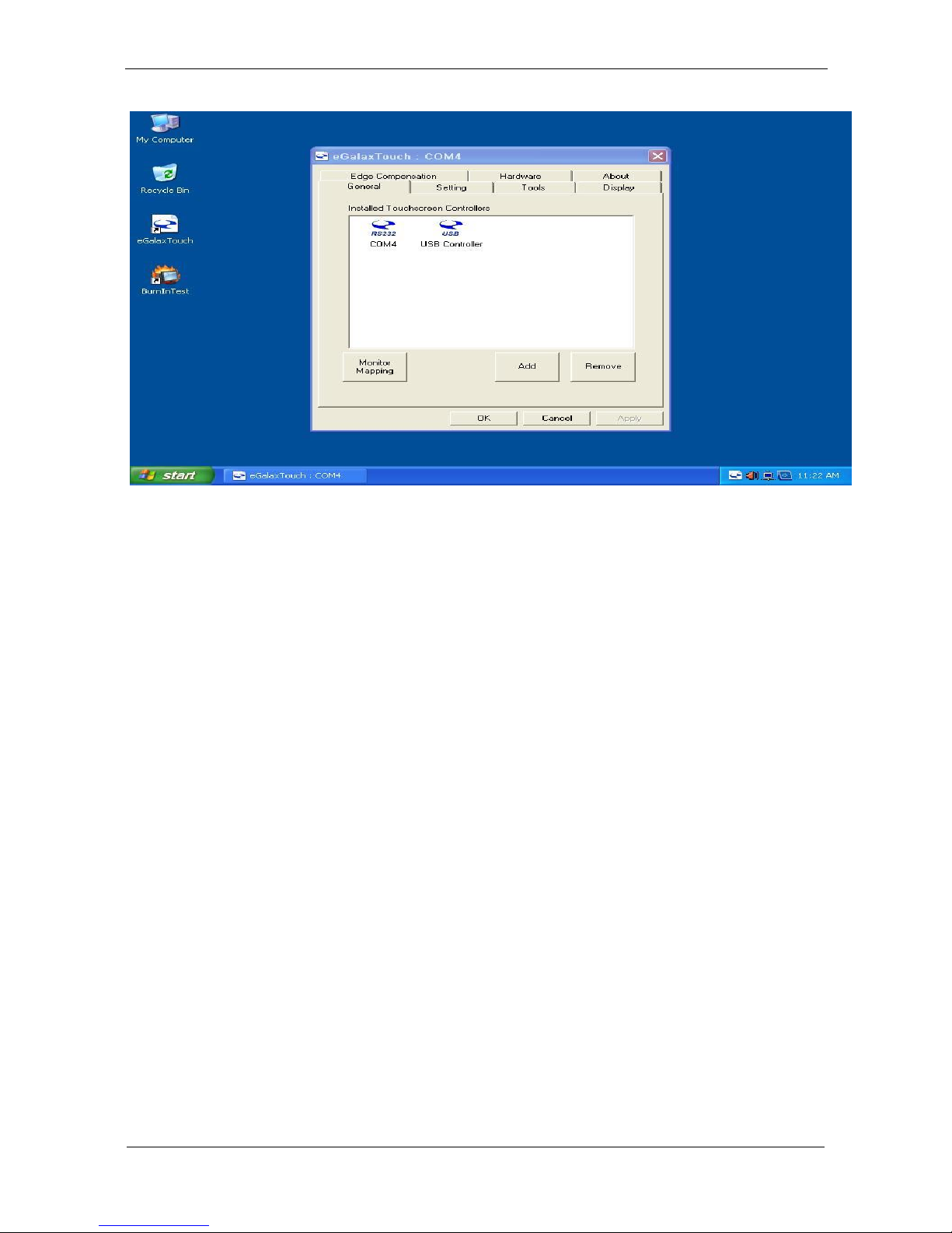
Note:
eGalax Touch driver supports both resistive and capacitive touch
screens, user can find 2 touch icons shown in utility, please set up
touch screen by selecting the correlative one.
(USB controller: resistive touch screen, USB controller: capacitive
touch screen)
Page 27
18
Page 28

19
BIOS Setup Information
BIOS Introduction
The AMI BIOS (Basic Input / Output System) installed in your
computer system’s ROM supports Intel processors. The BIOS
provides critical low-level support for a standard device such as disk
drives, serial ports and parallel ports. It also adds virus and
password protection as well as special support for detailed
fine-tuning of the chipset controlling the entire system.
BIOS Setup
The AMI BIOS provides a Setup utility program for specifying the
system configurations and settings. The BIOS ROM of the system
stores the Setup utility. When you turn on the computer, the AMI
BIOS is immediately activated. Pressing the <Del> key
immediately allows you to enter the Setup utility. If you are a little
bit late pressing the <Del> key, POST (Power On Self Test) will
continue with its test routines, thus preventing you from invoking
the Setup. If you still wish to enter Setup, restart the system by
pressing the ”Reset” button or simultaneously pressing the <Ctrl>,
<Alt> and <Delete> keys. You can also restart by turning the
system Off and back On again. The following message will appear
on the screen:
Press <DEL> to Enter Setup
In general, you press the arrow keys to highlight items, <Enter>
to select, the <PgUp> and <PgDn> keys to change entries, <F1>
for help and <Esc> to quit.
When you enter the Setup utility, the Main Menu screen will appear
on the screen. The Main Menu allows you to select from various
Page 29

20
setup functions and exit choices.
Main
This section provides information on the BIOS information, Memory
information, and Battery information
System Date
Set the system date. Use the <Tab> key to switch between data
elements.
System Time
Set the system time. Use the <Tab> key to switch between time
elements.
Page 30

21
Advanced
Launch OpROM Support
Launch PXE OpROM
Enables or disables Boot Option for Legacy Network Devices.
Launch Storage OpROM
Enables or disables Boot Option for Legacy Mass Storage Devices
with Option ROM.
PCI Subsystem Settings
PCI ROM Priority
In Case of multiple Option ROMs (Legacy and EFI Compatible),
specifies what PCI Option ROM to launch.
PCI Latency Timer
Value to be programmed into PCI Latency Timer Register.
VGA Palette Snoop
Page 31

22
Enables or disables VGA Palette Registers Snooping.
PERR# Generation
Enables or Disables PCI Device to Generate PERR#.
SERR# Generation
Enables or Disables PCI Device to Generate SERR#.
Relaxed Ordering
Enables or Disables PCI Express Device Relaxed Ordering.
Extended Tag
If ENABLED allows Device to use 8-bit Tag field as a requester.
No Snoop
Enables or Disables PCI Express Device No Snoop option.
Maximum Payload
Set Maximum Payload of PCI Express Device or allow System
BIOS to select the value
Maximum Read Request
Set Maximum Read Request Size of PCI Express Device or
allow System BIOS to select the value.
ASPM Support
Set the ASPM Level: Force L0 – Force all links to L0 State :
AUTO – BIOS auto configure : DISABLE – Disables ASPM.
Extended Synch
If ENABLED allows generation of Extended Synchronization
patterns.
ACPI Settings
Enables ACPI Auto Conf
Enables or Disables BIOS ACPI Auto Configuration.
Enable Hibernation
Enables or Disables System ability to Hibernate (OS/S4 Sleep
Page 32

23
State). This option may be not effective with some OS.
ACPI Sleep State
Select the highest ACPI sleep state the system will enter, when
the SUSPEND button is pressed.
S5 RTC Wake Settings
Wake System with Fixed Time
Enables or disables system wake on alarm event. When
enabled, the system will wake on the time specified.
Wake system with Dynamic Time
Enables or disables system wake on alarm event. When
enabled, the system will wake on the current time+Increase
minute(s).
CPU Configuration
Hyper-Threading
Enabled for Windows XP and Linux (OS optimized for
Hyper-Threading Technology) and Disabled for other OS (OS
optimized for Hyper-Threading Technology)
Core-Multi Processing
Enable or Disable Core-Multi Processing mode.
Execute Disable Bit
XD can prevent certain classes of malicious buffer overflow
attacks when combined with a supporting OS (Windows Server
2003 SP1, Windows XP SP2, SuSE Linux 9.2, RedHat
Enterprise 3 Update 3.)
Limit CPUID Maximum
Disabled for Windows XP.
IDE Configuration
ATA or IDE Configuration
Page 33

24
Select ATA or IDE configuration.
Configure SATA AS
Select a configuration for SATA controller.
HDD Acoustic Power Ma
Option to enable or disable HDD Acoustic Power Management.
DiPM
Option to enable or disable DiPM
Intel IGD SWSCI OpRegion
DVMT Mode Select
Selects DVMT Mode used by Internal Graphics Device.
DVMT/FIXED Memory
Selects DVMT/FIXED Mode Memory size used by Internal
Graphics Device.
IGD – Boot Type
Select the Video Device which will be activated during POST.
This has no effect if external graphics present.
LCD Panel Type
Select LCD panel used by Internal Graphics Device by
selecting the appropriate setup item.
Panel Scaling
Select the LCD panel scaling option used by the Internal
Graphics Device.
GMCH BLC Control
Back Light Control Setting
BIA Control
Spread Spectrum clock
>>Hardware: Spread is controlled by chip;
>>Software: Spread is controlled by BIOS.
Page 34

25
TV1 Standard
TV2 Standard
Active LFP
Select the Active LFP Configuration.
No LVDS:VBIOS does not enable LVDS.
INT-LVDS:VBIOS enables LVDS driver by Integrated encoder.
SDV0 LVDS:VBIOS enables LVDS driver by SDV0.
USB Configuration
Legacy USB Support
Allows USB devices to be used in MS-DOS.
EHCI Hand-off
This is a workaround for 0Ses without EHCI hand-off support.
The EHCI ownership change should be claimed by EHCI driver.
USB transfer time-out
The time-out value for Control, Bulk, and Interrupt transfers.
Device reset time-out
USB mass storage device Start Unit command time-out.
Device power-up delay
Maximum time the device will take before it properly reports
itself to the HOST Controller.
‘Auto’ uses default value: for a Root port it is 100 ms, for a Hub
port the delay is taken from Hub descriptor.
F71869 Super IO Configuration
Serial Port 0 Configuration
Set Parameters of Serial Port 0 (COM A).
Serial Port 1 Configuration
Set Parameters of Serial Port 1 (COM B).
F71869 H/W Monitor
Page 35

26
Monitor hardware status
Second Super IO Configuration
Serial Port 1 Configuration
Set Parameters of Serial Port 1 (COM C).
Serial Port 2 Configuration
Set Parameters of Serial Port 2 (COM D).
Serial Port 3 Configuration
Set Parameters of Serial Port 3 (COM E).
Serial Port 4 Configuration
Set Parameters of Serial Port 4 (COM F).
Serial Port Console Redirection
Serial Port Console Redirection.
Chipset
Host Bridge/South Bridge
This screen provides information on Host Bridge/South Bridge
Page 36

27
parameters.
Page 37
28
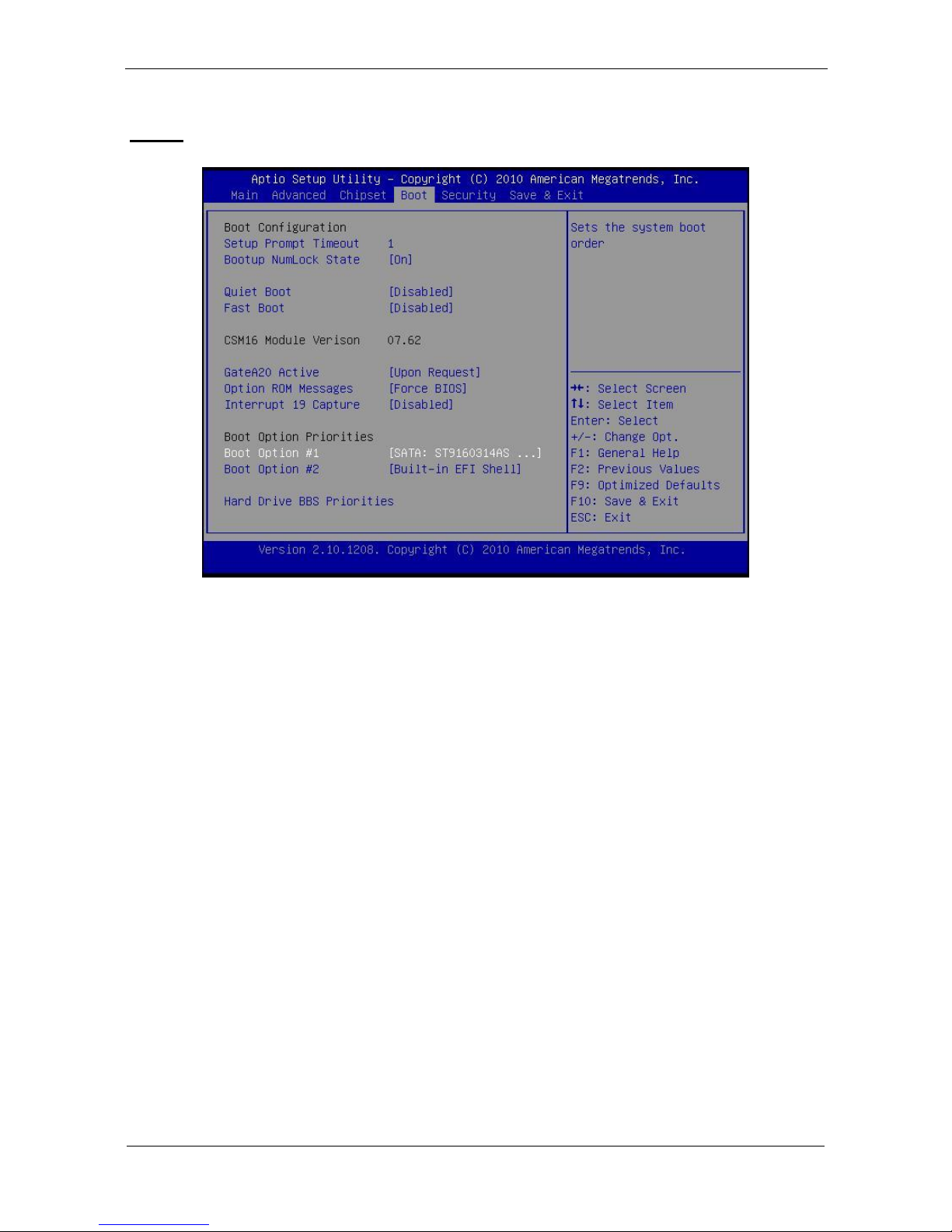
Boot
Setup Prompt Timeout
Number of seconds to wait for setup activation key.
65535(0xFFFF) means indefinite waiting.
Bootup Numlock State
Selects the keyboard NumLock state.
Quiet Boot
Allows you to determine whether to display the AMI Logo at
system startup. Disabled displays normal POST message.
Fast Boot
Enables or disables the quick boot function to speed up the
system boot-up process to shorten the waiting time for entering
the operating system and to deliver greater efficiency for daily
use.
GateA20 Active
Page 38

29
This option is useful when any RT code is executed above 1MB.
Upon Request GA20 can be disabled using BIOS services.
(Default)
Always Do not allow disabling GA20.
Option ROM Messages
Sets display made for option ROM.
Interrupt 19 Capture
Enables or disables Option ROMs to Trap Int 19.
Boot Option Priorities
Specifies the sequence of loading the operating system from the
installed hard drives.
Security
Enables or disables the security chip. It is recommended that you
use this function with the Administrator/User password.
Page 39
30
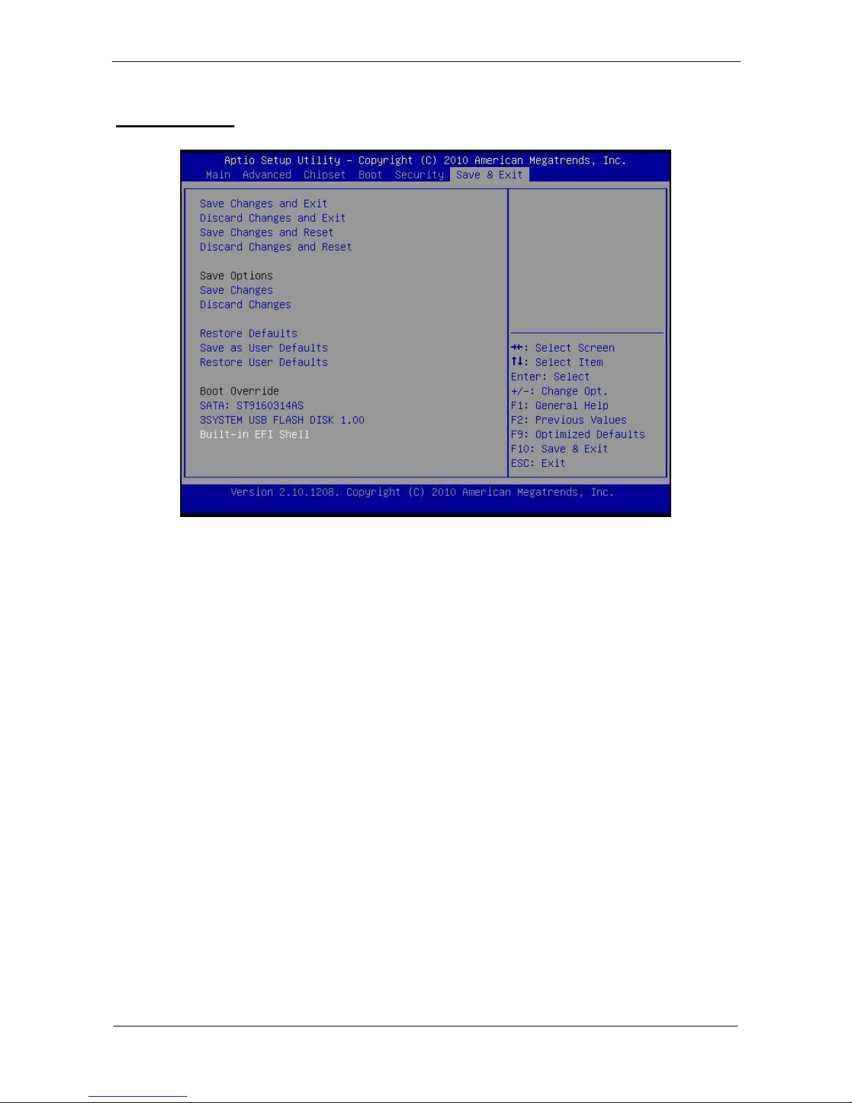
Save & Exit
Save Changes and Exit
Exit system setup after saving the changes.
Discard Changes and Exit
Exit system setup without saving any changes.
Save Changes and Reset
Reset the system after saving the changes.
Discard Changes and Reset
Reset system setup without saving the changes.
Save Changes
Save the changes done so far to any of setup options.
Discard Changes
Discard the changes done so far to any of setup options.
Restore Defaults
Restore/load default values for all the setup options.
Page 40

31
Save as User Defaults
Save the changes done so far as User Defaults.
Restore User Defaults
Restore the User Defaults to all the setup options.
EFIGUI_FLASH
Press <Enter> to execute the simple EFI GUI Flash Program.
Page 41
32
Appendix
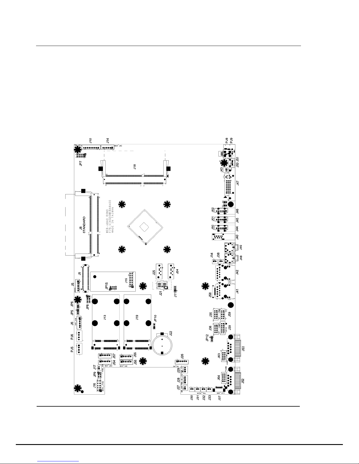
A. Jumper settings and Connectors
This appendix gives the definitions and shows the positions
of jumpers, headers and connectors. All of the configuration
jumpers on WLP-7B20 series are in the proper position.
Note: Some of jumpers or connectors will be removed
base on system configuration.
Jumper and Connector Definition Block
Page 42
33
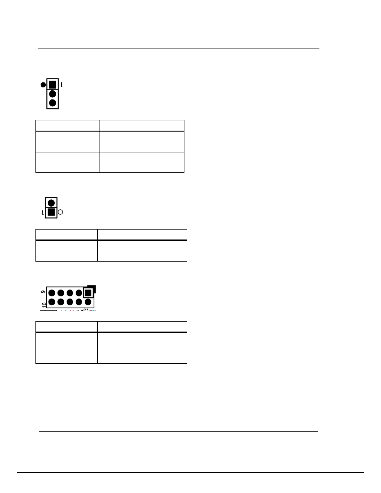
JP5 – Backlight Type Selection
Description
Jumper Setting
Analog
Inverter
1-2 (for 10”)
PWM
Inverter
2-3(for 12’’/15”)
JP6 – Backlight control level Selection
Description
Jumper Setting
+3.3V
1-2
+5V
OPEN (default)
JP7 – Touch Panel Type Selection
Description
Jumper Setting
3M type
1-2, 3-4
(default)
ELO type
5-6,7-8
Page 43

Page 44

35
JP11 – SATA / SATADOM Selection
Description
Jumper Setting
SATA
2-3(default)
SATA DOM
1-2
JP12 – COM3 Power Selection
Description
Jumper Setting
+5VS
2-3(default)
+12VS
1-2
JP13,J14 –Y cable* Support both DVI+VGA
Description
JP13
JP14
No support
(default)
Open
Open
Support
1-2
1-2
*Support Wincomm Y cable only.
Page 45
36
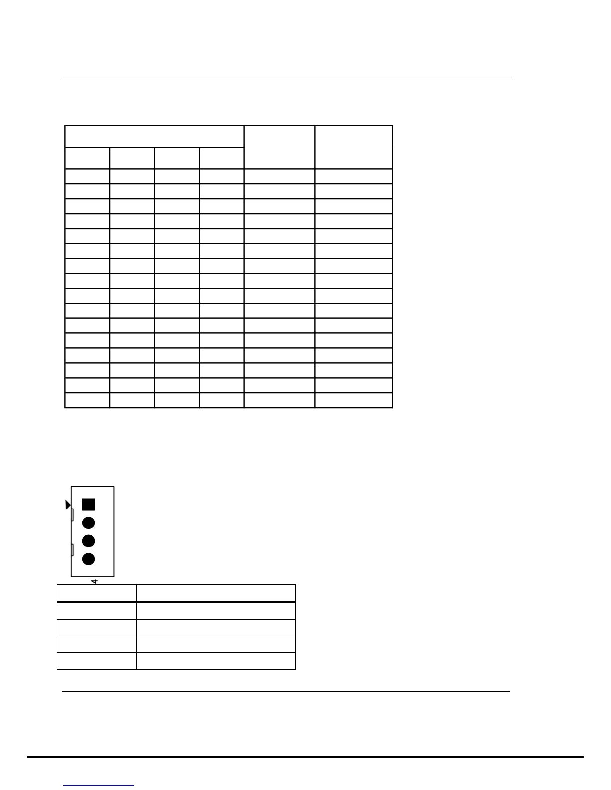
JP15 –Panel Resolution Selection
1-2 3-4 5-6 7-8
0 0 0 0 800x600 6bit
0 0 0 1 1024x768 6bit
0 0 1 0 1024x768 8bit
0 0 1 1 1280x768 6bit
0 1 0 0 1280x800 6bit
0 1 0 1 1280x960 6bit
0 1 1 0 1280x1024 8bit
0 1 1 1 1366x768 6bit
1 0 0 0 1366x768 8bit
1 0 0 1 1440x900 8bit
1 0 1 0 1440x1050 8bit
1 0 1 1 1600x900 8bit
1 1 0 0 1680x1050 8bit
1 1 0 1 1600x1200 8bit
1 1 1 0 1920x1080 8bit
1 1 1 1 1920x1200 8bit
JP15 jumper setting
Panel
Resolution
Color Depth
Connector Definition
PJ5 /PJ6 – HDD Power Connector
Pin #
Signal Description
1
+12VS
2
GND
3
GND
4
+5VS
Page 46
37
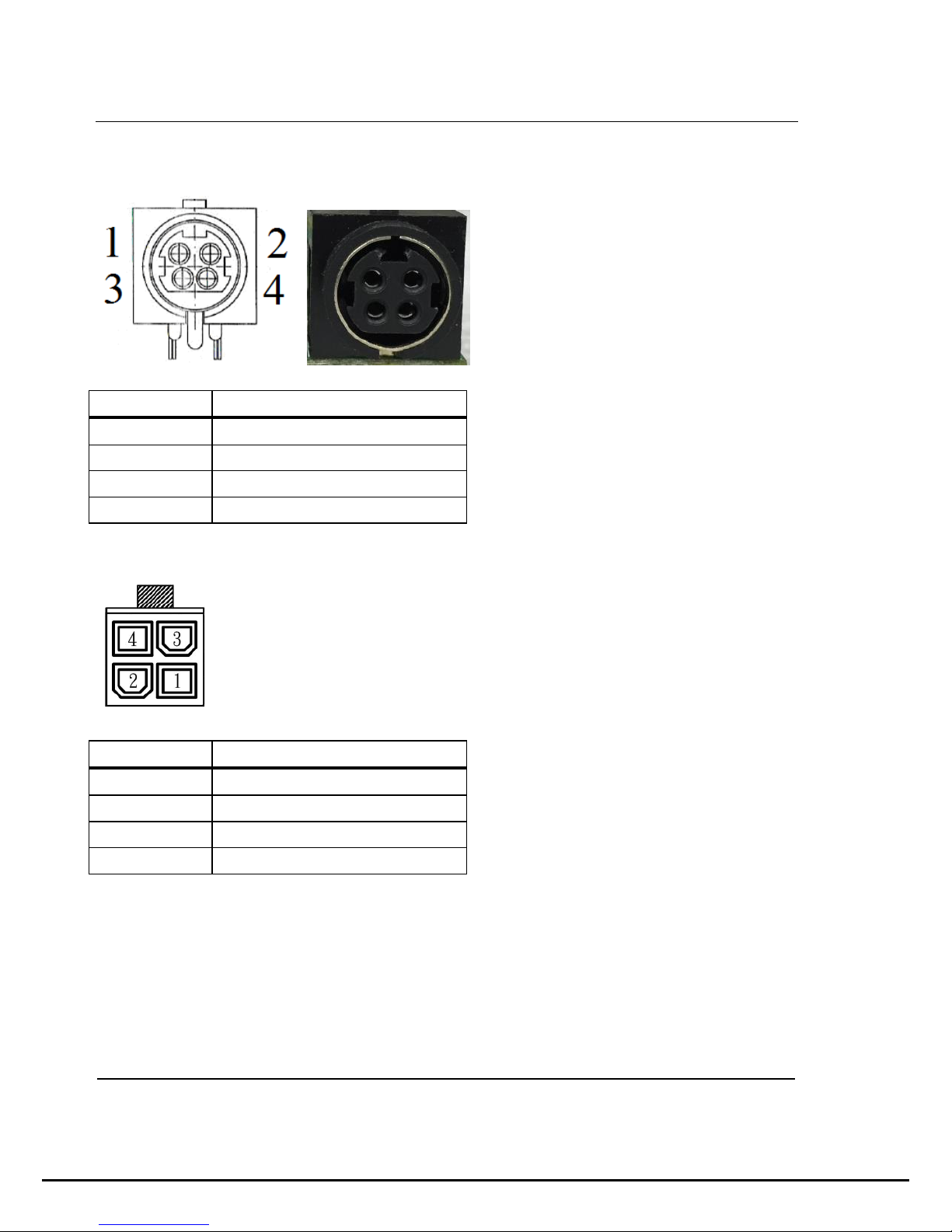
PJ8 – Power Jack
Pin #
Signal Description
1
DC In
2
DC In
3
GND
4
GND
PJ9 – Power Input Connector
Pin #
Signal Description
1
GND
2
GND
3
DC In
4
DC In
Page 47

38
J5 – LCD Inverter Wafer Header
Pin #
Signal Description
1
+12VS
2
+12VS
3
Backlight Control
4
Backlight Enable
5
GND
6
GND
J6, J54, J56 – Internal USB 2.0 Pin Header
Pin #
Signal Description
1
+5VSB
2
+5VSB
3
Data -
4
Data +
5
GND
6
GND
Page 48
39
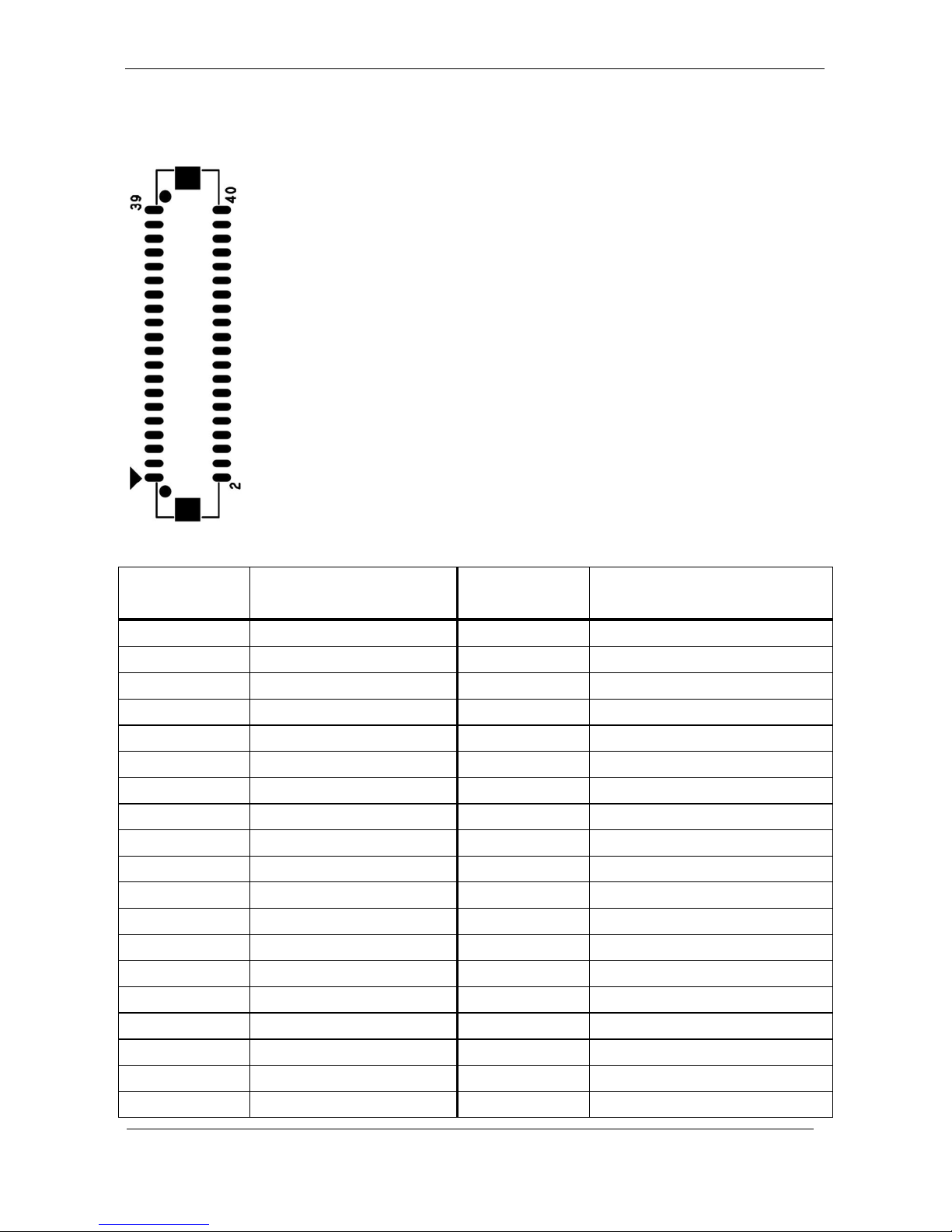
J9 – LVDS Interface
Pin #
Signal
Description
Pin #
Signal Description
39
GND
40
GND
37
Ground
38
GND
35
A_TXD3+
36
B_TXD3+
33
A_TXD3-
34
B_TXD3-
31
GND
32
GND
29
A_CLK+
30
B_CLK+
27
A_CLK-
28
B_CLK-
25
GND
26
GND
23
A_TXD2+
24
B_TXD2+
21
A_TXD2-
22
B_TXD2-
19
GND
20
GND
17
A_TXD1+
18
B_TXD1+
15
A_TXD1-
16
B_TXD1-
13
GND
14
GND
11
A_TXD0+
12
B_TXD0+
9
A_TXD0-
10
B_TXD0-
7
GND
8
GND
5
GND
6
GND
3
+LVDS PWR
4
+LVDS PWR
Page 49

40
1
+LVDS PWR
2
+LVDS PWR
J10 – Resistance Touch Screen Interface
Pin #
Signal Description
8-wire
4-wire
5-wire
1
UL(X+)
UL(X+)
UL(X+)
2
UR(Y+)
UR(Y+)
UR(Y+)
3
N/A
N/A
PROBE
4
LR(X-)
LR(X-)
LR(X-)
5
LL(Y-)
LL(Y-)
LL(Y-)
6
X+_DRIVE
N/A
N/A
7
Y+_DRIVE
N/A
N/A
8
X-_DRIVE
N/A
N/A
9
Y-_DRIVE
N/A
N/A
J13 / J19 – Mini PCI Express Socket
J14 –P-CAP Touch screen interface*
Pin #
Signal Description
Page 50

41
1
+5VSB
2
+5VSB
3
Data -
4
Data +
5
Ground
6
Ground
* Res(J10) with P-CAP(J14) select one
J15 –TPM / ID-394
Pin # Signal
Description
Pin #
Signal
Description
16
+3.3VSB
15
SUS_STAT#
14
SMB DATA
13
GND
12
SMB CLK
11
Debug CLK
10
CLKRUN#
9
LPC Frame#
8
+5VSB
7
LPC AD3
6
+3.3VS
5
LPC AD2
4
SERIRQ
3
LPC AD1
2
PLT reset#
1
LPC AD0
J16 – For JTAG
Page 51
42
Pin # Signal
Description
Pin #
Signal
Description
10
Reserved
9
GND
8
Reserved
7
+3.3V
6
Reserved
5
+3.3V
4
C2D
3
GND
2
GND
1
+3.3V
J17 – Panel Temp Sensor Connector
Pin #
Signal
Description
1
PANEL_SENSOR
2
GND
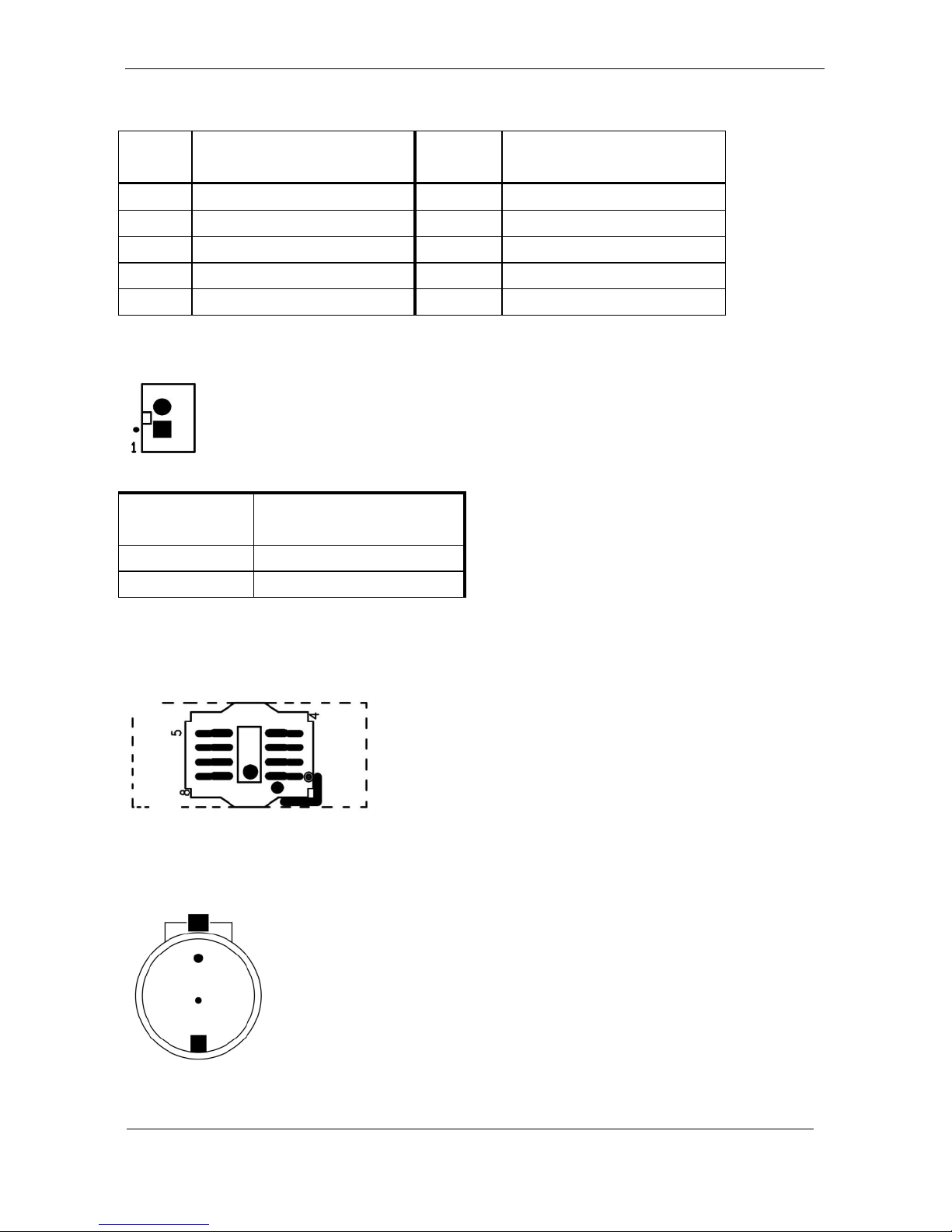
J21 – BIOS Socket
J22 – Battery Socket
Page 52
43
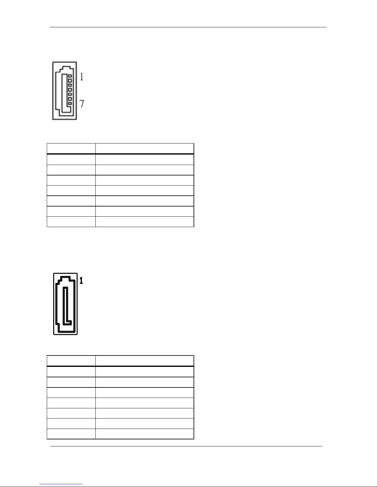
J24 – Standard SATA / SATA DOM Interface
Pin #
Signal Description
1
Ground
2
Tx+
3
Tx-
4
Ground
5
Rx-
6
Rx+
7
Ground / +5VS
J25 – Standard SATA Interface
Pin #
Signal Description
1
Ground
2
Tx+
3
Tx-
4
Ground
5
Rx-
6
Rx+
7
Ground
Page 53

44
J26 – PS2 KB/MS
Pin #
Signal Description
1
KBDATA
2
MSDATA
3
Ground
4
+5VSB
5
KBCLK
6
MSCLK
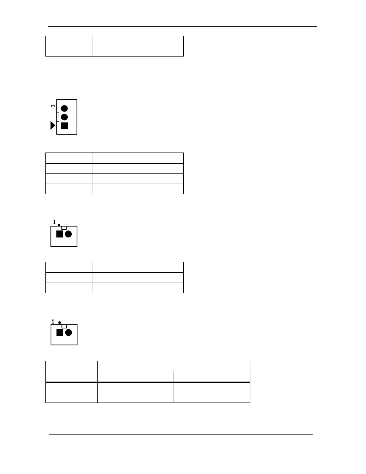
J27 – MB Heater Connector
Pin #
Signal Description
2
GND
1
+12VSB
J28 – Power / HDD LED
Pin #
Signal Description
4
PWR_LED#
3
+3.3VSB
Page 54
45
2
+3.3VSB
1
SATA_LED#
J29 – Heater Error / Heating LEDs
Pin #
Signal Description
3
+3.3V
2
HEATER_LED#
1
ERROR_LED#
J30, J31, J32, J33 – Panel Heater Connector
Pin #
Signal Description
1
+12VSB
2
GND
J34, J38 – RIGHT / LEFT CH for Speaker.
Pin #
Signal Description
J34 (RIGHT CH)
J38 (LEFT CH)
1
ROUT+
LOUT+
2
ROUT-
LOUT-
Page 55

46
J35 – Internal COM4 Serial Port
Pin #
Signal
Description
Pin #
Signal Description
2
232_DSR#
1
232_DCD#
4
232_RTS#
3
232_SIN
6
232_CTS#
5
232_SOUT
8
232_RI#
7
232_DTR#
10
+5VS
9
GND
J36 – Internal COM3 Serial Port
Pin #
Signal
Description
Pin #
Signal Description
2
232_DSR#
1
232_DCD#
4
232_RTS#
3
232_SIN
6
232_CTS#
5
232_SOUT
8
232_RI#
7
232_DTR#
10
+5VS/+12VS
9
GND
Page 56

47
J37 – Light Sensor Connect
Pin #
Signal Description
1
+3.3V
2
NC
3
Ground
4
SCL1
5
NC
6
SDA1
J39 – GPIO Connect
Pin #
Signal
Description
Pin #
Signal Description
2
GEN_GPI1
1
GEN_GPO1
4
GEN_GPI2
3
GEN_GPO2
6
GEN_GPI3
5
GEN_GPO3
8
GEN_GPI4
7
GEN_GPO4
10
+5V
9
+5V
12
GND
11
GND
Page 57
48
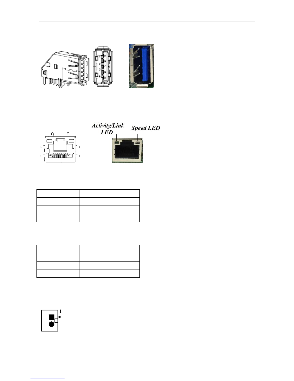
J40 – External USB 3.0 Port
J41 / J42 –External RJ45 Ethernet Port
Activity/Link LED
Status
Description
OFF
No Link
Blinking
Data Activity
ON
Link
Speed LED
Status
Description
OFF
10 Mbps
Green
100 Mbps
Orange
1 Gbps
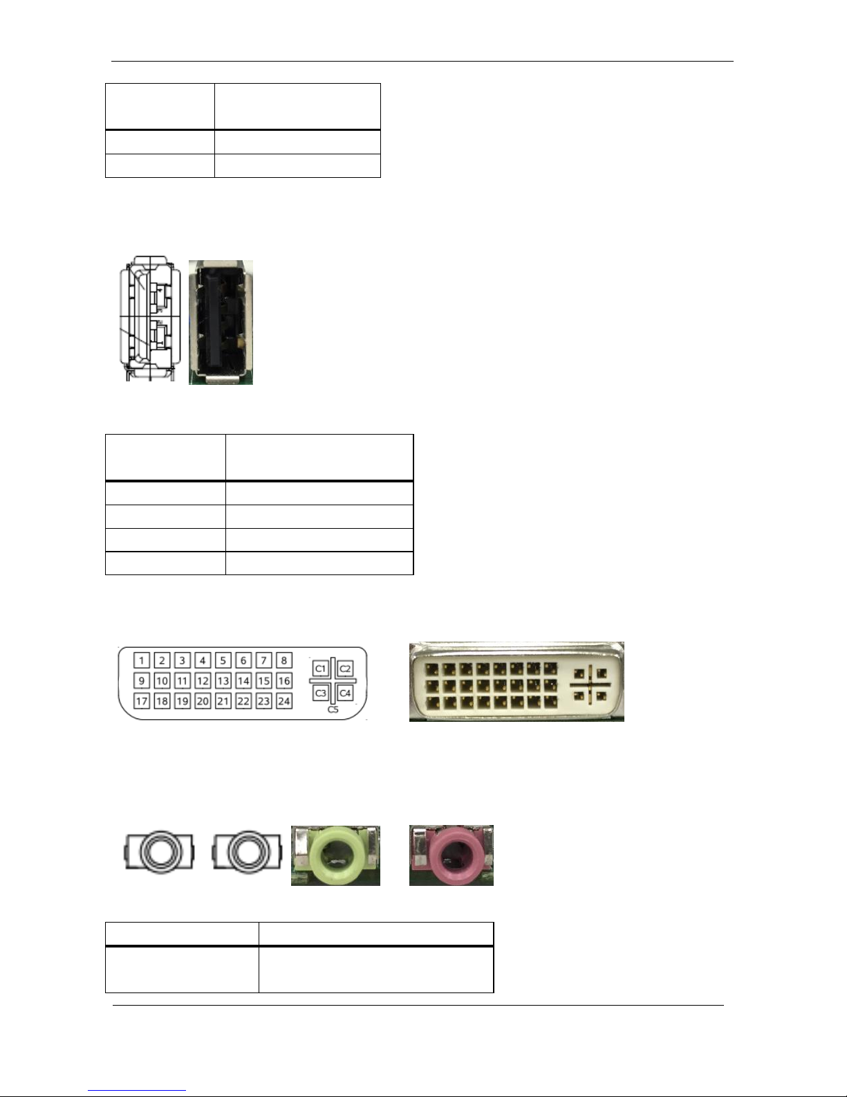
J43 – Power Switch connect
Page 58
49
Pin #
Signal
Description
1
Power ON
2
GND
J44,J45,J46 – External USB 2.0 Port
Pin #
Signal
Description
1
+5V
2
USB_D-
3
USB_D+
4
GND
J47 – External DVI-I Connector
J48 / J49 – External Audio Phone Jack
Audio Jack
Signal Description
J48
Line Out (stereo)
Green
Page 59
50
J49
Microphone (stereo)
Pink
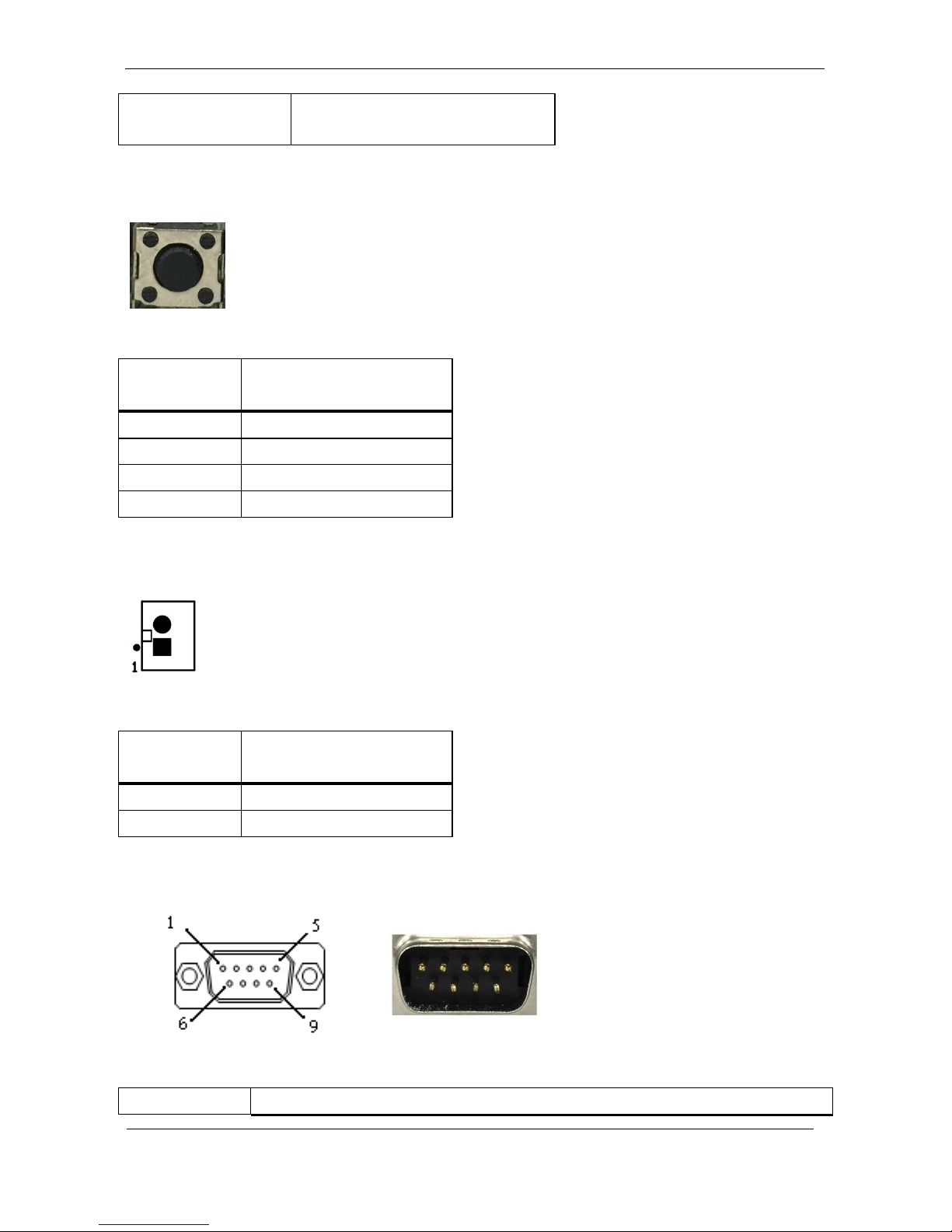
J50 – Reset Button
Pin #
Signal
Description
1
SYS_RESET#
2
GND
3
GND
4
GND
J51 – Reset connector
Pin #
Signal
Description
1
SYS_RESET#
2
GND
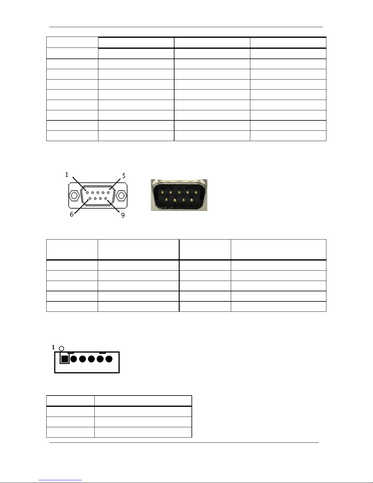
J52 – External COM1 Connector
Pin #
Signal Description
Page 60
51
RS-232
RS-422
RS-485
1
DCD
TX D-
DATA-
2
RXD
TX D+
DATA+
3
TXD
RX D+
--
4
DTR
RX D-
--
5
GND
--
--
6
DSR
--
--
7
RTS
--
--
8
CTS
--
--
9
RI#
--
--
J53 – External COM2 Connector
Pin #
Signal
Description
Pin #
Signal Description
1
DCD
2
RXD
3
TXD
4
DTR
5
GND
6
DSR
7
RTS
8
CTS
9
RI#
10
--
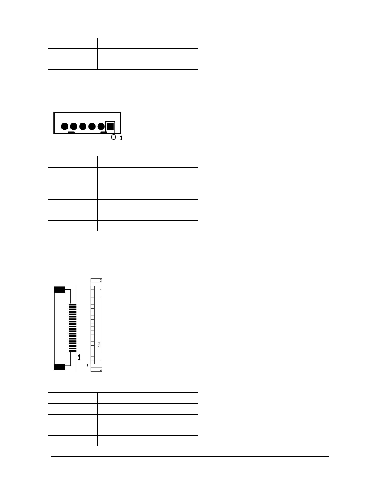
J54/J55*/J56/J57* – Internal USB 2.0 Pin Header
Pin #
Signal Description
1
+5VSB
2
+5VSB
3
Data -
Page 61
52
4
Data +
5
GND
6
GND
*J55/J57 reserve for Mini PCIE x1 share.
J60/J61/J62 – Internal USB 2.0 Pin Header
Pin #
Signal Description
1
+5VSB
2
+5VSB
3
Data -
4
Data +
5
GND
6
GND
*Co-lay with external USB port (J44, J45 and J46).
J58 – External PoE Slot (Option)
Pin #
Signal Description
1
LAN0_MDI0_P
2
LAN0_MDI0_N
3
GND
4
GND
Page 62
53
5
LAN0_MDI1_P
6
LAN0_MDI1_N
7
GND
8
GND
9
GND
10
GND
11
GND
12
GND
13
GND
14
GND
15
LAN0_MDI2_P
16
LAN0_MDI2_N
17
GND
18
GND
19
LAN0_MDI3_P
20
LAN0_MDI3_N
Page 63
54
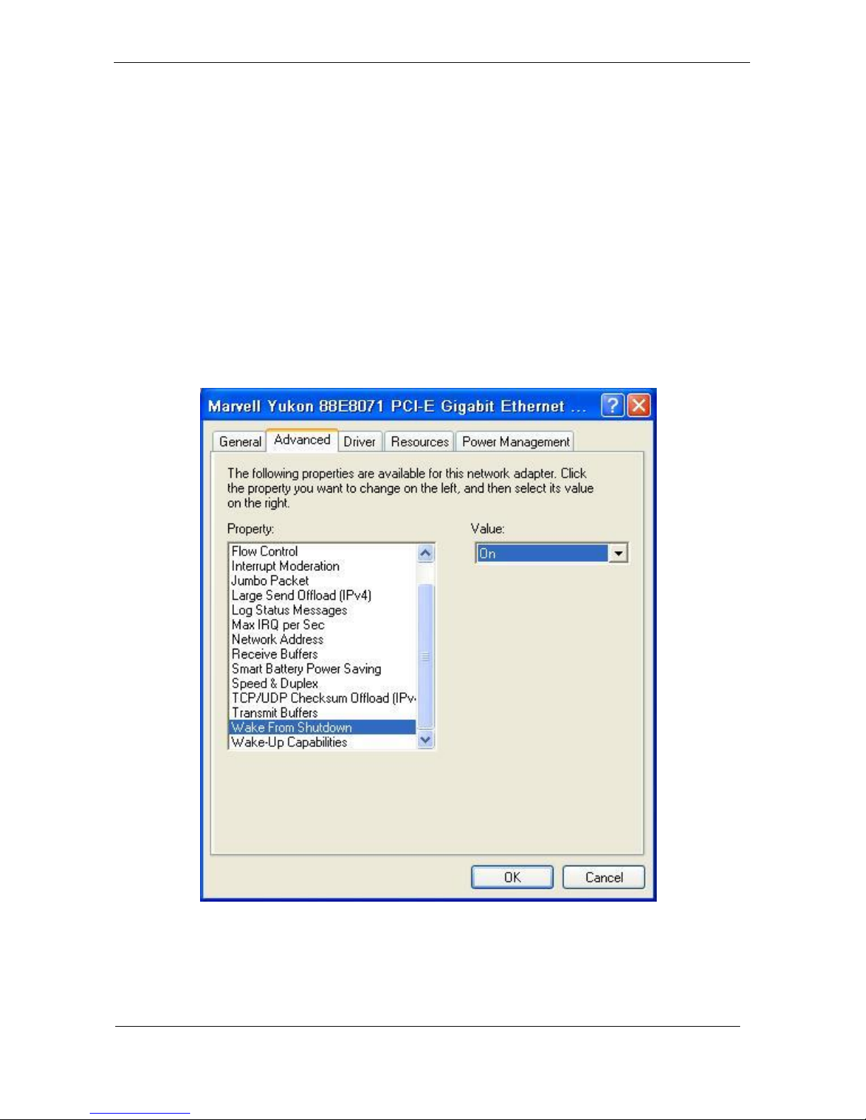
B. Wake UP on LAN Function
Please make sure the AC power is ON before use the
function.
1. Boot into OS (windows XP).
2. In start menu control panel System device manager Network
adapters double click Marvell Yukon 88E8071 Advance Wake
from Shutdown Item select Wake on Magic packet from power
off state.
Please shutdown system and wait for wake on LAN after
finish these procedures.
 Loading...