

Wincomm WLP-7A20 User Manual

WLP-7A20 Series
User’s Manual
P/N: 205G00WLP7A200, Version V1.1
Copyright 2013, ALL RIGHTS RESERVED.
All other brand names are registered trademarks of their respective owner

Copyright Notice
Copyright © 2013
All Rights Reserved.
Printed in Taiwan.
The information contained in this document is subject to change without any
notices.
Acknowledgments
Greeting & Setup
Thank you for purchasing the WLP-7A20 Panel PC. We wish that this unit
will be durable and reliable in providing your needs. Please follow the
instructions below to ensure the unit continues to have high performance
Unpacking
After opening the carton, there will be a unit with an accessory box.
Examine the contents to see if there are damages to the unit and if all
accessories are present.
Setting up
Please read this manual carefully and remember to keep this manual for
future reference.
Safety Instructions & Cleaning
The unit has undergone various tests in order to comply with safety
standards. Inappropriate use may be dangerous. Please remember to
follow the instructions below to insure your safety during the installation and
operating process.
Transporting & Placement of unit
1. When moving the unit on a cart; be very cautious. Quick stops,

III
excessive forces and uneven surfaces may cause the cart to overturn
thus risking the unit to fall to the ground.
2. If the Monitor display unit does fall to the ground, immediately turn the
power off and disconnect cords. Then contact a service technician for
repairs. Continual use of the unit may result cause a fire or electric
shock. Also, do not repair the unit on your own.
3. Having two or more people transporting the display unit is
recommended. In addition, when installing the open frame by
suspending it also requires two or more people.
4. Before suspending the unit, make sure the material used for
suspension is sturdy and stable. If not properly suspended, the display
unit may fall and cause serious injury to people standing nearby as
well as to the unit itself.
5. If you wish to mount the display unit, remember to use only the
mounting hardware recommended by the manufacturer.
Electrical and Power Source Related
1. This Monitor display unit must operate on a power source as shown on
the specification label. If you are not sure what type of power supply
used in the area, consult your dealer or local power supplier.
2. The power cords must not be damaged. Applied pressure, added heat,
and tugging may damage the power cord.
3. The power cord must be routed properly when setup takes place. We
advise that this aspect measure is to prevent people from stepping on
the cords or while the unit is suspended to prevent flying objects from
getting tangled with the unit.
4. Do not overload the AC outlets or extension cords. Electrical shocks or
fires may occur from overloading.
5. Do not touch the power source during a thunderstorm.

IV
6. If your hands are wet, do not touch the plug.
7. Use your thumb and index finger, grip firmly on the power cord to
disconnect from the electrical socket. By pulling the power cord, may
result in damaging it.
8. If the unit is not going to be in use for an extended period of time,
remember to disconnect the unit.
9. Connect the unit to a power source with the same numerical value as
spec. label shown. Please use only the power cord provided by the
dealer to ensure safety and EMC compliance.
Various Factors of Environment
1. Do not insert objects into the openings.
2. Do not have liquids seep into the internal areas of the Monitor display
unit.
3. Having liquids seep in or inserting objects into the unit may result in
electric shocks from taking and/or short circuiting the internal parts.
4. Do not place the Monitor display unit in the presence of high moisture
areas.
5. Do not install the Monitor display unit in a wet environment.
6. Do not place near unit near heat generating sources.
7. Do not place the unit in a location where it will come in contact with
fumes or steam.
8. Remember to keep the Monitor display unit away from the presence of
dust.
9. If water has flow in or seep in, immediately disconnect the open frame
unit. Then contact a service technician for repairs.
Ventilation Spacing
1. Do not cover or block the openings on the top and back sides of the

V
display unit. Inadequate ventilation may cause overheating thus
reducing the lifespan of the unit.
2. Unless proper ventilation is present, do not place unit in an enclosed
area; such as a built-in shelf. Keep a minimum distance of 10 cm
between the display unit and wall.
Cleaning the unit
1. Remember to turn off the power source and to unplug the cord from the
outlet before cleaning the unit.
2. Carefully dismount the unit or bring the unit down from suspension to
clean.
3. Use only a dry soft cloth or clean room wiper when cleaning the LCD
panel or touch screen surface. Use a soft cloth moistened with mild
detergent to clean the display housing.
4. Remember to avoid having liquids seep into the internal components.
Servicing, Repairing, Maintenance & Safety Checks
1. If the unit is not functioning properly, observe the performance level of
the display closely to determine what type of servicing is needed.
2. Do not attempt to repair the Monitor display unit on your own.
Disassembling the cover exposes users’ to high voltages and other
dangerous conditions. Notify and request a qualified service
technician for servicing the unit.
3. If any of the following situations occur turn the power source off and
unplug the unit. Then contact a qualified service technician
i. A liquid was spilled on the unit or objects have fallen into the unit.
ii. The unit is soaked with liquids.
iii. The unit is dropped or damaged.
iv. If smoke or strange odor is flowing out of the open frame unit.

VI
v. If the power cord or plug is damaged.
vi. When the functions of the unit are dysfunctional.
4. When part replacement is needed. Make sure service technician uses
replacement parts specified by the manufacturer, or those with the
same characteristics and performance as the original parts. If
unauthorized parts are used it may result in starting a fire, electrical
shock and/or other dangers.
Battery Installation
Follow below instructions and notice the caution for replacing and disposing
of the RTC Lithium battery CR2032 for safety consideration.
CAUTION:
There is danger of explosion, if battery is incorrectly replaced. Replace
only with the same or equivalent type recommended by the
manufacturer. Dispose of used batteries according to the
manufacturer’s instruction.
The specification is subject to change without notice.
VII
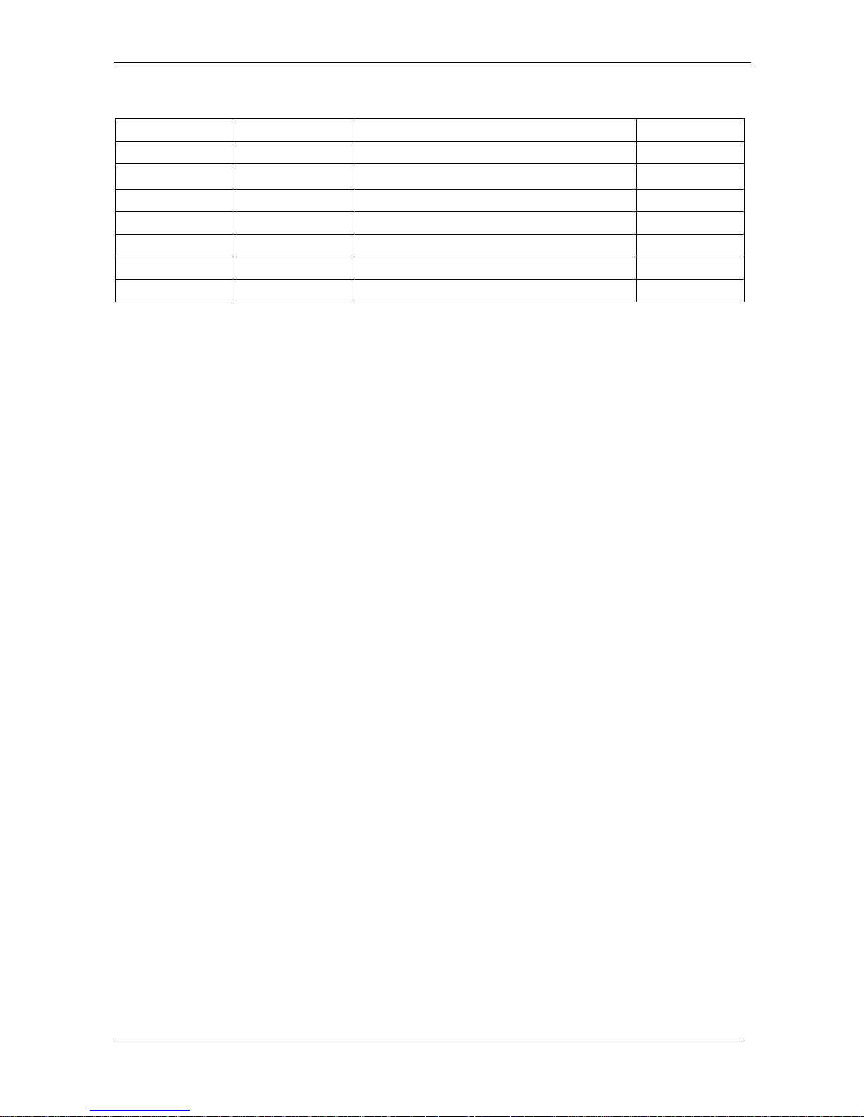
Version Change History
Date
Version
Description
Remark
2013/1/7
V1.0
First release
Cosa
2013/2/1
V1.1
Modify CPU SPEC
Cosa

VIII
Table of Contents
How to Use This Manual ............................................................................... IX
System Overview ........................................................................... 1
System View .................................................................................................... 5
I/O connectors ................................................................................................. 8
VESA mount installation ................................................................................. 8
Panel mount installation ................................................................................ 10
Unpacking ..................................................................................................... 12
Getting Started .............................................................................. 14
Setting up the System .................................................................................... 14
Installing System Software ............................................................................ 14
Installing the Drivers ..................................................................................... 15
BIOS Setup Information ............................................................. 18
Appendix ........................................................................................ 30
A. Jumper settings and Connectors ....................................... 30
B. Wake UP on LAN Function ................................................... 48

IX
How to Use This Manual
This manual is written for the system integrator, PC technician and
knowledgeable PC end user. It describes how to configure your WLP-7A20
Panel PC to meet various operating requirements. The user’s manual is
divided into three chapters, with each chapter addressing a basic concept
and operation of the server board.
Chapter 1: System Overview - presents what you have inside the box
and gives you an overview of the product specifications and basic
system architecture for the WLP-7A20 Panel PC.
Chapter 2: System Installation - describes how to set up the system.
Chapter 3: BIOS Setup Information - specifies the meaning of each
setup parameter, how to get advanced BIOS performance and update
to a new BIOS. Additionally, the POST checkpoint list will give you a
guide for troubleshooting.
The contents of this manual are subject to change without prior notice.
These changes will be incorporated in new editions of this manual.

1
System Overview
System Specification
CPU
Intel® Core™ i5-3317U
Chipset
Intel® BD82HM65 PCH
Audio
Realtek ALC262 audio codec, 2+2 watts power amplifier
LAN
Marvell 88E8071 Giga LAN x 2
Memory
Two 1066/1333 MHz DDR3 SODIMM socket support dual
Channel, non-ECC, up to 8GB
I/O
EC
Serial ATA
SATA 2, 300 MB/s transfer rate x 2
Serial port
RS232,422,485 x 1, RS232 x 5
USB
External USB 2.0 x 4 (Type A)
Internal 3.3V Socket x 3
5V Pin Head x 4 (1 reserved for touch screen)
WDT
Generates system reset; 256 segments, 0, 1, 2…255
sec/min.
BIOS
Brand: AMI
Flash ROM size: 4M bytes
Support RTC wakeup /Wake on LAN /Power on after power
failure/PnP/ACPI/RTC
2
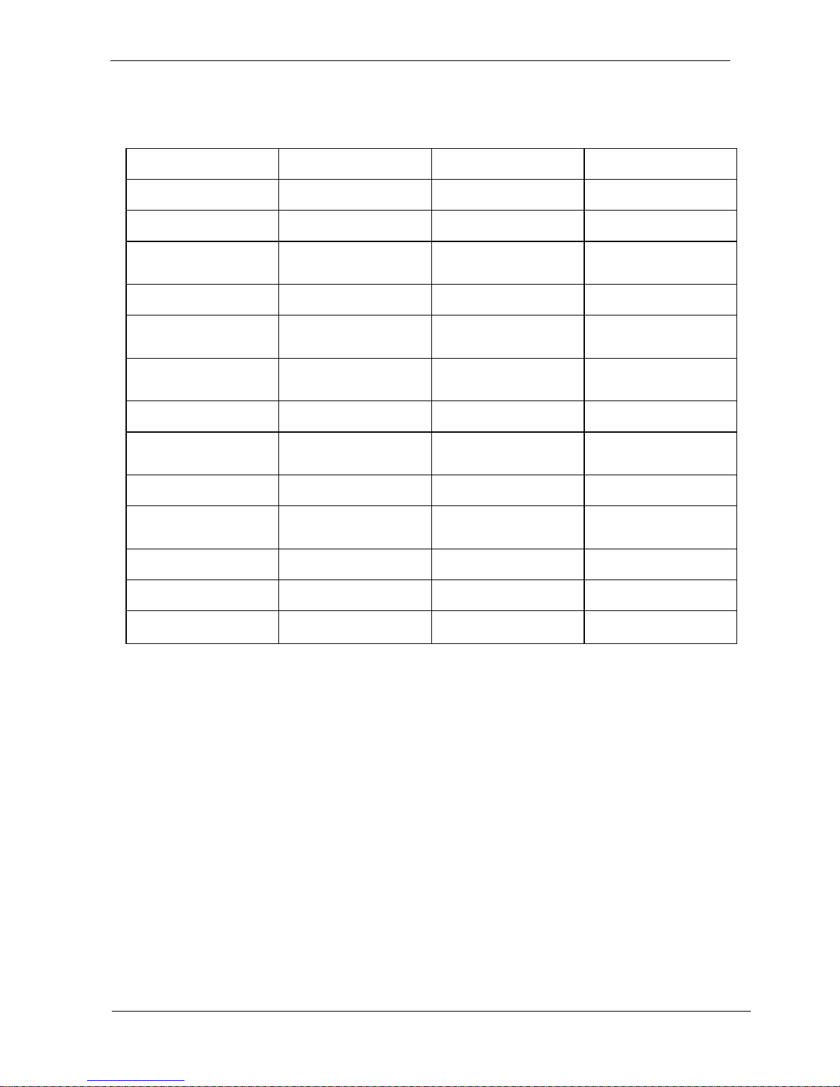
Display
Panel
Size
15”
17”
19”
Brand
LG
AUO
AUO
Model
LB150X02-TL01
G170EG01
G190EG01 V1
Resolution (pixel)
1024x768 XGA
SXGA (1280 x
1024)
SXGA (1280 x
1024)
Number of Colors
16.7M
16.7M
16.7M
View Angle (H/V)
140 / 140
160 / 160
Horizontal 170
Vertical 160
Brightness
(cd/m2)
300
380
350
Contrast Ratio
800:1
800:1
1000:1
Power
Consumption (W)
10.77W
25.8
Interface
8bit LVDS
2ch LVDS
2ch LVDS
Supply Voltage
(V)
3.3 5 5
Backlight
CCFL
4 CCFL
LED
life time<Hrs>
50000hrs
50000hrs
50000hrs
Operating temp.
0-50℃
0~60℃
0-50℃
3
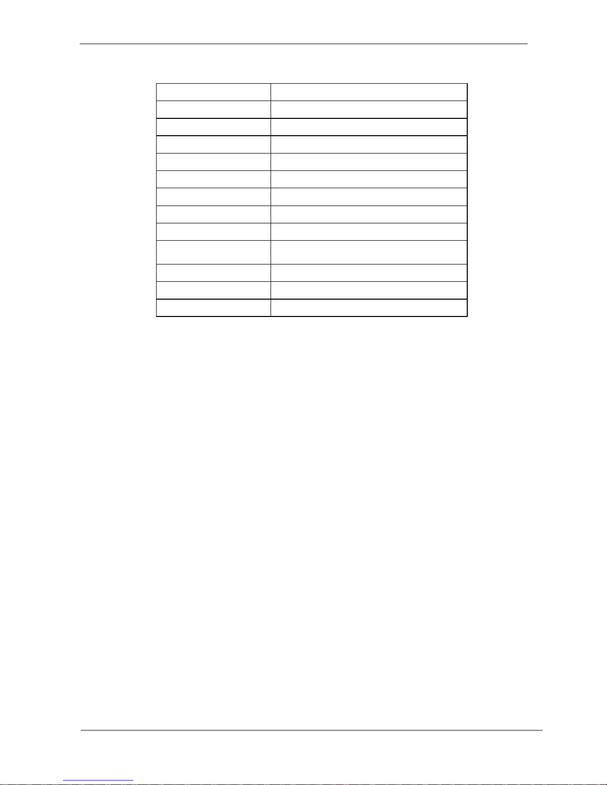
Touch Screen: resistive or capacitive types
AMT
Type
5 wire RES
Glove
Any type glove
Stylus
No Limitation, can use any stylus
Vandal
NA
Interface
USB
Light Transmission
80±3%
Hardness
3H
Glass thickness
1.8mm
Linearity
X≦ 1.5%, Y≦ 1.5%
Active area
212x159.20
Resolution
4096x4096
Lifetime
36 million activations
Touch Controller
RES EETI ,IC8051F321,MCU,TOUCH,28P,0.5MM,SMT,QFN
Storage
HDD
2.5” SATA HDD drive bay x 1 (with anti-vibration
mechanism)
Expansion
Mini-PCIe
52 pin card-edge type compatible to PCI
Express*Base specification 2.0 x 2
External I/O
USB
USB 2.0 x 4
COM
DB-9 x 3 (RS232 x 2, RS232/RS422/RS485 x 1)
LAN
RJ-45 x 2 (Gigabit Ethernet)
Audio
3.5mm phone jack connector * 2 ( Line-out, and Mic-in)
DVI output
DVI-I x 1
4
Power
Power
DC-In connector x 1 (Jack with locker)
Switch
Reset key
LED indicator on
Aluminum bezel
Green: power On/Off
Orange: HDD status
Power Input
DC12V~28V
Power Adapter
AC 90 ~ 264V / 47 ~ 63 Hz / DC output 12V (15”)
AC100~240V / 47 ~ 63 Hz / DC output 12V (17”,19”)
Mechanical & Environmental
Material construction
Front bezel is Aluminum or SECC, others are
SECC enclosure
Aluminum bezel Color
Black / Silver
Front Panel Protection
IP66 / NEMA4X
ID design
Panel mount / Open frame
Operation Temperature
15” & 19”: 12V DC Input 0~50℃
(IEC60068-2-56, air flow cooling)
17”: 12V DC Input 0~45℃
(IEC60068-2-56, air flow cooling)
Storage Temperature
-20~60℃
Operation Relative Humidity
10%~90%, non-condensing
Storage Relative Humidity
10%~90%, non-condensing
Mounting
Panel mount/VESA (75x75)
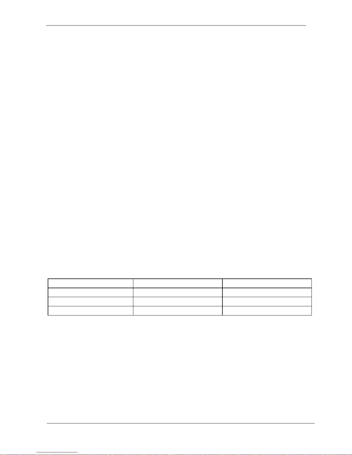
Net Weight
Gross Weight
19”
9
11.7
17”
8.5
11.5
15”
6
8.5
5
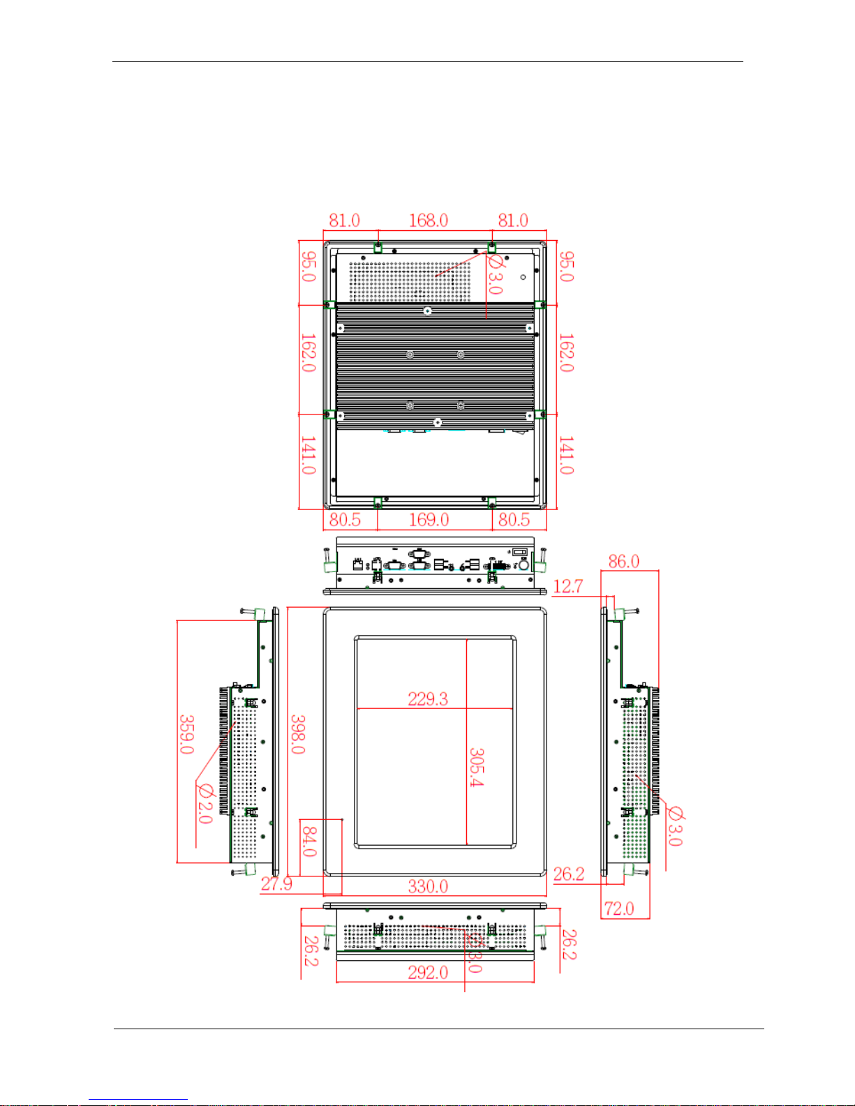
System View
WLP-7A20-15 Outline Drawing (Panel Mount)
6
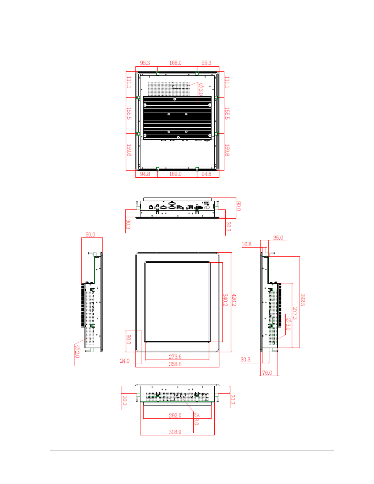
WLP-7A20-17 Outline Drawing (Panel Mount)
7
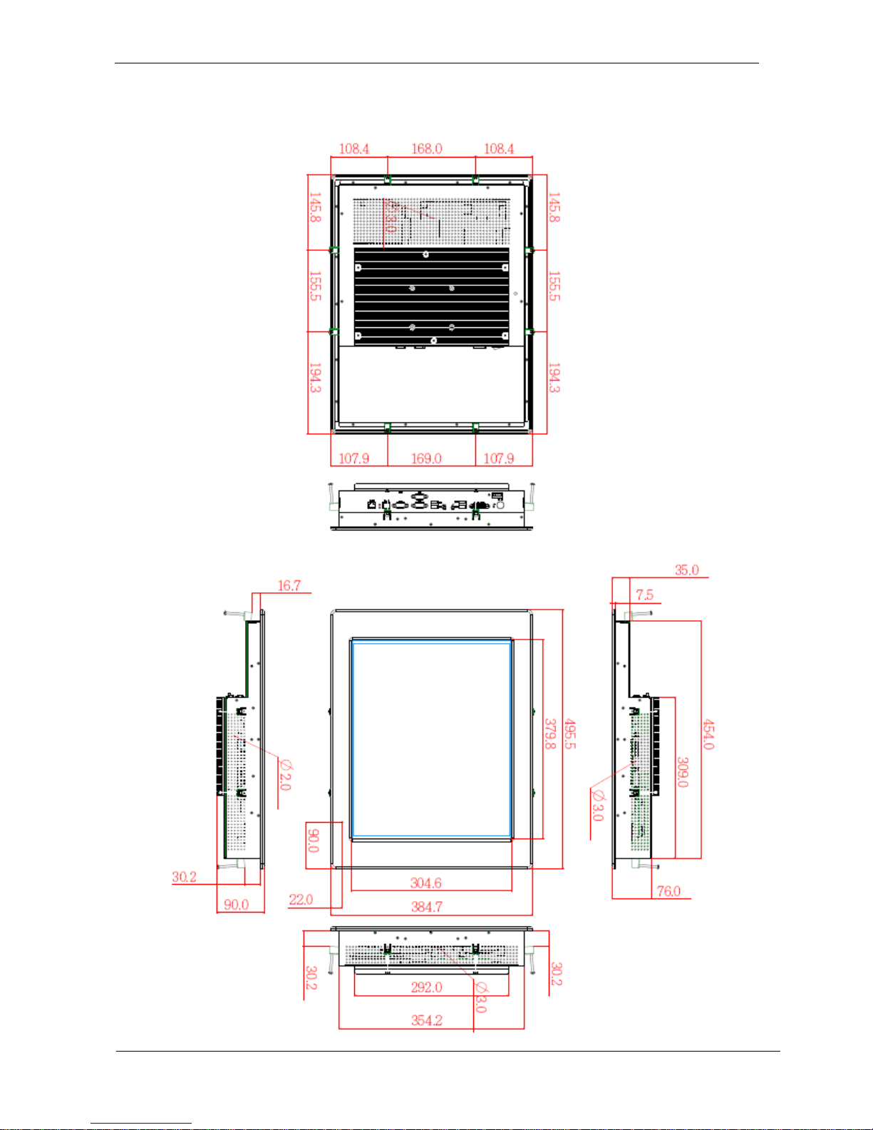
WLP-7A20-19 Outline Drawing (Panel Mount)
8
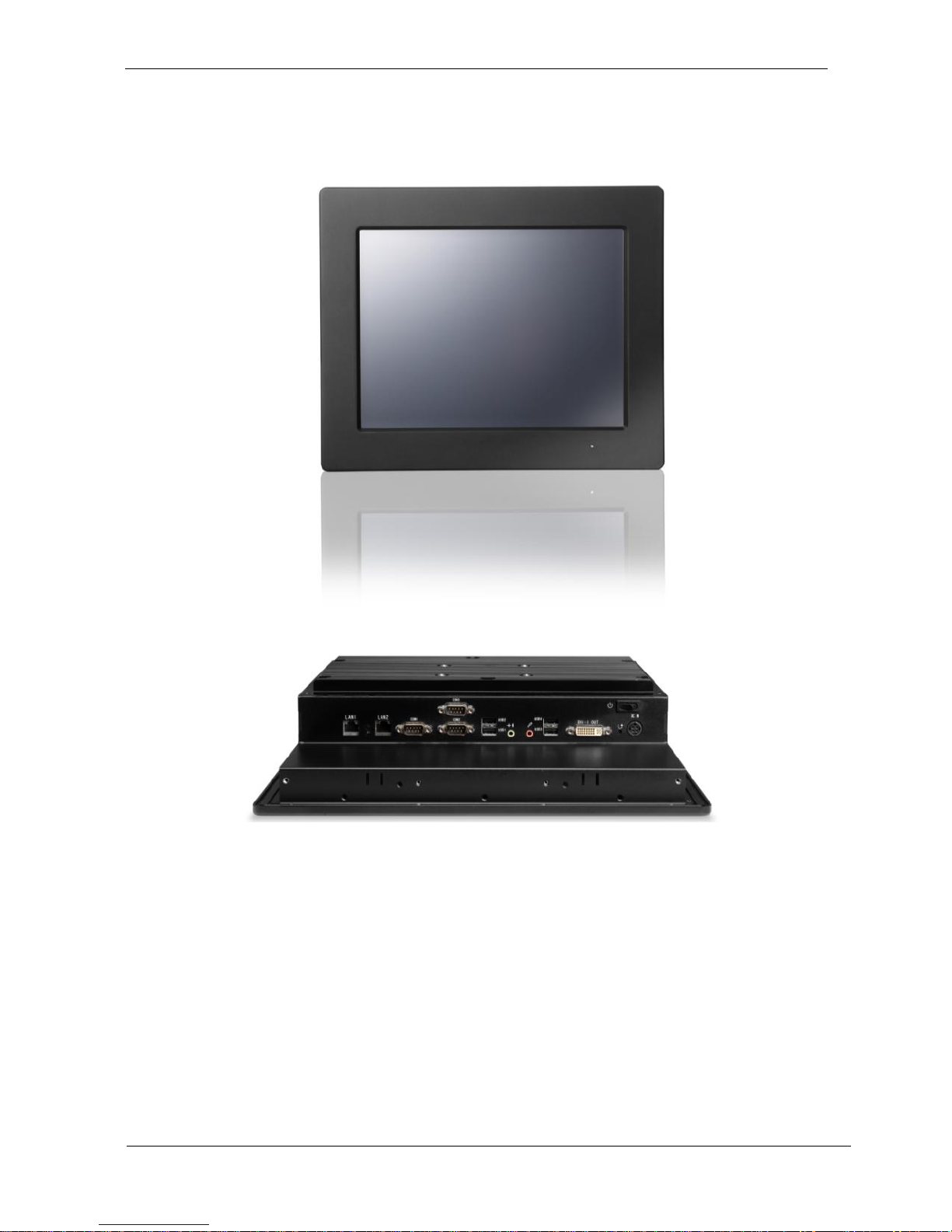
I/O connectors
Note: Share the same place with DVI output, DVI and VGA not simultaneously
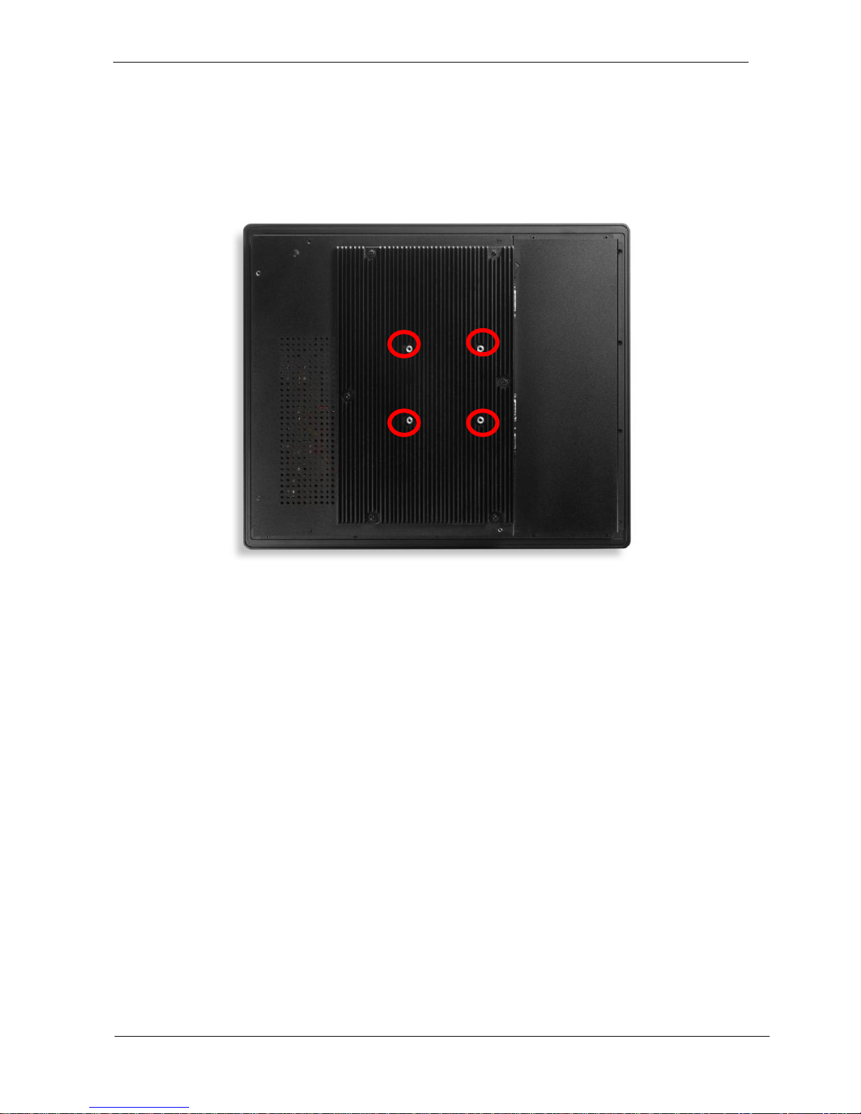
VESA mount installation
Please use the supplied 4 x M4-L10 screws for VESA mounting. And as below
VESA mounting holder is just a diagrammatic drawing. You can choose any
standard VESA 75x75 mm mounting holder to mount our machine.
9
For use only with UL listed Wall Mount Bracket with minimum weight/load
bearing capacity 10 Kg
 Loading...