

Wincomm WLP-7821-17, WLP-7821-19M User Manual

WLP-7821-17/19M
Series
User’s Manual
P/N: 205G00WLP78212, Version V1.0
Copyright © 2011, ALL RIGHTS RESERVED.
All other brand names are registered trademarks of their
respective owners.

Copyright Notice
Copyright © 2011
All Rights Reserved.
Printed in Taiwan.
The information contained in this document is subject to change
without any notices.

III
Acknowledgments
Greeting & Setup
Thank you for purchasing the WLP-7821-17/19M Panel PC. We
wish that this unit will be durable and reliable in providing your
needs. Please follow the instructions below to ensure the unit
continues to have high performance
Unpacking
After opening the carton, there will be a unit with an accessory box.
Examine the contents to see if there are damages to the unit and
if all accessories are present.
Setting up
Please read this manual carefully and remember to keep this
manual for future reference.
Safety Instructions & Cleaning
The unit has undergone various tests in order to comply with
safety standards. Inappropriate use may be dangerous. Please
remember to follow the instructions below to insure your safety
during the installation and operating process.
Transporting & Placement of unit
1. When moving the unit on a cart; be very cautious. Quick stops,
excessive forces and uneven surfaces may cause the cart to
overturn thus risking the unit to fall to the ground.

IV
2. If the Monitor display unit does fall to the ground, immediately
turn the power off and disconnect cords. Then contact a service
technician for repairs. Continual use of the unit may result
cause a fire or electric shock. Also, do not repair the unit on
your own.
2. Having two or more people transporting the display unit is
recommended. In addition, when installing the open frame by
suspending it also requires two or more people.
3. Before suspending the unit, make sure the material used for
suspension is sturdy and stable. If not properly suspended, the
display unit may fall and cause serious injury to people standing
nearby as well as to the unit itself.
4. If you wish to mount the display unit, remember to use only the
mounting hardware recommended by the manufacturer.
Electrical and Power Source Related
1. This Monitor display unit must operate on a power source as
shown on the specification label. If you are not sure what type
of power supply used in the area, consult your dealer or local
power supplier.
2. The power cords must not be damaged. Applied pressure, added
heat, and tugging may damage the power cord.
3. The power cord must be routed properly when setup takes place.

V
We advise that this aspect measure is to prevent people from
stepping on the cords or while the unit is suspended to prevent
flying objects from getting tangled with the unit.
4. Do not overload the AC outlets or extension cords. Electrical
shocks or fires may occur from overloading.
5. Do not touch the power source during a thunderstorm.
6. If your hands are wet, do not touch the plug.
7. Use your thumb and index finger, grip firmly on the power cord
to disconnect from the electrical socket. By pulling the power
cord, may result in damaging it.
8. If the unit is not going to be in use for an extended period of
time, remember to disconnect the unit.
9. Connect the unit to a power source with the same numerical
value as spec. label shown. Please use only the power cord
provided by the dealer to ensure safety and EMC compliance.
Various Factors of Environment
1. Do not insert objects into the openings.
2. Do not have liquids seep into the internal areas of the Monitor
display unit.
3. Having liquids seep in or inserting objects into the unit may
result in electric shocks from taking and/or short circuiting the

VI
internal parts.
4. Do not place the Monitor display unit in the presence of high
moisture areas.
5. Do not install the Monitor display unit in a wet environment.
6. Do not place near unit near heat generating sources.
7. Do not place the unit in a location where it will come in contact
with fumes or steam.
8. Remember to keep the Monitor display unit away from the
presence of dust.
9. If water has flow in or seep in, immediately disconnect the open
frame unit. Then contact a service technician for repairs.
Ventilation Spacing
1. Do not cover or block the openings on the top and back sides of
the display unit. Inadequate ventilation may cause overheating
thus reducing the lifespan of the unit.
2. Unless proper ventilation is present, do not place unit in an
enclosed area; such as a built-in shelf. Keep a minimum
distance of 10 cm between the display unit and wall.
Cleaning the unit
(1) Remember to turn off the power source and to unplug the cord
from the outlet before cleaning the unit.
(2) Carefully dismount the unit or bring the unit down from
suspension to clean.
(3) Use only a dry soft cloth or clean room wiper when cleaning the
LCD panel or touch screen surface. Use a soft cloth moistened
with mild detergent to clean the display housing.

VII
(4) Remember to avoid having liquids seep into the internal
components.
Servicing, Repairing, Maintenance & Safety Checks
1. If the unit is not functioning properly, observe the performance
level of the display closely to determine what type of servicing
is needed.
2. Do not attempt to repair the Monitor display unit on your own.
Disassembling the cover exposes users’ to high voltages and
other dangerous conditions. Notify and request a qualified
service technician for servicing the unit.
3. If any of the following situations occur turn the power source off
and unplug the unit. Then contact a qualified service technician
(a) A liquid was spilled on the unit or objects have fallen into the
unit.
(b) The unit is soaked with liquids.
(c) The unit is dropped or damaged.
(d) If smoke or strange odor is flowing out of the open frame unit.
(e) If the power cord or plug is damaged.
(f) When the functions of the unit are dysfunctional.
4. When part replacement is needed. Make sure service technician
uses replacement parts specified by the manufacturer, or those
with the same characteristics and performance as the original
parts. If unauthorized parts are used it may result in starting a
fire, electrical shock and/or other dangers.
Battery Installation
Follow below instructions and notice the caution for replacing and

VIII
disposing of the RTC Lithium battery CR2032 for safety
consideration.
CAUTION:
There is danger of explosion, if battery is incorrectly replaced.
Replace only with the same or equivalent type recommended
by the manufacturer. Dispose of used batteries according to the
manufacturer’s instruction.
The specification is subject to change without notice.

IX
Version Change History
Date Version Description Remark
2011/04/29 V1.0 First release

X
Table of Contents
How to Use This Manual ............................................................................... XI
System Overview ............................................................................... 1
Introduction ..................................................................................................... 1
System View .................................................................................................... 9
I/O connectors .............................................................................................. 13
Rack mount Installation (For Open frame and Panel mount) ....................... 14
Unpacking ..................................................................................................... 15
Getting Started ................................................................................ 16
Setting Up the System ................................................................................... 16
Installing System Software ............................................................................ 17
Installing the Drivers ..................................................................................... 18
BIOS Setup Information ................................................................ 19
Appendix A. Jumper Setting and Connectors List ...................... 39
Jumpers Location and list .............................................................................. 39
Jumper List .................................................................................................... 40
Jumper Setting ............................................................................................... 40
Connector Definitions ................................................................................... 42
Connectors Location ..................................................................................... 42

XI
How to Use This Manual
This manual is written for the system integrator, PC technician
and knowledgeable PC end user. It describes how to configure your
WLP-7821-17/19M Panel PC to meet various operating
requirements. The user’s manual is divided into three chapters,
with each chapter addressing a basic concept and operation of the
server board.
Chapter 1: System Overview - presents what you have
inside the box and gives you an overview of the product
specifications and basic system architecture for the
WLP-7821-17/19M Panel PC.
Chapter 2: System Installation - describes how to set up
the system.
Chapter 3: BIOS Setup Information - specifies the
meaning of each setup parameter, how to get advanced BIOS
performance and update to a new BIOS. Additionally, the POST
checkpoint list will give you a guide for troubleshooting.
The contents of this manual are subject to change without prior
notice. These changes will be incorporated in new editions of this
manual.

1
System Overview
Introduction
WLP-7821-17/19M Panel PC series are based-on the features of
high performance for Intel Core Dual + 945GME platform with low
power consumption.
WLP-7821-17/19M Panel PC is mainly designed for industrial
automation or digital signage solution with slim and true fanless
feature. With GPIO connector for data collection and device control,
and storage can support internal Compact Flash memory card, or
one 2.5” HDD.
2
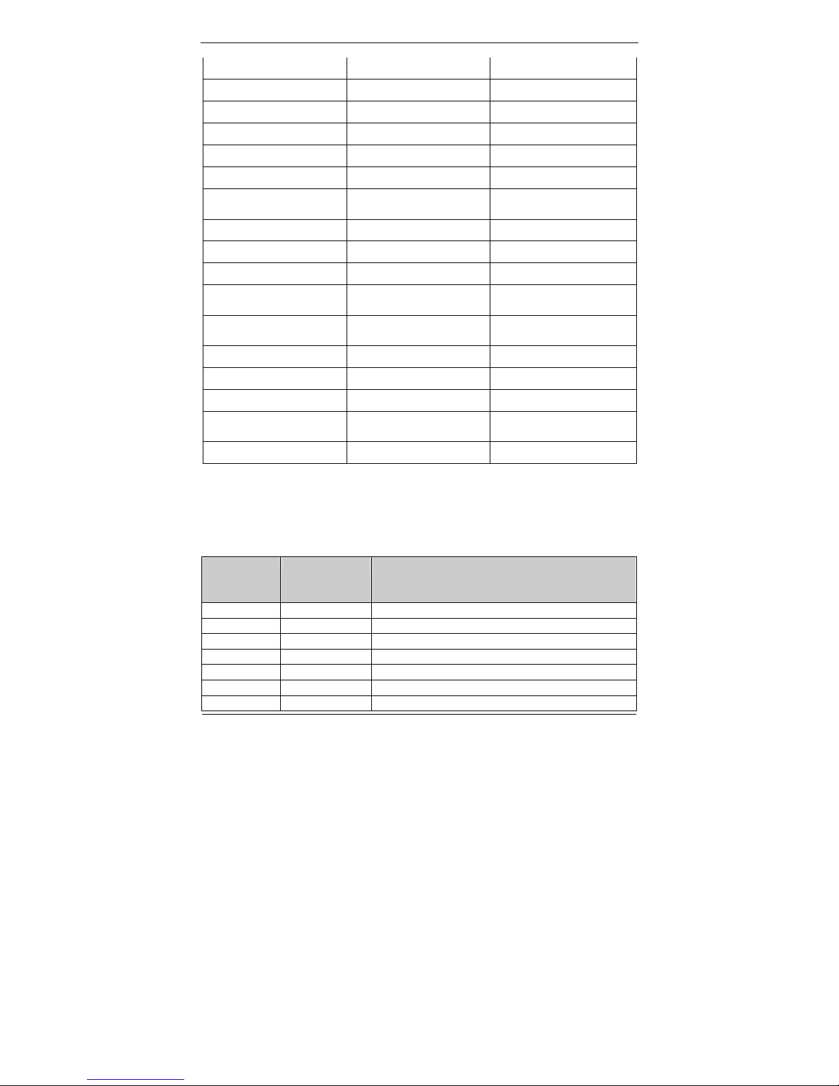
System Specification
System
CPU mPGA479M socket, Supports Intel® Core™ Duo /Solo
processors
CPU List T2600 CD2.16G (31W)
Celeron M 440 1.86G (27W)
Chipset Intel
®
945GME chipset + ICH7M
BIOS 4Mb AMI Flash BIOS
VGA Intel
®
945GME integrated VGA (GMA950)
Audio Realtek ALC655 AC97 Audio Codec, 2+2 watts power
amplifier
LAN 1 x Realtek RTL8111B Gigabit Ethernet
Memory Two DDR2 SODIMM socket supports up to 4GB
I/O ICH7M
Serial ATA Port x 1 with 150 MB/s transfer rate x 1
WDT 1~255 seconds, software programmable
Display
Chipset 945GME integrated graphics utilizing Intel® GMA950
technology
Memory Up to 224MB shared with system memory
Interface DVI-I interface (VGA via converter cable)
Panel 17 AUO G170EG01
19 AUO G190EG01 V0
Size 17” 19"
Model G170EG01 (V0) G190EG01 (V0)
3
Resolution (pixel) SXGA (1280 x 1024) SXGA (1280 x 1024)
Aspect Ratio 5:4 5:4
Active Area (mm) 337.9 x 270.3 376.32 (H) x 301.06(V)
Pixel Pitch (mm) 0.264 0.294
Mode Normally White Normally White
Number of Colors 16.7M 16.7M
Color Saturation
(NTSC %)
72 72
View Angle (H/V) 170 / 160 170 / 160
Brightness (cd/m²) 380 (Typ. Center point) 450 (Typ. Center point)
Contrast Ratio 1000 : 1 (Typ) 1000 : 1 (Typ)
Response Time (ms)
(at 25°C)
5 (Typ) 5 (Typ)
Power Consumption
(W)(typ)
25.2 W 26.71 W
Interface 2ch LVDS 2ch LVDS
Supply Voltage (V) 5 5
Backlight CCFL CCFL
Outline Dimensions
(mm)
358.5 x 296.5 x 15.8 396.0 x 324.0 x 18.5
Weight (g) 2000 (Typ) 2400 (Typ)
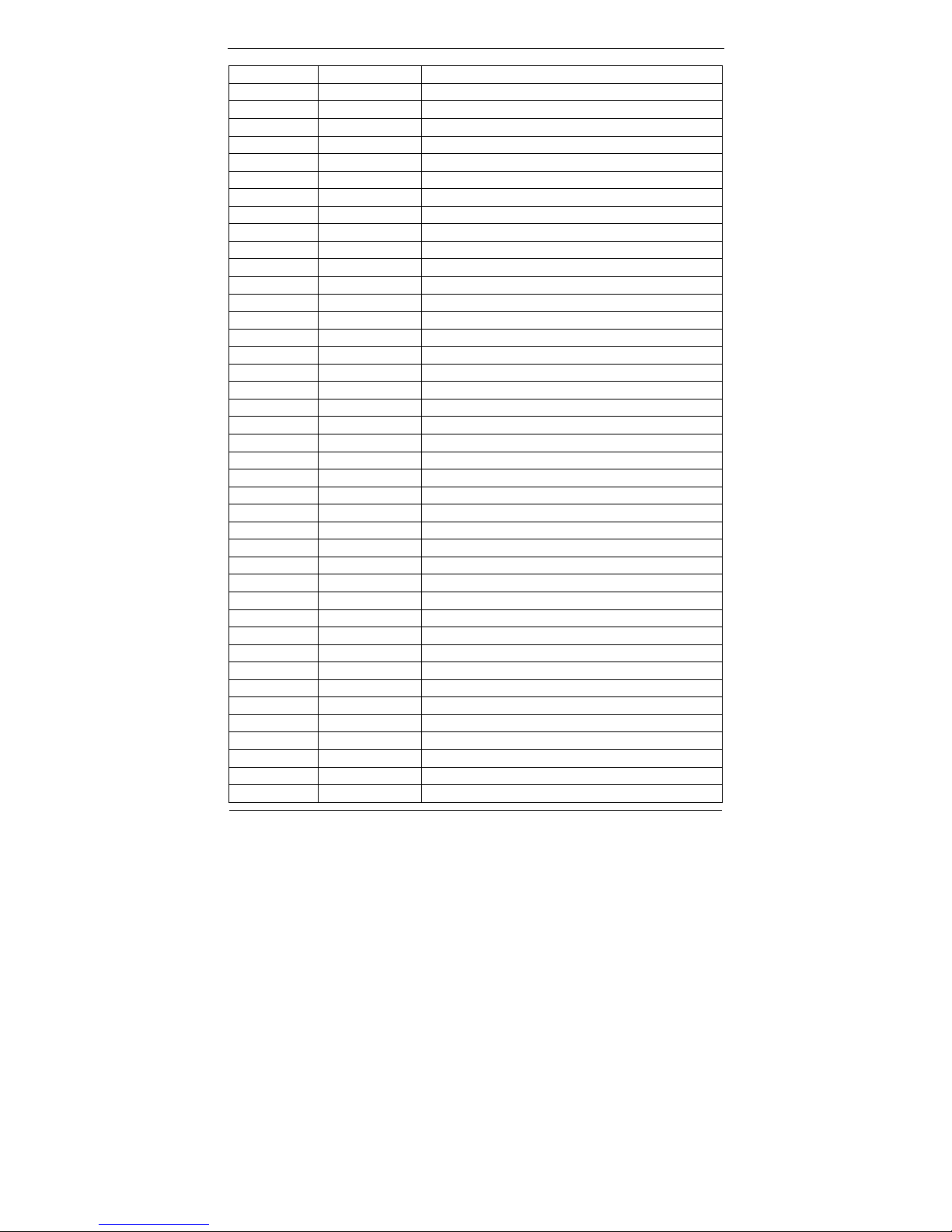
on board VGA Resolution Support Mode List
Windows XP
MODE Colors
Hertz
640*480 256 60,70,72,75,85,100,120
640*480 16-bit colors 60,70,72,75,85,100,120
640*480 32-bit colors 60,70,72,75,85,100,120
800*600 256 56, 60,70,72,75,85,100,120
800*600 16-bit colors 56, 60,70,72,75,85,100,120
800*600 32-bit colors 56, 60,70,72,75,85,100,120
848*480 256 60
4
848*480 16-bit colors 60
848*480 32-bit colors 60
852*480 256 60
852*480 16-bit colors 60
852*480 32-bit colors 60
1024*768 256 60,70,75,85,100,120
1024*768 16-bit colors 60,70,75,85,100,120
1024*768 32-bit colors 60,70,75,85,100,120
1152*864 256 60,75,85,100
1152*864 16-bit colors 60,75,85,100
1152*864 32-bit colors 60,75,85,100
1280*600 256 60
1280*600 16-bit colors 60
1280*600 32-bit colors 60
1280*720 256 60,75,85,100
1280*720 16-bit colors 60,75,85,100
1280*720 32-bit colors 60,75,85,100
1280*768 256 60,75,85
1280*768 16-bit colors 60,75,85
1280*768 32-bit colors 60,75,85
1280*960 256 60,75,85
1280*960 16-bit colors 60,75,85
1280*960 32-bit colors 60,75,85
1280*1024 256 60,75,85,100,120
1280*1024 16-bit colors 60,75,85,100,120
1280*1024 32-bit colors 60,75,85,100,120
1360*768 256 60
1360*768 16-bit colors 60
1360*768 32-bit colors 60
1366*768 256 60
1366*768 16-bit colors 60
1366*768 32-bit colors 60
1400*1050 256 60,75,85
1400*1050 16-bit colors 60,75,85
1400*1050 32-bit colors 60,75,85
1600*900 256 60,75,85,100,120
1600*900 16-bit colors 60,75,85,100,120
1600*900 32-bit colors 60,75,85,100,120
1600*1200 256 60,75,85,100,120
1600*1200 16-bit colors 60,75,85,100,120
1600*1200 32-bit colors 60,75,85
1856*1392 256 60,75
5
1856*1392 16-bit colors 60,75
1856*1392 32-bit colors 60,75
1920*1080 256 60,75,85,100
1920*1080 16-bit colors 60,75,85,100
1920*1080 32-bit colors 60,75,85,100
1920*1200 256 60,75
1920*1200 16-bit colors 60,75
1920*1200 32-bit colors 60,75
1920*1440 256 60,75,85
1920*1440 16-bit colors 60,75,85
1920*1440 32-bit colors 60,75,85
2048*1536 256 60,75
2048*1536 16-bit colors 60,75
2048*1536 32-bit colors 60,75
Touch
Resistive type
Controller Pen mount DMC6000 through USB port (on board)
Screen 17”, 5 wire
19”, 5 wire
Capacitive type
Controller By control board through COM port (Model No.: EXII 7000
RS232 interface control board)
Screen 17 CAP-3M ClearTek™ II 17-8561-203
19 CAP-3M ClearTek™ II 17-8051-203
Touch Screen Application Consideration
Characteristics Resistive
5 wire
Capacitive
Touch Resolution
2048 x 2048
4096x4096
Stylus use possible
beyond finger
No Limitation, can use any stylus Need special conductive stylus

6
Glove use possible Any type glove Only very thin latex glove
Light transmittance
81% ± 3%
90% above
Hardness
≧3H
Mohs 7
Response time 20 ms 3 ms
Front Panel
Protection –IP65
V V
Touch screen Life Typically fewer than 2 million
touches, Constant flexing will
degrade accuracy over time
Specified to over 200 million
touches Coatings can wear
Storage
HDD 2.5” SATA HDD drive bay x 1 (with anti-vibration mechanism)
CF 1 x bootable Compact Flash slot for CF type I/II storages
Expansion
Mini-PCI 1 x 32-bit Mini-PCI socket
External I/O
DVI DVI-I digital video connector x 1
USB USB 2.0 x 4
COM DB-9 x 4 (RS-232 x 3, RS-232/422/485 x 1)
LAN RJ-45 x 1 (Gigabit Ethernet)
KB/Mouse PS/2 Keyboard & Mouse x 1
Audio Line-in, Line-out, and Mic-in audio jacks
Mechanical & Environmental
Material Aluminum
Color Black/Silver
Front Panel Protection IP65
ID design 1. Panel mount / Chassis housing for option
2. Open frame
Operating Temperature 0~40℃ (Fanless,
Open frame and Panel mount at airtight)
7
Storage Temperature -20~60℃
Operating Humidity 10%~90%, non-condensing
Storage Humidity 10%~90%, non-condensing
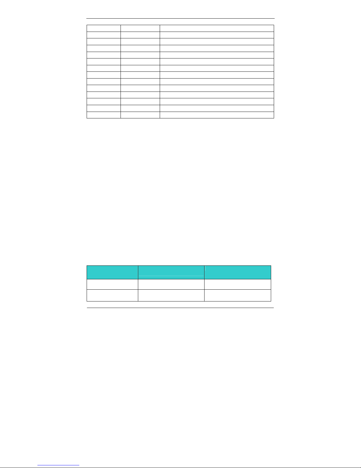
Dimension
Description WLP-7821-17-RES/CAP WLP-7821-19-RES/CAP
Dimensions
(L) x (W) x
(H)
Unit:mm
477.2x362x78 (panel
mount)
438.2x339.5x73(openframe)
514.7x396x79.5 (panel
mount)
475.7x373.5x73.5(openframe)
Weight
Unit: Kg
8.8 (panel mount)
7.4 (openframe)
9.8 (panel mount)
8.0 (openframe)
Mounting VESA mount 75/100/Panel mount /Wall mount
Kensington lock hole
Power
Power Input DC12V~28V
Power Adaptor AC90 ~ 264V / 47 ~ 63 Hz/ DC input 12V
Power DC-In connector x 1
Switch ATX power switch & RESET switch
Indicator Power and HDD indicator (Front LED color: Power:
Green / Orange: HDD accessing)
Regulatory
FCC-A, CE (EMC/LVD), VCCI, UL/cUL
Shock
Operating: 15g/0.53 oz, 11 ms, half sine wave
Non-operating: 50g/1.76 oz, 11 ms, half sine wave
Vibration
Operating: 5 ~ 17 Hz , Amplitude:0.1”
17 ~ 500Hz , Acceleration:1.0G

8
Non-operating: 10~55Hz/0.15g, 55~500Hz/1.5g
Drop
Non-operating:3 Feet height free drop still survive, (test surface: concrete,
base unit only)
Options
Wireless LAN
SSD/CF
9
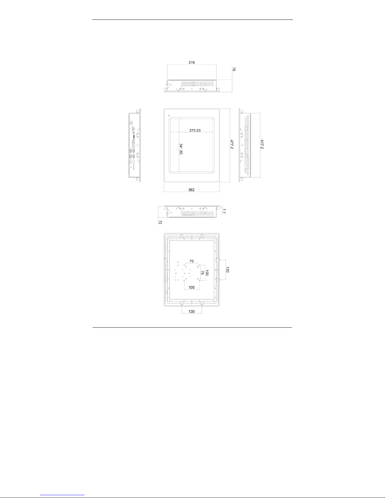
System View
WLP-7821-17M –RES/CAP Panel Mount Outline Drawing
 Loading...