

Wincomm WAF2400-1000L Installation And Operation Manual
Product code WAF2400-1000L
Antenna Amplifier, 2.4-2.4835 GHz, 0.250 W Output
Caution: For use only with the provided Lucent Technologies ORiNOCO Model: PC24E-00-FC WaveLAN 2.4 GHz
wireless card with FCC ID: IMRWLPC24. Use of other radio transmitters with this amplifier may cause interference, and
is a violation of FCC Rules.
The bi-directional RF amplifier greatly increases usable signal transmission range by increasing receiver sensitivity and
compensating for various line losses (in the feeder, connectors and cable) and signal losses due to electromagnetic
radiation.
Receiver Performance
Maximum Gain: 22dB
Noise Figure: 2.8 dB
Frequency Response: +/- 0.5 dB over operating range
Output Saturation RF Power: 10 mW
Transmitter Performance
Automatic Gain Control
Maximum Gain: 30 dB
Intput RF Power: 0.5 - 100 mW
Maximum Output RF Power: 250 mW
Input/Output Impedance: 50 Ohm
Switching Power: 0.2 - 0.4 mW
Switch Delay Time: 0.5 - 0.8 mks
Input/Output Connectors: N – Type Female
Operating Temperature: -50°C - +50°C
Power Supply Specifications
Input Voltage: 110 - 240 VAC 50/60 Hz
Output Voltage/Power: 12 VDC / 10 W
DC Power Injector:
- Radio Modem Connector: N – Type Female
- Amplifier Connector: N – Type Female
- 12 VDC Power Input Connector: BNC - Type Female
Filter Specifications
Filter Bandwidth: 100 MHz
RF Range: 2.4 - 2.5 GHz
Insertion Loss in 2.4-2.5 GHz: 0.5 dB
Signal Attenuation: 50 dB @ 2 GHz
Signal Attenuation: 50 dB @ 3 GHz
Physical Characteristics
Amplifier Weight: 2.0 lbs (0.9 kg)
Amplifier Dimensions: 12 in x 4.8 in x 2.8 in (300mm x 120mm x 70mm)
Power Supply Weight: 1.0 lb (0.45 kg)
Power Supply Dimensions: 12 in x 4.8 in x 2.8 in (300mm x 120mm x 70mm)
1

FCC Notice: Use of RF amplifiers in the United States is subject to FCC regulations. This device
cannot be used with any transmitter other than the one it has been supplied with. This device
requires professional installation. User is responsible for compliance with applicable laws and
regulations
Installation and Operation Manual
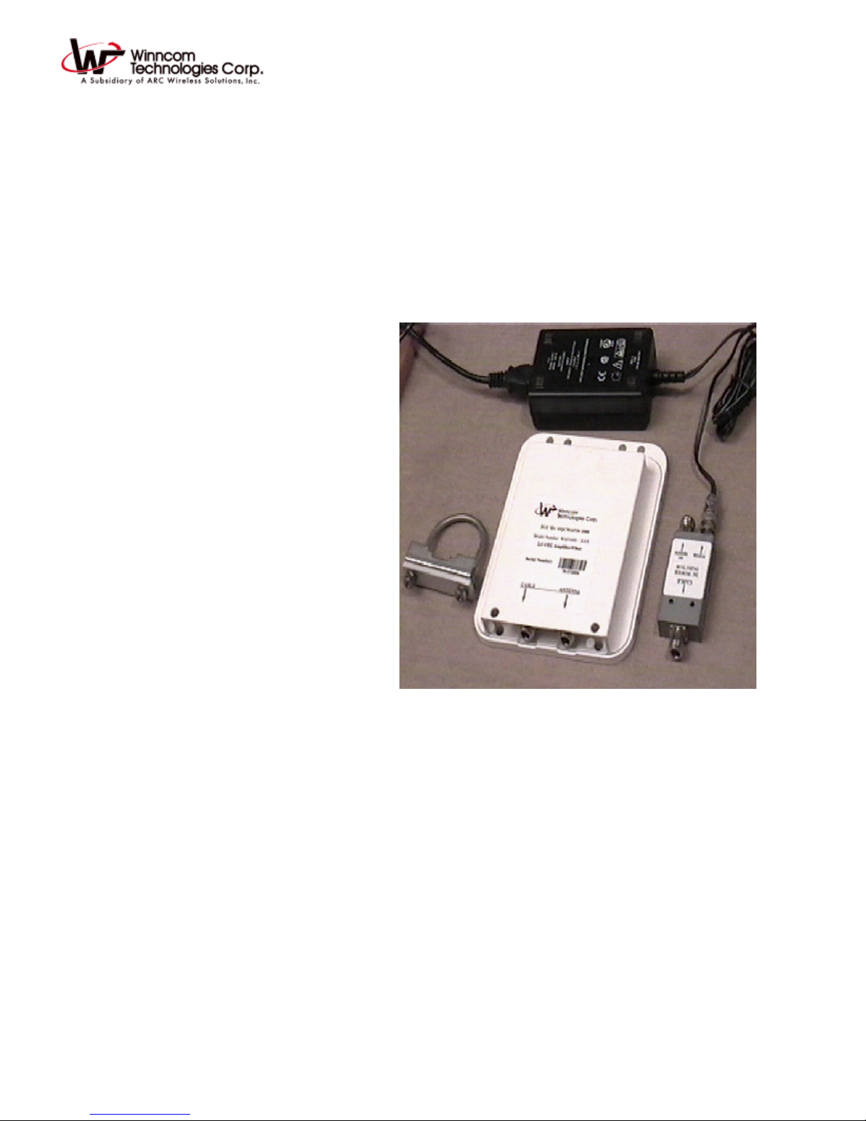
The entire transceiver station assembly consists of seven main components:
1. Low-noise receive amplifier, transmit amplifier, bandpass filter, and switching control unit assembled in a
sealed enclosure.
2. DC power injector. The power injector connects to the transmitting device and the amplifier assembly with
a 10 ft. RF 50 Ohm coaxial cable.
3. 110-220 VAC Power supply with DC output BNC connector.
4. 10 ft. 50 ohm RF cable assembly.
5. One of 4 antenna models (omni, yagi, dish) as appropriate for installation.
6. Lucent Technologies Model: PC24E-00-FC WaveLAN 2.4 GHz wireless PCMCIA card.
7. Computer system.
The amplifier kit contains the following equipment:
Item Quantity
Amplifier 1
DC Power injector 1
Power supply 1
Mounting brackets 1
U-bolt 1
Installation Instructions
Important Notice:
Read the following installation instructions and all warnings carefully prior to installing the amplifier.
Failure to follow installation instructions or tampering with the amplifier or the power supply will void
the warranty.
2
 Loading...