

Page 1

INSTALLATION INSTRUCTIONS
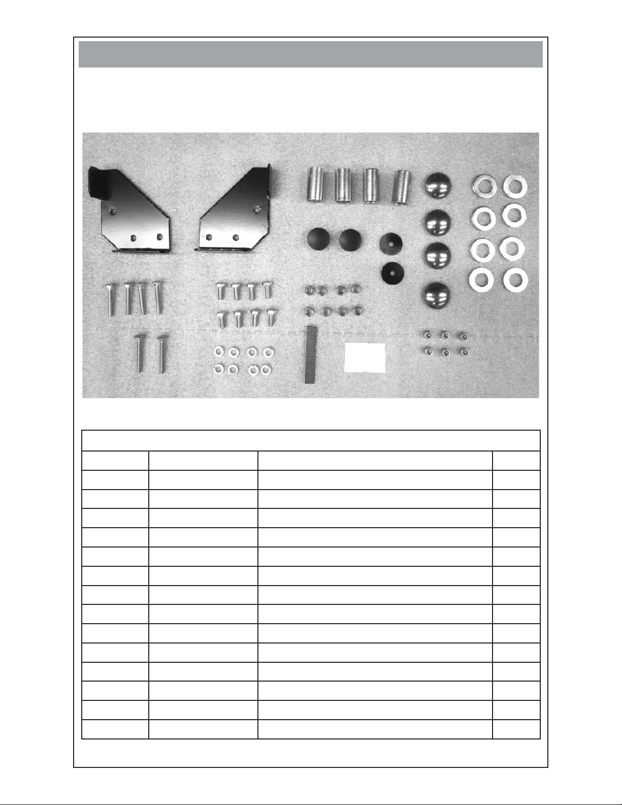
4 WHEEL DOLLY KIT
1
6
REF. # PART # DESCRIPTION QTY.
1 SEE NOTE BELOW 43657-003 Pneumatic Wheel & Tire 4
2 61857-003 Handle 1
3 15775-005 Axle Bracket 1
4 15775-007 Axle Bracket 1
5 64326-020 Axle 2
6 16343-000 Axle Protector 4
7 16199-104 Parts Bag 1
2
3
5
COMPONENT LIST
7
4
NOTE: Foam Filled Wheel & Tire is part # 43657-004
Hard Rubber Wheel & Tire is part # 43657-005
112111-00 16199-010I
Page 2
STEP 1
Open hardware bag and account for all hardware and fasteners.
•
FASTENERS & MISC. COMPONENTS
(not shown in actual size)
8
13
18
14
19
9
15
20
HARDWARE & FASTENER LIST
16
10
17
11
12
21
REF # PART # DESCRIPTION QTY
8 300066-3S Right Handle Support 1
9 300066-4S Left Handle Support 1
10 64688-007 Axle Stub 4
11 64327-000 Hubcap 4
12 1178-000 Flat Washer 8
13 56842-004 1/4” - 20 X 1 3/4” Bolt 4
14 467-000 5/16” - 18 X 3/4” Bolt 8
15 458-000 5/16” Nut 8
16 93402-002 Hole Plug 2
17 96286-006 Nylon Washer 2
18 56842-005 1/4” - 20 X 2” Bolt 2
19 480-000 5/16” Split Lock Washer 8
20 62912-000 Foam Strip 1
21 47517-000 1/4” Nylock Nut 6
212111-00 16199-010I
Page 3

STEP 2
Cut the foam strip (ref. 20) in half using a scissors. Apply to the underside of the
•
handle supports (ref. 8 & 9). Insert hole plugs (ref. 16) into the ends of the handle.
•
Bolt left and right handle supports (ref. 8 & 9) to the cradle using hardware (ref. 13,
21). Place the nylon fl at washer (ref. 17) between the handle supports and handle
then attach handle (ref. 2) using hardware (ref. 18, 21). Tighten the nylock nuts
(ref. 21). Do not over-tighten such that the handle will move freely.
STEP 3
•
Remove the generator from the pallet or box and block generator up 8 to 10 inches to gain access to the bottom of the cradle assembly. A lifting jack or hoist may
also be used if available.
312111-00 16199-010I
Page 4

STEP 4
Bolt axle bracket (ref.3) on the generator end of the cradle and axle bracket (ref.4)
•
to the engine end of the cradle using hardware (ref. 14, 19, 15). Make sure the
axle brackets are on the inside of the cradle cross-members.
GENERATOR END
OF CRADLE
STEP 5
•
Remove and discard axle protectors (ref. 6). Tap one hubcap (ref.11) onto axle
(ref. 5) using a rubber mallet. Slide washer (ref. 12), wheel (ref. 1), washer (ref.
12) and axle stub (ref. 10) onto axle (ref. 5). Then slide one assembly through
axle bracket. Place other spacer, washer, wheel and washer on axle. Repeat for
the other axle bracket.
•
Remove the blocks from under the cradle.
•
Tap the last two hubcaps (ref. 11) on the axles. NOTE: Do not tap too hard as you
may dent the hubcaps.
GENERATOR END
OF CRADLE
Winco Inc.
Service Dept.
507-357-6831
412111-00 16199-010I
 Loading...