

Page 1
INSTALLATION INSTRUCTIONS
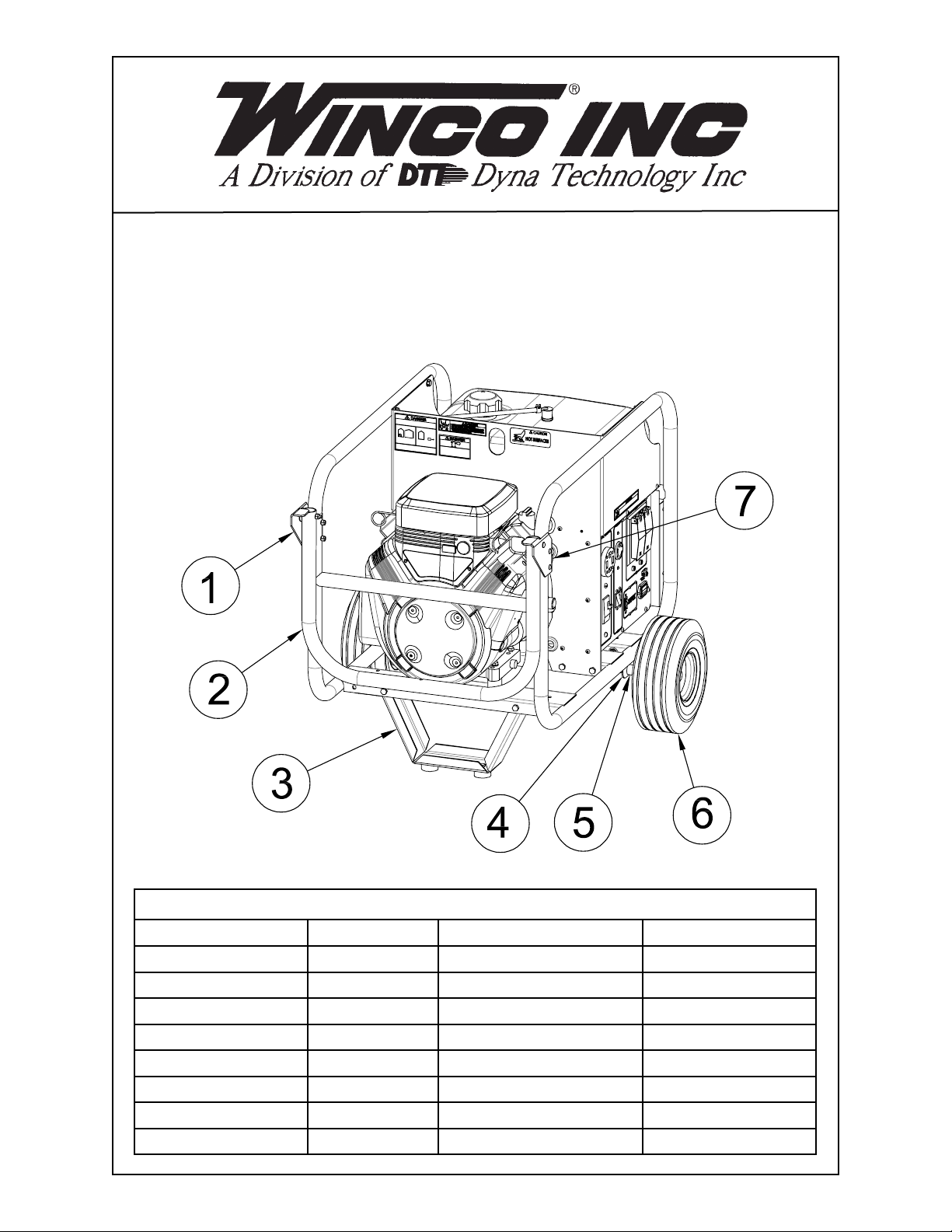
2 WHEEL DOLLY KIT
MODEL WC10000VE
COMPONENT LIST
REF. # PART # DESCRIPTION QTY.
1 300066-4 Left Handle Support 1
2 61857-006 Handle 1
3 16205-004 Foot 1
4 15775-012 Axle Bracket 2
5 64326-015 Axle 1
6 43657-003 Wheel & Tire 2
7 300066-3 Right Handle Support 1
16199-120
Parts Bag 1
112038-02 16199-020I
Page 2
STEP 1
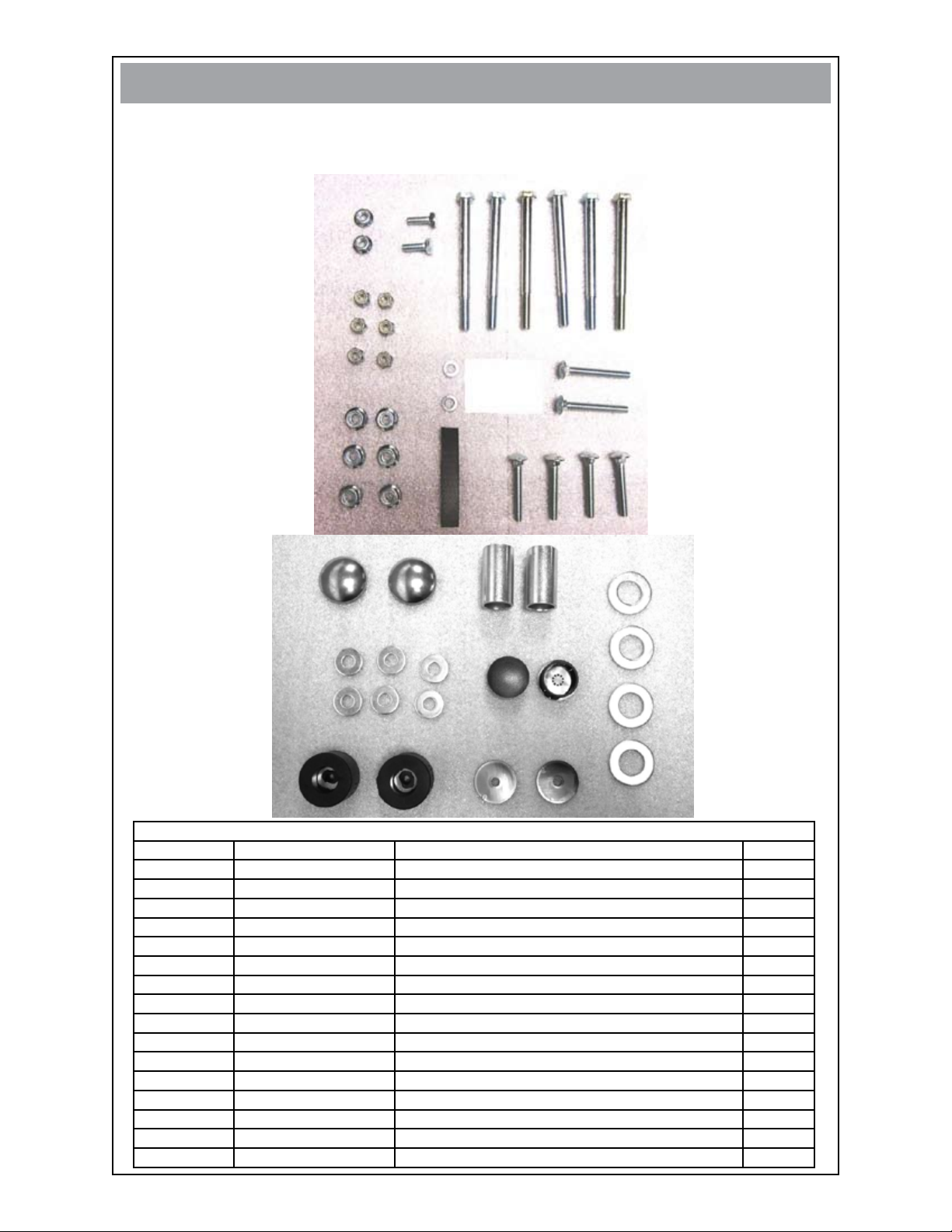
Open hardware bag and account for all fasteners and components.
•
FASTENERS & MISC. COMPONENTS
(not shown in actual size)
10
14
21
9
11
8
20
13
12
16
17
15
22
23
18
FASTENER & COMPONENT LIST
REF # PART # DESCRIPTION QTY
8 56842-005 1/4” X 2“ Carriage Bolt 2
9 47517-000 Nylock Hex Nut 6
10 16248-000 1/4“ Flange Nut
11 479-000 1/4“ Split Lock Washer 2
12
13 16249-000 5/16” Flange Nut
14
15
16 1178-000
17
18 20191-000
19
20 62912-000 Foam Strip 1
21 91672-011 5/16” X 4” Bolt
22 526-000 Flat Washer 6
23 93402-002 Hole Plug 2
56842-004 1/4” X 1 3/4 “ Carriage Bolt 4
466-000 1/4” X 3/4” Bolt 2
64688-007 Spacer 2
Flat Washer 4
64327-000 Hub Cap 2
Shock Mount 2
96286-006 Nylon Flat Washer 2
19
2
6
6
212038-02 16199-020I
Page 3

STEP 2
Remove the generator from the pallet and block generator up 8 to 10 inches to
•
gain access to the botton of the cradle assembly. A lifting jack or hoist may also
be used if available.
STEP 3
Bolt shock mounts (ref. 18) to the bottom of the foot bracket (ref. 3) using hard-
•
ware (ref. 14, 11 & 10). Place foot bracket (ref. 3) into the front cross channel of
the cradle and bolt on with hardware (ref. 22, 21, 13). Place both axle brackets
(ref. 5) into the rear cross channel of the cradle and bolt on with hardware (ref. 22,
21, 13).
312038-02 16199-020I
Page 4

STEP 4
Install hole plugs (ref. 23) into ends of handle (ref. 2). Cut the foam strip (ref. 20)
•
in half using a scissors. Apply to the underside of the handle supports (ref. 1 & 7).
•
Bolt left and right handle supports (ref. 1 & 7) to the cradle using hardware (ref. 8,
9). Attach handle (ref. 2) using hardware (ref. 12, 19, 9). Tighten the nylock hex
nuts. Do not over-tighten so that the handle will move freely.
STEP 5
Tap one hubcap (ref.17) onto axle using a rubber mallet. Slide washer (ref. 16),
•
wheel (ref. 6), washer (ref. 16) and spacer (ref. 15) onto axle (ref. 4). Then slide
assembly through the two axle brackets. Place other spacer, washer, wheel and
washer on axle and lower to the ground. Place the other hubcap on the axle and
tap into place with a rubber mallet.
412038-02 16199-020I
 Loading...