

Winco W6010DI, W6010DE, W6010DJ, W6010DK Installation And Operator's Manual
W6010DE/I, J & K
GENERATOR
INSTALLATION AND
OPERATORS
WINCO INC. 225 S. CORDOVA AVE. LE CENTER, MN 56057
MANUAL
SALES DEPT. 507-357-6821
SERVICE DEPT. 507-357-6831
www.wincogen.com

TABLE OF CONTENTS
SAVE THESE INSTRUCTIONS 3
SPECIFICATIONS 3
GENERATOR
ENGINE
TESTING POLICY 3
SAFETY 4
IMPORTANT SAFETY INSTRUCTIONS
ANSI SAFETY DEFINITIONS
INTRODUCTION 5
INTENDED USES
RESTRICTED USES
UNIT CAPABILITIES 5
GENERATOR CONNECTIONS
STARTING ELECTRIC MOTORS
PREPARING THE UNIT 6
UNPACKING
LUBRICATION
OIL RECOMMENDATIONS
DIESEL FUEL
BATTERY INSTALLATION 7
LIFTING EYE INSTALLATION 8
SERVICING BATTERIES
BATTERY CHARGING
INITIAL START UP 9
BASIC OPERATION
STARTING HINTS
STOPPING
CONNECTING THE LOADS 10
APPLYING THE LOADS
GROUNDING
WIRING
ENGINE CARE 12
MAINTENANCE SCHEDULE
CHANGING THE OIL
CHECKING THE OIL LEVEL
AIR FILTER
GENERATOR CARE 13
EXERCISING THE GENERATOR
GENERATOR MAINTENANCE
CLEANING
TROUBLESHOOTING 14
CONTROL PANEL WIRING DIAGRAM 15
36 MONTH LIMITED WARRANTY 16
OPM-107
2
REV C

COPY YOUR MODEL AND SERIAL NUMBER HERE
No other WINCO generator has the same serial number as yours.
If you should ever need to contact us on this unit, it will help us to
respond to your needs faster.
MODEL __________________________________________________
SERIAL NUMBER _________________________________________
PURCHASE DATE _________________________________________
DEALER NAME ___________________________________________
DEALER PHONE # ________________________________________
SAVE THESE INSTRUCTIONS
This manual contains important instructions that should be followed
during installation and maintenance of the generator. Read and
understand all instructions in the manual before starting and operating
the generator.
SPECIFICATIONS
GENERATOR
Model W6010DE/I, J, & K
Starting Watts 6,010
Running Watts 5,160
Volts 120/240
Starting Amps 50/25
Running Amps 43/21.5
Generator Manufacturer Mecc Alte Spa
Generator Model Number S20FS-160/A
Part Number 351836-1
Rotor Resistance 6.57 Ohms
Stator Resistance 0.124 Ohms
Cap Winding Resistance 0.60 Ohms
Capacitors 31.5 mF
Capacitor Part Number 300323-112
ENGINE
Engine Manufacturer Kohler
Engine Model Number KD440
Fuel Type Diesel
Oil Capacity 51.2 oz. (1.6 qts)
USING THIS MANUAL
Congratulations on your choice of a WINCO generator. You have
selected a high-quality, precision-engineered generator designed and
tested to give you years of satisfactory service.
To get the best performance from your new generator, it is important
that you carefully read and follow the operating instructions in this
manual.
Should you experience a problem please follow the “Troubleshooting
Tables” near the end of this manual. The warranty listed in the manual
describes what you can expect from WINCO should you need service
assistance in the future.
TESTING POLICY
Before any generator is shipped from the factory, it is fully checked
for performance. The generator is loaded to its full capacity, and the
voltage, current, and frequency are carefully checked.
Rated output of generator is based on engineering tests of typical units,
and is subject to, and limited by, the temperature, altitude, fuel, and
other conditions specied by the manufacturer of applicable engines.
3REV C
OPM-107

SAFETY
IMPORTANT SAFETY INSTRUCTIONS
SAVE THESE INSTRUCTIONS
This manual contains important information that should be understood
and followed before the installation, operation and maintenance of the
generator. Failure to follow the safety instructions in this manual could
result in serious injury or death. Keep this manual available for future
reference.
ANSI SAFETY DEFINITIONS
DANGER:
DANGER indicates an imminently hazardous situation which, if not
avoided, will result in death or serious injury. This signal word is to be
limited to the most extreme situations.
WARNING:
WARNING indicates a potentially hazardous situation which, if not
avoided, could result in death or serious injury.
CAUTION:
CAUTION indicates a potentially hazardous situation which, if not
avoided, may result in minor or moderate injury. It may be used to alert
against unsafe practices.
4. CLEANLINESS -
Keep the generator and surrounding area clean.
A. Remove all grease, ice, snow or materials that create slippery
conditions around the unit.
B. Remove any rags or other materials that could create a
potential re hazard.
C. Carefully clean up any diesel or oil spills before starting the
unit.
5.SERVICING EQUIPMENT -
All service, including the installation or replacement of service parts,
should be performed only by a qualied technician.
A. Use only factory approved repair parts.
B. Do not work on this equipment fatigued.
C. Use extreme caution when working on electrical components.
High output voltages from this equipment can cause serious
injury or death.
D. Installing a generator is not a “do-it-yourself” project. Consult
a qualied, licensed electrician or contractor. The installation
must comply with all national, state, and local codes.
NOTE: CAUTION is also used on the unit labels and in this manual to
indicate a situation that could result in serious damage or destruction of
the equipment and possible personal injury.
1. ELECTRIC SHOCK -
The output voltage present in this equipment can cause a fatal electric
shock. This equipment must be operated by a responsible person.
A. Do not allow anyone to operate the generator without proper
instruction.
B. Guard against electric shock.
C. Avoid contact with live terminals or receptacles.
D. Use extreme care if operating this unit in rain or snow.
E. Use only three-prong grounded plugs and extension cords.
F. Be sure the unit is properly grounded to an external ground rod
driven into the earth.
2. FIRE HAZARD -
A. Keep a re extinguisher nearby and know its proper use. Fire
extinguishers rated ABC by NFPA are appropriate.
3. NOISE HAZARD -
Excessive noise is not only tiring, but continual exposure can lead to
loss of hearing.
A. Use hearing protection when working around this
equipment for long periods of time.
B. Keep your neighbors in mind when permanently installing this
equipment.
OPM-107
4
REV C
INTRODUCTION
UNIT CAPABILITIES
INTENDED USES
This engine generator set has been designed primarily for portable
heavy duty commercial use. Both 120 volt and 240 volt receptacles
are provided in the control panel to plug in your loads (lights, portable
tools, and small appliances). These units are dual wound generators,
therefore the 120 volt loads must be equally split with 1/2 of the rated
capacity available on each of the two 120 volt circuits.
This portable unit requires large quantities of fresh air for cooling the
engine and generator. For safety, long life and adequate performance,
these units should never be run in small compartments without positive
fresh air ow.
RESTRICTED USES
DO NOT operate generator where it could get wet or have pooling
water near it. This generator is NOT weatherproof. Failing to keep
generator in a dry area may cause an electrical shock, resulting in
injury or death.
DO NOT remove from the cradle assembly. Removal of the generator
from the cradle assembly may cause excessive vibration and damage
to the engine-generator set.
DO NOT install and operate this generator in a small compartment.,
i.e. generator compartments of vehicles, motor homes or travel
trailers. These compartments will not allow enough free ow of fresh
air to reach the engine generator set for cooling and will cause the
unit to overheat, damaging both the engine and generator. Small
compartments will also develop hot spots where there is very little air
ow and may cause a re.
PLEASE NOTE There are 3rd party companies making enclosures for
generators that have been properly engineered. The use of these 3rd
party enclosures is acceptable as long as they have been engineered
and meet applicable code.
DO NOT attempt to operate at 50 cycles. These units are designed and
governed to operate at 60 cycles only.
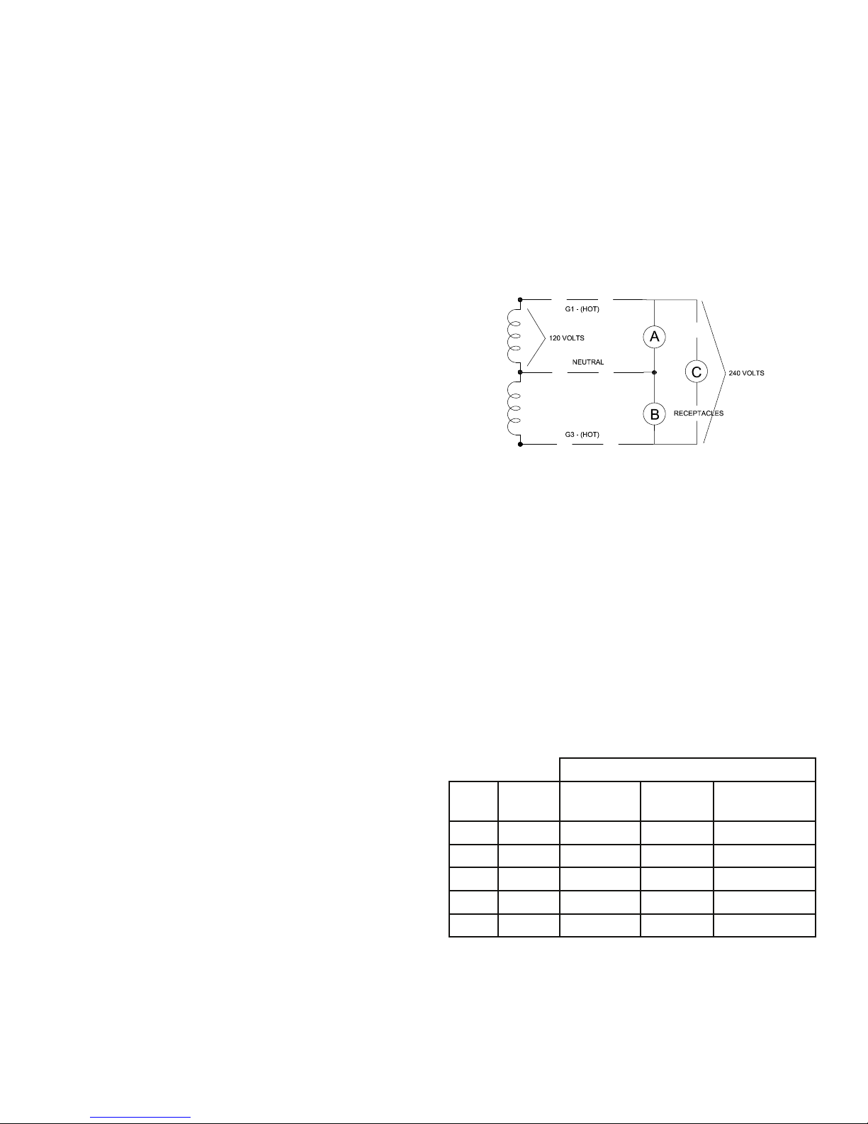
GENERATOR CONNECTIONS
W6010DE: 120 Volt and 240 Volt receptacles are provided for
connection to various loads. The following diagram represents this
5,160 watt (rated output) generator. A & B represent the 120 volt output
legs of this generator. Up to 2,580 watts at 120 volts (43 Amps) can be
drawn from the receptacles attached to either A or B output legs. This
generator is capable of producing 21.5 Amps of 240 volt current at C.
Check the appliance or tool nameplates for the current and voltage to
insure compatibility. Remember that power taken from C reduces the
power available equally at both A and B and vice versa.
STARTING ELECTRIC MOTORS
Electric motors require much more current (amps) to start them than to
run them. Some motors, particularly low cost split-phase motors, are
very hard to start and require 5 to 7 times as much starting current as
running current. Capacitor motors are easier to start and usually require
2 to 4 times as much starting current as running current. Repulsion
Induction motors are the easiest to start and require only 1 1/2 to 2 1/2
times as much starting as running current.
Most fractional horsepower motors take about the same amount
of current to run them whether they are Repulsion Induction (RI),
Capacitor (Cap), or Split-Phase (SP) type. The following chart shows
the approximate current required to start and run various types
and sizes of 120 Volt 60 cycle electric motors under average load
conditions.
STARTING AMPS
Running
HP
1/6 3.2 16 to 22 6 to 13 5 to 8
1/4 4.5 22 to 32 9 to 18 7 to 12
1/3 5.2 26 to 35 10 to 21 8 to 17
1/2 7.2 Not Made 14 to 29 11 to 18
1 13 Not Made 26 to 52 20 to 33
Amps
Split Phase
Motor
Capacitor
Motor
Repulsion
Induction Motor
The gures given in the previous chart are for an average load such
as a blower or fan. If the electric motor is connected to a hard starting
load such as an air compressor, it will require more starting current. If
it is connected to a light load, or no load such as a power saw, it will
require less starting current. The exact requirement will also vary with
the brand or design of the motor.
5REV C
OPM-107
 Loading...