

Page 1
COMPACT PTO
GENERATORS
OPERATOR INSTRUCTION MANUAL
COMPACT SERIES
TRACTOR DRIVE ALTERNATORS
W15PTOS/D
60706-179-8100
Page 2

TABLE OF CONTENTS
INTRODUCTION ...................................................................................................................................................... 1
SAFETY INFORMATION ......................................................................................................................................... 1
FOUNDATION MOUNTING ..................................................................................................................................... 2
TRAILER MOUNTING.............................................................................................................................................. 3
LOAD DISCONNECT PLUG INSTALLATION ......................................................................................................... 3
OPERATING THE ALTERNATOR........................................................................................................................... 3
MAINTENANCE REQUIREMENTS ......................................................................................................................... 4
OPERATION OF TRACTOR DRIVEN ALTERNATOR ........................................................................................... 4
PROCEDURE FOR USE ......................................................................................................................................... 6
PTO ALIGNMENT .................................................................................................................................................... 6
LUBRICATION ......................................................................................................................................................... 6
TESTING OF RECTIFIERS ..................................................................................................................................... 7
HANDLING PROCEDURES FOR RECTIFIER DIODES ........................................................................................7
TESTING STATOR .................................................................................................................................................. 7
WINDING RESISTANCES ....................................................................................................................................... 7
SERVICE DIAGNOSIS............................................................................................................................................. 8
RECEPTACLE PANEL ASSEMBLY ILLUSTRATION/WIRING DIAGRAM ............................................................ 9
COMPLETE UNIT ASSEMBLY ILLUSTRATION .................................................................................................... 10
TWO WHEEL TRANSPORT .................................................................................................................................... 11
WINCO LIMITED WARRANTY ................................................................................................................................ 12
Copy you model and serial number here.
MODEL
No other Winco generator has the same serial
number as yours. It is important that you record the
number and other vital information here. If you
SERIAL NUMBER
PURCHASE DATE
should ever need to contact us about this unit it will
help us to respond to your needs faster.
DEALER
CAUTION
FOLLOW THE INSTRUCTIONS IN THE OWNER’S MANUAL SPECIFICALLY WHEN PUTTING THIS ALTERNATOR INTO SERVICE.
IMPORTANT
ALL STANDBY POWER PLANTS INCLUDING TRACTOR DRIVEN ALTERNATORS SHOULD BE PERIODICALLY EXERCISED. FOR PROPER MAINTENANCE OF YOUR TRACTOR DRIVEN ALTERNATOR, IT
SHOULD BE OPERATED FOR ONE HOUR CARRYING RATED LOAD AT LEAST TWICE A YEAR. THIS WILL
ASSURE THAT YOUR ALTERNATOR IS IN OPERATING CONDITION AND READY FOR USE WHEN AN
EMERGENCY CONDITION DEVELOPS.
PARTS LIST, PARTS DRAWINGS, AND WIRING DIAGRAM PERTAINING TO YOUR UNIT ARE ENCLOSED
WITH THIS MANUAL.
This manual covers the latest compact portable tractor driven Power Take Off (PTO) generator set model from Winco.
This 15,000 watt generator, is designed to provide120/240V single phase electrical power for standby and utility
service when commercial power interrupted, inaccessible or impractical. This PTO unit has a cast iron gear cases with
a 1-3/8” – 6 spline, 540 rpm input shafts and brushless, heavy-duty 3600 rpm, 2 pole, low waveform distortion generators.
This compact PTO generator units is designed to provide reliable electrical power for customers who already have a
compact utility tractor with 24 to 40 horsepower and a 540 rpm PTO shaft. The PTO unit is a cost-effective way of
providing needed electrical power without the cost or added maintenance of a dedicated drive engine. Primary applications for these PTOs are for infrequent or medium duty loads where the unit will normally be operated less than 50
to100 hours per year. Typical uses might be for farm, ranch or home standby or portable field power away from
convenient utility or where running an extension cord is impractical. The compact PTO units are built to last, but are not
intended for prime power (continuous or sole source) applications.
60706-179-8100
Page i
Page 3

All PTO units have a full control panel with features like large frequency meter, mainline circuit breaker, convenience
and full load 4-wire receptacles. The full load matching plug is also included for customers load connection cord set.
Traditional Winco power, convenience and reliability are standard features of this new series of compact PTO generators.
FEATURES BY MODEL
TRACTOR INPUT GEAR MOTOR ** WATTS AMPS @
PTO HP SHAFT LUBE STARTING MAX / RATED 120/240V FEATURES*
W15PTOS/C 36/30 1-3/8 6SPL 16 OZ 8 HP 18,000 / 15,000 83 / 60 1, 2, 3, 4, 5, 6
**MOTOR STARTING – CODE ‘G’ CAPACITOR START –
*FEATURES – LISTED BELOW BY REFERENCE NUMBER WITH EXPLANATION –
1 – Brushless, low harmonic design with skewed rotor and damper windings for minimal load noise
2 – Capacitor Excitation
3 – Dual voltage - 120/240 volt output
4 – 4 wire Load connection plug for convenient full load 120/240 volt output cordset
5 – 15Amp duplex convenience receptacle
6 – Large face Frequency meter for setting proper speed
INTRODUCTION
The words generator and alternator are used interchangeably but have the same meaning.
This manual covers standby generators driven by the
power take-off of a compact tractor. This generator
use a external voltage regulator excitation system. All
generators are carefully inspected, tested and packaged for shipment at the factory. The generator should
be unpacked as early as possible upon receipt and
inspected for damage which may have occurred during
shipment. Any damage noted should be promptly
reported to the carrier in order that a claim can be filed
to recover the cost of the damage. If at all possible,
this damage should be noted on the freight bill at the
time of delivery. If the damage appears to be of a
major nature, the generator should not be operated
until the fault has been corrected.
Tractor driven generators are designed to deliver
voltage and current similar to that of the normal power
line. Equipment that can be operated on normal power
can also be operated by the generator, provided that
the capacity of the generator is not exceeded. It
should be remembered that the power line, for all
practical purposes, is backed by an unlimited generator.
When not in use the generator should be stored in a
clean dry location. All types of mechanical equipment
suffer from long periods of storage without use. The
generator should be used at frequent intervals to
prevent deterioration and detect possible fault before
an emergency condition develops.
SAFETY INFORMATION
This generator set has been designed and manufactured to allow safe, reliable performance. Poor maintenance, improper or careless use can result in potential
deadly hazards; from electrical shock, exhaust gas
asphyxiation, or fire. Please read all safety instructions
carefully before installation or use. Keep these instructions handy for future reference. Take special note
and follow all warnings on the unit labels and in the
manuals.
ANSI SAFETY DEFINITIONS
DANGER:
DANGER indicates an imminently hazardous situation
which, if not avoided, will result in death or serious
injury. This signal word is to be limited to the most
extreme situations.
WARNING:
WARNING indicates a potentially hazardous situation
which, if not avoided, could result in death or serious
injury.
CAUTION:
CAUTION indicates a potentially hazardous situation
which, if not avoided, may result in minor or moderate
injury. It may also be used to alert against unsafe
practices.
NOTE:
CAUTION is also used on the unit labels and in this
manual to indicate a situation that could result in
serious damage or destruction of the equipment and
possible personal injury.
Page 1
60706-179-8100
Page 4

GENERATOR SAFETY INFORMATION
1. ELECTRIC SHOCK - The output voltage present in
this equipment can cause a fatal electric shock. This
equipment must be operated by a responsible person.
a. Do not allow anyone to operate the generator
without proper instruction.
b. Guard against electric shock.
c. Avoid contact with live terminals or receptacles.
d. Use extreme care if operating this unit in rain or
snow.
e. Use only three-prong grounded plugs and
extension cords.
f. Be sure the unit is properly grounded to an
external ground rod driven into the earth.
g. Do not make or break electrical connection under
load.
2. FIRE HAZARD - Gasoline, diesel and other fuels
always present a hazard of possible explosion and/or fire.
a. Keep a fire extinguisher nearby and know its
proper use. Fire extinguishers rated ABC by NFPA are
appropriate.
3. DEADLY EXHAUST GAS - Exhaust fumes from any
engine contain carbon monoxide, an invisible, odorless
and deadly gas that must be mixed with fresh air.
a. Operate only in well ventilated areas.
b. Never operate indoors.
4. NOISE HAZARD - Excessive noise is not only tiring,
but continual exposure can lead to loss of hearing.
a. Use hearing protection equipment when working
around this equipment for long periods of time.
b. Keep your neighbors in mind when permanently
installing this equipment.
5. CLEANLINESS - Keep the generator and surrounding
clean.
a. Remove all grease, ice, snow or materials that
create slippery conditions around the unit.
b. Remove any rags or other material that could
create potential fire hazards.
6. SERVICING EQUIPMENT - All service, including the
installation or replacement of service parts, should be
performed only by a qualified technician.
a. Use only factory approved replacement parts.
b. Do not work on this equipment when fatigued.
c. Use extreme caution when working on electrical
components. High output voltages from this equip
ment can cause serious injury or death.
d. Always avoid hot mufflers, exhaust manifolds, and
engine parts. They all can cause severe burns in
stantly.
7. INSTALLATION - Installing an isolation power transfer
switch and PTO generator is not a typical “do-it-yourself”
project. Consult a qualified, licensed electrician or
contractor. The installation must be safe and comply with
all national, state, and local codes. See page 11.
a. Never operate the PTO drive generator without
having it properly mounted to a concrete base or
approved trailer.
b. Never connect the PTO generator to an existing
electrical system without installing an isolation
transfer switch.
c. Always insure the drive shaft is straight and level
before operating the generator.
8. OPERATION - PTO drive shafts (tumbling bars) have
many inherent dangers, extreme caution must be exercised when using them.
a. NEVER allow children around a drive shaft when it
is in operation.
b. Keep all safety guards and shields in place and
securely tightened.
c. Never operate a drive shaft that has been damaged
or had the safety shield removed.
d. Never step over a drive shaft while it is running.
e. Never wear a necktie, loose articles of clothing, or
anything else that can be caught in moving parts.
f. Never try to stop a turning drive shaft with your
hand or your foot.
INSTALLATION
FOUNDATION MOUNTING
Mount the generator on a foundation if it is to be used as
a permanent or standby power source. See “TRAILER
MOUNTING” if generator will be used as a portable power
source (Figure 1). When planning a foundation consider
the following points:
A.The foundation location should enable aligning the
drive shaft (tumbling bar) in a straight or nearly straight
line between the power take-off and the generator input
shaft. Misalignment must be less than 10 degrees during
generator operation, even though the mechanical design
of the tumbling bar would allow greater misalignment.
B.The foundation must be solid enough to absorb generator starting and reflected load torque during operation.
C.The foundation surface should be flat.
D.Space is required around the generator for mounting
switching devices, making connections, and for servicing.
E.All four generator mounting pads must rest firmly on
the foundation. Install shims if necessary to even out the
foundation under the mounting pads then bolt the generator firmly in place.
60706-179-8100
Page 2
Page 5
TRAILER MOUNTING
Mount the generator on a trailer if you plan to use it as a
portable power source. See Figure 1. When selecting or
building a trailer to mount the generator, consider the
following points:
A.The trailer construction must be strong enough to
support the generator.
B.The design of the trailer must enable the trailer to
remain stable during operation, and to resist tipping
caused by generator
starting and reflected load
torque.
WARNING: Personal
Injury & Equipment
Damage
TRAILER MAY TIP OVER
AND CAUSE INJURIES
IF WHEELS ARE NOT
SPACED FAR ENOUGH
APART.
C.The trailer height and
mounting position of the
generator on the trailer
should enable aligning the
drive shaft (tumbling bar) in a straight or nearly straight
line between the power take-off and generator input
shafts. Misalignment must be less than 10 degrees
during generator operation, even though the mechanical
design of the tumbling bar would allow greater misalignment.
D.The generator mounting area of the trailer bed should
be flat.
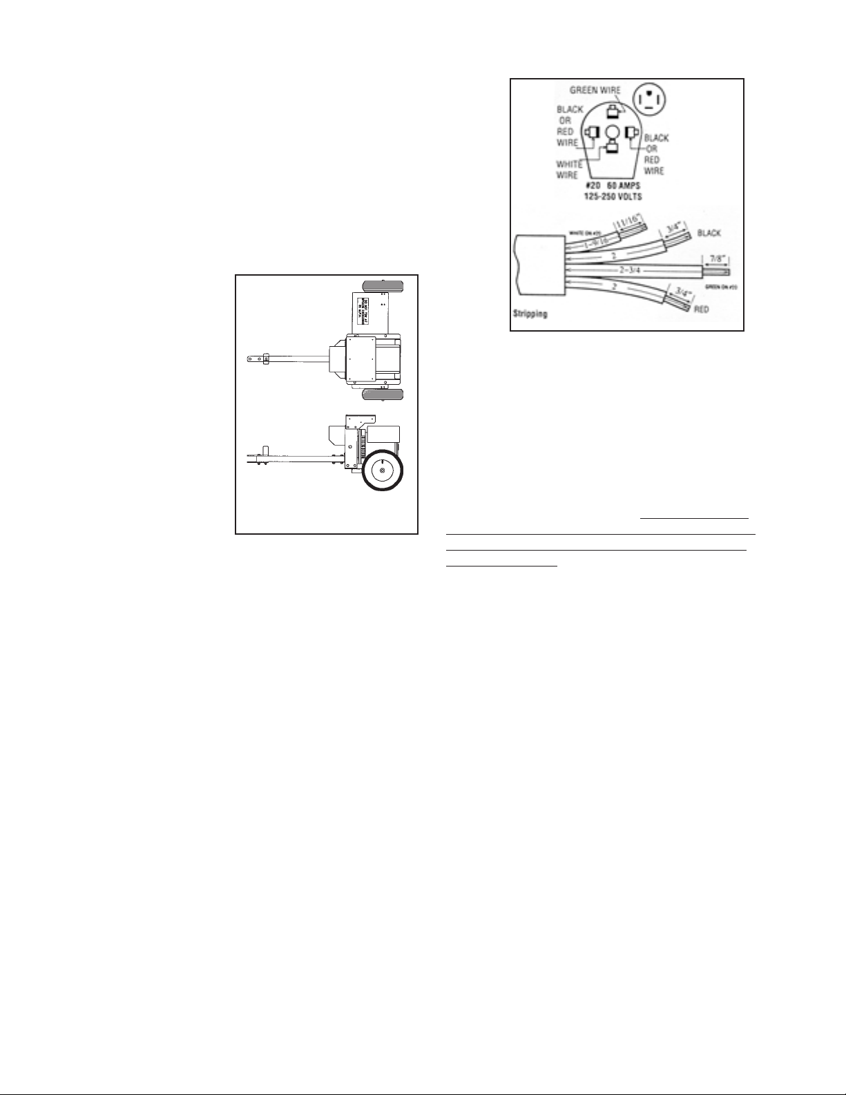
Figure 1
Figure 2
To assemble and wire the load disconnect plug, proceed
as follows:
1. Strip outer jacket 2-3/4”.
2. Cut and strip leads to lengths specified for the
particular plug.
3. Disassemble cable clamp and top cover.
4. Remove one blade at a time, insert the stripped end
of the appropriate colored wire designated above,
and tighten the set screw.
5. Fit blades through slots in bottom cover and push
down until home. Please note: Make sure blades
are in correct slots and oriented in accordance with
the diagram above or you will not be able to close
the top cover fully.
6. Place top plastic cover over assembly and partially
tighten the bakalite assembly screw. Realign
blades straight (so they fit into the top bakelite
housing properly) and tighten the assembly screw.
7. Assemble cable clamp over the outer jacket of the
wire and tighten the two clamp screws.
Special Note: For small size round (less than 3/4”) and
flat cables, the wire clamp may be inverted.
All four generator mounting pads must rest firmly on the
trailer bed. Install shims if necessary to even out the bed
under the mounting pads, then bolt the generator firmly in
place.
Assembly
The only assembly work required after unpacking the
generator is to assemble and wire the load disconnect
plug, which is packed in the generator carton.
WARNING: Personal Injury
DISCONNECT POWER BEFORE WIRING
IMPORTANT: Use copper wire only. Do not use tinned
conductors. Sizing cable - see NEC 400-5.
CORD SIZE: #4/4 conductor cord SO, 1.25 inch dia. max.
WARNING: Failure to wire as instructed may cause
personal injury or damage to device or equipment.
To be installed or checked by an electrician or
qualified person only.
OPERATING THE ALTERNATOR
WARNING: Personal Injury
When working on or around these generators, do not
wear loose fitting clothing or any articles that may
get caught in moving parts.
A properly rated and installed double throw manual
power isolation transfer switch must be used with a
standby generator. The transfer switch isolates the load
from the power line and allows you to safely operate your
loads without endangering the power line repair crew.
See page 11.
Page 3
60706-179-8100
Page 6

The load, connected to the normal terminals of the
transfer switch, is energized by the normal power line
when the switch is in the normal position. The generator,
connected to the emergency terminals of the switch,
furnishes power when the switch is in the emergency
mode position.
When the normal power fails, the generator is attached to
the tractor by means of the power take-off shaft.
WARNING: Personal Injury
Be sure the safety shields are in place and retained.
Start the tractor and adjust the speed until the Voltage
meter on the generator panel reads the proper Voltage
235 volts to 245 volts.
Check the connected load to assure that all heavy
electrical equipment is disconnected.
Move the transfer switch handle to the emergency
position connecting the load to the generator.
dry elevated surface such as a board. Do not have it
resting on a dirt surface. (Figure 3)
MAINTENANCE REQUIREMENTS
1. Maintain proper oil level in the PTO gear case. See
page 5 for list of recommended vendors. Do not overfill,
maintain level to the center of clear site gauge, approximately four (4) inches from the
bottom of the gear case on the
right side (Figure 4).
CAUTION: Equipment
Damage
Do not overfill generator
gear case. Overfilling
causes overheating and oil
seal failure.
2. Inspect for loose or
broken wiring connections. Make sure that wiring connections are not loose at the generator end, circuit
breakers, and receptacles.
Switch on all required electrical equipment within rated
capacity of the generator, then readjust tractor speed to
maintain the proper frequency.
NOTE: Equipment Damage
If the load includes motors turn them on one at a time,
highest starting current motor first, next highest second,
etc.
If the circuit breaker of the generator control panel trips
during operation, the connected load is greater than the
rated generator capacity.
Reduce the load by disconnecting any nonessential
equipment during emergency conditions and reset the
breaker to resume power feed.
When the normal commercial power is restored, for at
least 15 minutes without interruption, the transfer switch
can be returned to the normal position and the tractor
drive generator shut down. Reduce speed gradually to
minimize stress in drive line.
If the generator is mounted on an offhighway trailer, such as the Winco
trailer, it should be stored in a garage,
barn or machine shed in a dry and
clean location. The generator should
be covered with a tarpaulin to prevent
the entrance of dust, chaff, and/or
moisture.
The generator may be stored on end,
provided the generator is on a clean,
3. Do not allow dirt or chaff to collect in the interior of the
generator or the ventilation openings. Inspect for indication of the entrance of mice or insects into the generator.
The inlet and outlet openings are louvered, but possible
damage to the louvers could occur. Mice can destroy the
generator winding.
WARNING: Equipment Damage
DO NOT CLEAN THE GENERATOR WHILE IT IS
RUNNING.
CAUTION: Equipment Damage
Most electrical equipment in North America operates
satisfactorily at frequencies between 59 and 61 Hz
(cycles per second). Operating the generator at
frequencies outside that range may cause damage to
the generator and/or to electrical equipment driven by
the generator.
OPERATION OF
TRACTOR DRIVEN ALTERNATORS
When the alternator is not in use, it must be maintained in
a clean and dry condition. The inside of the panel, frame
and air inlet and outlet must be free from dirt, chaff, and
moisture (including condensation).
When connection is made at the meter pole, a double
throw manual isolation power transfer switch must be
used. Normal power is connected to the top, the load at
the center, and the alternator at the bottom of the switch.
Warranty is void if an isolation transfer switch is not
used (check instruction manual on transfer switch.)
60706-179-8100
Page 4
Page 7

ELECTRICAL CONNECTIONS
CAUTION:
Only qualified electricians should install electrical
wiring. Wiring must conform to all applicable national, state, and local codes. (Reference: National
Fire Protection Association Manual No. 70, National
Electrical Code.)
DANGER: PERSONAL INJURY
IF THE GENERATOR IS TO BE USED AS A
STANDBY POWER SOURCE, A SPECIAL DISCONNECT SWITCH MUST BE INSTALLED TO SEPARATE THE GENERATOR AND THE COMMERCIAL
POWER LINES. THE DISCONNECT MUST ISOLATE THE GENERATOR FROM THE COMMERCIAL
POWER LINES AND THE LOAD WHEN THE GENERATOR IS ON STANDBY, AND MUST ISOLATE
THE COMMERCIAL POWER LINES FROM THE
LOAD AND THE GENERATOR WHEN THE GENERATOR IS SUPPLYING POWER. SEE FIGURE 6
Page 5
Figure 6
60706-179-8100
Page 8

PROCEDURE FOR USE
1. Set the manual transfer to mid or normal (up)
position.
2. Connect the power take-off shaft securely to the
alternator and the tractor. Position as near to a straight
line as possible.
3. Slowly adjust power take-off up to maintain the
the proper voltage reading on the meter (235 to 245
volts).
4. Plug 4 wire load cord set into receptacle. Place
transfer switch in the emergency position.
5. Place the load circuit breaker in the “on” position. If
the breaker trips, move manual transfer switch to“off” or
normal position. Check for short circuit or grounded
connection in the load cable to the double throw switch
and repair. A breaker that trips from overload or short
circuit must be reset by moving to “off” before reclosing.
DANGER: Personal Injury
TRACTOR MUST BE SHUT OFF AND THE POWER TAKE-OFF MUST BE DISENGAGED AT THIS TIME.
6. Keep meter at the proper voltage by adjusting tractor
speed.
7. The return of normal power will be indicated by the
lamp on the front of transfer switch; (applicable only when
the transfer switch is equipped with indicating lamps or
your electrician has installed them). After sufficient time to
assure that power restoration isn’t temporary, return the
transfer switch to normal power (10 - 20 minutes).
8. Place the alternator circuit breaker in “off” position.
Do not remove plug before opening the breaker.
9. Slowly reduce power take-off speed to a minimum
and disengage the power take-off. Some tractors have a
brake on the power take-off that stops the shaft instantly.
Stopping the alternator rotor instantly from rated speed
may result in a broken shaft or other drive line failures.
10. Exercise PTO alternator for one hour under load at
least twice a year.
PTO ALIGNMENT
Synchronized
Unsynchronized
Figure 5
Position the alternator in such a manner that the power
take-off shaft is as near to direct line in all directions as
possible. This will increase the life of the power take-off
shaft, reduce light flicker, reduce wear on bearings of
both the power take-off and the alternator, and reduce
vibration. The maximum angle from a straight line should
not exceed 10°. For a power take-off shaft length of 42
inches, 10° is approximately 7 inch misalignment. For
extended distance the maximum misalignment would
increase 2 inches for each foot. For example: For a 4
foot PTO shaft, the maximum misalignment is 8 inches
from a straight line.
LUBRICATION
1. Check the generator gear case oil level before each
use of the generator. See Figure 4. Maintain the oil level
before each use of the generator. Maintain the oil level at
oil level plug height. The generator is shipped with
lubricant in the gear case.
Specifications for gear case lubricant are: API Service:
GL-5 EP Rated, Grade: SAE 85W-90-140, Amount: 1
pint
The following kinds of oil are recommended for use in the
generator gear case:
Mobil SAE 85W90-140 API Service GL-5
Sunoco/DX XL80W90-140
Kendal Three Star 85W-140
Amoco 85W140 or equivalent
NOTE: Do not over lubricate
the universal joints.
60706-179-8100
2. The generator bearings are factory lubricated and
sealed, and require no further lubrication.
3. The splined generator input shaft should be cleaned
and lubricated with a thin film of grease before and after
each use of the generator. See Figure 6 for lubrication
schedule.
4. The drive shaft (tumbling bar) requires greasing.
Keep the universal joints in the coupling shaft free from
grease and dirt buildup. See Figure 6 for lubrication
schedule.
Figure 6
Page 6
Page 9

NOTE: THE FOLLOWING INFORMATION IS FOR REFERENCE ONLY - CONSULT A
QUALIFIED SERVICE PERSON FOR FURTHER TESTING AND REPAIR.
Testing of Rectifiers
Unbolt the rectifier diode stud from the mounting clamp.
Move rectifier away from the metal stud.
1. Connect black lead of meter to stud of rectifier
and red lead to the solder terminal. Meter should
read a low resistance.
bending occurs closer than 1/8 inch to the rectifier body,
and that header seals are not fractured or broken. If this
seal is broken, it removes mechanical support for the lead
and allows entry of moisture into the rectifier, almost
assuring early failure.
2. Now, reverse the lead on rectifier terminals.
Meter should read open circuit of infinite resis
tance. A shorted diode will give low resistance
reading in both directions. An open diode will give a high
resistance (infinite) reading in both directions.
Handling Procedures for Rectifier Diodes
1. Rectifier diodes should be handled in a manner which
avoids the possibility of sudden shocks being applied,
such as those encountered in dropping from a work
bench to a hard floor. Damage done to the rectifier by
such shocks may not be detected by subsequent testing,
yet may cause poor system reliability.
2. Any lead trimming or forming operations should be
done with care to avoid damaging the leads or the glass
header seals.
3. Leads should never be bent or twisted. If lead forming
is necessary the lead should be supported so that no
Testing Stator
1. Instrument required - Volt-Ohmmeter. Set on Ohm
X1 scale.
2. Check Ohmmeter by touching leads together.
Reading should be zero.
3. Tag and lift control wires from stator winding(s) to be
checked.
4. First, check if stator winding(s) are grounded
a. Connect one lead of Ohmmeter to ground.
b. Touch other lead to each stator wire. Meter
should stay at infinite (not move).
c. If reading is indicated, stator is grounded and
should be replaced.
d. Check all three windings.
4. Care must be taken during all soldering operations. It
is unsafe to exceed the general specification to which
diodes are tested for solder ability. This is 10 +/- 2
seconds at a temperature of 230°C + 5°C at a point 1/16
+/- 1/32 inch from the diode body. This is not as restrictive as it may sound, since 230°C is 446°F and 60/40
solder melts at 375°F, and with proper procedure and
soldering tools a solder joint can be made in 4 to 7
seconds. Also, solder joints are almost never made this
close to the diode body. Heat sinks, such as a pair of
needle nose pliers or alligator clips, can be attached to
the lead between the solder joint and the diode body to
further reduce the possibility of heat damage.
Also, precautions should be taken to prevent solder or
flux bridging which causes a conductive path across the
case of the rectifiers. As a precaution all flux should be
removed by using alcohol and a small brush. Pay
particular attention to assure that glass header seals are
free of all flux.
Stator - 6 Wires - 3 Windings 1 Phase
This armature has two power windings and one excitation
(auxiliary) winding.
1. Connect ohmmeter one lead to T1-red. Other lead to
T2-green. Meter should read near zero. Then other lead
to T3-black. Meter should read infinite. Then other lead to
Z1-white. Meter should read infinite.
2. Connect one lead to T3-black. Other lead to T4-yellow
Meter should read near zero. Then other lead to Z1-white.
Meter should read infinite.
3. Connect one lead to Z1-white. Other lead to Z2-brown
Meter should read near zero
5. Second, check stator windings for opens.
Symptom: when generator was running, no voltage
on one line to neutral.
TRACTOR DRIVE WINDING RESISTANCES
ROTATING FIELD TRACTOR DRIVE
ROTOR STATOR CAPACITOR
MAIN POWER POWER AUX. 450 VAC
MODEL T1-T2 T3-T4 Z1-Z2
W15PTOS/C 3.124 0.0893 0.0893 0.503 101.5 MFD
Page 7
60706-179-8100
Page 10

SERVICE DIAGNOSIS
POSSIBLE CAUSE
REMEDY
LOW OUTPUT VOLTAGE
Low Speed
1. Undersized/overloaded.
2. Defective governor.
3. Low power - worn engine.
High line loss. Indicated by lower voltage at load than at
generator terminals.
Defective voltage regulator.
Shorted or grounded rotor coil.
Defective stator
Check for overload on the tractor or undersized.
Check tractor governor. Tight or defective throttle levers
and joints.
Worn or defective tractor engine
check list.)
Increase size of line wiring. Might also be the result of loose
connection indicated by excessive heating at the loose
connection terminal.
Replace as required
Test and replace if defective.
Repair or replace as required
(see engine manufacturers
HIGH OUTPUT VOLTAGE
Generator is spinning to fast, slow tractor down.
Readjust or Replace as required
EXCESSIVE HEATING
Clogged ventilating inlet and/or outlet. Clean screens, make sure interior of generator is unobstructed.
NO OUTPUT VOLTAGE
Broken or corroded connection. Clean and tighten generator and receptacle connections.
Defective diode(s) on rotor. Replace defective diode(s).
Open excitor circuit in stator Repair or replace statorassembly.
Grounded or shorted rotor winding. Replace grounded rotor assembly.
Loss of residual magnetism. Usually occurs only after
disassembly of field frame or severe mechanical stress/abuse.
Shorted stator winding. This can be identified by the use of an
internal “growler” at a competent rewinding shop.
Grounded stator. Check winding by test lamp or high potential
tester from stator leads to lamination.
Open stator circuit. Measure circuit between leads with an
ohmmeter. Should have a circuit between any pair of leads.
Defective Capacitors
Back flash the 120 volt circuit with 12 volts DC
Replace stator. (Include generator model and serial number
on the order.)
Same as above.
Same as above.
Test and replace if defective.
VOLTAGE UNSTEADY/ LIGHTS FLICKERING
PTO drive line alignment.
Drive line knuckles out of sync. (See Figure 5.)
Realign within 10 degrees.
Resync drive line halves.
60706-179-8100
Page 8
Page 11

RECEPTACLE
PANEL
REF# PART NUMBER QTY DESCRIPTION
01 300079-3 1 Control Box, Bottom, Front, Back
02 91370-000 1 Voltmeter
03 99280-001 3” Grommet
04 62487-003 22” Loom
05 300136 1 Receptacle NEMA 14-60R
06 94378-000 1 Neutral Stand Off
07 63708-000 1 Ground Lug
08 50766-000 1 Duplex Receptacle NEMA 5-20
09 91286-001 1 Circuit Breaker 20 Amp/120 Volt
10 57030-005 1 Circuit Breaker 60 Amp/240 Volt
NI 300080-1 1 Control Box Cover
NI 300137 1 Plug (NEMA 14-60P) Shipped Loose
WIRING DIAGRAM
Page 9
60706-179-8100
Page 12

COMPLETE UNIT ASSEMBLY
REF PART # QTY DESCRIPTION
1 91370-000 1 Voltmeter
2 300080-1 1 Control Box
Cover
3 Z-2568 1 Decal
4 Z-9941 1 Decal
5 Z-2553 1 Decal
6 300074-6 1 Right Side Frame
7 300077-5 2 Rear Frame
8 Z-2516 1 Decal
9 15209-000 1 Decal
10 300074-5 1 Left Side Frame
11 300079-3 1 Control Panel
Bottom
60706-179-8100
REF PART # QTY DESCRIPTION
12 99839-001 1 Generator,
Mecc Alte Spa
Model S20F-230/A
13 300086-1 1 Drive Shaft Guard
14 63966-407 1 Name Plate Kit
15 98478-000 1 Winco Decal
16 99841-001 1 Gear Case Support
NI 300323-112 1 Capacitor,
31.5 mf, 425 V
NI 300323-212 2 Capacitor,
35 mf, 450 V
NI 300153 1 Gear Case
NI Not Illustrated
Page 10
Page 13

TWO WHEEL TRANSPORT
DESCRIPTION PART NO.
1 SUPPORT, TONGUE (QTY. 2) 300081
2 HITCH, TONGUE (QTY. 2) 300082
3 TONGUE 300083
4 AXLE (QTY. 2) 300085
5 SUPPORT, AXLE 300164
6 SUPPORT, PTO SHAFT 300161-1
7 SUPPORT, PTO SHAFT 300161-2
8 TIRE/RIM, PNEUMATIC (QTY. 2) 43657-000
Page 11
60706-179-8100
Page 14

ONE YEAR P.T.O. DRIVEN ALTERNATOR
LIMITED WARRANTY
Winco Inc. hereinafter referred to as Winco, warrants for a period of one year to
the original user that each Winco PTO driven alternator is free from defects in
material and factory workmanship if properly installed, serviced and operated
under normal conditions according to Winco’s published instructions.
Manufacturer’s obligation under this warranty is limited to correcting without any
labor or material charge to the user for the first year at its factory, or at its authorized repair centers, any part or parts which shall be returned and which upon
examination shall disclose to Winco’s satisfaction to have been originally defective
in material or in workmanship.
All transportation charges on parts or units submitted for replacement or repair to
the factory or authorized repair centers under this warranty must be borne by the
purchaser.
This warranty does not apply to items which are subject to normal wear or any part
or parts which have been subject to misuse, negligence, accident or which have
been repaired or altered by other than persons authorized by Winco.
Winco shall not be liable for loss, damage or expense directly or indirectly from the
use of its product nor for the fitness of product for any specific application or
particular purpose.
Winco shall not be liable for any incidental and consequential damage.
There is no other express warranty. Winco hereby disclaims any and all implied
warranties, including but not limited to those of merchantability and fitness for a
particular purpose to the extent permitted by law.
This warranty is effective for all compact PTO driven alternators manufactured
after August 15, 1998.
If this alternator is used for standby service, this warranty is void unless a multipole, double throw switch is installed between the alternator and the service
entrance switch. Do not operate PTO alternator without the shield installed.
225 SOUTH CORDOVA, LE CENTER, MN 56057
PHONE: 507-357-6831 FAX: 507-357-4857
60706-179-8100
Page 15

225 SOUTH CORDOVA AVE
LE CENTER MN 56057
1-507-357-6831
60706-179-8100
Page 16

60706-179-8100
 Loading...