

Page 1
OWNER’S OPERATING &
MAINTENANCE MANUAL
PLEASE DO NOT DISCARD THIS MANUAL! KEEP FOR FUTURE REFERENCE AND TRAINING
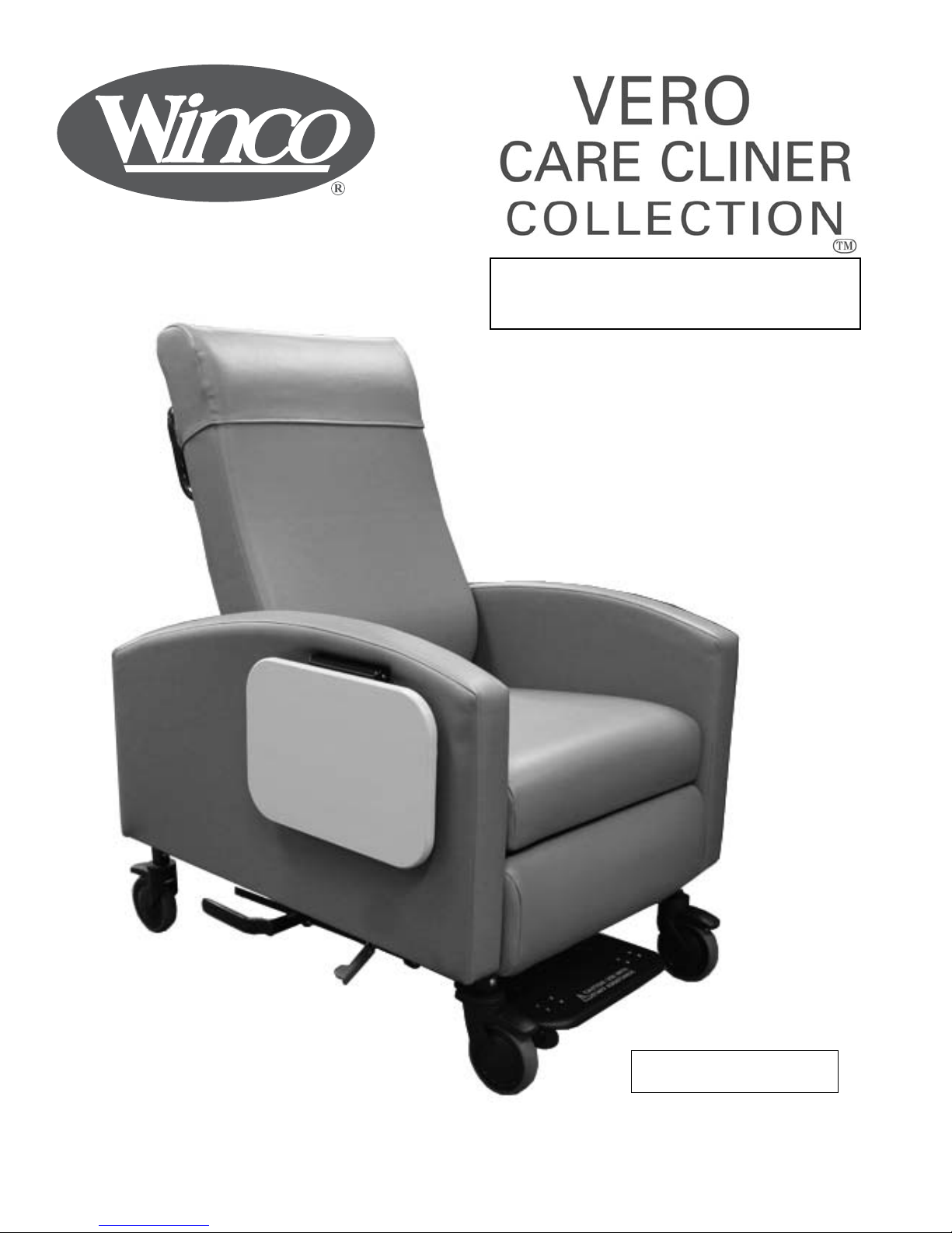
Model 6Y48-39-00-00-00-D6
Shown
Page 2

TABLE OF CONTENTS
TABLE OF CONTENTS................................................................................................................2
INTENDED USE STATEMENT......................................................................................................3
TRANSPORTATION, STORAGE, HANDLING AND DISPOSAL INSTRUCTIONS....................3
IMPORTANT SAFETY INFORMATION........................................................................................ 3-6
ASSEMBLY INSTRUCTIONS......................................................….............................................. 7-8
ATTENDANT OPERATING INSTRUCTIONS............................................................…............... 9-14
OCCUPANT OPERATING INSTRUCTIONS...............................................................................15-16
GENERAL MAINTENANCE...............................................……..................................................17
SPECIFICATIONS........................................................................................................................18
VERO CARE CLINER OPTIONS.................................................................................................19-20
CONTACT & WARRANTY INFORMATION..........................................................…....BACK COVER
2
Copyright 2016, WINCO MFG., LLC
Page 3
INTENDED USE STATEMENT
Intended Use: Vero is a recliner for use in medical settings. It is designed to provide comfort for patients seated up
to 8 hours at a time while receiving treatments such as Dialysis, Infusion or recovery from surgical procedures where
positional adjustments are beneficial. The recliner is also suitable for general use in many medical settings such as,
but not limited to hospital room chair, waiting room chair, convalescent home chair, etc.
TRANSPORTATION, STORAGE, HANDLING AND DISPOSAL INSTRUCTIONS
The product should be transported in factory packaging, inside an appropriate medium for the destination, i.e., air/sea cargo con-
tainers. The product should be stored in an environment that will inhibit rust/mold formation. Winco also recommends not leaving
the product in the factory packing in excess of 3 months. The product should always be handled in a manner consistent with the
user instructions, and in a manner to prevent contamination after each use. The product has many recyclable components and to
the extent practical, all effort should be used to recycle responsibly. Otherwise the product components shall be disposed of in
accordance with local statues.
Winco assumes no responsibility for damage or injury caused by the improper assembly,
installation, use or maintenance of this product.
IMPORTANT!
PLEASE READ THIS ENTIRE MANUAL BEFORE USING RECLINER. DO NOT INSTALL, MAINTAIN OR OPERATE
THIS EQUIPMENT WITHOUT READING AND FOLLOWING THIS MANUAL. OTHERWISE, SERIOUS INJURY AND/
OR DAMAGE TO PRODUCT MAY OCCUR.
THE INFORMATION CONTAINED IN THIS MANUAL IS SUBJECT TO CHANGE WITHOUT NOTICE. PHOTOS ARE
REPRESENTATIVE OF THE PRODUCT AND MAY VARY SLIGHTLY FROM ACTUAL PRODUCTION MODELS.
SAVE THESE INSTRUCTIONS FOR FUTURE REFERENCE!
NO PART OF THIS MANUAL MAY BE DUPLICATED IN ANY FORM WITHOUT THE PRIOR WRITTEN CONSENT OF
WINCO MFG, LLC. UNAUTHORIZED DUPLICATION MAY RESULT IN CIVIL PROSECUTION TO THE MAXIMUM
EXTENT ALLOWED BY LAW.
Products with the following markings are intended for commercial use only.
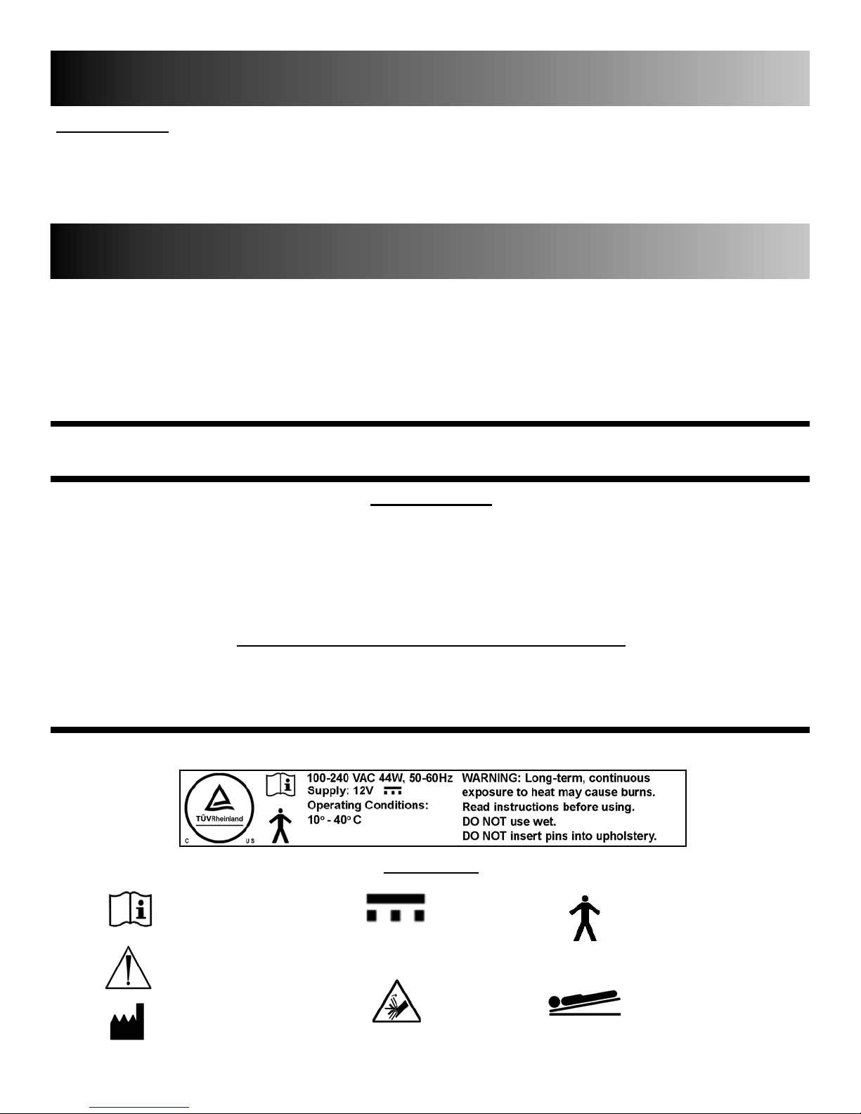
SYMBOLS
GENERAL WARNING SIGN
SYMBOL FOR MANUFACTURER
3
PINCH POINT
WARNING SIGN
TYPE B APPLIED PARTFOLLOW INSTRUCTIONS DC VOLTAGE
TRENDELENBURG
Copyright 2016, WINCO MFG., LLC
Page 4

IMPORTANT - PLEASE READ
FOR PRODUCTS WITH POWERED OPTIONS (Heat, Massage, etc...)
IMPORTANT SAFETY INSTRUCTIONS - SAVE THESE INSTRUCTIONS
(Read all instructions before using this product.)
When using an electrical appliance, basic precautions should always be followed, including the following:
DANGER - To reduce the risk of electric shock always unplug this product from the electrical outlet before cleaning,
maintenance or servicing.
WARNING:
1. Unplug this product from the electrical outlet when not in use.
2. Supervision should be provided when using this product.
3. Use this product only for its intended use as described in this manual. See page 3 for intended use.
4. Do not use attachments not recommended by the manufacturer.
5. Never operate this product if it has a damaged cord or plug, if it is not working properly, if it has been dropped or
damaged, or dropped into water, contact an authorized Winco Representative for instructions.
6. DO NOT carry or pull this product by power supply cord or use the cord as a handle.
7. Keep the cord away from heated surfaces.
8. Do not use outdoors.
9. To disconnect, turn all controls to the "off " position, then remove plug from outlet. Pull plug only to remove cord.
10. Clean switch with a damp cloth only – Warranty will be VOID if liquid is introduced into switch mechanism.
11. Extension cords are not recommended.
12. DO NOT roll recliner or other equipment over cord.
13. This product is for use on a nominal 120-volt circuit and has a three-pin plug. If the plug does not fi t into the outlet,
contact a certifi ed electrician to install the proper outlet. DO NOT MODIFY THE PLUG OR USE AN ADAPTER
WITH THIS PRODUCT.
14. For an added level of safety; Winco recommends the use of a 120 volt GFCI (ground fault circuit interrupter) outlet.
DANGER:
i. Never insert pins, or attach other metallic fasteners into/onto any part of this chair.
ii. Do not use this product if the covering shows signs of deterioration, such as checking, blistering, or cracking.
iii. KEEP DRY - Do not operate in a wet or moist condition or environment.
WARNING:
i. Long term, continuous exposure to heat may cause burns. It is recommended that skin in contact with heated
area be checked for redness and blistering during long term usage. Do not use on an infant, invalid or incapacitated person. Do not use on insensitive skin or on a person with poor blood circulation. If you are uncertain if you
should use this product, please consult your physician about the use of heat and massage.
ii. Do Not Crush/Pinch heating elements or wiring.
4
Copyright 2016, WINCO MFG., LLC
Page 5
IMPORTANT - PLEASE READ
For Heat & Heat and Massage Chairs
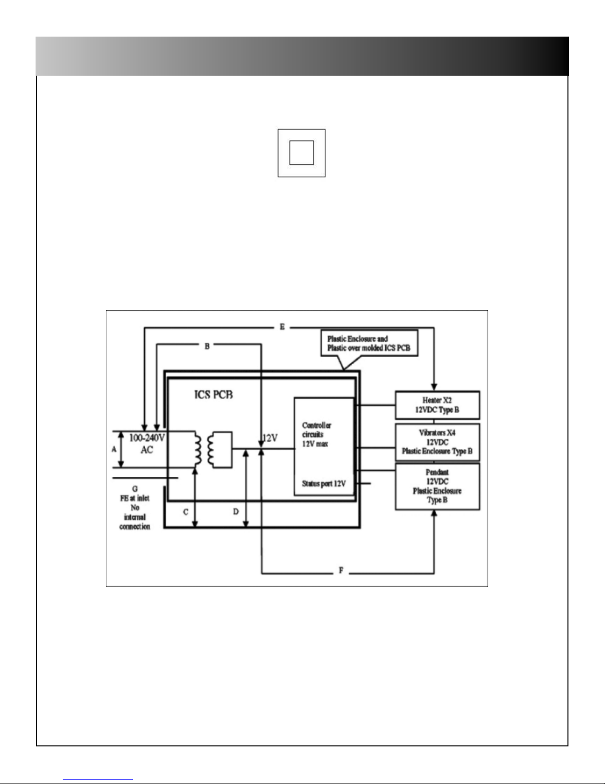
This equipment is marked with the industry recognized symbol
indicating it is a “Class II Double-Insulated” device as defi ned by IEC 60601-1. As such, it does NOT require a three conductor power cord (i.e. one
with a ground connection) for safety purposes. While the equipment can be safely operated with no ground connection, a three conductor power
cord is provided to satisfy customer expectations for typical equipment confi guration. Devices qualifying as double insulated require different testing
& examination procedures than “Class I Grounded” devices. If your facility requires the product to be tested, be sure to follow testing & examination
procedures for “Class II Double-Insulated” devices.
ISOLATION DIAGRAM FOR HEAT & MASSAGE SYSTEM
A Basic Operational
G Inlet FE pin only connects to inlet & pad
5
Area Insulation Type
B Double Insulated/Reinforced
C Double Insulated/Reinforced
D Double Insulated/Reinforced
E Double Insulated/Reinforced
F Double Insulated/Reinforced
Copyright 2016, WINCO MFG., LLC
Page 6
IMPORTANT - PLEASE READ
BASIC SAFETY PRECAUTIONS:
1. READ AND FOLLOW ALL DIRECTIONS.
2. CAUTION: Use slide-out foot support with staff assistance only.
3. DO NOT put hands, feet, or clothing into any openings when changing positions on recliner. Attendant MUST confirm that the occupants arms, legs, hands and feet are clear while changing recliner positions or SERIOUS INJURY
MAY OCCUR.
4. Remove or move chair accessories out of the way of patients legs (ie. over-lap table & pivot table) when reclining/
changing position of patient.
5. LOCK casters at all times when chair is stationary. UNLOCK casters when moving/transporting chair.
6. STAY CLEAR of the recliner mechanisms when operating chair. Keep children away from extended foot support (or
other similiar parts).
7. DO NOT use the recliner if the Trendelenburg Damper/Gas Spring is removed or damaged.
8. DO NOT use recliner for transporting in or with ANY type of vehicle or trailer. Winco recliners have not been tested
or approved for use by an occupant in any type of vehicle or trailer.
9. NEVER use the chair arms or backrest as a seat; SERIOUS INJURY OR DAMAGE MAY OCCUR.
10. Periodically check the tightness of all nuts, bolts and screws.
11. Immediately REMOVE FROM SERVICE any recliner with broken recline mechanisms, missing parts, torn upholstery, and/or other mechanical or visible damage.
12. Transport user with chair arms in the open position only in emergency situations when needed to get chair through
narrow exit doors.
13. USE ONLY WINCO AUTHORIZED REPLACEMENT PARTS.
14. NEVER EXCEED the recommended weight capacity.
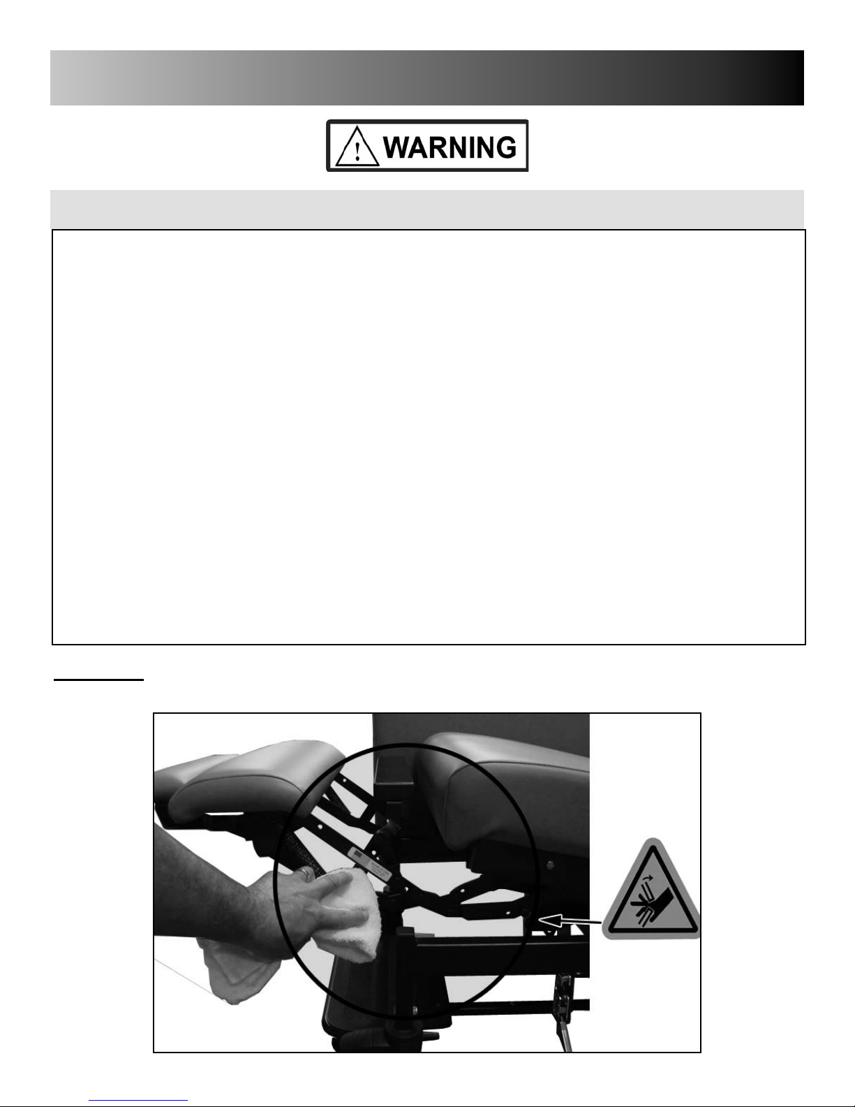
WARNING: USE CAUTION WHEN CLEANING NEAR MECHANISMS. KEEP FINGERS AWAY
FROM PINCH POINTS.
6
Copyright 2016, WINCO MFG., LLC
Page 7

ASSEMBLY INSTRUCTIONS
PREPARATION:
1. Carefully examine your product for any damage. Inspect all components.
IF DAMAGE IS EVIDENT, REFUSE SHIPMENT, & CONTACT FREIGHT CARRIER OR WINCO IMMEDIATELY.
2. Remove all packaging material that was used for shipping.
3. Carefully remove the carton from the product.
4. Save all boxes and packaging material until after you have assembled your product and have verified that all com-
ponents are functioning properly. These material are required if it becomes necessary to return the product.
BACK ASSEMBLY INSTRUCTIONS:
1. Lock ALL (4) casters on chair base. (See Lock/Unlock
Casters pg.8)
IMPORTANT:
• Keep objects and persons clear of the chair before per-
forming step 2.
2. Recline mechanism should be in the upright position.
Remove any packaging that may be on the mechanism that
might prevent installation of back.
1
2
3. Hold the rear cover, on the lower rear of the back, up
exposing the mounting brackets (A). Lift the upholstered
back by its sides while aligning the mounting brackets with
the recline mechanism (B).
WARNING:
• Keep hands clear of connection points or injury may
occur
IMPORTANT:
• Winco recommends two people be used for step 4
• Be careful not to tear or puncture vinyl.
7
3
REAR VIEW OF CHAIR
Copyright 2016, WINCO MFG., LLC
Page 8

ASSEMBLY INSTRUCTIONS
BACK ASSEMBLY INSTRUCTIONS:
5. Slide the back onto the recline mechanism until the middle hole of
the mounting bracket (A) is aligned with the middle hole of the recline
mechanism (B).
6. Install knobs (tethered to back) and fully tighten to a secure fit.
IMPORTANT:
• Test to ensure the back has been properly installed by pulling up on
the back. The back should remain securely in place.
5
6
8
Copyright 2016, WINCO MFG., LLC
Page 9

ATTENDANT OPERATING INSTRUCTIONS
2
CASTER OPERATION: Lock/Unlock
This chair offers multiple types of casters: rigid and total-lock (5" black
nylon), wheel-lock (3" black nylon) and pedestal feet.
Rigid and Total-Lock:
• The front two casters are rigid casters. They are NOT designed to
swivel in order to facilitate stable straight-line steering. The front
caster locking tabs are always accessible. When locking tab is
engaged, caster wheel will NOT roll. The rear two casters are totallock casters. They are designed to swivel 360°. When locking tab is
engaged, caster wheels will NOT roll and caster will NOT swivel.
1. TO LOCK CASTER: Press down on the wheel tab (A). Tab will lock
into position shown.
2. TO UNLOCK CASTER: Press down on the TOP of the wheel tab (B).
Tab will return to position shown.
Total-Lock:
• Total-Lock casters lock the wheel and swivel mechanism when
pressing down on the tab.
1
2
WARNING: LOCK CASTERS AT ALL TIMES,
EXCEPT WHEN MOVING/TRANSPORTING CHAIR
Wheel-Lock casters (3" Black casters only):
• Wheel-Lock casters (3" Black casters only) will lock wheel but
does NOT prevent wheel from swiveling.
1. TO LOCK CASTER: Press down on the wheel tab (A). Tab will lock
into position shown.
2. TO UNLOCK CASTER: Press down on the TOP of the wheel tab (B).
Tab will return to position shown.
Note: All 3" Black casters are wheel locking ONLY.
TOTAL and DIRECTIONAL lock features are not available.
WARNING: ALWAYS LOCK THE CASTERS WHEN THE OCCU-
PANT ENTERS OR EXITS THE CHAIR! UNLOCK CASTERS
WHEN TRANSPORTING CHAIR!!
Pedestal Feet:
• Pedestal feet are designed for chairs that are intended to remain in a
stationary position.
Note: The Foot Plate option is not available with Pedestal Feet
or 3" Black Casters.
1 2
B
A
9
Copyright 2016, WINCO MFG., LLC
Page 10

ATTENDANT OPERATING INSTRUCTIONS
RECLINE CHAIR FROM ATTENDANT POSITION:
Attendant should be positioned on the RIGHT or LEFT side of chair
CHAIRS WITH MANUAL ADJUSTMENT
1. While occupant is seated in the chair, place one hand on the arm for
support and push back on the back to recline.
CHAIRS WITH INFINITE GAS SPRING ADJUSTMENT OPTION
(These models have the recline lever (A))
1. To operate the infinite back positioning use one hand to operate the
recline lever (A) and the other hand to push on the upholstered back
(B) until desired position or maximum recline has been reached.
Release recline lever (A) to maintain desired position.
IMPORTANT:
• Do NOT force the back of the chair up or down without operating
the recline lever, or damage to the chair may occur.
1
2
A
RETURN CHAIR UPRIGHT FROM ATTENDANT POSITION:
Attendant should be positioned on the RIGHT or LEFT side of chair
CHAIRS WITH MANUAL ADJUSTMENT
1. Pull up on the back to to return to upright position.
2. Attendant can use one hand to push down on the legrest (C) until
it returns to its stored position. (Warning - Keep hands clear of
mechanism to avoid injury)
CHAIRS WITH INFINITE GAS SPRING ADJUSTMENT OPTION
(These models have the recline lever (A))
1. While occupant is reclined in the chair, attendant should use one
hand to operate the recline lever (A), while using the other hand to
pull up on back (B).
2. Attendant can use one hand to push down on the legrest (C) until it
returns to its stored position.(Warning - Keep hands clear of mech-
anism to avoid injury)
Release the recline lever (A) once the back has fully returned to the
upright position.
NOTE: The recline lever is NOT required to return legrest to its
stored position.
WARNING:
• Attendant should NOT use their foot to return the legrest to it's
stored position. Damage to mechanism may occur.
1
A
2
10
Copyright 2016, WINCO MFG., LLC
Page 11

ATTENDANT OPERATING INSTRUCTIONS
PLACING CHAIR INTO TRENDELENBURG: (Attendant ONLY) (OPTIONAL FEATURE)
Attendant should be positioned on the RIGHT or LEFT side of chair
1. While occupant is in the chair, place the chair into the fully reclined position. (SEE "Recline Chair From Attendant Position" pg.9)
2. Once chair is fully reclined, attendant can push down on the rear of
Trendelenburg lever (A) with their foot, allowing it to move down.
3. Hold Trendelenburg lever in position & push down on the chair's back (B).
This will bring the occupant into the Trendelenburg position.
Release the Trendelenburg lever.
NOTE: The chair does not lock in the Trendelenburg position.
213
IMPORTANT:
• Chair must be in the fully reclined position BEFORE occupant can be
placed into Trendelenburg.
FROM TRENDELENBURG TO RECLINE: (Attendant ONLY)
Attendant should be positioned on the RIGHT or LEFT side of chair
1. To return chair to the recline position, push down on seat (recommended) or lift up on chair back.
NOTE: Pushing down on the seat or legrest (B) is recommended for
maximum leverage.
1
11
Copyright 2016, WINCO MFG., LLC
Page 12

ATTENDANT OPERATING INSTRUCTIONS
SWING-ARM OPERATION: (Attendant ONLY) (OPTIONAL FEATURE)
Attendant should be positioned on the RIGHT or LEFT side of chair
1. TO OPEN: Press down on red latch handle to unlock Swing-Arm.
WARNING:
• Do NOT leave occupant unattended with either or both swingarms unlatched.
• Do NOT transport chair with swing-arms unlatched unless it is an
Emergency situation.
2. TO CLOSE: Push Swing-Arm fi rmly against frame.
Latch will automatically engage with an audible "click".
WARNING:
• Make sure swing-arm latches are properly engaged when swingarms are in the closed (latched) position.
Test by pulling on arms. The arms should not swing open if properly
engaged.
1
2
180° SWING-ARM OPTION:
This chair option provides swing-arms that pivot up to 180°. When both
arms are pivoted fully back, chair width is reduced to allow the chair to be
more easily transported through narrow doorways. In addition, swing-arm
can be pivoted back in order to get a wheel chair or gurney alongside the
chair. (See pg. 12)
3. Unlock both swing-arms and rotate them towards the back of the
chair.
4. Stand behind the chair and use the back or push handle (if equipped)
to maneuver the chair through the doorway.
IMPORTANT:
• Transport occupant with chair arms in the open position in
emergency situations only. This should only be performed by an
attendant.
WARNING:
• Do NOT recline chair with either/both swing-arms in the 180°
position.
• Ensure that both swing-arms are in the closed (latched) posi-
tion at all times, unless the patient is being transferred or directly
supervised.
3
4
12
Copyright 2016, WINCO MFG., LLC
Page 13

ATTENDANT OPERATING INSTRUCTIONS
TRANSFER OF OCCUPANT TO CHAIR (Swing-Arm Option Only):
Attendant should be positioned on the RIGHT or LEFT side of chair
WARNING: ALWAYS LOCK THE CASTERS WHEN THE OCCUPANT
ENTERS OR EXITS THE CHAIR!
1. Lock all four casters.
2. Place chair into seated or reclined position relative to the position from
which occupant is being transferred. (See pg.9)
3. Unlatch one swing-arm and place it into the 180° position.
4. Position gurney or wheel chair next to the chair on the side with the
open swing-arm.
5. Transfer patient to chair following facility safe patient handling policies.
6. Close the swing-arm and ensure latches engage properly.
(See pg. 11-Item 2.)
WARNING:
• Do NOT leave swing-arm open after occupant is transferred to
chair.
• When closing swing-arm, make sure occupants extremities are
clear of swing-arm.
• When closing swing-arm, make sure any foreign objects are clear
of swing-arm travel and latch.
2
3
FOOTPLATE OPERATION: (OPTIONAL FEATURE)
IMPORTANT:
• Footplate MUST be used with staff assistance.
• The footplate for the VERO model is rated for a MAXIMUM
weight capacity of 350 lbs. (158.8 kg.)
• The footplate for the VERO XL model is rated for a
MAXIMUM weight capacity of 500 lbs (226.8 kg.)
1. TO EXTEND: Using your foot, pull out footplate as far as it will travel.
Footplate can now be used by the occupant.
2. TO STORE: Using your foot, push in on the footplate until it is
returned to the fully stored position
WARNING:
• Footplate can be a tripping hazard if not returned to its stored
position after use.
• ALWAYS store footplate when not in use.
1
2
13
Copyright 2016, WINCO MFG., LLC
Page 14

ATTENDANT OPERATING INSTRUCTIONS
SIDE AND PIVOT TABLE OPERATION: (OPTIONAL FEATURE)
PREMIUM STYLE SIDE TABLE:
1. TO RAISE TABLE: Grasp center of table and gently lift into place.
Side-table will lock into place with an audible "click" once fully
extended.
2. TO STORE: Lift up on the lever located centrally under the side-table
and lower to its stored position.
STANDARD SIDE TABLE:
1. TO RAISE TABLE: Grasp center of table and gently
raise into place. Table will automatically lock into
place when released.
2. TO LOWER TABLE: Grasp table at the center, or on both sides,
raise and pivot down in one movement.
PIVOT TABLE:
TO POSITION THE PIVOT TABLE:
1. Loosen the adjustment knob (A) and swing away or place in the "lap"
position.
2. Tighten adjustment knob (A) to secure position.
21
21
21
TO REMOVE THE PIVOT TABLE:
3. Loosen the adjustment knob (A) 2 full turns and lift up on pivot-table.
WARNING:
• DO NOT lean or sit on any Vero tables.
• DO NOT use table for support or assistance when exiting or
entering the chair.
• Keep hands and objects clear of the moving parts of the table
mechanism.
IMPORTANT:
• Side and Pivot tables have been rated for a MAXIMUM weight
capacity of 20 lbs. (9.0 kg)
14
Copyright 2016, WINCO MFG., LLC
Page 15

OCCUPANT OPERATING INSTRUCTIONS
2
RECLINE WHILE IN THE SEATED POSITION:
CHAIRS WITH MANUAL ADJUSTMENT
1. While seated in the chair, place hands on each chair arm and push
back while applying pressure to the back with shoulders to activate
the mechanism into the desired position.
CHAIRS WITH INFINITE GAS SPRING ADJUSTMENT OPTION
(These models have the recline lever (A))
1. To operate the infinite back positioning, pull back on the recline lever
and adjust the upholstered back angle by pushing back with your
body until desired angle has been reached.
Release recline lever (A) when you have achieved the desired angle
to lock the back into position.
WARNING:
• DO NOT stand or sit on the legrest
• DO NOT place hands, legs, or feet under seat, mid-ottoman, or
legrest.
• Stay clear of recline mechanism when operating chair.
1
2
RETURN TO THE SEATED POSITION:
CHAIRS WITH MANUAL ADJUSTMENT
1. To return the back to the full upright position, grasp chair arms with
both hands and pull body forward. (Go to step 2)
2. Press down on the legrest (A) with legs/feet until it is stored.
WARNING: Make sure all objects, hands and feet are clear
mechanims before lowering legrest!
NOTE: Use of the recline lever is NOT required to return the legrest
to its stored position.
CHAIRS WITH INFINITE GAS SPRING ADJUSTMENT OPTION
(These models have the recline lever (A))
1. To return the back to the full upright position, pull back on either of
the recline lever (A) and lean body forward.
Release the recline lever once the back has fully returned to the
upright position.
2. Press down on the legrest (A) with legs/feet until it is stored.
NOTE: Use of the recline lever is NOT required to return the legrest
to its stored position.
1
A
2
(WARNING: Make sure all objects, hands and feet are clear
mechanims before lowering legrest!)
15
Copyright 2016, WINCO MFG., LLC
Page 16

OCCUPANT OPERATING INSTRUCTIONS
OPTIONAL HEAT & MASSAGE OPERATION:
Control is located on the inside of right arm of chair. (Right is determined - as if sitting in the chair)
HEAT
OR
HEAT ONLY
MASSAGE
Heating: (Heating elements are located in the seat & back of chair)
Push HEAT button - See indicator light on switch
3 Lights = High Heat / Bright Light
2 Lights = Medium Heat / Med Light
1 Lights = Low Heat / Dim Light
No Light = HEAT OFF
Allow 5-8 minutes for back and seat to warm to desired setting.
Heat will automatically shut off after approximately 60 minutes. (Timer resets each time switch is pressed)
Massage option: (The massage option uses 4 separate motors located in the backrest of the chair. Two in the lower
backrest, and two in the middle (upper) backrest.
Push MASSAGE button
1X = Lower Back / Low Intensity
2X = Lower Back / High Intensity
3X = Upper & Lower Back / Low Intensity
4X = Upper & Lower Back / High Intensity
5X = Alternating Upper & Lower Back / High Intensity
6X = MASSAGE OFF
Massage will automatically shut off after approximately 15 minutes. (Timer resets each time switch is pressed)
CLEANING:
• With system disconnected from power source, use a DAMP CLOTH ONLY to clean switch, wiring or power pack
(located under seat frame).
TROUBLESHOOTING:
• If there is no heat or massage or flashing light on the switch - check power cord connections to wall outlet AND
connection of power cord to power pack unit under chair.
• If switch displays a flashing light; Disconnect from wall, check all accessible wire connectors under chair for
possible loose connections, then re-plug into wall and test again.
• If system still does not work contact Winco customer service: 1-800-237-3377.
CORD STORAGE:
(Models with Heat-HT or Heat & Massage-HM)
To prevent tripping on cord, damage to cord, damage to recliner, power
cord should be coiled and stored in the "Hook & Loop" fastener provided
BEFORE transporting chair or when heat & massage is not in use.
16
Copyright 2016, WINCO MFG., LLC
Page 17

GENERAL MAINTENANCE
GAS CYLINDER OPERATION:
DO NOT ATTEMPT TO ADJUST CYLINDER!
The Gas Cylinder is preset during manufacturing and should not be adjusted without contacting Winco Customer Service.
• Adjusting the cylinder will not make the mechanism operate easier or more smoothly.
• If cylinder is removed and allowed to extend it will not be able to be reinstalled without special tools.
GENERAL CARE & CLEANING:
• OCCASIONALLY lubricate pivot points on the recline mechanism with a lubricant approved by your facility.
(If equipped) Periodically position the chair back into full recline position to keep the gas cylinder lubricated.
• Periodically inspect tightness of all screws, bolts, and nuts.
Winco furnishings are built to provide durable reliable service when properly cared for.
In general all of our products should be 1) Cleaned 2) Rinsed 3) Allowed to air dry.
It is important to note that disinfecting a product is not the same as cleaning the product. Disinfectants alone will not
provide adequate cleaning, they do not have grease or oil cutting properties to remove grime or hair and skin oils. Over
time, the appearance and feel and performance of your upholstery may diminish if not cleaned properly
CLEANING:
Remove grime, hair and body oils; Your furnishings should be cleaned with mild soap & water solution and a damp cloth
on a regular basis (especially where skin & hair make contact with upholstery). Avoid harsh detergents that could damage the upholstery or finish of your recliner. If the furnishing is disinfected with bleach, it MUST be wiped off using only
clean water on a damp cloth and then be allowed to air dry. Failure to rinse upholstery with clean water can result in a
build-up of residues over time that can dry out the upholstery and cause changes to the look and feel of the upholstery
and eventually can lead to cracking. When cleaning or disinfecting the inside of a swing arm, it is important to allow the
arm to air dry before closing the arm or wipe with clean dry cloth before closing. Otherwise, the moisture between the
arm and the frame could cause the frame to rust.
17
Copyright 2016, WINCO MFG., LLC
Page 18

VERO CARE CLINER SPECIFICATIONS
VERO CARE CLINER - Specifications
Seat Height ..........................21"
to Foot Plate................18"
Seat Width (arm to arm)..........22.5"
Overall Height .........................
5" Casters................................48.25"
3" Casters................................46"
Pedestal Feet...........................44.75"
Overall Width
(No Trays w/o Trend) ..............29.5
(No Trays w/Trend) .................30.25"
(D6 Trays Down) .....................32"
(D6 Trays Up) ..........................51.25"
(DT Trays Down) .....................35"
(DT Trays Up) ..........................55.5"
(Arms at 180 w/Trend) ............30.25"
(Arms at 180 w/No Trend) .......28.5"
Back Height Above Seat..........29.25"
Model 6Y48-39-00-00-00-D6
Shown
VERO XL CARE CLINER - Specifications
Seat Height ..........................21"
to Foot Plate................18"
Seat Width (arm to arm)..........26.5"
Overall Height .........................
5" Casters................................48.25"
3" Casters................................46"
Pedestal Feet...........................44.75
Overall Width
(No Trays w/o Trend) ..............34"
(No Trays w/Trend) .................34.25"
(D6 Trays Down) .....................36"
(D6 Trays Up) ..........................55.25"
(DT Trays Down) .....................39"
(DT Trays Up) ..........................59.5"
(Arms at 180 w/Trend) ............34.25"
(Arms at 180 w/No Trend) .......32.5"
Back Height Above Seat..........29.25"
Seat Depth...............................22"
Weight .....................................131 lbs.
(Weight includes Footplate and Sidetables)
Maximum Weight Capacity....350 lbs.
18
Seat Depth...............................22"
Weight .....................................153 lbs.
(Weight includes Footplate and Sidetables)
Maximum Weight Capacity....500 lbs.
Copyright 2016, WINCO MFG., LLC
Page 19

VERO CARE CLINER OPTIONS
Heat & Massage
HM .....................................Heat & Massage
HT ..............................................Heat ONLY
FACTORY INSTALLED ONLY
Pivot-Table
Available on LEFT, RIGHT, or BOTH sides
(NOT available with Wood Finish)
Premium Style Side-Table
Available on LEFT, RIGHT, or BOTH sides
(Also available with Wood Finish)
Accessory Holder
Available on LEFT, RIGHT, or BOTH sides
Standard Side -Table
Available on LEFT, RIGHT, or BOTH sides
(Also available with Wood Finish)
IV Pole & Attachment
IV.............................. IV Pole & Attachment
(Available on Left, Right or Both Sides)
Headrest Cover
Option on Non-Trendelenburg Models
19
Push Handle
Available for Vero and Vero XL Models
Foot Plate
Available with 5" Casters Models Only
Copyright 2016, WINCO MFG., LLC
Page 20

VERO CARE CLINER OPTIONS
Pedestal Feet
Not Compatible with the Foot Plate Option
Arm Rest Covers
Left and right available for all table and option
confi gurations.
3" Caster Urethane Arm
Not Compatible with the Foot Plate Option
20
Copyright 2016, WINCO MFG., LLC
Page 21

VERO CARE CLINER ARMREST COVER INSTRUCTION
Installing Armrest Covers With Side Tables:
1. Raise the side table by grasping the center
of the table and gently lift into place.
2. Locate large square opening in cover and
position over the side table. Stretch the
opening over the side table and slide over
side table.
3. Fit the front portion of the Armrest cover
over the front of the arm. Pull down tight
for best fi t.
4. Fit the rear portion of the Armrest cover
over the rear of the arm.
5. For Premium Table, you will need to release
the table slightly to allow space to tuck the apron
into the gap. Standard Table will have enough
room in the upright position.
6. Pull the apron through the gap at the back of
the side table completely. (Premium side table
pictured) Smooth wrinkles.
1
1
3
5
2
4
6
Installing Armrest Covers With Pivot Tables:
1
1. Remove the adjustment knob and the Pivot table
completey. You must remove the knob!
2. Pull the arm rest cover down over the chair arm.
Ensure pivot table bracket is inserted through the
hole in the arm rest cover.
3. Reinstall pivot table and adjustment knob.
3
2
21
Copyright 2016, WINCO MFG., LLC
Page 22

LIMITED WARRANTY
Winco Mfg., LLC. warrants this product to be free of manufacturer’s defects in material and workmanship, provided that the product is used according to normal operating conditions and proper maintenance intended by manufacturer. This warranty is available only to the original retail
purchaser, is non-transferable and commences on the date of retail sale; proof of purchase required.
LIMITED ONE YEAR COMPLETE PRODUCT WARRANTY: Winco Mfg., LLC warrants the complete product for one (1) year.
At Winco Mfg., LLC. sole discretion, it may repair or replace any components freight free that are
found to be defective during the fi rst year. Winco Mfg., LLC. shall not be liable for any labor, or any
other costs incurred as a result of or in conjunction with a warranty claim.
LIMITED THREE YEAR WARRANTY: Winco Mfg., LLC warrants recliner mechanisms, electrical components, vinyl panels and
Vinyl on upholstered parts [from cracking or delaminating] pressurized gas springs, and casters, when
new, for a period of three (3) years. At Winco Mfg., LLC.’s Sole discretion, it may repair or replace
components found to be defective. Winco Mfg., LLC. shall not be liable for any labor, shipping or any
other costs incurred as a result of or in conjunction with a warranty claim.
LIMITED LIFETIME CHAIR FRAME WARRANTY: Winco Mfg., LLC warrants steel and aluminum base frames for all products,
when new, for the lifetime of the original purchaser. This limited warranty does not apply to
paint/fi nish or any components attached to the frame such as; upholstery, foam, casters, mechanisms
or related parts that are covered under above warranties. Winco Mfg., LLC shall not be liable for any
labor, shipping or any other costs incurred as a result of or in conjunction with a warranty claim.
The purchaser’s exclusive remedy under this warranty shall be limited to such repair or replacement of defective components
at Winco Mfg., LLC sole discretion. For warranty service, contact the dealer that the product was originally purchased from or
Winco Mfg., LLC directly.
EXCLUSIONS
There are no other warranties, conditions, representations or guarantees, express or implied, made or intended by Winco Mfg., LLC and all other
warranties, conditions, representations or guarantees including any warranties, conditions, representations or guarantees under any Sale of
Good Act or Like legislation or statute is hereby expressly excluded. Any and all other implied warranties shall not extend beyond the duration of
the express warranty. Liability for incidental or consequential damages is excluded to the extent permitted by law. Some states do not allow the
exclusion or limitation so the above limitation or exclusion may not apply to you. This warranty gives you specifi c legal rights. In addition you may
also have other rights, which vary from state to state.
TERMS
No warranty herein contained or set out shall apply when damage or repair is caused by any of the following:
1. Damage in transit.
2. Accident, alteration, abuse or misuse of product i.e. exceeding weight capacities, applying inordinate pressure to footrest/leg rest, use
in Mental Health facilities like institutions or, any unintended use of the product or use in unintended environments
(i.e. outdoor, showers, MRI rooms, etc..)
3. Fire, water damage, theft, war, riot, hostility, acts of God.
Examples contained in this list are not to be construed as all-inclusive.
Design, appearance, parts, & construction are subject to change without notice.
5516 Southwest 1st Lane
Ocala, Florida 34474
1-800-237-3377/ 352-854-2929/ Fax: 352-854-9544
e-mail: customerservice@wincomfg.com
GENERAL PROVISIONS
www.wincomfg.com
#006344 REV F 03/03/17 SLC
 Loading...