

Page 1
TWO-BEARING
GENERATOR
INSTALLATION AND
OPERATORS MANUAL
ULTB4000C
12024-00 60706-225
1
Page 2

SAVE THESE INSTRUCTIONS
PROPER USE AND
This manual contains important instructions that
should be followed during installation and maintenance of the generator. Read and understand
all instructions in the manual before starting and
operating the generator set.
USING THE MANUAL
Congratulations on your choice of a Winco generator. You have selected a high-quality, precision
engineered generator designed and tested to give
you years of satisfactory service.
To get the best performance from your new generator, it is important that you carefully read and follow
the operating instructions in this manual.
Should you experience a problem please follow
the “Troubleshooting Tables” near the end of this
manual. The warranty listed in the manual describes
what you can expect from WINCO should you need
service assistance in the future.
INSTALLATION
You must be sure your new generator set is:
* Properly serviced before starting.
* Operated in a well ventilated area.
* Properly exhausted and gases safely
dispersed.
* Operated only for its designed purposes.
* Used only by operators who understand
its operation.
* Properly maintained.
COPY YOUR MODEL AND
SERIAL NUMBER HERE
No other WINCO generator has the same serial
number as yours. It is important that you record
the number and other vital information here. If you
should ever need to contact us on this unit it will help
us to respond to your needs faster.
TABLE OF CONTENTS
BASIC INFORMATION
Specifi cations 2
GUIDE TO PRODUCT SAFETY 3
UNIT CAPABILITIES 4
PREPARING THE UNIT 5
Unit Installation 5
CONNECTING THE LOADS 6
TROUBLESHOOTING 8
WIRING SCHEMATIC 8
ILLUSTRATED PARTS LIST 9
OUTLINE DRAWING 10
END COVER ASSEMBLY 11
WARRANTY INFORMATION 12
MODEL__________________________________
SERIAL NUMBER_________________________
PURCHASE DATE_________________________
DEALER_________________________________
DEALER PHONE # ________________________
UNIT SPECIFICATIONS
GENERATOR
Surge Watts 4000
Continuous Watts 4000
Volts 120/240
Amps 33.3/16.6
Receptacles 2 - NEMA 5-15R
1 - NEMA L14-30R
UL Listed UL STD 1004-1
UL STD 1004-4
12024-00
2
60706-225
Page 3

SAFETY INFORMATION
This generator has been designed and manufactured to allow safe, reliable performance. Poor
maintenance, improper or careless use can result
in potential deadly hazards; from electrical shock,
or fi re. Please read all safety instructions carefully
before installation or use. Keep these instructions
handy for future reference. Take special note and
follow all warnings on the unit labels and in the
manuals.
ANSI SAFETY DEFINITIONS
***********************************************************
DANGER:
DANGER indicates an imminently hazardous situation which, if not avoided, will result in death or
serious injury. This signal word is to be limited to the
most extreme situations.
***********************************************************
***********************************************************
WARNING:
WARNING indicates a potentially hazardous situation which, if not avoided, could result in death or
serious injury.
***********************************************************
***********************************************************
CAUTION:
CAUTION indicates a potentially hazardous situation which, if not avoided, may result in minor or
moderate injury. It may also be used to alert against
unsafe practices.
***********************************************************
NOTE:
CAUTION is also used on the unit labels and in this
manual to indicate a situation that could result in
serious damage or destruction of the equipment and
possible personal injury.
1. ELECTRICAL SHOCK The output voltage present in this equipment can cause fatal electric shock.
This equipment must be operated by a responsible
person.
a. Do not allow anyone to operate the generator
without proper instruction.
b. Guard against electric shock.
c. Avoid contact with live terminals or receptacles.
d. Use only three-pronged grounded receptacles
and extension cords.
e. Be sure the unit is properly grounded.
2. FIRE HAZARD Gasoline and other fuels present a hazard of possible explosion and/or fi re.
a. Do not refuel when the engine is running or
hot.
b. Keep fuel containers out of reach of children.
c. Do not smoke or use open fl ame near the gen-
erator set or fuel tank.
d. Keep a fi re extinguisher nearby and know its
proper use. Fire extinguishers rated ABC by
NFPA are appropriate.
e. Store fuel only in an approved container, and
only in a well ventilated area.
f. Follow local codes for closeness to combust ible material.
3. NOISE HAZARD Excessive noise is not only
tiring, but continual exposure can lead to loss of
hearing.
a. Use hearing protection when working around
this equipment for long periods of time.
4. CLEANLINESS Keep the generator and surrounding area clean.
a. Remove all grease, ice, snow or materials that
create slippery conditions around the unit.
b. Remove any rags or other materials that could
create a potential fi re hazard.
c. Carefully clean up any gas or oil spills before
starting the unit.
5. SERVICING EQUIPMENT All service, including the installation or replacement of service parts,
should be preformed only by a qualifi ed technician.
a. Use only factory approved repair parts.
b. Do not work on this equipment when fatigued.
c. Never remove the protective guards, covers, or
receptacle panels while the engine is running.
d. Use extreme caution when working on electri cal components. High output voltage from this
equipment can cause serious injury or death.
e. Always avoid hot muffl ers, exhaust manifolds,
and engine parts. They can cause severe
burns instantly.
f. The use of the engine-generator set must com ply with all national, state, and local codes.
12024-00 60706-225
3
Page 4
TESTING POLICY
Before any generator is shipped from the factory, it
is fully checked for performance. The generator is
loaded to its full capacity, and the voltage, current
and frequency are carefully checked.
Rated output of generator is based on engineering
tests of typical units, and is subject to, and limited
by, the temperature, altitude, fuel, and other conditions specifi ed by the manufacturer of the applicable
engines.
DESCRIPTION
The generator is a 3600 rpm two bearing, belt driven, brushless, revolving fi eld design. The generator
is self excited and inherently regulated to +/- (plus or
minus) 7% - no load to full rated load. It can be operated under any load within its rating without being
damaged. The frequency regulation is determined
by the sensitivity of the customer supplied prime
movers’ governor. It is desirable to maintain this
speed to within 3 cycles variation (61.5 Hz - 58.5 Hz)
no load to full rated load (3690 rpm - 3510 rpm).
Check the appliance or tool nameplate for the current and voltage to insure compatibility. Although a
circuit breaker is provided, damage due to overloading constitutes abuse and will not be warranted. Refer to the generator nameplate for unit’s capabilities.
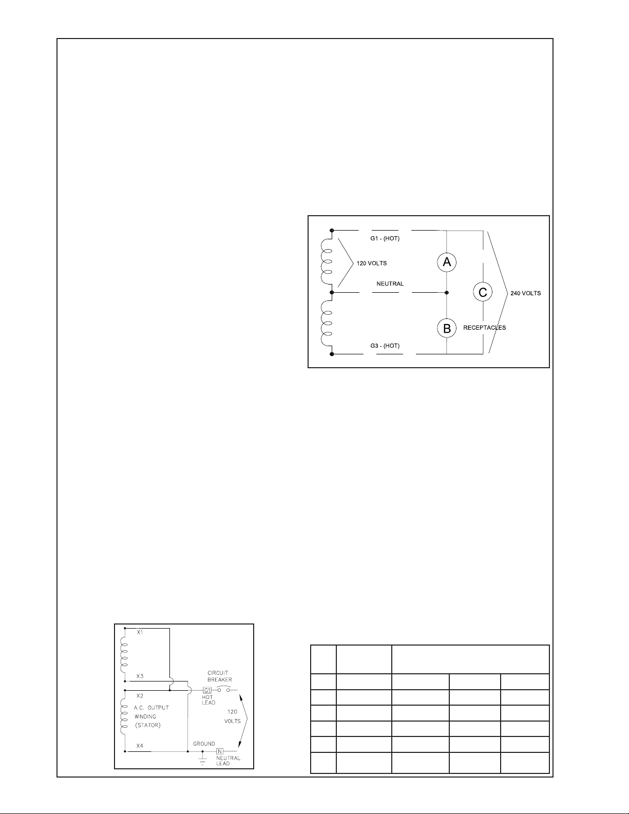
The diagram below represents a 4,000 watt generator. Only 2,000 watts at 120 volts (16.6 Amps) can
be taken from the generator at receptacle A and up
to 2,000 watts at 120 volts from receptacle C. On
an ordinary generator, CAUTION MUST BE EXERCISED TO PREVENT OVERLOADING EITHER OF
THE 120 VOLT CIRCUITS (A OR C).
UNIT CAPABILITIES
GENERATOR CONNECTIONS
This generator is designed for 120/240 volt alternating current (AC). Two circuit breaker protected
duplex outlets and one 240 volt twist lock receptacle
are provided for connection to various loads. This
generator can be spun in either direction.
FULL POWER 120 VOLT ONLY
This generator can be converted to full power 120
volt only. Replacement of the circuit breaker and
receptacle is required. A 30 amp 1-pole circuit
breaker and a 3-wire 30 amp twist-lock receptacle is
recommended for full power applications. See wiring schematic below.
STARTING ELECTRIC MOTORS
Electric motors require much more current (amps) to
start them than to run them. Some motors, particularly low cost split-phase motors, are very hard
to start and require 5 to 7 times as much current
to start them as to run them. Capacitor motors are
easier to start and usually require 2 to 4 times as
much current to start them as to run them. Repulsion Induction motors are the easiest to start and
require 1 1/2 to 2 1/2 times as much to start them as
to run them.
Most fractional horsepower motors take about the
same amount of current to run them whether they
are Repulsion Induction (RI), Capacitor (Cap), or
Split-Phase (SP) type. The chart below shows the
approximate current required to start and run various
types and sizes of 120 volt 60 cycle electric motors
under average load conditions.
HP AMPS
RUNNING
1/6 3.2 16 to 22 6 to 13 5 to 8
1/4 4.5 22 to 32 9 to 18 7 to 12
1/3 5.2 26 to 35 10 to 21 8 to 17
1/2 7.2 not made 14 to 29 11 to 18
1 13.0 not made 26 to 52 20 to 33
ST ARTING AMPS
SP CAP RI
12024-00
4
60706-225
Page 5

The fi gures given on the previous page are an aver-
age load such as a blower or fan. If the electric motor is connected to a hard starting load such as an
air compressor, it will require more starting current.
If it is connected to a light load, or no load such as a
power saw, it will require less starting current. The
exact requirement will also vary with the brand or
design of the motor.
Self-exiting generators respond to severe overloading differently than utility power. When overloaded,
the engine is not able to supply enough power to
bring the electric motor up to operating speed. The
generator responds with high initial starting current,
but the engine speed drops sharply. The overload
may stall the engine. If allowed to operate at very
low speeds, the electric motor starting winding will
burn out in a short time. The generator winding
might also be damaged.
CAUTION: EQUIPMENT DAMAGE
RUNNING THE GENERATOR SET UNDER THESE
CONDITIONS MAY RESULT IN DAMAGING THE
GENERATOR STATOR AS WELL AS THE MOTOR
WINDING.
Because the heavy surge of current required for
starting motors is required for only an instant, the
generator will not be damaged if it can bring the
motor up to speed in a few seconds of time. If diffi culty is experienced in starting motors, turn all other
electrical loads off and if possible reduce the load on
the electric motor.
this manual to insure that this unit meets your job
requirements.
UNIT INSTALLATION
Plans for installation should be prepared with proper
attention to mechanical and electrical engineering
detail to assure a satisfactory system installation.
The information in this manual is offered as a guide
to fi nalizing your installation plans. The installation
sequence is summarized below.
PLAN THE INSTALLATION
Generally these two-bearing generators are used on
portable equipment. For best service consider the
following:
1. All electrical equipment should be protected from
excessive moisture. Failure to do so will result in
deterioration of the insulation and short circuits and
grounds.
2. The generator should be installed in a sheltered
area. If the unit must be left in the open it should
always be protected with a weather cover such as a
tarp or large piece of canvas after each use to keep
out water and dust.
CAUTION: EQUIPMENT DAMAGE
Always allow the generator and prime mover to cool
before covering with a fl ammable weather covering.
MOUNTING
PREPARING THE UNIT
CAUTION: EQUIPMENT DAMAGE
UNPACKING
CAUTION: EQUIPMENT DAMAGE
When you unpack your new generator be sure to
remove all the information sheets and manuals from
the carton.
1. This generator was in good order when shipped.
Inspect the generator-set promptly after receiving
it. If any damage is noted, notify the transportation
company immediately; request proper procedures
for fi ling a “concealed damage” claim. Title to the
equipment and responsibility for fi ling a claim rests
with you when a generator-set is sent F.O.B. shipping point. Only you can legally fi le a claim.
2. Before proceeding with the preparations of
your new generator for operation, take a couple of
minutes to insure the unit you have received is the
correct model and review the specifi cation pages in
12024-00 60706-225
The generator must be mounted with the engine to a
common rigid base to prevent stress on the engine
and generator shafts and bearings due to vibration displacement. For permanent installations, the
engine-generator is usually mounted on a sub-frame
which can be shock mounted with special neoprene
pads on the main frame.
CAUTION: EQUIPMENT DAMAGE
Before proceeding with the installation, be sure that
you have completely read and understood the assembly and installation instructions.
An engine with adequate horsepower and a close
regulated (fi xed speed) governor is required for sat-
isfactory operation of this generator.
About 1.4 horsepower is required to produce each
1,000 watts of generator output power assuming
100% effi ciency of both the engine and the genera-
5
Page 6

tor. However, due to engine and generator effi cien-
cies of 80 to 90%, the loss of power due to engine
driving accessories such as cooling fans, battery
charging alternators, etc., friction losses and slippage
in the drive pullies and belts, the general conservative rule of thumb allowing approximately two (2)
horsepower for every 1,000 watts of generator output
is much more realistic. For example, this 2,000 watt
generator output will require a 4 or 5 H.P. engine
for full output, good speed/voltage regulation, and
satisfactory load performance. When determining the
prime mover/generator pulley ratio to drive the generator at the correct operating speed, bear in mind
that the power rating of most prime movers (usually
an engine) varies with the speed. It produces more
power at higher speeds, less when slowed. The
prime mover must be run fast enough to reach the
desired horsepower for good generator operation.
When the electrical load connected to the generator is increased, the engine is more heavily loaded
and as a result the speed drops slightly. This slight
decrease in speed together with the natural “voltage
drop” within the generator itself due to load current
and heating of the windings, results in a slightly
lower voltage than when the generator is running
idle.
The normal slight variations in speed also directly
affect the frequency of the output current. This
frequency variation has no appreciable effect in the
operation of most loads (such as motors, lights and
most small appliances). However, timing devices
and clocks will not keep perfect time unless the engine can keep the generator running at exactly 3600
RPM at all times. Since this is not usually possible,
minor time errors in clocks occur.
The drive belt system must be of adequate size and
must be tight enough to power the generator without
slippage. Be careful not to overtighten to the extent
that it puts excessive strain on the bearings. Doing
so can cause bearing failure and other possible damage to the generator.
Alignment of the generator to the prime mover is
important. Misalignment of the pulleys will cause excessive belt and pulley wear and unnecessary stress
on the prime mover.
The following table shows the effect of various operating speeds and electrical loads on a typical generator when matched and mounted to an adequate
prime mover.
Although individual units and models may vary
slightly, the normal voltage and frequency of typical
60 cycle engine-driven generators described in this
manual are approximately as follows when powered
by a typical prime mover (engine) run fi rst with no
load applied, then at half the generator capacity and
fi nally when loaded to its full capacity as rated on the
nameplate.
LOAD VS. OUTPUT
Generator
Load*
None 3690 61.5 129V
Half 3600 60.0 120V
Full 3510 58.5 115V
* NOTE: Required generator speed must be maintained at 3600 +/- 90 RPM under all load conditions.
All engines have a tendency to slow down when
a load is applied. The governor on the engine is
designed to hold the engine speed nearly constant.
Speed
(RPM)
Frequency
(Hz)
Voltage
The speed of the engine is usually adjusted so that
the generator produces proper voltage. If the adjustment is made “cold,” set the voltage a little higher
than normal since it will drop a few volts as the
generator warms up.
NOTE: When operating continuously at full load the
generator shell becomes very warm. It will be uncomfortable to the touch. This is normal for any high
performance inherently regulated generator. Output
voltage should be checked periodically to ensure
proper operation of the generator and appliances.
CAUTION: EQUIPMENT DAMAGE
Low voltage may damage any motors or appliances
connected to it. Running the generator at excessively high speeds results in too high voltage which
will also damage electrical devices connected to it.
Excessively high speed may also cause damage to
the generator armature windings.
CONNECTING THE LOADS
Applying The Load - A short warm-up time will
permit the engine to work more effi ciently when the
load is applied and will reduce the wear and extend
its life. Receptacles have been provided on the end
cover to connect the loads on this generator.
CAUTION: EQUIPMENT OVERLOAD
Keep the generator load within the generator and receptacle nameplate rating. Overloading may cause
damage to the generator and/or the loads.
Most electric tools and appliances will have the voltage and amperage requirements on their individual
nameplates. When in doubt consult the manufacturer or a local electrician. The nameplate amperage
12024-00
6
60706-225
Page 7

rating for electric motors can be misleading. See
“Starting Electric Motors” in Specifi cation Section.
These engine generator sets are inherently self
regulating based on engine speed. The engine governor will automatically adjust itself to the load. No
harm to the generator will result if it is operated with
no load connected.
Proper utilization amperage is necessary to prevent damage to either the receptacles/breakers or
the generator. The generator is a limited source of
electrical power, therefore pay special attention to
the receptacle and generator ratings. The nameplate rating can be obtained through a combination
of receptacles or a single receptacle as long as the
receptacle amperage rating is not exceeded. Both
the 120 and 240 volt output can be utilized at the
same time. See specifi cation section for proper load
separation.
Plug your tools such as drills, saws, blowers, sump
pump and other items to be powered directly into the
generator receptacles. Before plugging in all the
tools and cord sets, recheck the rating of the generator. Be sure it can handle the intended load and is
compatible with voltage, phase and current ratings.
‘Hard Wiring’ this unit directly into a temporary
construction site electrical system is NOT A SIMPLE
DO-IT-YOURSELF JOB. For your safety all wiring
must be done by a qualifi ed electrician and conform
to the National Electric Code and comply with all
state and local codes and regulations. Check with
local authorities before proceeding.
WARNING: PERSONAL DANGER
A fully isolated, double pole double throw manual
transfer switch must be installed any time a generator is being connected to an existing distribution
system.
CAUTION: EQUIPMENT DAMAGE
Failure to properly limit and balance the load applied
to the generator will cause the generator to produce
low voltage and may damage the engine generator
set. It may also cause severe damage to the loads
connected to the generator at that time. Improper
loading of the generator set constitutes abuse and
will not be covered by warranty.
225 S. CORDOVA AVE.
LECENTER, MN 56057
507-357-6821
SERVICE DEPT.
507-357-6831
12024-00 60706-225
7
Page 8

TROUBLESHOOTING CHART
SYMPTOM POSSIBLE CAUSE(S) CORRECTIVE ACTION
Low voltage. 1. Generator operating below
correct RPM speed.
2. Generator overloaded.
3. Defective stator
4. Defective rotor
Output voltage too high. Engine speed too high. See engine manual.
Generator overheating. 1. Generator overloaded.
2. Poor ventilation.
1. Generator must be operated at
3600 RPM +/- 90 RPM for proper
output voltage.
2. Reduce load to generator
nameplate.
3. Repair or replace stator.
4. Repair or replace rotor.
1. Reduce load.
2. Clear inlet and outlet air vents
of debris. If unit is housed, ensure
at least 2 ft. clearance on all sides
and that inlet and outlet vents are
of adequate size.
No output voltage. 1. Short in load.
2. Broken or loose wire.
3. Defective receptacles.
4. Defective capacitor.
5. Defective diode(s).
6. No residual magnetism in
generator.
7. Defective stator.
8. Defective rotor
WIRING SCHEMATIC
1. Disconnect load and fi nd fault
in load.
2. Repair or replace wire.
3. Replace receptacle(s).
4. Replace capacitor.
5. Replace diode(s).
6. Flash the fi eld.
7. Repair or replace stator.
8. Repair or replace rotor.
12024-00
8
60706-225
Page 9

ILLUSTRATED PARTS LIST
12024-00 60706-225
9
Page 10

OUTLINE DRAWING
12024-00
10
60706-225
Page 11

END COVER ASSEMBLY
& WIRING CONNECTIONS
12024-00 60706-225
11
Page 12

12 MONTH LIMITED WARRANTY
WINCO, Incorporated warrants to the original purchaser for 12 months that goods
manufactured or supplied by it will be free from defects in workmanship and material,
provided such goods are installed, operated and maintained in accordance with WINCO
written instructions.
WINCO’s sole liability, and Purchaser’s sole remedy for a failure under this warranty,
shall be limited to the repair of the product. At WINCO’s option, material found to be
defective in material or workmanship under normal use and service will be repaired or
replaced. For warranty service, return the product within 12 months from the date of
purchase, transportation charges prepaid, to your nearest WINCO Authorized Service
Center or to WINCO, Inc. at LeCenter Minnesota.
THERE IS NO OTHER EXPRESS WARRANTY.
To the extent permitted by law, any and all warranties, including those of merchantability
and fi tness for a particular purpose, are limited to 12 months from date of purchase. In
no event is WINCO liable for incidental or consequential damages.
Note: Some states do not allow limitation on the duration of implied warranty and some
states do not allow the exclusion or limitation of incidental or consequential damages, so
the above limitations may not apply in every instance. This warranty gives you specifi c
legal rights which may vary from state to state.
WINCO reserves the right to change or improve it products without incurring any obligations to make such changes or improvements on products purchased previously.
EXCLUSIONS:
WINCO does not warrant Engines. Engines are covered exclusively by the warranties
of their respective manufacturers, see enclosed warranties.
WINCO does not warrant Component Parts that are warranted by their respective manufacturers.
WINCO does not warrant modifi cations or alterations which were not made by WINCO
Inc.
WINCO does not warrant products which have been subjected to misuse and/or negligence or have been involved in an accident.
This warranty does not include travel time, mileage, or labor for removal or reinstallation
of WINCO product from its application.
12024-00
12
60706-225
 Loading...