

Page 1
PACKAGE
PSS60/D
STANDBY
SYSTEMS
PSS90/D
DSE7310
INSTALLATION AND
OPERATORS MANUAL
Page 2

SAVE THESE INSTRUCTIONS
This manual contains important instructions
that should be followed during installation and
maintenance of the generator and batteries.
Read and understand all instructions in the manual
before starting and operating the generator set.
USING THIS MANUAL
Congratulations on your choice of a Winco generator set.
You have selected a high-quality, precision-engineered
generator set designed and tested to give you years of
satisfactory standby service.
To get the best performance from your new engine
generator set, it is important that you carefully read and
follow the operating instructions in this manual.
Should you experience a problem please follow the
“Things To Check” near the end of this manual. The
warranty listed in this manual describes what you can
expect from WINCO should you need service assistance
in the future.
COPY YOUR MODEL AND SERIAL NUMBER
HERE
No other WINCO generator has the same serial number
as yours. It is important that you record the number and
other vital information here. If you should ever need to
contact us on this unit it will help us to respond to your
needs faster.
MODEL_____________________________________
SERIAL NUMBER____________________________
PURCHASE DATE____________________________
DEALER____________________________________
TABLE OF CONTENTS
INTRODUCTION 2
GUIDE TO PRODUCT SAFETY 3
BASIC INFORMATION 4
Description 4
DSE 7310 Engine Control 5
Specication Table 5
PREPARING THE UNIT
Unpacking the unit 6
ENGINE GENERATOR INSTALLATION
Installation 6
Fuel Line Installation 7
Fuel Pressure Tables 7
LP Liquid Withdrawal 8
Lubrication 8
Coolant 8
Battery Installation 9
Battery Charger/Block Heater Wiring 9
AC Electrical Connections 10
DC Electrical Connections 11
ENGINE CONTROL PANEL LAYOUT 13
DSE 7310 CONTROLLER 13
INITIAL START-UP 14
START-UP PROCEDURE 14
EXERCISER CLOCK 15
TROUBLESHOOTING INFORMATION 15
CHANGING THE FUEL TYPE 16
GENERATOR END SPECIFICATION 16
ENGINE SPECIFICATIONS 17
ENGINE MAINTENANCE SCHEDULE 18
VOLTAGE REGULATOR WIRING 19
AC WIRING - THREE PHASE
277/480 Volt 20
120/208 Volt 20
120/240 Volt 21
AC WIRING - SINGLE PHASE
120/240 Volt 21
DC SCHEMATIC - WIRING DIAGRAM 22
OUTLINE DRAWING 23
12 MONTH WARRANTY 24
PROPER USE AND INSTALLATION
You must be sure your new engine generator set is:
* Properly serviced before starting
* Operated in a well ventilated area
* Properly exhausted and gases safely dispersed
* Wired by a qualied electrician
* Operated only for its designed purposes
* Used only by operators who understand its
operation
* Properly maintained
2
4228-0060706-251
Page 3

IMPORTANT SAFETY
INSTRUCTIONS
SAVE THESE INSTRUCTION
This manual contains important instructions
that should be followed during installation and
maintenance of the generator and batteries.
Read and understand all instructions in the manual
before starting and operating the generator set.
This engine generator set has been designed and manufactured
to allow safe, reliable performance. Poor maintenance, improper
or careless use can result in potential deadly hazards; from
electrical shock, exhaust gas asphyxiation, or re. Please read
all safety instructions carefully before installation or use. Keep
these instructions handy for future reference. Take special note
and follow all warnings on the unit labels and in the manuals.
ANSI SAFETY DEFINITIONS
************************************************************
DANGER:
DANGER indicates an imminently hazardous situation which,
if not avoided, will result in death or serious injury. This signal
word is to be limited to the most extreme situations.
************************************************************
************************************************************
WARNING:
WARNING indicates a potentially hazardous situation which, if
not avoided, could result in death or serious injury.
************************************************************
************************************************************
CAUTION:
CAUTION indicates a potentially hazardous situation which, if not
avoided, may result in minor or moderate injury. It may also be
used to alert against unsafe practices.
************************************************************
NOTE:
CAUTION is also used on the unit labels and in this manual
to indicate a situation that could result in serious damage or
destruction of the equipment and possible personal injury.
1. ELECTRIC SHOCK - The output voltage present in this
equipment can cause a fatal electric shock. This equipment
must be operated by a responsible person.
a. Do not allow anyone to operate the generator without
proper instruction.
b. Guard against electric shock.
c. Avoid contact with live terminals or receptacles.
d. Use extreme care if operating this unit in rain or snow.
e. Use only three-prong grounded receptacles and
extension cords.
f. Be sure the unit is properly grounded to an external
ground rod driven into the earth.
2. FIRE HAZARD - Natural gas and L.P. present a hazard of
possible explosion and/or re.
a. Do not smoke or use open ame near the generator
set.
b. Keep a re extinguisher nearby and know its proper use.
Fire extinguishers rated ABC by NFPA are appropriate.
3. DEADLY EXHAUST GAS - Exhaust fumes from any gaso-
line engine contain carbon monoxide, an invisible, odorless
and deadly gas that must be mixed with fresh air.
a. Operate only in well ventilated areas.
b. Never operate indoors.
c. Never operate the unit in such a way as to allow exhaust
gases to seep back into closed rooms (i.e. through
windows, walls or oors).
4. NOISE HAZARD - Excessive noise is not only tiring, but
continual exposure can lead to loss of hearing.
a. Use hearing protection equipment when working
around this equipment for long periods of time.
b. Keep your neighbors in mind when permanently install ing this equipment.
5. CLEANLINESS - Keep the generator and surrounding area
clean.
a. Remove all grease, ice, snow or materials that create
slippery conditions around the unit.
b. Remove any rags or other material that could create
potential re hazards.
c. Carefully wipe up any gas or oil spills before starting the
unit.
d. Never allow leaves or other ammable material to build
up around the engine exhaust area.
6. SERVICING EQUIPMENT - All service, including the
installation or replacement of service parts, should be
performedonlybyaqualiedtechnician.
a. Use only factory approved repair parts.
b. Do not work on this equipment when fatigued.
c. Never remove the protective guards, cover, or recep tacle panels while the engine is running.
d. Use extreme caution when working on electrical compo nents. High output voltages from this equipment can
cause serious injury or death.
e. Always avoid hot mufers, exhaust manifolds, and
engine parts. They all can cause severe burns instantly.
f. Installing a generator set is not a “do-it-yourself” project.
Consult a qualied, licensed electrician or contractor.
The installation must comply with all national, state, and
local codes.
g. Always make sure unit is disabled before placing your
hands anywhere near the fan, belts, alternator or water
hoses.
34228-00
60706-251
Page 4
TESTING POLICY:
Before any generator is shipped from the factory, it is fully
checked for performance. The generator is loaded to its full
capacity, and the voltage, current, and frequency are carefully
checked.
Rated output of generators is based on engineering tests of
typical units, and is subject to, and limited by, the temperature,
altitude, fuel, and other conditions specied by the manufacturer
of the applicable engines.
INTRODUCTION AND
DESCRIPTION
With the addition of an Automatic Transfer Switch this packaged
standby system includes all items necessary for a completely
automatic standby power system.
DESCRIPTION
This package power system is designed to automatically provide
standby power to unattended loads during electrical outages.
Upon an interruption of normal electrical service this package
power system’s electrical control circuits will automatically start
the engine. The generator will produce electrical power and the
Automatic Transfer Switch (A.T.S.) will automatically transfer the
electrical loads to the engine-generator set. Upon restoration
of normal electrical service the A.T.S. will sense return of the
normal commercial power and retransfer the load back to normal
commercial power source. The engine control circuits shut off the
run signal to the engine generator set.
2) ENGINE/GENERATOR
PSS60- The engine generator set consists of a GM 5.7L, V-8
industrial, liquid-cooled engine equipped to run on L.P./N.G. fuel.
The engine operates at 1800 rpm and frequency regulation is
maintained by the electronic governor within .5 cycles variation,
from no load to rated load. The 60,000 watt (60kW) generator is
a single bearing, direct drive, rotating eld design. The generator
is connected to the engine ywheel via exible drive disks.
The engine generator is mounted in a weather proof enclosure
for outside installation. Connection boxes are provided to all
customer connections (both AC output and DC control). A
customer supplied 12 Volt, 650 CCA (BCI group 24) battery
is required to complete the installation. Engine operation is
controlled by a Deep Sea (DSE) engine control mounted in the
engine generator enclosure.
PSS90 - The engine generator set consists of a GM 5.7L,
Turbocharged/Aftercooled V-8 industrial, liquid-cooled engine
equipped to run on L.P./N.G. fuel. The engine operates at
1800 rpm and frequency regulation is maintained by the engine
governor within .5 cycles variation, no load to rated load. The
90,000 watt (90kW) generator is a single bearing, direct drive,
rotating eld design. The generator is connected to the engine
ywheel via exible drive disks. The engine generator is
mounted in a weather proof enclosure for outside installation.
Connection boxes are provided to all customer connections
(both AC output and DC control). A customer supplied 12 Volt,
650 CCA (BCI group 24) battery is required to complete the
installation. Engine operation is controlled by a Deep Sea (DSE)
engine control mounted in the engine generator enclosure.
** NOTICE **
These units will automatically transfer if a power outage occurs
while running in an exercise mode.
These package power systems consist of two major
components:
1) AUTOMATIC TRANSFER SWITCH (UL LISTED)
The Automatic Transfer Switches (A.T.S.) is a wall mount switch
designed for inside installation. An electronic exerciser circuit
is installed in the A.T.S. as standard equipment. The A.T.S. also
contains the power failure sensing circuitry necessary to send
a start/stop signal to the engine generator set. The following
is a list of recommended A.T.S. sizes for each model. Outside
switches as well as additional sizes are available, consult your
sales rep for additional information.
RECOMMENDED
MODEL VOLTAGE ATS AMPERAGE
PSS60-3 120/240 400
PSS60-4 120/208 400
PSS60-17 120/240 200
PSS60-18 277/480 100
PSS90-3 120/240 400
PSS90-4 120/208 400
PSS90-17 120/240 400
PSS90-18 277/480 200
ENGINE CONTROL MODULE (DSE 7310 Series)
The DSE 7310 Series control modules provide integrated engine
and generator set control, protection and metering in a single
package. Microprocessor based technology allows for exact
measurement, set point adjustment, and timing functions. Front
panel controls and indicators enable quick and simple operation.
Fully congurable via PC software, allows units to be easily
customized for each application. Includes selected front panel
programming for on site changes. A wide temperature-range
liquid crystal display (132 x 64) with backlighting can be viewed
under a wide range of ambient light and temperature conditions.
FEATURES
DSE 7310 Control Modules have the following features:
Local and Remote Generator Control
Engine and Generator Protection
CAN Bus Compatible
Programmable Logic
Five-key Menu Navigation
Engine Exercise Mode
Automatic Transfer Switch Control (Mains Failure)
User Selectable RS232 & RS485 (Remote Operation)
Additional optional A.T.S. sizes are available to meet specic
needs. Contact your local WINCO dealer or the WINCO Sales
Department for a quote.
4
4228-0060706-251
Page 5
FUNCTIONS
DSE 7310 Series Control Modules perform the following
protection and metering functions:
Generator Protection and Metering
Generator protection includes over voltage, under voltage,
under frequency, over frequency and overload protection. Each
generator protection function has an adjustable pickup and time
delay setting. Metered generator parameters include voltage,
current, real power (watts), power factor (PF)
Engine Protection and Metering
Engine protection features include oil pressure and coolant
temperature monitoring, over crank protection, ECU specic
protection elements, and diagnostic reporting.
FUEL CONSUMPTION
NG LP VAPOR
(1,000 BTU/CU FT) (2,520 BTU/CU FT)
MODEL CF/HRBTU/HR #/HR GAL/
PSS60 799 799,000 39.4 9.29 334 850,964
PSS90 1230 1,230,000 52.6 12.4 446 1,149,00
CF/HRBTU/HR
HR
L.P. TANK SIZING
Minimum required L.P. Tank size for L.P. Vapor withdrawal
operating at various outside temperatures given in degrees
Fahrenheit (Celsius)
Metered engine parameters include, oil pressure, coolant
temperature, battery voltage, speed, engine load, coolant level
(from ECU), ECU specic parameters, and run-time statistics.
** NOTICE **
These units will automatically transfer if a power outage occurs
while running in an exercise mode.
SPECIFICATIONS
LP RATING
MODEL WATTS VOLTS AMP HZ PH RPM
PSS60-3 56,000 120/240 233* 60 1 1800
PSS60-4 60,000 120/208 208** 60 3 1800
PSS60-17 60,000 120/240 180** 60 3 1800
PSS60-18 60,000 277/480 90** 60 3 1800
PSS90-3 80,000 120/240 333* 60 1 1800
PSS90-4 80,000 120/208 278** 60 3 1800
PSS90-17 80,000 120/240 240** 60 3 1800
PSS90-18 80,000 277/480 120** 60 3 1800
TANK TEMPERATURE
MODEL 60 F(16 C) 30 F(0 C) 0 F(-18 C) -20 F(-29 C)
PSS60 500 Gal 1000 Gal 2000 Gal* 5000 Gal*
PSS90 500 Gal 1000 Gal 2000 Gal* 5000 Gal*
*Recommend liquid withdrawal at these temperatures.
ENGINE SPECIFICATIONS:
** NOTICE **
Regarding Engines - This manual covers the generator portion
of these units. See the separate engine instruction manual
for engine-related problems, detailed engine information and
engine warranty. Refer to engine operating and maintenance
instructions
** CAUTION **
EQUIPMENT DAMAGE - Be sure to check the engine oil level
frequently as specied in the engine manual.
The engine manufacturer has established an excellent worldwide
engine service organization; engine service is available from a
nearby authorized dealer or distributor. Go to the WINCO web
site for a list of engine dealers. (http://www.wincogen.com/
Engine_Support/ )
NG RATING
MODEL WATTS VOLTS AMP HZ PH RPM
PSS60-3 55,000 120/240 229* 60 1 1800
PSS60-4 58,000 120/208 201** 60 3 1800
PSS60-17 58,000 120/240 174** 60 3 1800
PSS60-18 58,000 277/480 87** 60 3 1800
PSS90-3 90,000 120/240 375* 60 1 1800
PSS90-4 90,000 120/208 312** 60 3 1800
PSS90-17 90,000 120/240 270** 60 3 1800
PSS90-18 90,000 277/480 135** 60 3 1800
*Unity Power Factor - Derate 3.5% per 1000 feet elevation above
sea level.
**Power Factor .8 - Derate 3.5% per 1000 feet elevation above
sea level.
The rated power of each engine-generator is limited by the
temperature, altitude and all other ambient conditions specied
by the engine manufacturer. Engine power will decrease 3-1/2%
for each 1000 ft. above sea level, and will decrease an additional
1% for each 10o Fahrenheit above 60o Fahrenheit. Units should
not be operated in ambient temperature greater than 104o F.
54228-00
60706-251
Page 6

UNPACKING INSTRUCTIONS
** NOTICE **
When unpacking the generator set, be sure to inspect it carefully
for freight loss or damage. If loss or damage is noted at the
time of delivery, require that the person making the delivery
make note of the loss or damage on the freight bill, or afx his
signature under the consignees’s memo of the loss or damage.
Contact the carrier for claim procedures.
INSTALLATION
****************
***** WARNING *****
****************
PERSONAL INJURY - Before proceeding with the installation,
be sure the operation selector switch is in the “stop” position.
General Information
When loss or damage is noted after delivery, segregate the
damaged material, and contact the carrier for claim procedures.
“Concealed Damage” is understood to mean damage to the
contents of a package which is not in evidence at the time of
delivery by the carrier, but which is discovered later. The carrier
or carriers are responsible for merchandise lost or damaged
in transit. The title to goods rests with the consignee when
generators are shipped FOB factory, and only the consignee can
legally le a claim.
**** CAUTION ****
EQUIPMENT DAMAGE - These units are shipped with oil, and
a 50/50 mix of coolant. Be sure to check all uid levels before
operating. See engine manufacturer’s instruction manual for
recommended oil requirements before initial starting.
UNPACKING:
1. Carefully remove the carton.
2. After inspecting the engine-generator for external physical
damage, check for the following items packed inside the
carton:
a. Owner’s manual and wiring diagram.
b. Engine manufacturer’s instruction manual.
3. Remove main frame hold down bolts, (6).
4. Unit can now be lifted from shipping rails.
Note:Roofaccesspanelshavebeenprovidetocheck/ll
the engine oil and the coolant. Side panels are equipped
with door latches for their removal. All the door latches are
keyed with a common key.
These engine generator sets are for outdoor installation. These
units must be bolted solidly to a concrete pad. The transfer
switch is mounted next to your distribution panel inside the
building. Consult a qualied, licensed electrician or contractor to
install and wire the transfer switch. The installation must always
comply with all national, state, and local codes.
***** CAUTION *****
EQUIPMENT DAMAGE - These units must be mounted on a
solid concrete pad to prevent air from exiting under the unit.
Allowing air to exit under the unit may cause the unit to overheat
from lack of proper air ow.
Before beginning the installation process recheck the rating
of the generator set and its transfer switch rating. Be certain
they can handle the intended load and are compatible with
the entrance voltage, phase and current ratings. Plans
for installation should be prepared with proper attention to
mechanical and electrical engineering detail to assure a
satisfactory system installation. The information in this manual
is offered only as a guide to nalizing your installation plans. For
full service switching the A.T.S. must have a fusible disconnect
(circuit breaker) installed before the switch to protect the
contacts.
ENGINE GENERATOR SET MOUNTING
The unit’s main frame should be bolted solidly to a 4 to 6 inch
thick cement pad. The engine-generator is mounted on a subframe which is attached with special shock mounts to the main
frame. This allows the engine-generator free movement without
affecting the control panel which is mounted on the main frame.
Do not shock mount the main frame. Engine vibration will be
transmitted to the control panel causing erroneous start/stop
cycles and premature control failure.
These units should be mounted a minimum of 24” from a
structure. This will allow for ample room to maintain and work
on the generator set. Units must be installed in accordance with
all local, state, and national codes. Consult your local agency
having jurisdiction for specic requirements.
6
4228-0060706-251
Page 7
FUEL INSTALLATION
The fuel supply should be as close as possible to the engine.
This will reduce the installation cost of fuel runs. The information
in this manual is offered to assist you in providing the proper fuel
for your engine. However, this information is only provided to
inform you of the engine’s requirements and assist in making you
aware of the decisions you must make. In no case should the
instructions or information provided be interpreted to conict with
any local, state or national codes. If in doubt, always consult
your local re marshal or gas supplier.
****************
***** WARNING *****
****************
FIRE HAZARD - All fuel runs should be installed by a licensed
fuel supplier.
Connect the fuel supply to the inlet of the fuel solenoid (see
table for recommended line size). The pressure at the demand
regulator must be four to six ounces per square inch or 7 to 11
inches W.C. (Water column) on vapor withdrawal units. On units
equipped with liquid withdrawal fuel systems full tank pressure
is plumbed to the fuellock strainer mounted on the generator
rails. The fuel converter mounted on the unit will handle both
vaporization of the fuel and pressure reduction.
****************
***** WARNING *****
****************
PERSONAL DANGER - Do not use galvanized pipe in fuel line
runs. The galvanized coating can become eroded and ake off,
causing possible obstructions in the regulator or fuel valve. The
results could range from inoperative engine start to hazardous
fuel leaks.
Size of pipe normally required for generators operating on NG/
LP:
UP TO
25 FEET*
PSS60 1.25” pipe NOT
PSS90 1.25” pipe NOT
* Allow an additional 3 feet for each standard elbow.
Do not use ‘street ells’ (restrictive).
** USE THE TWO REGULATOR SYSTEM SHOWN BELOW.
OVER
25 FEET
RECOMMENDED**
RECOMMENDED**
**** CAUTION ****
EQUIPMENT DAMAGE - Be careful when sealing gas line joints.
Excessive sealing compound can be drawn into the solenoid,
regulator or carburetor causing an engine malfunction.
INSTALLING THE FUEL LINE
** NOTICE **
The engine generator sets are properly adjusted before they
leave the factory for a specic fuel, either NG (natural gas), LP
(liquid propane vapor) or LPG (liquid withdrawal propane). This
fuel type is noted in your model number. If it becomes necessary
to change the fuel type in the eld see information on page 16.
Line Size (vapor system)
Unit location will determine the size of fuel line that is required
to supply the engine with a constant fuel pressure. Refer
to the tables below for fuel line size, fuel consumption and
recommended tank size. For distances of 25 feet and over, a
two regulator fuel system is recommended. This is accomplished
by installing a primary regulator at the tank which will reduce the
tank pressure down to 10 to 15 lbs. A secondary regulator is
installed to further reduce the fuel pressure to the required six (6)
oz operating pressure. This secondary regulator must be at least
10 feet from the engine generator set. Any closer installation
will require a larger line be installed to provide a fuel reservoir.
If this is not done, the demand regulator on the unit and the
pressure regulator in the fuel line will interfere with each other.
When this two (2) stage regulator system is used, a fuel line size
of 3/4 to 1 inch is generally adequate for distances up to 300 feet
from the primary to the secondary regulator. (Consult your local
fuel supplier for your exact requirements). The appropriate line
size from the table below is then installed from the secondary
regulator to the generator set.
FUEL PRESSURE (vapor system)
Correct fuel pressure cannot be stressed enough. The most
common cause for inoperative systems is an inadequate or
incorrect fuel pressure. Power and performance of the engine
is in direct relation to the correctness of the fuel system. Shown
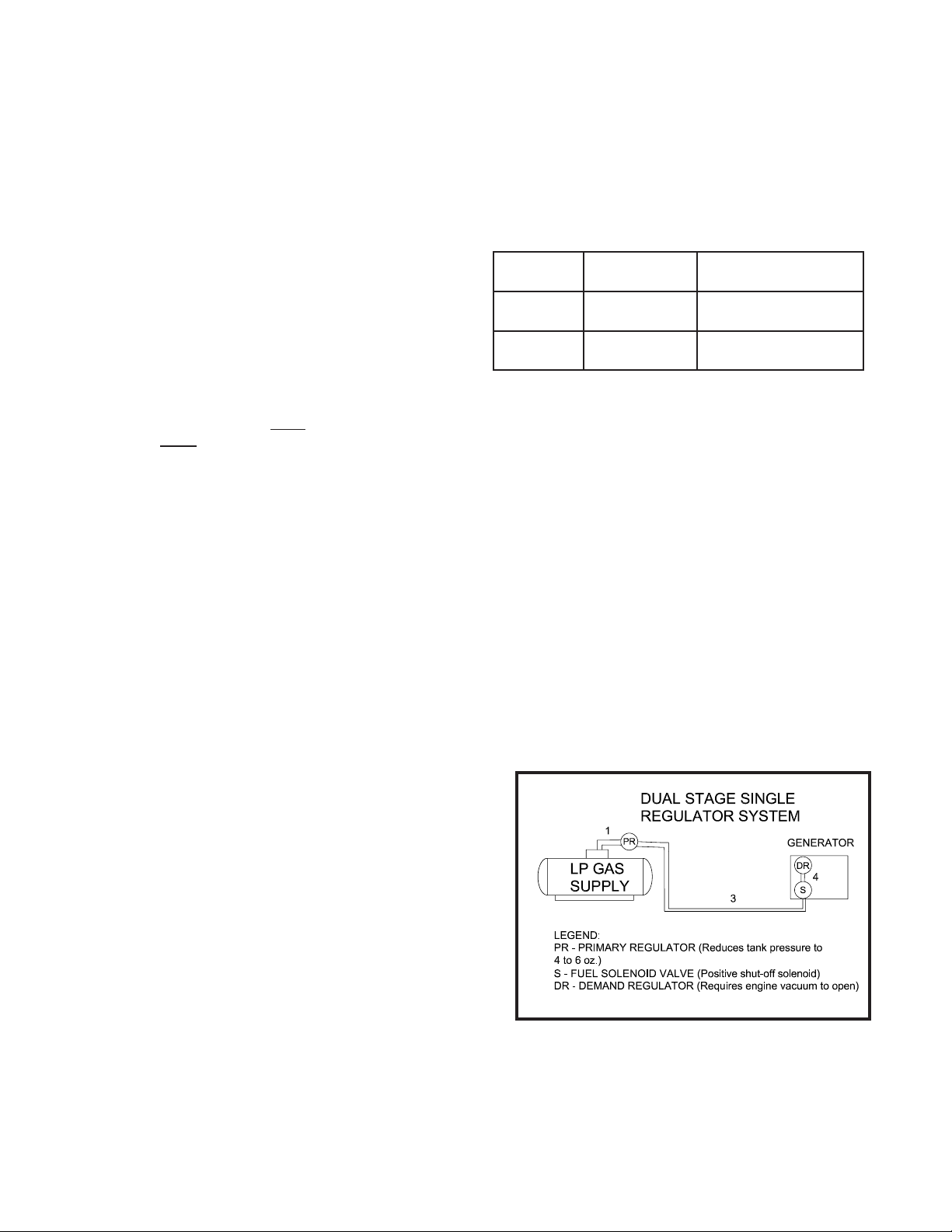
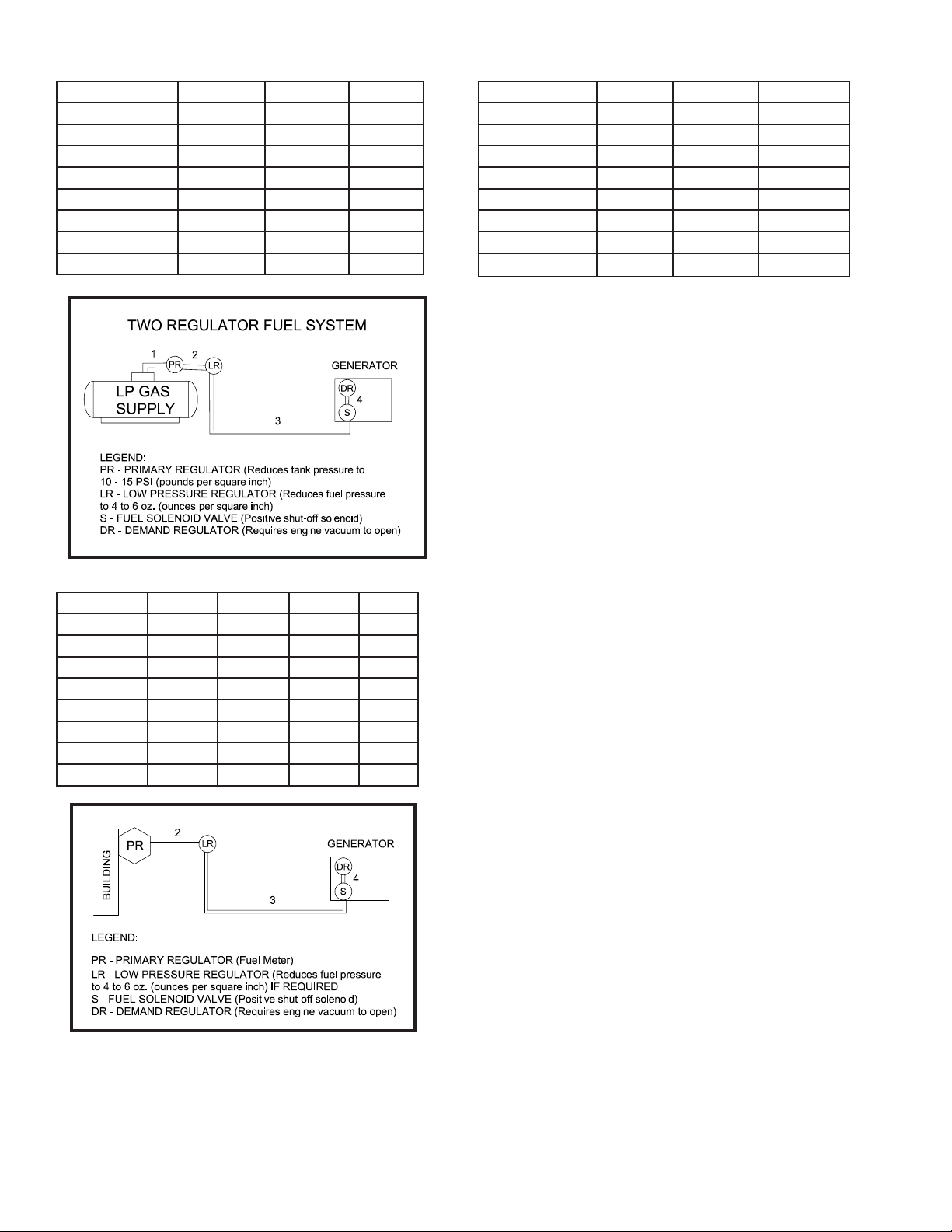
below is a diagram of a typical L.P. or N.G. installation.
Reference numbers 1 through 3 in the diagrams below are
system parts supplied by customer.
Reference number 4 is the engine generator set.
Below is a table of the fuel pressure reading at each reference in
the system.
Fuel Pressure Table
74228-00
60706-251
Page 8
Single Regulator (L.P. Vapor only)
1 3 4
UNIT OFF TANK PSI 7-11 in 7-11 in
4-6 oz 4-6 oz
STARTING TANK PSI 7-11 in 7-11 in
4-6 oz 4-6 oz
NO LOAD TANK PSI 7-11 in 7-11 in
4-6 oz 4-6 oz
FULL LOAD TANK PSI 7-11 in 7-11 in
4-6 oz 4-6 oz
Natural Gas
2 3 4
UNIT OFF LINE PSI 7-11 in 7-11 in
4-6 oz 4-6 oz
STARTING LINE PSI 7-11 in 7-11 in
4-6 oz 4-6 oz
NO LOAD LINE PSI 7-11 in 7-11 in
4-6 oz 4-6 oz
FULL LOAD LINE PSI 7-11 in 7-11 in
4-6 oz 4-6 oz
Notice the preceding tables give two (2) different units of
measuring fuel pressure. The rst is with a pressure gauge
calibrated in ounces per square inch. The second and most
accurate is the use of a simple water manometer. A manometer
is calibrated in inches of water column.
Remember that whichever fuel delivery system or type of vapor
fuel used, the fuel pressure at the demand regulator installed on
the engine generator must be between 4 and 6 oz. (7-11 inches
of water column). Any lower pressure and the unit will starve
for fuel under load. Any higher and the unit may ‘ood’ when
attempting to start.
Two (2) Regulator System (L.P. Vapor only)
1 2 3 4
UNIT OFF TANK PSI 10-15 lbs 7-11 in 7-11 in
4-6 oz 4-6 oz
STARTING TANK PSI 10-15 lbs 7-11 in 7-11 in
4-6 oz 4-6 oz
NO LOAD TANK PSI 10-15 lbs 7-11 in 7-11 in
4-6 oz 4-6 oz
FULL LOAD TANK PSI 10-15 lbs 7-11 in 7-11 in
4-6 oz 4-6 oz
LP LIQUID WITHDRAWAL SYSTEMS
When installing a unit equipped the LP liquid withdrawal a
primary regulator is not required on the supply tank. The supply
line is connected to a liquid withdrawal valve on the supply
tank and runs directly to the fuellock strainer mounted on the
engine generator set. Normally a 3/8 to 1/2 inch copper line is
acceptable for this type of fuel installation. You must be sure
that the valve you have connected to on the supply tank is in
fact a liquid supply valve and has a drop tube inside the tank
that is pulling fuel from the bottom of the supply tank. Before
starting the unit you must conrm that you have a good liquid
supply at the unit. Engine generator sets equipped for liquid
withdrawal will not run properly when supplied with high
pressure vapor fuel.
LUBRICATION
Before starting the engine, check the oil level in the crankcase.
If it is low, rell to the full mark with the proper weight/grade of
oil as recommended by the engine manufacturer’s maintenance
instructions. The necessity of using the correct oil, and keeping
the crankcase full cannot be over emphasized. Failure to use
the proper oil and keep the crankcase properly lled will cause
excessive engine wear and shorten its useful life.
COOLANT
Before starting the engine, check the coolant level in radiator.
If it is low, rell as specied in the engine manufacturer’s
maintenance instructions. The radiator should be lled to about
1 inch below the ller neck. For additional information on engine
coolant requirements see engine manufacturer’s maintenance
instructions.
8
4228-0060706-251
Page 9

INSTALLING THE BATTERY
**** CAUTION ****
In the following battery installation procedure, check to be sure
the selector switch remains in the “stop” position. This should be
your last step before initial start-up.
A customer supplied twelve-volt battery is required to complete
the installation. Installation of the highest CCA rated battery,
within the correct BCI group, will increase cold weather starting
performance. Gel batteries should not be used with the battery
tender installed in the generator enclosure.
Model Voltage BCI
Group
PSS60 12 24 650
PSS90 12 24 650
Installation and servicing of batteries must only be performed
or supervised by personnel knowledgeable of batteries and the
required precautions. Keep unauthorized personnel away from
batteries.
MINIMUM
CCA Rating
WARNING – The electrolyte is a diluted sulfuric acid that is
harmful to the skin and eyes. It is electrically conductive and
corrosive. The following precautions must always be taken.
* Always wear full eye protection and protective clothing.
* Where electrolyte contacts the skin, wash off immediately
with water.
* If electrolyte contacts the eyes, ush thoroughly and immedi
ately with water and seek immediate medical attention.
* Spilled electrolyte is to be washed down with an acid
neutralizing agent. A common practice is to use a solution
of one pound of bicarbonate of soda (baking soda) to one
gallon of water. The bicarbonate of soda solution is to be
added until the evidence of reaction, foaming, has ceased.
The resulting liquid is to be ushed with water and the area
dried.
DANGER – Explosive Fire Risk
* Never smoke when near batteries.
* Do not cause a ame or spark in the battery area.
* Always discharge static electricity from your body before
touching batteries by rst touching a grounded metal surface.
When installing or replacing batteries, use the proper group/size
starting battery. The battery should be a Maintenance Free
lead acid design. Deep cycle batteries will not work for this
application.
CAUTION – PERSONAL DANGER
CAUTION - NEVER dispose of a battery in a re. The battery is
capable of exploding.
CAUTION - DO NOT open or mutilate the battery. Released
electrolyte is known to be harmful to the skin and eyes and to be
very toxic.
These engine generator sets are all NEGATIVE ground. Be very
careful not to connect the battery in reverse polarity, as this may
short circuit the battery charging system on the engine.
CAUTION – A battery presents a risk of electrical shock and high
short circuit current. The following precautions must be observed
when working with batteries.
1. Remove watches, rings and other metal objects.
2. Use tools with insulated handles.
3. Check both the battery cable ends and the battery posts to
be sure they are free of corrosion.
4. Always connect the battery positive cable rst and then
connect the battery negative cable. When removing the
battery cables from the battery reverse the procedure,
disconnect the negative cable rst and then the positive
cable.
5. Be sure all connections are tight and coat the terminals and
cable end with dialectic grease.
SERVICING BATTERIES
Batteries used on these units may over time lose water. This is
especially true if you are using a trickle charger to maintain your
battery. When relling the battery with water use only distilled
water. Tap water will shorten the service life of the battery.
Never ll the battery above the ll line. Over lling above the
upper level line may cause the electrolyte to overow, resulting in
corrosion to the engine or nearby parts. Immediately wash off
any spilled electrolyte following the procedure above.
NOTE: Always make sure that a new battery is fully charged
before installing it on a generator set. Failure to do so can cause
damage to the engine control module in the generator set.
All connections must be clean and tight. Check the electrolyte
(uid) in the battery periodically to be sure it is above the plates.
Never allow the battery to remain in a discharged condition.
CONNECTING THE BATTERY CHARGER &
BLOCKHEATER
A three-stage battery charger is provided standard for all 12 volt
standby systems. The standard charger is an Automatic Battery
Charger & Maintainer. This Charger has three rates of charging.
During the rst stage, know as BULK Charging, the charging
current is limited to 2 Amps at a voltage of up to 14.5 volts. The
green LED will blink during this stage. During stage two, know
as ABSORPTION Charging, the charging voltage is held at
14.5 volts and the charging rate gradually reduces the amount
of current (amps) owing to the battery. The green LED will also
blink during this stage. Stage three is called MAINTENANCE
Charging. During this stage the voltage will drop to 13.3 volts and
the charge rate will drop to as low at .1 amps. This keeps your
batteries in a fully charged condition without over charging them.
During this stage the green LED is constantly lit. There are
optional 5 and 10 amp chargers available that may be installed
on some units
94228-00
60706-251
Page 10

** NOTICE **
The trickle charger is not intended to recharge a battery which
has become completely discharged. It is designed to produce
just enough current to maintain a fully charged battery.
The battery tender receptacle is to be powered by a GFCI circuit
and installed in accordance with the United States National
Electric Code. These AC wires can be run in the same conduit
as the other AC leads from the generator. It is suggested that
this circuit be fused for 15 amps, then both the battery charger
and the block heater can be connected to the same circuit. A
120 volt duplex receptacle is mounted on the generator along
side circuit breaker panel, the battery tender is shipped already
plugged into the receptacle.
The engine blockheater installed on this unit should also be
plugged in this receptacle. The block heater is thermostatically
controlled and when plugged in will maintain the engine coolant
temperature between 100 and 120 degrees F.
MOUNTING THE AUTOMATIC
TRANSFER SWITCH (A.T.S.)
****************
***** WARNING *****
****************
FIRE HAZARD - All wiring must be done by a licensed
electrician, and must conform to the national electrical code and
comply with all state and local codes and regulations. Check
with the local authorities before proceeding!
A.C. ELECTRICAL
CONNECTIONS
NOTICE - CLASS 1 WIRING METHODS ARE TO BE USED
FOR ALL FIELD WIRING CONNECTIONS TO TERMINALS
OF A CLASS 2 CIRCUIT
INSTALLERS NOTE: To access the AC and DC
interconnections on this unit, open the single door
on the right hand side of the units. Then remove the
safety panel covering the mainline circuit breaker. All
connection are behind this panel.
INSTALLATION NOTES
Because of the many different types of service, feeder, and
distribution equipment, no specic wiring instructions can be
provided. It is recommended that only copper wire be used.
In all cases it is essential that while the load is connected to
the generator, there can be absolutely no feedback from the
generator to the power line or the power line to the generator.
When properly installed, the normal A.T.S. Control and safety
systems will eliminate all paths for feedback.
To wire the automatic transfer switch into the existing wiring, rst
determine which circuits will be on the emergency load circuit.
If the entire load is to be transferred, the transfer switch can
be wired in directly after the watt-hour meter and the service
entrance, providing the service entrance ampere rating is within
the transfer switch’s rated capability.
If only specic circuits are to be powered under emergency
power failure conditions, an additional distribution panel
designated “emergency distribution panel” must be installed.
All selected emergency circuits are removed from main
distribution panels and installed in the emergency distribution
panel. The A.T.S. is then installed between the main panel and
the emergency distribution panel. Suggested circuits: freezer,
refrigerator, furnace, emergency lights, sump pump, emergency
outlet circuits, etc. Total running load must not exceed generator
rating.
A- Neutral Lugs, These neutral lugs are isolated from ground
and provided for you to connect your neutral wire from the
transfer switch to. The lugs on the 90 kW will handle wire sizes
#1 AWG to 600 MCM and should be torqued to 300 in. lbs. The
lugs on the 60 kW will accommodate #4 AWG to 300 MCM and
should be torqued to 250 in. lbs.
B - Generator Circuit Breaker, This circuit breaker provides
overload protection for the generator. Your power feeds from
the transfer switch will connect to the bottom lugs on the circuit
breaker. The generator power feeds have already been wired
into the upper lugs.
The table below gives you the circuit breaker size, lug wire sizes
and torque specication. (see the actual breaker for additional
information and restrictions)
kW Voltage PH Amp Wire Capability Lug Torque
90 120/240 1 350 #1 AWG - 600 MCM 375 in lbs
90 120/208 3 300 #1 AWG - 600 MCM 375 in lbs
90 120/240 3 250 #1 AWG - 600 MCM 375 in lbs
90 277/480 3 150 #4 AWG - 300 MCM 250 in lbs
60 120/240 1 250 #1 AWG - 600 MCM 375 in lbs
60 120/208 3 200 #4 AWG - 300 MCM 250 in lbs
60 120/240 3 175 #4 AWG - 300 MCM 250 in lbs
60 277/480 3 90 #14 - #3/0 AWG 120 in lbs
10
4228-0060706-251
Page 11

Minimum Conductor Sizes between the Generator and the ATS.
Based on wire type and temperature rating. Wire has been
derated for 40o C ambient temperatures.
Cu Conductor Al Conductor
C/B Wire Temperature Rating
kW Voltage PH Amp 750C 900C 750C 900C
90 120/240 1 350 600 MCM 500 MCM (NOTE 1) 600 MCM
90 120/208 3 300 500 MCM 350 MCM 600 MCM 500 MCM
90 120/240 3 250 300 MCM 250 MCM 500 MCM 350 MCM
90 277/480 3 150 2/0 AWG 1/0 AWG 4/0 AWG 3/0 AWG
60 120/240 1 250 300 MCM 250 MCM 500 MCM 350 MCM
60 120/208 3 200 4/0 AWG 3/0 AWG 300 MCM 250 MCM
60 120/240 3 175 3/0 AWG 2/0 AWG 250 MCM 4/0 AWG
60 277/480 3 90 #2 AWG #3 AWG 1/0 AWG #2 AWG
NOTE 1 TWO 250 MCM MAY BE USED.
For additional information on wire sizing refer to table 310-15 (B)
(16) of the National Electrical Code ANSI/NFPA 70.
C - Ground Lug, These ground lugs are bonded to ground
and are provided for you to connect your ground wire from the
transfer switch to. The lugs on the 90 kW will handle wire sizes
#1 AWG to 300 MCM and should be torqued to 250 in. lbs. The
lugs on the 60 kW will accommodate #1 AWG to 250 MCM and
should be torqued to 250 in. lbs..
D. 120 Volt Terminal Block, This terminal block is provide for
the 120 volt/ 15 amp feed from customers distrubution panel for
the block heater and the trickle charger.
D.C. ELECTRICAL
CONNECTIONS
NOTE:
There are various DC connectors on the engine that have
nothing connected to them. This was done intentionally,
these connectors are for END OF LINE TESTING and
other diagnostic tests. They are not used during normal
operations and can just be ignored.
All DC connections are completed on the terminal strip just below
the engine control cabinet.
****************
***** WARNING *****
****************
A main line circuit breaker has been provided inside the
generator housing. During all wiring installations make sure the
breaker is in the off position and the generator operation switch
is in the off position.
****************
***** WARNING *****
****************
EQUIPMENT DAMAGE - When installing a Three Phase 240
volt system be sure you know which lead is the high voltage
“wild” leg (208 Volt line to neutral). The generator normally
carries the high voltage on the G2 lead.
The load current carrying wires (L) and (T) must be sized to
handle the maximum load current without excessive voltage
drop. By code, the wire must be heavy enough to handle the
full current rating of the main line circuit-breaker (or fuse) in the
entrance (or sub-panel) protecting the contactor switch.
See the manual shipped with the Automatic Transfer Switch for
connection locations in the switch. Connections in each switch
will vary depending on the type of switch and the manufacturer.
GROUNDING
A grounding lug has been provided on the engine generator set
to grounded to earth ground if required. Check with your local
codes. Generally a 8 foot copper rod driven into the earth will
provide a proper earth ground.
A - Customer Remote Start CONNECTIONS TERMINALS.
The two remote start leads from the Automatic Transfer Switch
are connected to the two terminals marked 1 & 23. The wire
in terminal labeled #1 is Battery Negative and the wire in the
terminal labeled #23 is your Remote Start lead. Closing these
two leads together will signal the DSE 7310 to go into an autostart mode and start up the engine generator.
Depending on the distance, 14 to 16 gauge stranded wire should
be used. It is suggested that these wires be labeled S1 and S23.
The terminal blocks are designed to use terminal lugs on all
wires and the screws should be torqued to 9.6 in. lbs.
Note: Any relay closure can be used to start and stop this
generator. As long as the contact stays closed the engine
generator set will continue to run. Once the relay is opened
the unit will shut down and remain in the standby mode until
the remote start relay is closed again.
114228-00
60706-251
Page 12

B - ESTOP- & ESTOP+. Remote Emergency Stop terminals.
CONTROLLER
Series 185(continued)
3 --- Generator Starting Contacts
The generator starting contacts connections are on the
controller. Refer to the generator manual. Disconnect
the generator battery and verify that the ignition switch is
in the OFF position. Connect the generator starting
wires to the appropriate terminals on terminal block TB7
as shown on the wiring diagram. For wiring convenience
terminal block TB7 has a removable plug. See Figure 4
and Table A.
TB7
removable
terminal block
TB7–4, TB7–5, TB7–6
1 2 3 4 5 6 7 8 9
5 --- Automatic Generator Exerciser
The built–in automatic generator exerciser can be set to
exercise the generator for 20 minutes once every week.
Clock Battery
Be sure a fresh battery is installed and turned on. It will
maintain the exerciser clock for about 24 hours in case of
a power outage.
Recommended 9 volt alkaline batteries are (see Figure
5): Duracell MN 1404, Everready 522, Panas onic 6AM6
Turn on battery by putting S2 DIP switch actuator 10 in
the on position (up). See Table B and Figure 6.
Exercise with or without Load
The generator should be exercised under load or follow
the recommendations of the generator manufacturer. Be
sure the exerciser is turned on. Then select either
exercise with or without load. The ATS will transfer the
load to the generator when the exercise with load is
These two terminals are shipped with a jumper installed. If your
application requires the installation of a Remote Emergency
Stop switch, remove the jumper and wire your switch to these
terminals. This unit will not start and run without either the
jumper installed or a remote N/C switch installed..
C - Battery Charger Failure. Battery charger failure relay input
from remote battery charger to DSE7310 controller.
D - Remote Display Panel Interface Terminals. These
interface terminals are prewired to allow for the connection of a
remote display. This display allows for the remote annunciation
of alarms at a location such as a nurses station or a control
room.
*******CAUTION******
Never run the AC and DC wiring in the same conduit.
NOTE: The right hand half of the customer connection
terminal block is for programmable inputs and outputs.
Although these terminals are wired into the DSE7310,
they are not normally programed. This terminal block has
connections for four programmable inputs and four putputs
alongwithoneexinputandaground.Consultthefactory
at 507-357-6831 before attempting to program these inputs/
outputs.
DC Interconnections to the Automatic Transfer Switch
ASCO 185 UL SWITCH
Your DC connection points in the ASCO 185 ATS are
terminals “4” and “5 on the interface terminal block. As this is a
“DRY” unpowered contract set it make no difference which lead
(battery negative #1 or start #23) connect to which terminal.
ASCO 300 UL SWITCH
Your DC connection points in the ASCO 300 ATS are terminals
“14” and “15”. Depending on the size of the switch they are
located in different locations. As this is a “DRY” unpowered
contact set it make no difference which lead (battery negative #1
or start #23) connect to which terminal.
Two control wires are required between the A.T.S. panel and the
generator control terminal box. Depending on the distance, 14 to
16 gauge stranded wire should be used. These wires should be
labeled S1 and S23.
****************
***** WARNING *****
****************
Be sure Engine Generator is in the “OFF” position before you
make any DC interconnections.
12
4228-0060706-251
Page 13

ENGINE CONTROL PANEL
A
B
C
D
F
E
G
H
J
1
2
3
4
LAYOUT
A. USB PROGRAMMING PORT - USB port for computer
interface. Used for programming the DSE7310 controller.
L. FUEL SELECTOR SWITCH - This switch changes the
engine operating fuel from NG (with the switch open ) to LP (with
the switch closed) This selector switch tells the engine ECU
what fuel you are supplying. The engine ECU then makes the
appropriate changes in the engine electronics to handle the fuel
of your choice.
M. CUSTOMER REMOTE CONNECTIONS - See detail on
pervious page.
N. CUSTOMER EXPANDED INTERFACE CONNECTIONS -
Provides connection for programmable inputs and output for the
DSE7310
DSE 7310 Series CONTROLLER
B. DSE7310 CONTROLLER - See controller explanation.
C. Emergency Stop Switch - When depressed this switch
will disconnect all the 12 volt power to the DSE7310 shutting
the engine down. The display on the controller will annunciate
“Emergency Stop”.
D. AC INTERFACE CONNECTOR - This connector is used to
interface with the AC generator end. It provides the controller
with the voltage, amperage and frequency reading for the
display.
E. DC INTERFACE CONNECTOR - This connector provides
all the interface connections for the engine. Including the DC
power supply to operate the DSE7310 controller. Engine ECU
connections are also made through this connector providing the
controller with the engine operational reading.
F. 10 AMP FUSE This fuse supplies the DSE7310 controller 12
Volt DC for all controller functions. (Replacement ATO-ATC 10A-
250V)
G. 3 AMP FUSE -This fuse is in the power supply for the
DSE7310 controller circuitry on the board. (Replacement ATO-
ATC 3A-250V)
H, J, K. 2 AMP FUSE- These fuses are in the AC input line from
the generator. These are the feeds that provide the AC voltage
reading on the display. If one of these is blown the controller will
not show the proper voltage on one leg and may shutdown for
low voltage. (Replacement ATO-ATC 2A-250V)
A. MENU NAVIGATION BUTTONS – Left and Right buttons
select different grouping (i.e. Engine reading, Generator reading,
etc) Up and down buttons scroll through the different reading for
each group.
B. STOP/RESET – This button places the module into its
STOP/RESET mode. This will clear an alarm conditions for
which the triggering criteria have been removed. If the engine is
running and this button is pushed the module will shut off the fuel
solenoid and the engine will come to a stop. If a remote start
signal is received while this switch is activated, the unit will not
start.
C. MANUAL - This mode allows manual control of the generator
functions. Once in the MANUAL mode the module will allow you
to start the unit using the START button. The unit will continue to
run until either the STOP/RESET or AUTO button is pressed. If
the unit receives a remote start signal during manual operation,
the generator will remain running even after the remote start
signal has been lost. You must use the STOP/RESET or AUTO
button to stop the unit once you have started it in manual mode.
**** CAUTION ****
IF THE POWER FAILS WHILE RUNNING IN THE MANUAL
MODE THE TRANSFER SWITCH WILL TRANSFER THE LOAD
TO THE GENERATOR. TO PREVENT THIS THE MAINLINE
CIRCUIT BREAKER ON THE GENERATOR MUST BE
OPENED.
134228-00
60706-251
Page 14

D. AUTO – This button places the module into its AUTOMATIC
mode. This module will monitor the remote start input for a relay
closure. When the remote start signal is received it will time out
the start delay (5 Seconds) and then start the engine generator
set. When the remote start signal is lost (relay opened up) the
module will shut the engine generator set down after the cool
down timer has time out. The module will return to the auto start
mode and await the next start signal.
E. LAMP TEST/HORN RESET - This button silences the
audible alarm if it is sounding and illuminates all of the LEDs as
a lamp test feature. When congured and tted to a compatible
engine ECU, pressing this button in STOP/RESET mode after
pressing the START button (to power the ECU) will cancel any
“passive) alarms on the engine ECU.
1. Engine oil. Fill as required with proper grade/qty.
2. Engine coolant. Fill as required with proper
mixture.
3. Unit mounting base properly bolted down.
4. Clearance for service and maintenance on all
sides.
5. Proper fuel line material and size.
6. All fuel line connections tight.
7. Fuel line protected and a moisture trap installed
(may be required for N.G.).
8. Correct LP/NG pressure 4-6 Oz. (7-11” Wc).
9. Battery connections clean and tight.
10. Battery fully charged.
11. All AC and DC wiring installed and properly
protected.
F. START – This button is active only in the MANUAL or STOP/
RESET mode. Pressing this button in the MANUAL mode will
start the engine locally for testing. The engine will continue to
run until either the STOP/RESET or the AUTO button is pressed.
Pressing this button with the control in the STOP/RESET mode
will turn on the engine ECU (when correctly congured and tted
to a compatible engine ECU)
G. CLOSE GEN-SET – NOT USED IN THIS APPLICATION
H. OPEN GEN-SET – NOT USED IN THIS APPLICATION
J. USER CONFIGURABLE INDICATORS –
1. Remote Start.
2. Fuel Selection on for LP - off for NG.
3. Generator Available
4. Emergency Stop
NOTE: STOP/RESET, MANUAL mode and AUTO mode buttons
all have indicator lamps next to them to tell you what mode you
are in. Pressing buttons out of sequence will cause the engine
not to function properly.. See button operation sequencing
above.
INITIAL START UP
****************
***** WARNING *****
****************
EQUIPMENT DAMAGE - DO NOT jump start these engine
generator sets. Starting these units on a low battery or jump
starting them will cause damage to the engine control module.
After completing the above checklist, the engine-generator set is
ready for the initial start-up test.
STARTING PROCEDURE
MANUAL MODE
****************
***** WARNING *****
****************
EQUIPMENT DAMAGE - BEFORE ATTEMPTING TO START
THIS UNIT COMPLETE YOUR PRESTART CHECKLIST AND
INSURE THE GENERATOR MAINLINE CIRCUIT BREAKER
IS IN THE PROPER POSITION PRIOR TO STARTING.
STARTING THIS UNIT WITHOUT IT PROPERLY CONNECTED
CAN CAUSE SERIOUS PERSONAL INJURY OR EQUIPMENT
DAMAGE.
1. Depress the manual mode button on the control panel. The
small LED light next to it should come on.
2. Press the start button- The DSE7310 will send a start signal
to the ECU on the engine. The engine ECU will then energize
the fuel solenoid and start the cranking cycle (10 seconds on and
10 seconds off).
NOTE: There is no start delay in this mode of operation.
If the engine fails to start during this cranking period the starter
motor is disengaged and goes into a rest mode after which
a second attempt is made to start the engine. Should this
sequence continue through 3 cranking cycles the start sequence
will be stopped and the display will show ‘FAILED TO START’.
Use the following check list to verify correct installation before
starting the engine:
Note:Roofaccesspanelshavebeenprovidetocheck/ll
the engine oil and the coolant. Side panels are equipped
with door latches for there removal. All the door latches are
keyed with a common key.
3. All engine functions are controlled by the ECU on the engine.
The ECU on the engine will send information signals to the
DSE7310 via the CAN connections to indicate oil pressure, water
temperature, etc for the display on the engine control.
All shutdown functions are also controlled by the ECU on the
engine, what you see displayed on the DSE7310 display is what
is happening inside the ECU on the engine.
The AC output readings displayed on the DSE7310 are collected
through the AC interface harness wired in the generator control
box. An shutdowns related to the AC output are not a function
of the engine ECU but are based on information collected in the
DSE7310 via this AC harness.
14
4228-0060706-251
Page 15

4. During manual operation the load will not normally be applied
to the generator. But caution must be used, if the line power
should fail or be turned off to the transfer switch during manual
operation the load may be applied to the generator.
With the engine running smoothly check the no load voltage
and frequency on the digital display. The voltage should be
208/240/480 AC depending on which model you have and a
frequency of 59.5 To 60.5 hertz (Hz).
If you have the proper voltage at the generator the next step is
to check the voltage at the generator terminals in the Automatic
Transfer Switch. The voltage between the G1 and the G3
terminals should be the same as it was on the generator front
panel. The voltage should also be checked between the hot
terminals (G1 and G3) and the G-N to be certain of a balanced
voltage output and a solid neutral connection. The voltage
between G1 and G-N should be about 120 volts AC (277 on 480
units). The same approximate voltage should be found between
terminals G3 and G-N (120 volts AC).
On three phase panels the G2 voltage level should also be
checked. ON 240 VOLT (DELTA) SYSTEMS BE SURE YOU
KNOW WHERE THE HIGH VOLTAGE “WILD” LEG IS. IT MUST
BE IN THE SAME LOCATION ON THE LINE SIDE AS IT IS ON
THE GENERATOR SIDE. (i.e. if it’s on L-3 on the line side it
must be on G-3 on the generator side.
TROUBLESHOOTING TABLES
UNIT WILL NOT CRANK WHEN THE POWER FAILS
1. Digital Genset Controller not in “AUTO”.
2. Transfer control switch not in “AUTOMATIC”
position.
3. Incorrect wiring between transfer switch and
generator.
4. Blown fuses on Digital Genset Controller.
5. Defective Digital Genset Controller.
6. Loose or dirty battery terminals.
7. Defective auto start controller in the
transfer switch.
8. Defective starter.
9. Defective start solenoid.
ENGINE WILL NOT CRANK WITH GENERATOR
RUN PUSH-BUTTON DEPRESSED
1. Battery dead.
2. Blown fuses Digital Genset Controller.
3. Defective Digital Genset Controller.
4. Loose or dirty battery terminals.
5. Defective starter.
6. Defective start solenoid.
7. Locked up engine genset.
** Notice **
If for any reason during the check out procedure the voltage and
frequency are not correct, depress the STOP/RESET button and
correct the trouble before proceeding.
5. Stopping – There are two ways to stop the unit when it is in
the manual mode. Pressing the STOP/RESET button will stop
the unit immediately. Pressing the AUTO mode button will stop
the unit but only after the cool down timers have timed out and
there is no remote start signal being sent to the unit.
AUTO MODE
To activate the automatic start mode you will just need to
depress the AUTO button, the LED indicator beside the button
conrms that the unit is in automatic start mode.
To test the automatic start Transfer Switches follow the
instruction in the operator’s manual you received with your
transfer switch. If you get a fault light during the initial start up
or prior to start up it is most likely a false warning light. Simply
reset the ATS and start over.
Once you have completed testing of the ATS, be sure you
ALWAYS leave the system in standby mode unless servicing the
unit. For standby operation, press the AUTO button on the front
of the engine control. The green light should light up next the
AUTO button.
SETTING THE EXERCISER CIRCUIT
For all ATS see the instruction manual shipped with the ATS for
instruction on setting the exercise circuit in your ATS
ENGINE CRANKS BUT WILL NOT START
1. Improper fuel pressure being delivered to
unit.
2. Fuel supply shut off.
3. Fuel tank empty.
4. Defective spark plug.
5. Defective engine ignition module.
6. Dirty air cleaner lter.
7. Defective fuel solenoid valve.
8. Low battery.
9. Defective fuel regulator.
10. Defective ECU on the engine.
ENGINE STARTS AND THEN STOPS AND ALARM
LIGHT COMES ON
1. Engine is low on oil.
2. Engine has high water temperature.
3. Engine has overspeed.
4. Engine has gone into overcrank.
5. No output from engine alternator to engage
stop crank circuit.
6. Generator is not aoperating at the correct speed.
7. Defective ECU on the engine
ENGINE WILL NOT COME UP TO SPEED AFTER IT STARTS
1. Insufcient fuel volume getting to the unit.
a. Too small of fuel line.
b. Fuel pressure too low/high.
2. Defective ECU on the engine.
3. Governor is defective.
4. AC short in generator components.
154228-00
60706-251
Page 16

ATS PANEL WILL NOT TRANSFER TO EMERGENCY SUPPLY
(GENERATOR)
1. No AC generator output from generator.
2. Defective transfer switch controller.
3. Incorrect voltage or frequency from the generator.
4. Wiring error between generator and transfer
switch.
5. Defective mechanically switching solenoid in
Automatic Transfer Switch.
6. Improper phase rotating.
7. Main line breaker on generator open/defective.
ATS PANEL WILL NOT RETRANSFER TO NORMAL POWER
1. Proper normal line power not available at line
terminals in ATS panel.
2. Defective transfer switch controller.
3. Defective mechanically switching solenoid in
Automatic Transfer Switch.
4. Retransfer delay still timing out.
NO AC OUTPUT FROM GENERATOR
1. Defective diode.
2. Defective voltage regulator.
3. Defective rotor.
4. Defective stator.
5. Defective exciter rotor.
6. Defective exciter stator.
7. AC short in the output leads.
8. Defective eld circuit breaker.
CHANGING THE FUEL TYPE
**** CAUTION ****
EQUIPMENT DAMAGE - Do not make any fuel adjustments
or governor adjustments until all pressure readings are in
compliance with specication. See fuel pressure charts (tables
1, 2, and 3).
These engine/generator sets are very easy to convert between
LP or NG. As the engine timing is controlled by the ECU on the
engine you only need to tell it what fuel you want to operate on.
A small rocker switch has been provide on the underside of the
engine control cabinet (see ref L on Page 13) for this purpose.
Opening the rocker switch will tell the ECU mounted on the
engine that you are operating on NG Fuel. Closing the rocker
switch will tell the ECU that the fuel being supplied is LP. The
Advance Power Controller has an idicator light for LP. When this
light is lite the engine is set-up for LP, when the LP light is out the
engine is set up for NG. The ECU will then reprogram the engine
to operate on the proper fuel.
GENERATOR SPECIFICATIONS
PSS60-3
Stanford Newage Model# UCI224F1J
06 Winding (Single phase 4 lead generator)
Winco Part Number 351928-41
Voltage Regulator AS440
Rotor Resistance 0.83 ohm
Stator Resistance 0.012 ohm
Excitor Stator Resistance 20.0 ohm
Excitor Rotor Resistance 0.156 ohm
PSS60-4/-17/18
Stanford Newage Model# UCI224F1L
311 Winding (Three phase 12 lead reconnectable)
Winco Part Number 351928-4
Voltage Regulator AS440
Rotor Resistance 0.83 ohm
Stator Resistance 0.033 ohm
Excitor Stator Resistance 20.0 ohm
Excitor Rotor Resistance 0.156 ohm
GENERATOR REPLACEMENT PARTS
The following list of replacemnt parts apply to all four generator
models listed for these generators:
Description Stanford Part #
Automaic Voltage Regulator E000-24403
Winco Part # 350818-2
PSS90-3
Stanford Newage Model# UCI274C1J
06 Winding (Single phase 4 lead generator)
Winco Part Number 352013-1
Voltage Regulator AS440
Rotor Resistance 1.12 ohm
Stator Resistance 0.011 ohm
Excitor Stator Resistance 20.0 ohm
Excitor Rotor Resistance 0.182 ohm
PSS90-4/-17/18
Stanford Newage Model# UCI274C1L
311 Winding (Three phase 12 lead reconnectable)
Winco Part Number 352013-2
Voltage Regulator AS440
Rotor Resistance 1.12 ohm
Stator Resistance 0.03 ohm
Excitor Stator Resistance 20.0 ohm
Excitor Rotor Resistance 0.182 ohm
Bearing UCI224 051-01032
UCI227 051-01049
Rectier Service Kit RSK-2001
Comprises of
6 Diodes with Surge Suppressor
16
4228-0060706-251
Page 17

ENGINE SPECIFICATIONS
GENERAL SPECIFICATIONS
Power Solutions, Inc.
GM
Powertrain
Industrial Engines
Engine
1.6L 3.0L 4.3L
5.0L/
5.7L
8.1L/8.1L
Turbo
Type
1.6-2V
3.0L L4
4.3L V
-6
5.7L V-8 GEN-1E
8.1L V
-8
Displacement cc (c.i.d.)
1600 (98)
2966 (181)
4294 (262) 5735 (350) 8127 (496)
Compression Ratio
9.5:1
10.5:1
9.4:1 9.4:1 9.1:1
Valve Configuration
Overhead Cam
Push R
od Actuated
Overhead Valve
Push Rod Actuated
Overhead Valve
Push Rod Actuated
Overhead Valve
Push Rod Actuated
Overhead Valve
Valve Lifters
Hydraulic
Flat Follower
Hydraulic Roller Hydraulic Roller Hydraulic Roller
Bore x Stroke mm (inches)
79.0x81.5 (3.
11x3.21)
101.60x91.44 (4.00x3.60) 101.60x88.39 (4.00x3.48) 101.60x88.39 (4.00x3.48)
107.95x111
(4.25x4.37)
Main Bearing Caps
2 Bolt 2 Bolt 2 Bolt 2 Bolt 4 Bolt
Balance Method
External External
Internal Balance Shaft
External External
Intake Manifold
Mix
er
Mixer Mixer Mixer Mixer
Firing Order
1-3-4-2 1-3-4-2 1-6-5-4-3-2 1-8-4-3-6-5-7-2 1-8-7-2-6-5-4-3
Oil Capacity
With Oil Filter
3.4 qts. (3.2L)
3.7 qts. (3.5L)
4 qts. (3.8L)
5 qts. (4.7L)
4.5 qts. (4.3L)
5 qts. (4.7L)
4.5 qts. (4.3L)
5 qts. (4.7L)
8 qts
. (7.6L)
9 qts (8.5L)
Oil Filter
PF-25 or Equivalent
PF-47/PF-52 or
Equivalent
PF-1218 or Equivalent
PF-454 or Equivalent
Minimum Oil Pressure
(Hot)
21 psi @ idle
6 psi @ 1000 rpm
18 psi @ 2000 rpm
6 psi @1000 rpm
18 psi @ 2000 rpm
6 psi @ 1000 rpm
18 p
si @ 2000 rpm
5 psi @ 1000 rpm
15 psi @ 2000 rpm
Coolant Capacity (Engine)
3.5 qts.
4 qts. (3.78L)
7.75 qts. (7.3L)
8.1 qts (7.8L)
14.5 qts (13.7L)
Coolant Capacity (W/PSI
Rad)
10 qts
12 qts. (11.4L)
17 qts. (16L)
17.5 qts. (16.6L)
28 qts (26.5L)
Fuel Type
NG, LPG LPG, NG LPG, NG LPG, NG LPG, NG
Engine Rotation (Flywheel
End)
CCW CCW CCW CCW CCW
Ignition System
Distributor-less
Electronic (ECU)
High Voltage Switch
(HVS)
High Voltage Switch
(HVS)
High Voltage Switch
(HVS)
Distributor-less
Electron
ic (ECU)
Ignition Timing
ECM Controlled
Not Adjustable
ECM Controlled
Not Adjustable
ECM Controlled
Not Adjustable
ECM Controlled
Not Adjustable
ECM Controlled
Not Adjustable
Spark Plugs
AC Delco 93206675
AC Delco R42LTS
or
R44LTS
AC Delco R42LTS or
R44LTS
AC Delco R42LTS or
R44LTS
AC Delco R42LTS or
R44LTS
Spark Plug Gap
0.035” 0.035” 0.035” 0.035” 0.035”
Valve Clearance (Lash)
Intake
Exhaust
No Adjustment
OHC Engine
½ to 1 Turn Down From
0 Lash
Net Lash
No Adjustment
1 Turn Down From
0 Las
h
Net Lash
No Adjustment
Manufactured
Toluca, Mexico Toluca, Mexico
Tonawanda, NY
Toluca, Mexico
Tonawanda, NY
Revised 12/2008
PSS60 - All voltages
Engine GM/PSI 5.7LN V8 350 CID
LP/NG
PSS90- All Voltages
Engine GM/PSI 5.7LTCAC V8 350 CID
LP/NG
174228-00
60706-251
Page 18

Daily
1000
1500 2000
2500
3000
3500
4000
4500
5000
General Maintenance Section
Visual check for fluid leaks
X
Check engine oil level
X
Check coolant level
X
Change engine oil and filter
Check LPG system for leaks
Inspect accessory drive belts for cracks, breaks, splits or glazing X X X X X
Inspect electrical system wiring for cuts, abrasions or corrosion
X X
Inspect all vacuum lines and fittings for cracks, breaks or hardening
X X
Engine Coolant Section
Clean debris from radiator core
Change coolant
X X X X X
Inspect coolant hoses for cracks, swelling or deterioration
X X X X X
Base Engine – Prime Engines
Compression Test
X X
X
Replace/Rebuild Cylinder Heads
X
X
Base Engine – Turbo Charged Emergency Engines
Replace/Rebuild Cylinder Heads
X X
Replace Turbo Charger
Engine Ignition System
X X X X X
Replace spark plugs
X X
Clean secondary ignition coil tower
X X X X X
Check spark plug wires for cuts abrasions or hardening
X
Replace distributor cap and rotor
X X
Replace spark plug wires
X X
Fuel System Maintenance
Inspect air cleaner
Replace filter element
Replace fuel filter
X X X X X
Inspect Shut-off Valve for leaks and closing
X X
Leak check fuel lines
X X
Check air induction for leaks
X X
X
X
X
Check manifold for vacuum leaks
X X
X
X
X
Drain Vaporizer oil build up
Engine Exhaust System
Inspect exhaust manifold for leaks
X
X
Inspect exhaust piping for leaks
X
X
Check HEGO sensor(s) connector and wires for burns, cuts or damage
X
X
Inspect catalyst for mechanical damage
X
X
Annually, or as required in dusty environments
Every 2500 hrs
Every 200 hours, or every 100 hours in dusty environment
Prior to any service or maintenance activity
Every 100 hours or 60 days of operation
CERTIFIED STATIONARY ENGINE MAINTENANCE REQUIREMENTS
Perform the following maintenance on the engine at the hours indicated and at equivalent hour intervals thereafter.
Interval Hours
Every 150 hours or 120 days of operation
18
4228-0060706-251
Page 19

ENGINE MAINTENANCE NOTES:
FITTING AND OPERATING
SUMMARY OF AVR CONTROLS
CONTROL FUNCTION DIRECTION
VOLTS TO ADJUST GENERATOR OUTPUT VOLTAGE CLOCKWISE INCREASES OUTPUT VOLTAGE
STABILITY TO PREVENT VOLTAGE HUNTING CLOCKWISE INCREASE THE DAMPING EFFECT
STAB SWITCH TO OPTIMISE TRANSIENT PERFORMANCE SEE TABLE ABOVE
UFRO TO SET THE UFRO KNEE POINT CLOCKWISE REDUCES THE KNEE POINT FREQUENCY
DROOP TO SET THE GENERATOR DROOP TO 5% AT 0PF CLOCKWISE INCREASES THE DROOP
VTRIM TO OPTIMISE ANALOGUE INPUT SENSITIVITY CLOCKWISE INCREASES THE GAIN OR SENSITIVITY
EXC TRIP TO SET OVER EXCITATION TRIP CUT OFF LEVEL CLOCKWISE INCREASES THE CUT OFF LEVEL
REFER TO GENERATOR WIRING DIAGRAM
FOR CONNECTION DETAILS
F2 F1 7 8 8 Z2
S1
S2
A1
A2
A
S440
Trim
Droop
Volts
Stability
Selection
UFRO
Frequency
Selection
Indicator LED
Stab
60Hz
50Hz
1
2
3
Lb
La
ABCD
Stability Selection Table
No. Power range Response
B-D < 100kW Slow
A-C < 100kW Fast
B-C 100-550kW Fast
A-B > 550kW Fast
Hand trimmer terminals. Remove
link before fitting hand trimmer.
Link must be fitted when hand
trimmer is not required.
Exc
Trip
8 and Z2 – linked for
normal operation
Oil Filter: Both units use PF-35 or PF-454
Engine oil: Use only engine oils displaying the API Certication
Mark “ FOR GASOLINE ENGINES” on the container. Gasoline
engines that are converted for LPG or NG fuels MUST use oils
Coolant System: Check the coolant daily or after each use, and
only when the engine is cool. Maintain the coolant level 3/4 to 1
1/2 inches below the ller neck seat when the coolant is cold.
labeled “FOR GASOLINE ENGINES”. Do not use oils that are
specically formulated for Diesel Engines only. CC or CD classication oils, even when labeled Heavy Duty or for Natural Gas
Engines, ARE NOT ACCEPTABLE.
Multi-viscosity oils are recommended. SAE 10W-30 is recom-
mended for your engine from 0 degrees F (-18 degrees C)
or above. If ambient temperatures are consistently below 0
degrees F. SAE 5W-30 oil can be used Synthetic oils are not
recommended for Industrial or Stationary engine.
Air Filter: Both the PSS60 and the PSS90 use the same air
lter, the IMPCO F1-15.
Spark Plugs: Both units use R42LTS or R44LTS
****************
***** WARNING *****
****************
EQUIPMENT DAMAGE - Never remove the radiator cap when
the engine is hot and never add coolant to any engine that
has become overheated. Either can cause personal injury
and damage to the engine.
The cooling system must be lled with a 50/50 mixture of
antifreeze and water The use of DexCool “Long Life” (typical
orange in color) type coolant is required.
SEE THE ENGINE OPERATORS MANUAL FOR ADDITIONAL
SERVICE INFORMATION
VOLTAGE REGULATOR
The automatic voltage regulator used standard on all models of the PSS60 and PSS90 is the AS440. The regulator is
preset at the factory and should never need adjustment. If you should ever need to adjust the regulator (i.e. you recon-
nect the generator for a different voltage) the only adjustment that should need to be made is the voltage pot. Below is a
description of the AS440, not all function are use on these models. Special order units may use different regulators.
194228-00
60706-251
Page 20

THREE PHASE AC WIRING
HIGH AND LOW WYE
THREE PHASE-LOW WYE
120/208 VOLTS
THREE PHASE-HIGH WYE
277/480 VOLTS
20
4228-0060706-251
Page 21

THREE PHASE AC WIRING - DELTA
SINGLE PHASE AC WIRING
SINGLE PHASE
120/240 VOLTS
THREE PHASE -DELTA
120/240 VOLTS
214228-00
60706-251
Page 22

ENGINE
CONTROL
SCHEMATIC
22
4228-0060706-251
Page 23

PSS60/D OUTLINE DRAWING
THE PAGE
INTENTIONALLY
LEFT BLANK
PSS90/D OUTLINE DRAWING
234228-00
60706-251
Page 24

12 MONTH LIMITED WARRANTY
WINCO, Incorporated warrants to the original purchaser for 12 months or 1000 hours which ever
occurs rst, that goods manufactured or supplied by it will be free from defects in workmanship and
material, provided such goods are installed, operated and maintained in accordance with WINCO
written instructions.
WINCO’s sole liability, and Purchaser’s sole remedy for a failure under this warranty, shall be
limited to the repair of the product. At WINCO’s option, material found to be defective in material
or workmanship under normal use and service will be repaired or replaced. For warranty service,
return the product within 12 months or 1000 hours which ever occurs rst from the date of purchase,
transportation charges prepaid, to your nearest WINCO Authorized Service Center or to WINCO,
Inc. at Le Center Minnesota.
THERE IS NO OTHER EXPRESS WARRANTY.
To the extent permitted by law, any and all warranties, including those of merchantability and tness
for a particular purpose, are limited to 12 months or 1000 hours which ever occurs rst, from date of
purchase. In no event is WINCO liable for incidental or consequential damages.
Note: Some states do not allow limitation on the duration of implied warranty and some states do
not allow the exclusion or limitation of incidental or consequential damages, so the above limitations
may not apply in every instance. This warranty gives you specic legal rights which may vary from
state to state.
WINCO reserves the right to change or improve its products without incurring any obligations to
make such changes or improvement on products purchased previously.
EXCLUSIONS:
WINCO does not warrant Engines. Engines are covered exclusively by the warranties of their respective
manufacturers, see enclosed warranties.
WINCO does not warrant Batteries, or Other Component Parts that are warranted by their respective
manufacturers.
WINCO does not warrant modications or alterations which were not made by WINCO, Inc.
WINCO does not warrant products which have been subjected to misuse and/or negligence or have
been involved in an accident.
225 South Cordova
Le Center MN 56057
507-357-6831
60706-250 4030-00
www.wincogen.com
 Loading...