

Page 1
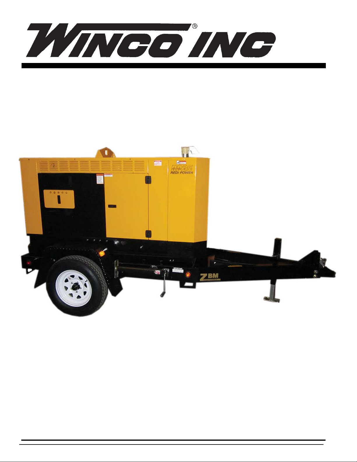
REDI POWER
MOBILE
DIESEL
RP25/C
INSTALLATION AND OPERATION MANUAL
Page 2

SAVE THESE INSTRUCTION
This manual contains important instructions that
should be followed during installation and maintenance of the generator and batteries.
Read and understand all instructions in the manual
before starting and operating the generator set.
USING THIS MANUAL
Congratulations on your choice of a Winco generator set.
You have selected a high-quality, precision-engineered
generator set designed and tested to give you years of
satisfactory portable service.
To get the best performance from your new engine generator set, it is important that you carefully read and follow
the operating instructions in this manual.
Should you experience a problem please follow the
“Things To Check” near the end of this manual. The warranty listed in this manual describes what you can expect
from WINCO should you need service assistance in the
future.
PROPER USE AND INSTALLATION
You must be sure your new engine generator set is:
* Properly serviced before starting
* Operated in a well ventilated area
* Exhaust gases are dispersed safely
* Wired by a qualified electrician
* Operated only for its designed purposes
* Used only by operators who understand its operation
* Properly maintained
COPY YOUR MODEL AND SERIAL NUMBER BELOW FOR FUTURE REFERENCE.
TABLE OF CONTENTS
PRODUCT SAFETY 1
SPECIFICATIONS 2
PREPARATION
UNPACKING 2
OIL REQUIREMENTS 2
FUEL REQUIREMENTS 2
COOLANT REQUIREMENTS 3
BATTERY CONNECTIONS 3
CONTROL PANEL LAYOUT & DESCRIPTION
DSE7310 ENGINE CONTROL 4
FRONT PANEL DESCRIPTION 6
RECEPTACLE AND BREAKERS 7
FULL POWER CONNECTIONS 7
CAM-LOCK CONNECTIONS 8
OPERATIONS
OUTPUT VOATAGE TABLE 9
SELECTING THE CORRECT
VOLTAGE 10
START-UP CHECKLIST 10
ELECTRIC STARTING 10
REMOTE STARTING 11
CONNECTING THE LOADS 10
UNIT STORAGE 12
50 CYCLE OPERATION 12
MAINTENANCE 13
PREVENTIVE MAINTENANCE 11
WIRING DIAGRAMS
DC ELECTRICAL SCHEMATIC 14
GENERATOR WIRING 15
SELECTOR SWITCH WIRING 16
CIRCUIT BREAKER WIRING 17
RECEPTACLE PANEL 17
WARRANTY 18
No other WINCO generator has the same serial number
as yours. It is important that you record the number and
other vital information here, if you should ever need to
contact us on this unit it will help us to respond to your
needs faster.
MODEL____________________________________
SERIAL NUMBER____________________________
PURCHASE DATE____________________________
DEALER___________________________________
Page i
Page 3

GUIDE TO PRODUCT SAFETY
This engine generator set has been designed and
manufactured to insure your personal safety. Improper
use can result in potential deadly hazards, from electrical shock, exhaust gas asphyxiation, or fire. Please read
all safety instructions carefully before installation or use.
Keep these instructions handy for future reference. Take
special note and follow all warnings on the unit and in the
manuals.
************************************************************
CAUTION: Possible Damage to Equipment.
CAUTION notes indicate any condition or practice, which
if not strictly observed or remedied, could result in damage or destruction of the equipment.
************************************************************
************************************************************
WARNING: Personal Danger.
WARNING notes indicate any condition or practice, which
if not strictly observed, could result in personal injury or
possible loss of life.
***********************************************************
ELECTRIC SHOCK - The output voltage present in
1.
this equipment can cause a fatal electric shock. This
equipment must be operated by a responsible person.
A. Do not allow anyone to operate the generator without
proper instruction.
B. Guard against electric shock.
C. Avoid contact with live terminals or receptacles.
D. Use extreme care if operating this unit in rain or snow.
E. Use only three-prong grounded receptacles and extension cords.
F. Be sure the unit is properly grounded to an external
ground rod driven into the earth.
2. FIRE HAZARD - Diesel fuel and other fuels always
present a hazard of possible explosion and/or fire.
A. Do not refuel when the engine is running or hot. Allow
the engine to cool at least two minutes before refueling.
B. Keep fuel containers out of reach of children.
C. Do not smoke or use open flame near the generator
set or fuel tank.
D. Keep a fire extinguisher nearby and know its proper
use. Fire extinguishers rated ABC by NFPA are appropriate.
E. Store fuel only in an approved container, and only in a
well-ventilated area.
3. DEADLY EXHAUST GAS - Exhaust fumes from any
internal combustion engine contain carbon monoxide, an
odorless and deadly gas that must be mixed with fresh
air.
A. Operate only in well ventilated areas.
B. Never operate indoors.
C. Never operate the unit in such a way as to allow exhaust gases to seep back into closed rooms (i.e. through
windows, walls or floors).
4. NOISE HAZARD - Excessive noise is not only tiring,
but continual exposure can lead to loss of hearing.
A. Use hearing protection equipment when working
around this equipment for long periods of time.
B. Always operate with the housing doors closed to reduce the operational noise level.
5. CLEANLINESS - Keep the generator and surrounding
area clean.
A. Remove all grease, ice, snow or materials that create
slippery conditions around the unit.
B. Remove any rags or other material that could create
potential fire hazards.
C. Carefully wipe up any gas or oil spills before starting
the unit.
D. Never allow leaves or other flammable material to
build up around the engine exhaust area.
6. SERVICING EQUIPMENT - All service, including the
installation or replacement of service parts, should be
performed only by a qualified technician.
A. Use only factory approved repair parts.
B. Do not work on this equipment when fatigued.
C. Never remove the protective guards, cover or receptacle panels while the engine is running. Keep hands away
from all moving parts.
D. Never wear neckties or other loose clothing that can
be caught in moving parts while you are servicing or
operating this equipment.
E. Use extreme caution when working on electrical components. High output voltages from this equipment can
cause serious injury or death.
F. When servicing this unit always avoid hot mufflers,
exhaust manifolds, and engine parts. They all can cause
severe burns instantly.
G. Installing and wiring a mobile diesel generator is not a
“do it yourself” project. Consult a qualified, licensed electrician or contractor. The installation must comply with all
national, state, and local codes.
7. LIFTING THE EQUIPMENT - When lifting always
make sure that the area under the equipment is kept
clear.
A. Be certain rigging is designed to lift unit safely.
B. Never attempt to lift the equipment unless you are
certain the lifting device has sufficient capacity.
C. Never allow the equipment to swing while suspended.
D. Be certain the supporting structure is adequate to
handle the load.
8. TOWING THE EQUIPMENT - When towing this equipment always use a vehicle large enough for safe operation.
A. Never tow without the safety chains secured.
B. Always use the proper size hitch ball on the vehicle.
C. Never attempt to tow with a vehicle that does not have
side mirrors installed.
4200-00
Page 1
60706-246
Page 4

SPECIFICATIONS
GENERATOR SPECIFICATIONS
RP25
KILOWATT 20 kW
KILOVOLT-AMPS (.8 PF)25 kVA
AMPERAGE 277/480 VOLT 3 PHASE 30 AMPS*
120/240 VOLT 3 PHASE 60 AMPS*
120/208 VOLT 3 PHASE 69 AMPS*
120/240 VOLT 1 PHASE 70 AMPS**
*Based on .8 power factor
**Single Phase is limited by the circuit breaker to 150
Amps on the full power terminal block - The
addtional amperage is available through receptacles.
Derate 3% per 1000 feet (305 meters) between 300 feet
(90 meters) and 7,500 feet (2,286 meters) above sea
level. Contact the factory for rating data for operation in
altitudes above 7,500 feet (2,286 meters).
For prime power application (24/7) derate all output rating
by 10%
GENERATOR RESISTANCE
RP25
Generator Make Stamford
Generator Model PI144F
Generator Winding #311
Voltage Regulator AS480
Main Stator 0.265 ohms
Main Rotor 0.708 ohms
Exciter Stator 20.3 ohms
Exciter Rotor 0.201 ohms
ENGINE SPECIFICATIONS
TRAILER/HOUSING
RP25
Capacity 3500 lb.
Fuel Capacity 55 Gallons
Axles Single
Hitch Height Adjustable
Tires P225/75R-15
Tire Pressure 35 psi
Sound Attenuated ULTRA QUIET
Housing Housing Standard
PREPARATION
NOTE: This booklet covers the entire unit, EXCEPT
THE ENGINE. See the engine manufacturer’s operator
manual for specific maintenance and care information regarding the engine. Read ALL instructions in the manuals
provided before attempting to operate the generator set.
UNPACKING
When receiving the unit, be sure to inspect it carefully
for freight loss or damage. Check the nameplate to be
sure it is what you ordered (proper kW, voltage, fuel,
etc.). If you have questions, contact your local authorized
dealer. If you see evidence of loss or damage at the time
of delivery, have the driver sign and describe the loss or
damage in the “memo of loss or damage” section on the
freight bill. Then contact the carrier to get instructions on
filing a claim.
When loss or damage is discovered after the equipment
is delivered, but not seen at the time of delivery, it is referred to as “concealed damage.” Separate any damaged
material and contact the carrier for proper procedures to
file a “concealed damage” claim.
RP25/B
Make Isuzu
Model 4LE1
Fuel Consumption Full Load 1.9 gal/hr
1/2 Load .9 gal/hr
Starting System 12 Volt DC
Fuel Diesel
Oil API CF - CH4
SAE 10W30
8.69 Liters
Oil & Filter Replacement 250 HRS
Coolant 50/50 Mix
2.75 Gallons
Battery 12 Volt (Group 24) 650 CCA*
*Battery is not included.
60706-246
Page 2
OIL REQUIREMENTS
This engine was filled at the factory. Before starting
check the oil level and ensure it is full. If not, refill to the
proper level. See engine manual for proper grade of oil.
OIL QUANTITY US Qt. Liters
RP25 9 8.7
FUEL REQUIREMENTS
See your engine operator's manual for complete type and
fuel grade information.
WARNING -NO BIODIESEL
Filling the Fuel Tank
Standard Trailer - The standard trailer is equipped with
a single 45 gallon fuel tank. Use caution when filling the
tank so as not to overflow the tank into the trailer.
4200-00
Page 5

WARNING PERSONAL DANGER
Never refuel a running engine. Always stop the engine
and allow to cool before refueling.
CAUTION – PERSONAL DANGER
NEVER dispose of a battery in a fire. The battery is capable of
exploding.
Never allow the fuel tank to run completely empty, as air
may enter the fuel system making it necessary to bleed
the engine when restarting.
COOLANT REQUIREMENTS
The cooling system of this engine has been filled at the
factory with a 50% water and 50% ethylene-glycol antifreeze and the proper amount of supplemental coolant
additives. This mixture provides engine protection to -37
degrees F.
When replenishing coolant or changing coolant refer to
your Isuzu engine manual for the proper type and mixture
of water, antifreeze and supplemental coolant additives.
WARNING: EQUIPMENT DAMAGE
Failure to properly follow Isuzu requirements for antifreeze and supplemental coolant additives can lead to
permanent damage to your engine cylinder liner walls.
BATTERY CONNECTION INSTRUCTIONS
WARNING! EQUIPMENT DAMAGE
FAILURE TO PUT THE GENERATOR CONTROL
POWER SWITCH IN THE ‘OFF’ POSITION PRIOR TO
CONNECTING THE BATTERY CABLES) MAY RESULT
IN DAMAGE TO THE ECM (SOLID STATE ENGINE
CONTROL MODULE).
INSTALLING THE BATTERY
A customer supplied twelve-volt battery is required to
complete the installation. Installation of the highest CCA
rated battery, within the correct BCI group, will increase
cold weather starting performance. Gel batteries should
not be used with the battery tender installed in the generator enclosure.
MINIMUM
Model Voltage BCI Group CCA Rating
RP25 12 24 650
Installation and servicing of batteries must be performed
or supervised only by personnel knowledgeable of batteries and the required precautions. Keep unauthorized
personnel away from batteries.
DO NOT open or mutilate the battery. Released electrolyte is
known to be harmful to the skin and eyes and to be very toxic.
These engine generator sets are all NEGATIVE ground.
Be very careful not to connect the battery in reverse
polarity, as this may short circuit the battery charging
system on the engine.
CAUTION – A battery presents a risk of electrical shock and
high short circuit current. The following precautions must be
observed when working with batteries:
1. Remove watches, rings and other metal objects.
2. Use tools with insulated handles.
3. Check both the battery cable ends and the battery
posts to be sure they are free of corrosion.
3. Always connect the battery positive cable first and
then connect the battery negative cable. When
removing the battery cables from the battery reverse
the procedure, disconnect the negative cable first and
then the positive cable.
4. Be sure all connections are tight and coat the terminals and cable end with dialectic grease.
WARNING – The electrolyte is a diluted sulfuric acid that is
harmful to the skin and eyes. It is electrically conductive and
corrosive. The following precautions must always be taken:
* Always wear full eye protection and protective
clothing.
* Where electrolyte contacts the skin, wash off
immediately with water.
* If electrolyte contacts the eyes, flush thoroughly and
immediately with water and seek immediate medical
attention.
* Spilled electrolyte is to be washed down with an acid
neutralizing agent. A common practice is to use a
solution of one pound of bicarbonate of soda (baking
soda) to one gallon of water. The bicarbonate of soda
solution is to be added until the evidence of reaction,
foaming, has ceased. The resulting liquid is to be
flushed with water and the area dried.
DANGER – Explosive Fire Risk
* Never smoke when near batteries
* Do not cause a flame or spark in the battery area
* Always discharge static electricity from your body
before touching batteries by first touching a grounded
metal surface.
When installing or replacing batteries, use the proper
group/size starting battery. The battery should be a
Maintenance Free lead acid design. Deep cycle batteries
will not work for this application.
4200-00
Page 3
60706-246
Page 6
SERVICING BATTERIES
Batteries used on these units may over time lose water.
This is especially true if you are using a trickle charger
to maintain your battery. When refilling the battery with
water use only distilled water. Tap water will shorten the
service life of the battery.
Never fill the battery above the fill line. Over filling above
the upper level line may cause the electrolyte to overflow,
resulting in corrosion to the engine or nearby parts. Immediately wash off any spilled electrolyte following the
procedure above..
CAUTION - NEVER ATTEMPT TO JUMP START THIS
ENGINE. If the battery should accidentally become
discharged disconnect the battery cables and recharge
the battery before attempting to start the unit. Boost/jump
starting this unit improperly will result in PERMANENT
DAMAGE TO THE ENGINE CONTROL MODULE (ECM).
crystal display (LCD) with backlighting can be viewed
under a wide range of ambient light and temperature
conditions.
FEATURES
DSE Generator Controllers have the following features:
• Five-key Menu Navigation
• Engine and Generator Protection
• Programmable Analog Engine Senders
• ECU Communications
• Programmable Logic
• Automatic Transfer Switch Control (Mains Failure)
• User Selectable RS232 & RS485 communications
• Multiple configurable inputs & outputs
• Event Log 250 events
• UL/CSA Listed
FUNCTIONS
DSE-7310 Generator Controllers perform the following
functions:
DESCRIPTION AND IDENTIFICATION
1. ENGINE CONTROL MODULE (DSE7310)
The DSE-7310 Automatic Start Control Module provides
integrated engine-genset control, protection, and metering in a single package. Microprocessor based technology allows for exact measurement, set point adjustment,
and timing functions. Front panel controls and indicators
enable quick and simple DSE-7310 operation. Deep Sea
communication software allows units to be easily customized for each application. A wide temperature-range liquid
ENGINE
A
CONTROL
MODULE
DSE-7310
H
Generator Protection and Metering
Generator protection guards against over voltage, under
voltage, under frequency, and over frequency. Over current and phase imbalance protection is available as an
option at the time of manufacture. Each generator protection function has an adjustable pickup and time delay
setting. Metered generator parameters include voltage,
current, real power (watts), apparent power (VA), and
power factor (PF).
K
J
G
60706-246
B
C
Page 4
D
E
F
4200-00
Page 7

Engine Protection and Metering
Engine protection features include oil pressure and coolant temperature monitoring, over crank protection, ECU
specific protection elements, and diagnostic reporting.
Metered engine parameters include, oil pressure, coolant
temperature, battery voltage, speed, fuel level, engine
load, coolant level (from ECU), ECU specific parameters,
and run-time statistics.
D. AUTO – This button places the module into its AUTOMATIC mode. This module will monitor the remote start
input for a relay closure. When the remote start signal is
received it will time out the start delay (5 Seconds) and
then start the engine generator set. When the remote
start signal is lost (relay opened) the module will shut
the engine generator set down after the cool down timer
has time out. The module will return to the AUTOMATIC
mode and await the next start signal.
All metering functions are displayed on the liquid crystal
display. The front panel display begins with the SUMMARY SCREEN. Pressing the Right arrow key will open the
MAIN MENU screen. The MAIN MENU screen consists
of METERING and SETTINGS
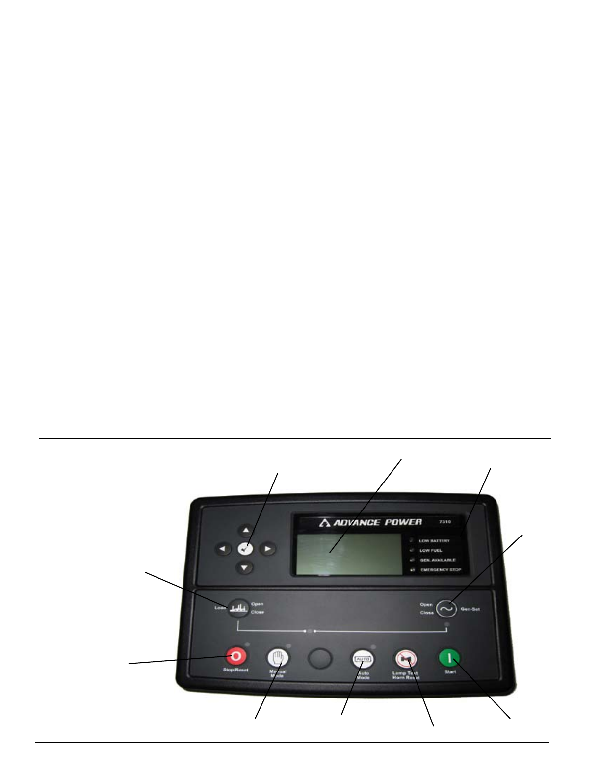
DSE 7310 CONTROLLER LAYOUT
A. MENU NAVIGATION BUTTONS – Left and Right but-
tons select different grouping (i.e. Engine reading Generator reading, etc). Up and Down buttons scroll through
the different reading for each group.
B. STOP/RESET – This button places the module into its
STOP/RESET mode. This will clear any alarm conditions
for which the triggering criteria have been removed. If
the engine is running and this button is pushed the module will shut off the fuel solenoid and the engine will come
to a stop. If a remote start signal is received while this
switch is activated, the unit will not start.
C. MANUAL - This mode allows manual control of the
generator functions. Once in this mode the control module will allow you to start the unit using the START button.
The unit will continue to run until either the STOP/RESET
or AUTO button is pressed. If the unit receives a remote
start signal during manual operation, the generator will
remain running even after the remote start signal has
been lost. You must use the STOP/RESET or AUTO button to stop the unit once you have started it in MANUAL
mode.
**** CAUTION ****
IF THE POWER FAILS WHILE RUNNING IN THE MANUAL MODE THE TRANSFER SWITCH WILL TRANSFER THE LOAD TO THE GENERATOR. TO PREVENT
THIS THE MAINLINE CIRCUIT BREAKER ON THE
GENERATOR MUST BE OPENED.
E. LAMP TEST/HORN RESET - This button silences
the audible alarm if it is sounding and illuminates all of
the LEDs as a lamp test feature.
F. START – This button is active only in the MANUAL
or mode. Pressing this button in the MANUAL mode will
start the engine locally for testing. The engine will continue to run until either the STOP/RESET or the AUTO
button is pressed.
G. CLOSE GEN-SET – NOT USED IN THIS APPLICATION
H. OPEN GEN-SET – NOT USED IN THIS APPLICATION
J. SYSTEM INFORMATION LIGHTS – These lights indicate the following conditions.
1. Low Battery
2. Low Fuel
3. Generator Available
4. Emergency Stop.
K. LIQUID CRYSTAL DISPLAY (LCD) -A wide temperature-range display with backlighting can be viewed under
a wide range of ambient light and temperature conditions.
All engine and generator reading are displayed here,
including fault codes.
NOTE: STOP/RESET, MANUAL mode and AUTO mode
buttons all have indicator lamps next to them to tell you
what mode you are in. Pressing buttons out of sequence
will cause the engine not to do what you may think it
should be doing. See button operation sequencing
above.
4200-00
Page 5
60706-246
Page 8

FRONT PANEL LAYOUT
2. FRONT PANEL LAYOUT
A - Selector Switch Safety Release. This safety button
must be depressed before you can change the selector
switch. Depressing this will also kill the engine, this is to
ensure the unit is not running when the selector switch is
changed.
B - Voltage Selector Switch. This heavy duty four position switch allows the operator to quickly and safely reconnect the 12 lead generator to any one of four output
voltages. Once the output voltage is selected, the switch
will lock to prevent it from accidentally being changed
during operation. (See "A" above)
C - AC Control Fuses (3 each). These 2 amp fuses
limit the AC input into the DSE-7310 controller preventing it from being damaged.
(Replacement Fuse 2 Amp ATO-ATC)
D - DSE7310 Fuse. This 3 amp DC fuse protects the
DSE-7310 printed circuit board.
(Replacement Fuse 3 Amp ATO-ATC)
E - DC Control Circuit Fuse. The 10 amp DC Circuit
Fuse protects the 12 volt circuits and engine wiring harness against faults in wiring or control equipment. The
fuse also prevents a discharge of the battery due to a
circuit fault. (Replacement Fuse 10 Amp ATO-ATC)
F - Generator Control Power Switch. This switch
disconnects all power to the DSE-7310 Engine Control.
This switch should be turn off anytime the unit is going
to be stored longer than over night with out the battery
charger plugged in. Storing the unit without the power
switch turned off will cause the battery to drain as the
DSE-7310 is powered up. This switch is bypassed when
the unit is running to prevent the controller from being
shutoff with the engine running.
G - USB Port. This port is used to program the DSE7310 Controller from a computer using the DEEP SEA
Software. If needed the DEEP SEA software can be
down loaded for the their web site.
(www.deepseaplc.com)
H - DSE-7310 Generator Control. See Explanation on
page 4.
J -Emergency Stop Switch (3)- When depressed
this switch will disconnect all the 12 volt power to the
DSE-7310 shutting the engine down. The lamp in the
emergency stop switch will light up when the switch is
depressed showing that the power to the panel has been
disconnected.
K - Voltage Adjust Rheostat. Controls the output voltage
of the generator by varying voltage regulators reference
voltage. This trim pot is used to adjust the voltage after
you switch between the different voltages on the Selector
Switch. A wide range of voltages are available with 4 position selector switch and rheostat.
60706-246
Page 6
4200-00
Page 9

RECEPTACLES
and CIRCUIT
BREAKERS
3. RECEPTACLES and CIRCUIT
BREAKERS
NOTICE - CLASS 1 WIRING METHODS ARE TO BE
USED FOR ALL FIELD WIRING CONNECTIONS TO
TERMINALS OF A CLASS 2 CIRCUIT. ALL WIRING
MUST BE DONE IN ACCORDANCE WITH
NATIONAL ELECTRIC CODE NFPA 70
A - 208/240 VOLT MAINLINE CIRCUIT BREAKER. This
is the low voltage mainline circuit breaker feeding the full
output terminal block (Ref E) below. This circuit breaker
is used when the selector switch in the 120/208 volt three
phase120/240 volt three phase or 120/240 volt single
phase switch position.
B - 480 VOLT MAINLINE CIRCUIT BREAKER. This is
the high voltage mainline circuit breaker feeding the full
output terminal block (Ref E) below. This circuit breaker
is used when the selector switch is in the 277/480 volt
three phase position.
C - CIRCUIT BREAKER LOCKING BAR. Select and
turn on either the high voltage breaker (480 V) or the low
voltage breaker (208 or 240 Volt) depending on which position you have the selector switch in. This bar prevents
both breakers from being turned on at the same time
D - REMOTE START/E-STOP TERMINAL BLOCK. This
terminal block provides the customer two different connections. Torque Screws to 9.6 in. lb. using 14 to 16
awg copper wire with lugs.
4200-00
Page 7
1. Emergency stop connection for installing a re-
mote emergency stop switch. This emergency stop
switch connection point must be closed during normal
operation, this is done at the factory by installing a
jumper lead between the two connection points. If
you have an application (i.e.. gas station) that requires a remote stop switch be installed, remove the
jumper and install a normally closed emergency stop
switch between the two terminals. When the emergency stop switch is opened the generator will immediately shut down, requiring the switch to be reclosed
before the generator can be restarted.
2. Remote start contact connections for starting the
unit from a remote location. This can be either
an automatic transfer switch or just a remote switch
in a job trailer. This feature requires a relay closure
between the two connections on the terminal block to
put the unit into an auto-start mode. The Auto mode
has both a start delay and a cooldown delay built into
the DSE-7310.
E - FULL POWER OUTPUT TERMINAL BLOCK. The
full power terminal block is capable of handling full
generator output at any of the selected voltages. Be very
careful when using 240 volt three phase that you properly account for the wild leg (208 Volt) coming from the
generator. This unit has it in the L2 position. For single
phase 120/240 connect to L1 and L3, the third leg L2 is
not powered or used. Lugs will handle up to 2/0 wire.
Torque lugs to 150 in. lbs. using #1 & #2 wire and 180
in. lbs. for 1/0 & 2/0 wire.
60706-246
Page 10

F - NEUTRAL TERMINAL BLOCK. This is the neutral
connection point for the customers full power output
connections. This terminal block also has the neutral to
ground bond attached. If you need to operate an isolated
ground system this jumper must be removed. Generally
this is only required when the generator is being used as
backup or being wired into an existing wiring system that
already has one neutral to ground bond in it. Lugs will
handle up to 2/0 wire. Torque lugs to 150 in. lbs. using #1 & #2 wire and 180 in. lbs. for 1/0 & 2/0 wire.
G - GROUND TERMINAL BLOCK. This is the ground
connection point for the customer's full power output
connections. This terminal block also has the neutral
to ground bond attached to it. If you need to operate an
isolated ground system this jumper must be removed.
Generally this is only required when the generator is being used as backup or being wired into an existing wiring
system that already has one neutral to ground bond in it.
Lugs will handle up to 2/0 wire. Torque lugs to 150
in. lbs. using #1 & #2 wire and 180 in. lbs. for 1/0 &
2/0 wire.
H - WIRE ENTRANCE HOLES. These hole have been
specifically provided for you to route your full power
leads through to the output lugs. The routing holes were
provided to insure that no small child or curious adult can
reach inside and come into contact with the main output
lugs with the unit running.
J - 120 VOLT 20 AMP 3 WIRE RECESSED SHORE
POWER PLUG, NEMA Spec 5-20. This panel mounted
plug is designed to plug directly in a standard 20 amp
receptacle on a extension cord. The plug when connected will provide power to the block heater and the
battery trickle charger mounted inside the generator
enclosure. This can be used when the set is used in a
standby application to keep the engine warm and the
battery charged or in your rental yard to keep the battery
charged up. This receptacle is to be powered by a GFCI
circuit and installed in accordance with the United States
National Electric Code.
tribution box. Each receptacle is protected by a two pole
50 amp circuit breaker mounted just above it.
THIS RECEPTACLE UTILIZES A HUBBELL PLUG PART
NUMBER “CS 6365”.
N - 250 VOLT 50 AMP CIRCUIT BREAKERS. These
circuit breakers protect the two 50 amp twistlock receptacles (Ref M) mounted in the panel below.
P - DOOR SAFETY SWITCH. This safety switch is connected to the DSE-7310 engine control and will shut the
unit down any time door is opened with the unit running.
This prevents someone from accidently contacting the
main power connection with the unit running. This unit
will not start if the door is not closed and latched.
DANGER: PERSONAL INJURY
This unit may start as soon as the door is closed if the
engine control happen to be the correct mode. Do not
use the switch on this door to shutdown a unit to connect
to the full load terminal block , this is a safety switch only.
4. CAM-LOCK CONNECTIONS
This unit is equipped with Cam-Lock connectors, located
behind the rear right hand door panel. These Cam-Lock
are connected to the full load terminal blocks and a capable of providing full generator output in all voltage configurations. The mating connectors are model CL2FB,
which are available with different wire size capabilities.
K - TWO - 120 VOLT 20 AMP GROUND FAULT
INTERRUPTER DUPLEX. These duplex receptacles are
protected by 20 Amp circuit breakers mounted just above
the duplexes. With the “T” slot design both 15 and 20
amp 120 volt cords can be plugged in.
L - 120 VOLT 20 AMP CIRCUIT BREAKERS. These
two push button 20 amp circuit breakers protect the two
GFCI receptacles (Ref K) mounted below. If you are not
able to reset these breakers, check the load plugged into
the GFCI receptacle or the receptacle itself for a fault.
M - TWO 120/240 VOLT 50 AMP 4 WIRE TWISTLOCK.
These receptacles are rated for dual voltage, 120 or
240 volt use. It is a four wire receptacle, with a center
grounding pin. Four wire drop cords plugged into this
receptacle may be split into 120 volt receptacles at a dis-
60706-246
Page 8
4200-00
Page 11

The table below show the voltages at the terminal lug as well as the receptacles
for all four voltage patterns available through the selector switch.
VOLTAGE SELECTOR SWITCH
POSITION
TERMINALS MINIMUM
VOLTAGE
NORMAL
VOLTAGE
MAXIMUM
VOLTAGE
120/240 SINGLE PHASE
LINE TO LINE L1 TO L3 220 240 260
120/240 VOLT RECEPTACLES 110/220 120/240 130/260
LINE TO NEUTRAL L1 TO N 110 120 130
L2 TO N -0- -0- -0-
L3 TO N 110 120 130
120 VOLT RECEPTACLES 110 120 130
120/208 THREE PHASE
LINE TO LINE ALL 200 208 220
120/240 VOLT RECEPTACLES 110/200 120/208 127/220
LINE TO NEUTRAL ALL 115 120 127
120 VOLT RECEPTACLES
ALL 115 120 127
G3 TO N 115 120 127
120/240 THREE PHASE
LINE TO LINE ALL 220 240 260
120/240 VOLT RECEPTACLES 110/220 120/240 130/260
LINE TO NEUTRAL
USE CAUTION THIS CONFIGURATION HAS A HIGH VOLTAGE
LEG
G1 TO N 110 120 130
HIGH VOLTAGE LEG G2 TO N 191 208 225
G3 TO N 110 120 130
120 VOLT RECETPACLES 110 120 130
277/480 THREE PHASE
LINE TO LINE ALL 416 460 480
120/240 VOLT RECEPTACLE
NONE NONE NONE
LINE TO NEUTRAL ALL 240 265 277
120 VOLT RECETPACLE
WARNING - POTENTIAL EQUIPMENT DAMAGE
THE 120/240 VOLT THREE PHASE POSITION HAS A WILD LEG THAT PRODUCES 208 VOLTS LINE TO
NEUTRAL ON G2. BE SURE WHEN CONNECTING TO YOUR PANEL OR LOAD THAT YOU MATCH THE
WILD PHASE ON THE GENERATOR TO THE WILD PHASE IN YOUR PANEL OR LOAD. FAILURE TO DO
SO WILL RESULT IN 12O VOLT DEVICES RECEIVING 208 VOLTS. YOU MUST ALSO MATCH YOUR
ROTATION.
4200-00
Page 9
NONE NONE NONE
60706-246
Page 12

OPERATING THE UNIT
A. SETTING THE JACKS
1. Move the two rear jacks from the transport position to
the run position.
2. Rotate the front jack from the transport position to the
run position.
3. Level the unit using the three jacks before starting
the unit up.
7. Fuel tank filled with the proper grade of diesel
fuel.
8. Check the fan belt for tightness and excessive
wear.
9. Check hoses and clamps for leakage.
10. Check the air cleaner indicator. Service only
when indicated. Do not over-service.
11. Clean out dust cup on the air cleaner.
D. ELECTRIC STARTING (Normal portable use)
WARNING - POTENTIAL EQUIPMENT DAMAGE
Be sure to return the jacks to the transport position before trying to move the unit. If you don't the jacks maybe
damaged, rendering them useless.
B. SELECTING THE CORRECT VOLTAGE
A variety of voltages are available from the four position
selector switch. The four basic connection patterns are,
Delta (120/240), Low or Parallel WYE (120/208), High
WYE (277/480) and Single phase 120/240. See page 9
for the different voltages available in each of the voltage
configurations.
Before starting this unit be sure you have the selector
switch set for the right voltage. You must depress the
safety switch below the selector switch to change the position of the voltage selector switch. If the unit is running
depressing this switch will kill the engine generator set.
If you have any doubts as to the voltage in your area
compare your incoming power or load name plates to the
voltage table below.
CIRCUIT BREAKER SELECTION
After you have selected the correct voltage for your application and locked the selector switch, do the same
with the main line circuit breakers. The left hand circuit
breaker is used for all voltage selections except 480 volt
in which case you would use the right hand breaker.
Failure to use the correct breaker will either give you no
breaker protection at all or cause the breaker to trip early.
C. STARTUP CHECKLIST
CAUTION: EQUIPMENT DAMAGE
DO NOT ATTEMPT TO JUMP/BOOST START THIS
UNIT. TO DO SO MAY DAMAGE THE ELECTRONIC
MICROPROCESSOR IN THE ENGINE CONTROL. RECHARGE THE BATTERY WITH A BATTERY CHARGER.
1. Select the desired voltage on the voltage selector
switch.
2. Turn off both main line circuit breakers.
3. Depress the MANUAL mode button on the control
panel. The small LED light next to it should come on.
4. Press the START button- The DSE-7310 will send a
signal to the glow plug solenoid on the engine. Preheating the engine for about 10 seconds at the end of
that time it will engage the fuel rack solenoid and the
starter. This will start the cranking cycle (10 seconds
on and 10 seconds off).
NOTE: There is no start delay in this mode of operation.
If the engine fails to start during this cranking period the
starter motor is disengaged and goes into a rest mode
after which a second attempt is made to start the engine.
Should this sequence continue through 3 cranking cycles
the start sequence will be stopped and the display will
show "FAILED TO START".
All engine functions are controlled by the DSE-7310
controller. Once the unit is running the control will display
the engine information as well as the generator information by scrolling down through the controller. See page 5
for instructions on moving through the DSE-7310 display
screens.
Before initial start up and each subsequent start complete
the following checklist:
1. Check oil level, refill with proper grade oil.
2. Check coolant level, refill with proper mixture of
coolant. See engine manual.
3. Check for loose bolts or hardware.
4. Check tire pressure. (35 psi)
5. Trailer level to within 15 degrees.
6. Battery securely fastened, connection clean and
tight, and proper fluid level.
60706-246
Page 10
The AC output readings displayed on the DSE-7310 are
collected through the AC interface harness wired in the
generator control box. Any shutdowns related to the AC
output are a function of the controller are based on information collected in the DSE-7310 via this AC harness.
5. After the engine is running at proper speed, adjust
the voltage to the desired level using the external
voltage trim rheostat.
6. Turn on the proper main line breaker (either high
or low voltage) and padlock the lock bar to prevent the
incorrect breaker from being turned on.
4200-00
Page 13

WARNING: EQUIPMENT DAMAGE
NEVER APPLY A LOAD TO THE GENERATOR UNTIL
YOU HAVE FIRST CHECKED THE VOLTAGE AT THE
TERMINAL BLOCKS OR THE CAM-LOCKS.
7. With the engine running smoothly check the no load
voltage and frequency on the digital display. The
voltage should be 208/240/480 AC depending on
which model you have and a frequency of 59.5
to 60.5 hertz (Hz).
If you have the proper voltage at the generator the next
step is to check the voltage at the customer connection points, wither the terminal block or the Cam-Lock,
that you intend to use. The voltage between the L1, L2
and the L3 terminals should be the same as it was on
the generator front panel. The voltage should also be
checked between the hot terminals (L1, L2 and L3) and
the N to be certain of a balanced voltage output and a
solid neutral connection. See the voltage table on page 9
for proper voltage reading in each selector switch position. WHEN USING THE 120/240 VOLT THREE PHASE
(DELTA) SYSTEMS BE SURE YOU KNOW WHERE
THE HIGH VOLTAGE "WILD" LEG IS. IT MUST BE IN
THE SAME LOCATION ON THE GENERATOR SIDE AS
IT IS ON THE LOAD SIDE.
** Notice **
If for any reason during the check out procedure the voltage and frequency are not correct, depress the STOP/
RESET button and correct the problem before proceeding.
8. Stopping - There are two ways to stop the unit when
t is in the manual mode. Pressing the STOP/RESET
button will stop the unit immediately. Pressing the
AUTO mode button will stop the unit but only after
the cool down timers have timed out and there Is no
remote start signal being sent to the unit.
E. REMOTE STARTING AND CONNECTION
(Standby applications)
1. Complete the manual starting procedure above to
ensure the system is set up properly.
WARNING: EQUIPMENT DAMAGE
THE REMOTE “SIGNAL” MUST BE A “DRY” (NONPOWERED) CONTACT CLOSURE. USING A POWER
CONTACT WILL CAUSE PERMANENT DAMAGE TO
THE ENGINE CONTROL MODULE.
5. For most installations 16-gauge wire is sufficient
to handle the control signal. On extremely long runs
increase wire size to minimize voltage drop.
6. Locate the neutral and full power output load connection terminal on the generator.
7. Locate and identify the “neutral” and “generator” connections in the automatic transfer switch.
8. Connect the load block to the transfer switch using
the proper wire sizes. Refer to the National Electric
Code Handbook (NFPA 70) for proper wire type and
sizing. Use Table 310-16 for wiring run through conduit and table 310-17 for free air wiring.
Use extreme caution when installing the delta voltage
pattern. One power leg of this 3 phase pattern produces 208 volts measured from line to neutral. Be sure
to match the location of the generator wild leg to the
location of the wild leg on the incoming power service.
Failure to do so will cause equipment damage to any 120
volt load incorrectly connected to this line.
9. Connect the neutral to the transfer switch using the
same wire size.
10. For isolated neutral operation remove the jumper
wire between the ground lug and neutral connection block. Then route a ground lead back to system
ground.
11. Ground the Mobile Diesel Generator set using an 8 ft.
copper ground rod or other approved grounding system. Connect #4 Awg Copper cable from the ground
lug on the generator to the ground rod.
12. Depress the "RUN" button on the RP25 control panel
to start the generator set.
2. Ensure the engine control is in the “off” position during installation of the remote start connections.
3. Locate the remote start terminal block. This terminal
block is located next to the full power connections,
behind the access door on the control panel.
4. Locate the remote start terminals in your remote
automatic transfer switch (ATS). The ATS terminal
block and wire numbers will vary with each ATS
manufacturer. The RP25 requires a contact closure
for start.
4200-00
Page 11
13. Check the voltage at the transfer switch. Verify that it
matches the incoming power line voltage line-to-line
and line-to-neutral on each leg.
14. Check the three phase rotation pattern. Ensure that
you have the same rotation, with both the generator
and the normal power source.
15. Depress the “STOP” button on the front of the
engine control. Let the unit stop and then depress
the “AUTO” button. The unit is now in AUTOMATIC
mode. Also be sure the "AUTO" light is lighted on
the control, this light tells you it is in automatic mode.
See control panel layout for additional information.
60706-246
Page 14

16. If the transfer switch has a test button use it to test
the complete system. The unit should start up and
the transfer switch should transfer the load to the
generator.
17. Compare the amperage reading from each leg on the
generator and ensure that none of the legs is exceeding the nameplate rating on the generator.
4. GROUNDING THE UNIT - To comply with current
safety standards this generator set must be properly
grounded. Ground the Mobile Diesel Generator set
by driving an 8 ft. copper ground rod into the earth.
Then connect a #4 AWG ground cable from the
grounding lug on the generator to the ground rod.
G. UNIT STORAGE
18. Upon completion of the test, leave all control mode
switches in the “AUTO” position.
19. The system is now ready to start and power the loads
should the power fail.
F. CONNECTING THE LOADS FOR STAND ALONE
OPERATION
WARNING -ALL WIRING MUST BE DONE IN ACCORDANCE WITH NATIONAL ELECTRIC CODE NFPA 70
There are three ways the loads may be connected to
Mobile Diesel Generator.
1. FRONT PANEL - A variety of receptacles have been
provided for your convenience on the front panel.
The 120 volt receptacles are powered when the voltage selector switch is in the 120/240 single and three
phase and 120/208 three phase volt position. The
240 volt receptacles are only usable in the 120/240
volt single and three phase position. In the 120/208
volt three phase position the 240 volt receptacles
have only 208 volts at them. See table on page 9 for
voltage outputs.
Certain precautions must be taken if a Mobile Diesel
Generator set is to be stored for a long period of time.
The unit must be stored in a dry location to prevent the
generator winding from drawing moisture. The unit should
also be thoroughly cleaned prior to storage.
For engine storage procedures consult your local Isuzu
engine dealer. There are procedures that must be followed in order to prevent engine damage, i.e. cylinder
rust and injector deterioration.
50 CYCLE (HZ) OPERATION
With a couple of minor changes these Mobile Diesel
Generators are capable of producing 50 Hz power. Two
changes must be made:
A. The engine must be reduced to 1500 RPM governed
speed. Consult your local Isuzu Service Center for the
proper procedure for reducing the engine speed and setting up the governor to operate at 1500 RPM.
B. The automatic volt/hertz regulator must also be reset
to operate at 50 HZ instead of the standard 60 HZ. Refer
to the Stamford generator manual for instructions.
2. FULL POWER LOAD CONNECTION TERMINAL
BLOCK - For remote connections and connecting
load distribution boxes, heavy duty terminal blocks
have been provided. These terminal blocks are
located on the rear of the unit just below the Engine
Contol. The neutral and ground are connected together at this panel. For use with an isolated neutral,
remove the jumper strap between the neutral connection block and the ground lug. This will isolate
the neutral from the ground and allow you single
point grounding at a distribution panel. When using
these terminal blocks be sure to use wire rated large
enough to carry your full load or the full rated load of
the generator.
3. FULL POWER CAM-LOCK CONNECTIONS - For
ease of connecting and disconnecting loads these
units have been equipped with Cam-Locks located
behind the right hand rear door. See page 8 The
same instructions for connection #2 applies. If you
need to run a isolated neutral system, the jumper
between the neutral and ground must be removed at
the terminal block.
MAINTENANCE
The ultimate aim of a preventive maintenance program is
to maintain the equipment in optimum condition, for the
maximum amount of time during it's useful life. The detection of faults before they develop into major problems
will decrease downtime. A regular schedule of cleaning
and inspection will help assure trouble-free operation.
Personnel responsible for maintenance should set up a
schedule for inspection, and cleaning at intervals calculated to keep the equipment in good condition. In making
up a schedule, keep the following in mind:
A. New equipment must be carefully monitored until
extended operation has demonstrated that it is performing satisfactorily.
B. Old equipment requires more frequent inspection
(and possibly servicing) than similar equipment that has
lower hours
C. Time spent in cleaning, inspecting and correcting
minor defects before they become major troubles saves
time in overhaul and repair.
60706-246
Page 12
4200-00
Page 15

PREVENTIVE MAINTENANCE
** Inspect for any fluid leaks
A. Daily Maintenance Checklist
** Oil level is between the “L” low mark and the “H” high
mark on the dipstick
** Fuel tank full of proper grade of diesel fuel
** Water and sediment drained from water separator
** Radiator filled with the proper coolant mixture
** Check air cleaner service indicator. Change the filter
element when the red indicator flag is at the raised position
DC ELECTRICAL SCHEMATIC LEGEND
** Look for any loose or damaged parts
** Check belts for cracks or frays
** Check trailer hitch and safety chains for fitness
** Check tires for proper pressure
** Check battery for proper fluid level
** Check the generator control panel for loose or damaged parts
** Check the unit for general appearance and cleanliness
4200-00
Page 13
60706-246
Page 16

DC ELECTRICAL SCHEMATIC
60706-246
Page 14
TO GENERATOR
CONNECTOR
AC INTERFACE
4200-00
Page 17

AC INTERFACE
CONNECTOR
TO DSE-7310
GENERATOR WIRING
VOLTAGE
REGULATOR
4200-00
Page 15
60706-246
Page 18

VOLTAGE SELECTOR SWITCH WIRING
60706-246
Page 16
4200-00
Page 19

CIRCUIT BREAKER/FULL POWER
TERMINAL BLOCK WIRING
4200-00
Page 17
60706-246
Page 20

12 MONTH LIMITED WARRANTY
WINCO, Incorporated warrants to the original purchaser for 12 months or 1000 hours which ever
occurs first, that goods manufactured or supplied by it will be free from defects in workmanship
and material, provided such goods are installed, operated and maintained in accordance with
WINCO written instructions.
WINCO’s sole liability, and Purchaser’s sole remedy for a failure under this warranty, shall be limited to the repair of the product. At WINCO’s option, material found to be defective in material or
workmanship under normal use and service will be repaired or replaced. For warranty service, return the product within 12 months or 1000 hours which ever occurs first from the date of purchase,
transportation charges prepaid, to your nearest WINCO Authorized Service Center or to WINCO,
Inc. at Le Center Minnesota.
THERE IS NO OTHER EXPRESS WARRANTY.
To the extent permitted by law, any and all warranties, including those of merchantability and fitness for a particular purpose, are limited to 12 months or 1000 hours which ever occurs first, from
date of purchase. In no event is WINCO liable for incidental or consequential damages.
Note: Some states do not allow limitation on the duration of implied warranty and some states do
not allow the exclusion or limitation of incidental or consequential damages, so the above limitations may not apply in every instance. This warranty gives you specific legal rights which may
vary from state to state.
WINCO reserves the right to change or improve its products without incurring any obligations to
make such changes or improvement on products purchased previously.
EXCLUSIONS:
WINCO does not warrant Engines. Engines are covered exclusively by the warranties of their respective
manufacturers, see enclosed warranties.
WINCO does not warrant Batteries, or Other Component Parts that are warranted by their respective
manufacturers.
WINCO does not warrant modifications or alterations which were not made by WINCO, Inc.
WINCO does not warrant products which have been subjected to misuse and/or negligence or
have been involved in an accident.
225 South Cordova
Le Center MN 56057
60706-246 4200-00
507-357-6831
www.wincogen.com
 Loading...