

Page 1
INSTALLATION INSTRUCTIONS
2-WHEEL PTO TRAILER
MODELS: 25 THRU 75 KW
1
4
2
3
5
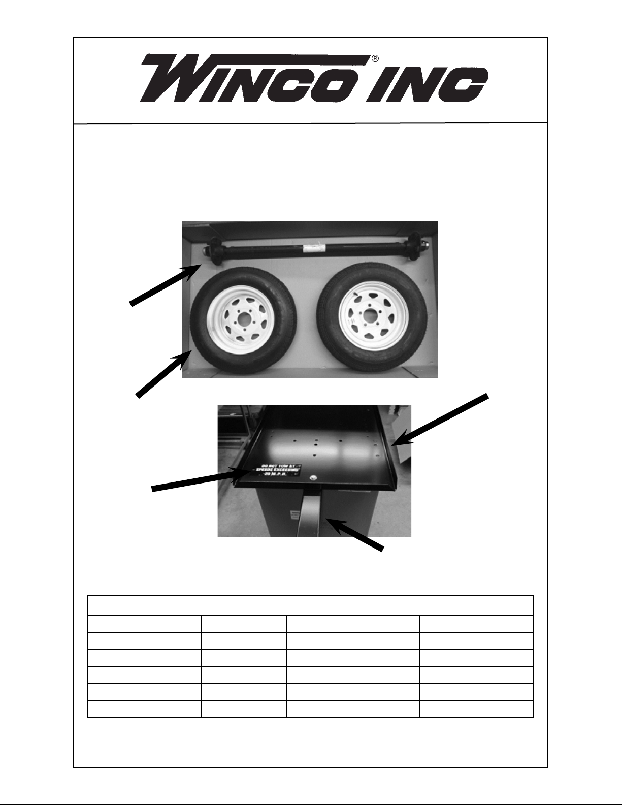
COMPONENT LIST
REF. # PART # DESCRIPTION QTY.
1 97104-000 Axle 1
2 97105-000 Wheel 2
3 64006-000 Decal 1
4 97102-000 Base Pan 1
5 97101-000 Tongue Extension Bar 1
113150-00 97100-101
Page 2
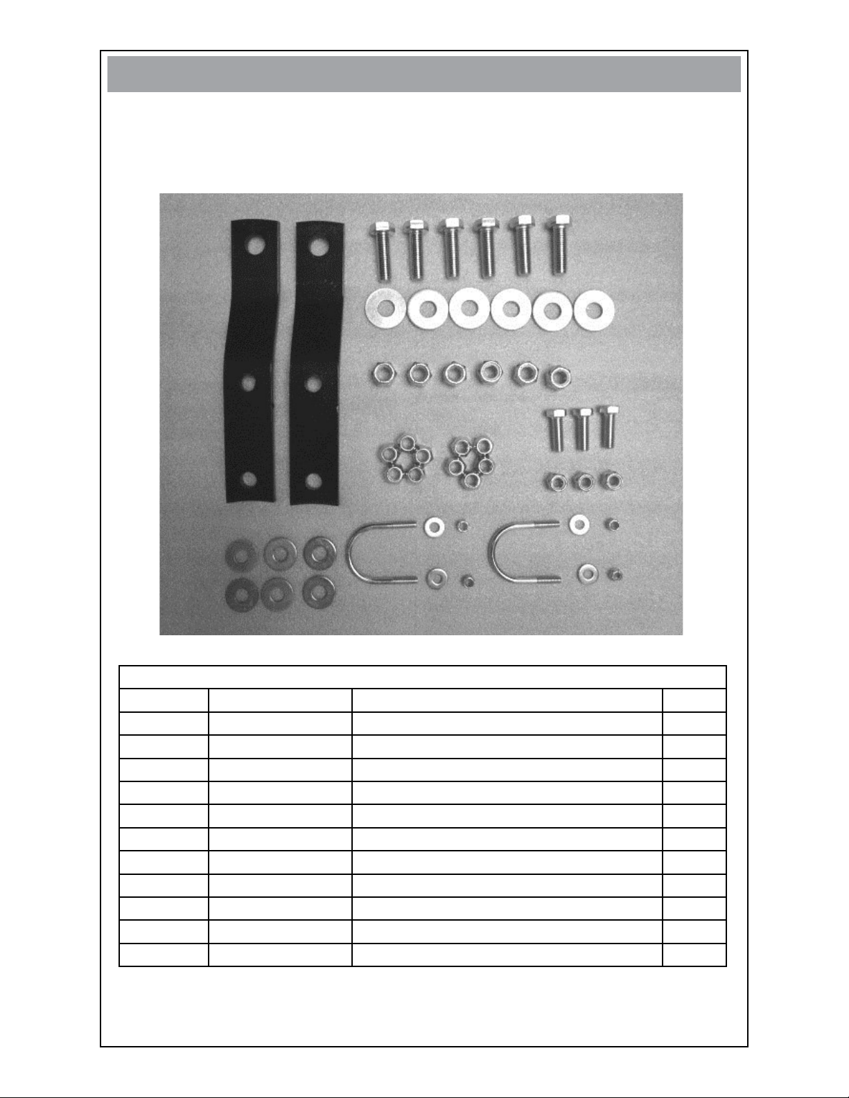
STEP 1
Open hardware bag and account for all fasteners and components.
•
FASTENERS & MISC. COMPONENTS
(not shown in actual size)
7
8
6
10
9
11
13
16
14
15
12
FASTENER & COMPONENT LIST
REF # PART # DESCRIPTION QTY
6 252101030 Tongue End 2
7 91083-004 5/8”-11 X 2” Bolt 6
8 515-000 5/8” Flat Washer 6
9 95468-000 5/8” Nylok Nut 6
10
11 57580-000 1/2”-13 X 1 1/2” Bolt 3
12 21867-000 9/16” Flat Washer
13
14 252003010
15
16 47136-000 5/16”-18 Nylock Nut
252003060 1/2”-20 Lug Nut 10
6
92242-000 1/2”-13 Nylok Nut 3
U-Bolt 2
526-000 5/16” Flat Washer 4
4
213150-00 97100-101
Page 3
STEP 2
A
A
E
E
E
E
B
C
D
B
C
D
BACK
FRONT
X
Determine which model generator you are mounting to the trailer.
•
Identify the corresponding holes you will be using to mount the generator. This will
•
determine which three holes to use when attaching the Tongue.
MODEL BACK HOLES FRONT HOLES
35PTOC A B
45PTOC A B
50PTOC A C
75PTOC A D
25PTOC E E
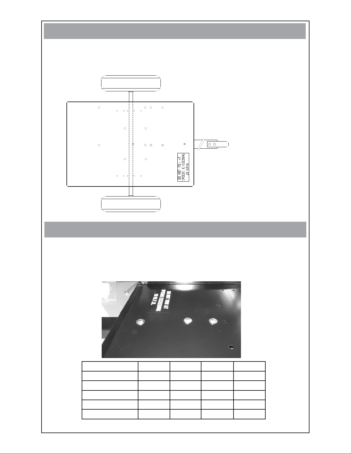
STEP 3
The picture below represents the bolt holes used to mount the tongue for models
•
25PTOC, 35PTOC and 45PTOC. Note that hole B is left open for the generator to
be mounted. See the table below for your model.
Hole X is used for all models of generators.
•
•
Attach tongue to the base pan using hardware (ref. 11, two 12’s & 13).
X
D
MODEL X B C D
25PTOC Yes No Yes Yes
35PTOC Yes No Yes Yes
45PTOC Yes No Yes Yes
50PTOC Yes Yes No Yes
75PTOC Yes No Yes No
C B
313150-00 97100-101
Page 4

STEP 4
A
A
E
E
E
E
B
C
D
B
C
D
X
Attach tongue ends (ref. 6) to tongue using hardware (ref. 7, 8, 9). The washers
•
(ref. 8) are not shown in this picture. They were added and go under the head of
the bolt (ref. 7).
6
7, 8, 9
STEP 5
Determine which holes to use to attach the axle to the base pan.•
Use the axle location below for model: 25PTOC.•
413150-00 97100-101
Page 5

A
A
E
E
E
E
B
C
D
B
C
D
X
Use the axle location below for models: 35PTOC, 45PTOC, 50PTOC & 75PTOC.•
STEP 6
Flip the base pan and tongue assembly over and attach the axle to the base pan
•
loose using hardware (ref. 14, 15, 16). Snug up the nuts on the u-bolts keeping
the u-bolts even. Do not tighten.
Adust the axle so it is evenly spaced on the base pan. It should measure approxi-
•
matly 7 5/8” from the edge of the base pan to the outer edge of the wheel hub on
both sides.
Tighten the u-bolts securely to the base pan.
•
Flip the trailer assembly over to attach the wheels.
•
513150-00 97100-101
Page 6

STEP 7
Place the wheels on the hubs with the air-fill nozzle facing out and attach with lugs
•
(ref. 10). Make sure that the lugs have the flat side facing out.
Tighten all lugs securely.
•
613150-00 97100-101
Page 7

STEP 8
Remove the the nuts from the hold-down bolts (A).
•
Lift the generator off the shipping skid using a hoist or a handy-man jack (B).
•
Set generator on the trailer and align the generator feet holes with the proper
•
mounting holes on the base pan.
A
B
Attach the generator to the base pan using hardware (ref. 7, 8, 9).•
WINCO INC.
225 S. CORDOVA AVE.
LE CENTER, MN 56057
(507) 357-6821
SERVICE DEPT.
(507) 357-6831
STEP 9
713150-00 97100-101
 Loading...