

Page 1
PACKAGE
STANDBY
SYSTEMS
PSS50LS/C
PSS75LS/A
INSTALLATION AND
OPERATIONS MANUAL
for UNITS EQUIPPED
WTH BASLER DIGITAL
GENSET CONTROLS
Engine Generator Set
225 SOUTH CORDOVA AVE
LE CENTER MN 56057
507-357-6831
Page 2

Read and understand all instructions in
the manual before starting and operating the
generator set.
USING THIS MANUAL
Congratulations on your choice of a Winco generator
set. You have selected a high-quality, precision-engineered
generator set designed and tested to give you years of
satisfactory standby service.
To get the best performance from your new engine
generator set, it is important that you carefully read and
follow the operating instructions in this manual.
Should you experience a problem please follow the
“Things To Check” near the end of this manual. The warranty
listed in this manual describes what you can expect from
WINCO should you need service assistance in the future
COPY YOUR MODEL AND SERIAL NUMBER
HERE
No other WINCO generator has the same serial number as
yours. It is important that you record the number and other
vital information here. If you should ever need to contact us
on this unit it will help us to respond to your needs faster.
MODEL_____________________________________
SERIAL NUMBER____________________________
PURCHASE DATE____________________________
DEALER____________________________________
TABLE OF CONTENTS
INTRODUCTION i
GUIDE TO PRODUCT SAFETY 1
BASIC INFORMATION 2
Description 2
Specification Table 3
PREPARING THE UNIT 4
Unpacking the unit 4
ENGINE GENERATOR INSTALLATION 4
Installation 4
Fuel Line Installation 5
Fuel Pressure Tables 5
LP Liquid Withdrawal 6
Lubrication 6
Coolant 6
Battery Installation 6
Battery Charger/Bloack Heater Wiring 6
TRANSFER SWITCH INSTALLATION (NON-UL) 6
AC Electrical Connections 7
DC Electrical Connections 8
TRANSFER SWITCH INSTALLATION (UL) 8
AC Electrical Connections 8
DC Electrical Connections 8
INITIAL START-UP 9
EXERCISER CLOCK 10
TROUBLESHOOTING INFORMATION 10
LP/NG CONVERSION 11
AC WIRING - THREE PHASE
277/480 Volt 12
120/208 Volt 12
120/240 Volt 13
AC WIRING - SINGLE PHASE
120/240 Volt 13
VOLTAGE REGULATOR WIRING 14
DC SCHEMATIC - WIRING DIAGRAM 15
OUTLINE DRAWING 16
12 MONTH WARRANTY 17
PROPER USE AND INSTALLATION
You must be sure your new engine generator set is:
* Properly serviced before starting
* Operated in a well ventilated area
* Properly exhausted and gases safely dispersed
* Wired by a qualified electrician
* Operated only for its designed purposes
* Used only by operators who understand its operation
* Properly maintained
Page i
Page 3

SAFETY INFORMATION
2. FIRE HAZARD - Natural gas and L.P. present a hazard of
possible explosion and/or fire.
This engine generator set has been designed and manufactured to allow safe, reliable performance. Poor maintenance,
improper or careless use can result in potential deadly hazards;
from electrical shock, exhaust gas asphyxiation, or fire. Please
read all safety instructions carefully before installation or use.
Keep these instructions handy for future reference. Take special
note and follow all warnings on the unit labels and in the
manuals.
ANSI SAFETY DEFINITIONS
************************************************************
DANGER:
DANGER indicates an imminently hazardous situation which, if
not avoided, will result in death or serious injury. This signal
word is to be limited to the most extreme situations.
***********************************************************
************************************************************
WARNING:
WARNING indicates a potentially hazardous situation which, if
not avoided, could result in death or serious injury.
***********************************************************
***********************************************************
CAUTION:
CAUTION indicates a potentially hazardous situation which, if
not avoided, may result in minor or moderate injury. It may also
be used to alert against unsafe practices.
************************************************************
NOTE:
CAUTION is also used on the unit labels and in this manual to
indicate a situation that could result in serious damage or
destruction of the equipment and possible personal injury.
a. Do not smoke or use open flame near the generator
set.
b. Keep a fire extinguisher nearby and know its proper use.
Fire extinguishers rated ABC by NFPA are appropriate.
3. DEADLY EXHAUST GAS - Exhaust fumes from any gasoline engine contain carbon monoxide, an invisible, odorless
and deadly gas that must be mixed with fresh air.
a. Operate only in well ventilated areas.
b. Never operate indoors.
c. Never operate the unit in such a way as to allow exhaust
gases to seep back into closed rooms (i.e. through
windows, walls or floors).
4. NOISE HAZARD - Excessive noise is not only tiring, but
continual exposure can lead to loss of hearing.
a. Use hearing protection equipment when working
around this equipment for long periods of time.
b. Keep your neighbors in mind when permanently install-
ing this equipment.
5. CLEANLINESS - Keep the generator and surrounding area
clean.
a. Remove all grease, ice, snow or materials that create
slippery conditions around the unit.
b. Remove any rags or other material that could create
potential fire hazards.
c. Carefully wipe up any gas or oil spills before starting the
unit.
d. Never allow leaves or other flammable material to build
up around the engine exhaust area.
6. SERVICING EQUIPMENT - All service, including the
installation or replacement of service parts, should be
performed only by a qualified technician.
1. ELECTRIC SHOCK - The output voltage present in this
equipment can cause a fatal electric shock. This equipment
must be operated by a responsible person.
a. Do not allow anyone to operate the generator without
proper instruction.
b. Guard against electric shock.
c. Avoid contact with live terminals or receptacles.
d. Use extreme care if operating this unit in rain or snow.
e. Use only three-prong grounded receptacles and
extension cords.
f. Be sure the unit is properly grounded to an external
ground rod driven into the earth.
60706-156
Page 1
a. Use only factory approved repair parts.
b. Do not work on this equipment when fatigued.
c. Never remove the protective guards, cover, or recep-
tacle panels while the engine is running.
d. Use extreme caution when working on electrical compo-
nents. High output voltages from this equipment can
cause serious injury or death.
e. Always avoid hot mufflers, exhaust manifolds, and
engine parts. They all can cause severe burns instantly.
f. Installing a generator set is not a “do-it-yourself” project.
Consult a qualified, licensed electrician or contractor.
The installation must comply with all national, state, and
local codes.
g. Always make sure unit is disabled before placing your
hands anywhere near the fan, belts, alternator or water
hoses.
3113-00
Page 4

TESTING POLICY:
2) ENGINE/GENERATOR
Before any generator is shipped from the factory, it is fully
checked for performance. The generator is loaded to its full
capacity, and the voltage, current, and frequency are carefully
checked.
Rated output of generators is based on engineering tests of
typical units, and is subject to, and limited by, the temperature,
altitude, fuel, and other conditions specified by the manufacturer
of the applicable engines.
INTRODUCTION AND DESCRIPTION
The package standby engine generator set includes all items
necessary for a completely automatic standby power system as
standard equipment. The entire package is then tested to
insure proper operation of all components and the total system
performance and reliability.
DESCRIPTION
This package power system is designed to automatically provide
standby power to unattended loads during electrical outages.
Upon an interruption of normal electrical service this package
power systems electrical control circuits will automatically start
the engine. The generator will produce electrical power and the
Automatic Transfer Switch (A.T.S.) will automatically transfer the
electrical loads to the engine-generator set. Upon restoration of
normal electrical service the A.T.S. will sense return of the normal
commercial power and retransfer the load back to normal
commercial power source. The engine control circuits will begin a
3 minute cool-down cycle, after which the fuel supply will be shut
off and the engine ignition system disabled.
These package power systems consist of two major components:
1) WINCO AUTOMATIC TRANSFER SWITCH
(Non-UL model)
The table below shows the different Automatic Switch sizes
typically used with each unit.
CONTACTOR RATING
MODEL VOLTAGE LINE GENERATOR
PSS50LS-3 120/240 230 230
PSS50LS-4 120/208 230 230
PSS50LS-17 120/240 230 230
PSS50LS-18 277/480 * *
PSS75LS-3 120/240 400 320
PSS75LS-4 120/208 400 320
PSS75LS-17 120/240 400 320
PSS75LS-18 277/480 * *
*Special order UL Transfer Switches
These Automatic Transfer Switches (A.T.S.) are wall mount
switches designed for inside installation. The A.T.S. consists of
a line side contactor and a generator side contactor. The
contactors are both electrically and mechanically interlocked. A
seven day electronic exerciser clock is installed in the A.T.S. as
standard equipment. The A.T.S. also contains the power failure
sensing circuitry necessary to send a start/stop signal to the
engine generator set.
PSS50LS- The engine generator set consists of a GM 5.7L V-8
industrial, liquid cooled engine equipped to run on L.P./N.G. fuel.
The engine operates at 1800 rpm and frequency regulation is
maintained by the electronic governor within .5 cycles variation,
from no load to rated load. The 50,000 watt (50kW) generator is
a single bearing, direct drive, rotating field design. The generator
is connected to the engine flywheel via flexible drive disks. The
engine generator is mounted in a drip proof enclosure for outside
installation. Connection boxes are provided to all customer
connections (both AC output and DC control). A customer
supplied 12 Volt, 650 CCA (BCI group 24) battery is required to
complete the installation. Engine operation is controlled by an
Digital Genset Controller (DGC) mounted in the engine generator
enclosure.
PSS75LS - The engine generator set consists of a GM 5.7L ,
Turbo charged V-8 iIndustrial, liquid cooled engine equipped to
run on L.P./N.G. fuel. The engine operates at 1800 rpm and
frequency regulation is maintained by the engine governor within
.5 cycles variation, no load to rated load. The 75,000 watt (75kW)
generator is a single bearing, direct drive, rotating field design.
The generator is connected to the engine flywheel via flexible
drive disks. The engine generator is mounted in a drip proof
enclosure for outside installation. Connection boxes are provided
to all customer connections (both AC output and DC control). A
customer supplied 12 Volt, 650 CCA (BCI group 24) battery is
required to complete the installation. Engine operation is controlled by an Digital Genset Controller (DGC) mounted in the
engine generator enclosure.
** NOTICE **
These units will automatically transfer if a power outage occurs
while running in an exercise mode.
Digital Genset Controller
The Digital Genset Controller (DGC) is a programmable engine
control module utilizing the latest technology in digital control.
The DCGs in these units have been programmed to meet the
more sophisticated needs of today's generator users.
The following system settings have been programmed into the
DCG:
Start Delay 10 Seconds
Generator Cranking Style Cycle
Number of Cranking Cycles 3
Cycle Crank Duration 15 Seconds
Crank Disconnect 30% of Rated Speed
Cool Down Timer 5 Minutes
High Coolant Lockout 60 Seconds
Low Oil Pressure Delay 10 Seconds
The following pre-alarm and alarm setting have been programmed in the DCG:
Pre-Alarm Alarm
High Coolant Temp (Deg F) 210 230
Low Oil Pressure 25 PSI 15 PSI
Overspeed N/A 115%
3113-00
Page 2
60706-156
Page 5

Battery Overvoltage 15 VDC N/A
Low Battery Voltage 10 VDC N/A
Weak Battery Voltage 7.5 VDC N/A
Coolant Temperature Sender Failure Enabled
Oil Pressure Sender Failure Enabled
Magnetic Pickup Failure Enabled
During normal operation the DGC will continuously display the
engine oil pressure, coolant temperature and the battery voltage
reading. By pressing the "Phase Toggle" push-button you can
toggle through the different phases checking the generator output
and amperage reading on each phase.
The DGC has three operational push-buttons. You can tell which
position has been activated by the LEDs positioned just under the
push-buttons:
SPECIFICATIONS
GENERATOR
MODEL WATTS VOLTS AMP HZ PH RPM
PSS50LS 50,000 120/240 208* 60 1 1800
PSS50LS-4 50,000 120/208 151* 60 3 1800
PSS50LS-17 50,000 120/240 174* 60 3 1800
PSS50LS-18 50,000 277/480 75* 60 3 1800
PSS75LS 75,000 120/240 312** 60 1 1800
PSS75LS-4 75,000 120/208 225** 60 3 1800
PSS75LS-17 75,000 120/240 261** 60 3 1800
PSS75LS-18 75,000 277/480 113** 60 3 1800
*Derate 11% for Natural Gas operation. Derate 3.5% per
1000 feet elevation above sea level.
**Derate 7% for LP operation. Derate 3.5% per 1000 feet
elevation above sea level.
FUEL CONSUMPTION
RUN - Will start the unit locally at the engine generator set and
allow you to perform any necessary checks prior to connecting
your loads.
STOP - Will disable the engine-generator set making it safe to
perform routine maintenance.
AUTO - Will allow the unit to be started from a remote location.
This is the position you will use in conjunction with an Automatic
Transfer Switch. This is also the push-button you depress to
leave the unit in "Standby Mode"
There are three additional LED lights on the panel:
NOT IN AUTO - Indicates that the engine generator set has not
been left in the "AUTO" mode and will not start if there is a line
power failure.
ALARM - This red LED lights continuously during alarm conditions and flashes during pre-alarm conditions.
SUPPLYING LOAD - Indicates the generator is supplying more
than 2% of rated current to whatever is connected to it. In such
cases you should not shut the unit down for routine maintenance
or you will disrupt your loads.
There are seven additional push-buttons on this control panel,
only two of them should routinely be used. The "LAMP TEST"
push-button tests the DCG indicator by exercising all LCD
segments and lighting all LEDs. The "ALARM SILENCE" push-
button would reset an audio alarm if the control is equipped with
one. These controllers are not.
NG (1,000 BTU/CU FT) L.P. VAPOR (2,520 BTU/CU FT)
MODEL CF/HR BTU/HR #/HR GAL/HR CF/HR BTU/HR
PSS50LS 725 725,000 36.0 8.5 300 756,000
PSS75LS 1000 1,000,000 43.2 10.2 360 907,200
L.P. TANK SIZING
Minimum required L.P. Tank size for L.P. Vapor withdrawal
operating at various outside temperatures given in degrees
Fahrenheit (Celsius)
TANK TEMPERATURE
MODEL 60 F(16 C) 30 F(0 C) 0 F(-18 C) -20 F(-29 C)
PSS50LS 500 Gal 1000 Gal 1500 Gal* 5000 Gal*
PSS75LS 500 Gal. 1000 Gal. 2000 Gal.* 5000 Gal.*
*Recommend liquid withdrawal at these temperatures.
ENGINE SPECIFICATIONS:
Refer to engine operating and maintenance instructions
** NOTICE **
Regarding Engines - This manual covers the generator portion of
these units. See the separate engine instruction manual for
engine-related problems, detailed engine information and engine
warranty.
** CAUTION **
EQUIPMENT DAMAGE - Be sure to check the engine oil level
frequently as specified in the engine manual.
The last five push-buttons, "Raise/Scroll". "Lower/Scroll",
"Select/Enter", "Previous", and Display Toggle, are not used
during normal operation. These push-buttons allow the service
personnel to gain access to some of the programming and
change it in the field. PLEASE NOTE OPENING UP THE
PROGRAMMING VIA THESE PUSH-BUTTONS AND ENTERING AN IMPROPER CODE CAN DISABLE YOUR GENERATOR. If you should push one of these push-buttons by mistake
and get the programming opened up, back out of it by depressing
the display toggle. If it should become necessary to change the
baseline setting programmed into this controller please contact
the WINCO Inc. Service Department at 507-357-6831 for
assistance.
60706-156
The engine manufacturer has established an excellent world-wide
engine service organization; engine service is available from a
nearby authorized dealer or distributor; check the Yellow Pages
of the telephone directory under “engines,” or ask the dealer from
whom you purchased the power plant.
The rated power of each engine-generator is limited by the
temperature, altitude and all other ambient conditions specified
by the engine manufacturer. Engine power will decrease 3-1/2%
for each 1000 ft. above sea level, and will decrease an additional
1% for each 10 degrees Fahrenheit above 60 degrees Fahrenheit.
Page 3
3113-00
Page 6

UNPACKING INSTRUCTIONS
***** CAUTION ****
** NOTICE **
When unpacking the generator set, be sure to inspect it carefully
for freight loss or damage. If loss or damage is noted at the time
of delivery, require that the person making the delivery make note
of the loss or damage on the freight bill, or affix his signature
under the consignees’s memo of the loss or damage. Contact
the carrier for claim procedures.
When loss or damage is noted after delivery, segregate the
damaged material, and contact the carrier for claim procedures.
“Concealed Damage” is understood to mean damage to the
contents of a package which is not in evidence at the time of
delivery by the carrier, but which is discovered later. The carrier
or carriers are responsible for merchandise lost or damaged in
transit. The title to goods rests with the consignee when generators are shipped FOB factory, and only the consignee can legally
file a claim.
**** CAUTION ****
EQUIPMENT DAMAGE - These units are shipped with oil, and a
50/50 mix of coolant. Be sure to check all fluid levels before
operating. See engine manufacturer’s instruction manual for
recommended oil requirements before initial starting.
UNPACKING:
EQUIPMENT DAMAGE - These units must be mounted on a
solid concrete pad to prevent air from exiting under the unit.
Allowing air to exit under the unit may cause the unit to overheat
from lack of proper air flow.
Before beginning the installation process recheck the rating of
the generator set and its transfer switch rating. Be certain they
can handle the intended load and are compatible with the
entrance voltage, phase and current ratings. Plans for installation
should be prepared with proper attention to mechanical and
electrical engineering detail to assure a satisfactory system
installation. The information in this manual is offered only as a
guide to finalizing your installation plans. For full service
switching the A.T.S. should have a fusible disconnect (circuit
breaker) installed before the switch to protect the contacts.
ENGINE GENERATOR SET MOUNTING
The unit’s main frame should be bolted solidly to a 4 to 6 inch
thick cement pad. The engine-generator is mounted on a subframe which is attached with special shock mounts to the main
frame. This allows the engine-generator free movement without
affecting the control panel which is mounted on the main frame.
Do not shock mount the main frame. Engine vibration will be
transmitted to the control panel causing erroneous start/stop
cycles and premature control failure.
1. Carefully remove the carton.
2. After inspecting the engine-generator for external physical
damage, check for the following items packed inside the carton:
a. Owner’s manual and wiring diagram.
b. Engine manufacturer’s instruction manual.
3. Remove main frame hold down bolts, (4).
4. Unit can now be lifted from shipping rails.
INSTALLATION
General Information
*************
***** WARNING ****
*************
PERSONAL INJURY - Before proceeding with the installation, be
sure the operation selector switch is in the "stop" position.
These engine generator sets are available as an unhoused, skid
mounted unit for indoor installation or a skid mounted unit with a
standard or accoustical housing for outdoor installation. All
versions of these units must be bolted solidly to a concrete pad.
The transfer switch is mounted next to your distribution panel
inside the building. Consult a qualified, licensed electrician or
contractor to install and wire the transfer switch. The installation
must comply with all national, state, and local codes.
The unit should be mounted to allow for ample working room
around it. A general rule to follow is three (3) feet of clearance on
all sides.
FUEL INSTALLATION
The fuel supply should be as close as possible to the engine.
This will reduce the installation cost of fuel runs. The information in this manual is offered to assist you in providing the proper
fuel for your engine. However, this information is only provided to
inform you of the engine’s requirements and assist in making you
aware of the decisions you must make. In no case should the
instructions or information provided be interpreted to conflict with
any local, state or national codes. If in doubt, always consult your
local fire marshal or gas supplier.
*************
***** WARNING ****
*************
FIRE HAZARD - All fuel runs should be installed by a licensed
fuel supplier.
Connect the fuel supply to the inlet of the fuel solenoid (see table
for recommended line size). The pressure at the secondary
demand regulator must be four to six ounces psi (per square
inch) or 7 to 11 inches W.C. (Water column) for vapor withdrawal
units. On units equipped with liquid withdrawal fuel systems full
tank pressure is plumbed to the fuellock strainer mounted on the
generator rails. The fuel converter mounted on the unit will
handle both vaporization of the fuel and pressure reduction.
3113-00
Page 4
60706-156
Page 7

INSTALLING THE FUEL LINE
FUEL PRESSURE (vapor system)
** NOTICE **
The engine generator sets are properly adjusted before they
leave the factory for a specific fuel, either NG (natural gas), LP
(liquid propane vapor) or LPG (liquid withdrawal propane). This
fuel type is noted in your model number. If it becomes necessary
to change the fuel type in the field see information on page 10.
Line Size (vapor system)
Unit location will determine the size of fuel line that is required to
supply the engine with a constant fuel pressure. Refer to the
tables below for fuel line size, fuel consumption and recommended tank size. For distances of 25 feet and over, a two
regulator fuel system is recommended. This is accomplished by
installing a primary regulator at the tank which will reduce the
tank pressure down to 10 to 15 lbs. A secondary regulator is
installed to further reduce the fuel pressure to the required six (6)
oz operating pressure. This secondary regulator must be at least
10 feet from the engine generator set. Any closer installation will
require a larger line be installed to provide a fuel reservoir. If this
is not done, the demand regulator on the unit and the pressure
regulator in the fuel line will interfere with each other. When this
two (2) stage regulator system is used, a fuel line size of 3/4 to 1
inch is generally adequate for distances up to 300 feet from the
primary to the secondary regulator. (Consult your local fuel
supplier for your exact requirements). The appropriate line size
from the table below is then installed from the secondary regulator to the generator set.
*************
***** WARNING ****
*************
PERSONAL DANGER - Do not use galvanized pipe in fuel line
runs. The galvanized coating can become eroded and flake off,
causing possible obstructions in the regulator or fuel valve. The
results could range from inoperative engine start to hazardous
fuel leaks.
Size of pipe normally required for generators operating on
NATURAL/LP gas:
up to 25 feet* over 25 feet*
PSS50LS 1" pipe not recommended
PSS75LS 1" pipe use a two regulator system
* Allow an additional 3 feet for each standard elbow.
Do not use ‘street ells’ (restrictive).
Correct fuel pressure cannot be stressed enough. The most
common cause for inoperative systems is an inadequate or
incorrect fuel pressure. Performance of the engine is in direct
relation to the correctness of the fuel system. Shown below is a
block diagram of a typical L.P. or N.G. Installation.
Supply Primary Secondary Generator
Tank Regulator Regulator Set
1 2 3 4
TWO (2) REGULATOR FUEL SYSTEM
Supply Primary Generator
Tank Regulator Set
123
SINGLE REGULATOR FUEL SYSTEM
Reference numbers 1 through 3 in the block diagrams above
are fuel lines supplied by customer.
Reference number 4 is the engine generator set.
Below is a table of the fuel pressure readings at each reference in
the system.
Fuel Pressure Table
Single Regulator (L.P. Vapor only)
123
UNIT OFF TANK PSI 7-11 in 7-11 in
4-6 oz 4-6 oz
STARTING TANK PSI 7-11 in 7-11 in
4-6 oz 4-6 oz
NO LOAD TANK PSI 7-11 in 7-11 in
4-6 oz 4-6 oz
FULL LOAD TANK PSI 7-11 in 7-11 in
4-6 oz 4-6 oz
Two (2) Regulator System (L.P. Vapor only)
1234
UNIT OFF TANK PSI 10-15 lbs 7-11 in 7-11 in
4-6 oz 4-6oz
STARTING TANK PSI 10-15 lbs 7-11 in 7-11 in
4-6 oz 4-6 oz
NO LOAD TANK PSI 10-15 lbs 7-11 in 7-11 in
4-6 oz 4-6 oz
FULL LOAD TANK PSI 10-15 lbs 7-11 in 7-11 in
4-6 oz 4-6 oz
**** CAUTION ****
EQUIPMENT DAMAGE - Be careful when sealing gas line joints.
Excessive sealing compound can be drawn into the solenoid,
regulator or carburetor causing an engine malfunction.
60706-156
Natural Gas
Page 5
134
UNIT OFF LINE PSI 7-11 in 7-11 in
4-6 oz 4-6 oz
STARTING LINE PSI 7-11 in 7-11 in
4-6 oz 4-6 oz
NO LOAD LINE PSI 7-11 in 7-11 in
4-6 oz 4-6 oz
FULL LOAD LINE PSI 7-11 in. 7-11 in
4-6 oz 4-6 oz
3113-00
Page 8

Notice the preceding tables give two (2) different units of measuring fuel pressure. The first is with a pressure gauge calibrated in
ounces per square inch. The second and most accurate is the
use of a simple water manometer. A manometer is calibrated in
inches of water column.
LP LIQUID WITHDRAWAL SYSTEMS
When installing a unit equipped the LP liquid withdrawal a
primary regulator is not required on the supply tank. The supply
line is connected to a liquid withdrawal valve on the supply tank
and run directly to the fuellock strainer mounted on the engine
generator set. Normally a 3/8 inch copper line is acceptable for
this type of fuel installation. You must be sure that the valve you
have connected to on the supply tank is in fact a liquid supply
valve and has a drop tube inside the tank that is pulling fuel from
the bottom of the supply tank. Before starting the unit you must
confirm that you have a good liquid supply at the unit. Engine
generator sets equipped for liquid withdrawal will not run
properly when supplied with high pressure vapor fuel.
LUBRICATION
Before starting the engine, check the oil level in the crankcase. If
it is low, refill to the full mark with the proper weight/grade of oil as
recommended by the engine manufacturer’s maintenance
instructions. The necessity of using the correct oil, and keeping
the crankcase full cannot be over emphasized. Failure to use the
proper oil and keep the crankcase properly filled will cause
excessive engine wear and shorten its useful life.
COOLANT
Before starting the engine, check the coolant level in radiator. If it
is low, refill as specified in the engine manufacturer’s maintenance instructions. The radiator should be filled to about 1 inch
below the filler neck. For additional information on engine coolant
requirements see engine manufacturer’s maintenance instructions.
INSTALLING THE BATTERY
**** CAUTION ****
EQUIPMENT DAMAGE - In the following battery installation
procedure, check to be sure the selector switch remains in the
“stop” position.
A customer supplied twelve-volt BCI group 24 battery rated 650
CCA (minimum) is required to complete the installation. Install
the highest CCA rated battery available for best cold weather
starting performance.
****WARNING*****
EQUIPMENT DAMAGE - Always connect the positive battery
cable first and the negative cable last. When disconnecting a
battery always disconnect the negative cable first and the positive
cable last. Failure to follow these steps can cause arcing at the
battery post which can cause damage to both the engine and the
engine control module.
Observe polarities: Connect the positive (+) battery terminal to
the (+) cable from the control panel; the negative (-) battery
terminal is connected to the negative cable (ground) from the
engine generator assembly.
NOTE: Always make sure that a new battery is fully charged
before installing it on a generator set. Failure to do so can cause
damage to the engine control module in the generator set.
All connections must be clean and tight. Check the electrolyte
(fluid) in the battery periodically to be sure it is above the plates.
Never allow the battery to remain in a discharged condition.
CONNECTING THE BATTERY CHARGER &
BLOCKHEATER
A two-stage battery tender is provided on all PSS series generators. This battery tender charges at a rate of 750 mA until the
battery is fully charged and then automatically switches to a 13.2
VDC float charger. The charger has an indicator light on it, red
indicates it is charging, and green indicates it is in the storage
mode (float charge). This charger is mounted on the engine
generator set just below the engine control panel.
** NOTICE **
The trickle charger is not intended to recharge a battery which
has become completely discharged. It is designed to produce
just enough current to maintain a fully charged battery.
This battery tender requires a circuit breaker protected AC circuit
from your distribution panel be run out to the engine generator
set. These AC wires can be run in the same conduit as the other
AC leads from the generator. It is suggested that this circuit be
fused for 15 amps, then both the battery charger and the block
heater can be connected to the same circuit. A 120 volt duplex
receptacle is mounted on the generator just below the engine
control panel, the battery tender is shipped already plugged into
the receptacle.
The engine frost plug heater has been prewired with a 120 volt
plug which can be plugged into the other side of the duplex
receptacle after wiring 120 volt power feed to the receptacle. The
frost plug heater has been prewired through a temperature
sensor which will turn the heater on when the air temperature
drops to 22 degrees F. and off when the air temperature reaches
30 Degrees F.
MOUNTING THE AUTOMATIC TRANSFER SWITCH
(WINCO Non-UL only)
The automatic transfer switch (A.T.S.) connects the load (lights,
furnace, outlets, etc.) to the normal power line. When normal
power fails, the A.T.S. starts the engine generator set, disconnects the power line and then connects the load to the standby
generator set. When normal power is restored, the automatic
switch retransfers the electrical load to the normal service and
stops the engine. The A.T.S. panel should be mounted as close
to the distribution panel as possible.
3113-00
Page 6
60706-156
Page 9

.1/74- #
Service
Entrance
not be able to transfer the complete electrical system. In this
case it will be necessary to install a secondary emergency
distribution panel or purchase a larger transfer switch.
*************
***** WARNING *****
*************
PERSONAL INJURY - Be certain the operation selector switch
on the front of the A.T.S. Control is in the “stop” position and the
main power switch “off”. For your own protection, verify these
important safety precautions yourself with reliable instruments
before proceeding.
A.C. ELECTRICAL CONNECTIONS
WINCO Non-UL Only
Single Phase
The standby generator terminals in the A.T.S. are marked
“GENERATOR - G1, G-N, G3”. The “hot” leads G1 and G3 wire
directly to the top lugs on the generator side contactor, terminals
G1 and G3. The G-N connection is made to the lug on the
standoff just to the right of the generator side contactor.
The line terminals in the A.T.S. are marked “LINE - L1, L-N, L3”.
The “hot” leads L1 and L3 will wire directly to the top lugs on the
line side contactor. The L-N connection will be made on the
stand-off just to the left of the line side contactor.
Three phase unit shown, for single phase
wiring disregard L-2, T-2, G-2.
*************
***** WARNING *****
*************
FIRE HAZARD - All wiring must be done by a licensed electrician, and must conform to the national electrical code and comply
with all state and local codes and regulations. Check with the
local authorities before proceeding!
PSS50LS - The Automatic Transfer Switch typically shipped with
the PSS50LS system has a 230 Amp line side contactor installed
to handle your normal power needs and a 230 Amp generator
side contactor to handle the emergency generator output. Before
installing the A.T.S. you must first ensure that the 230 Amp line
side contactor will be sufficient to handle your complete service.
See Figure 5. (i.e. the main line breaker must not be larger than
230 Amps) If you have 250, 300 Amp or larger system, you will
not be able to transfer the complete electrical system. In this
case it will be necessary to install a secondary emergency
distribution panel or purchase a larger transfer switch.
PSS75LS - The Automatic Transfer Switch typically shipped with
the PSS75LS system has a 400 Amp line side contactor installed
to handle your normal power needs and a 320 Amp generator
side contactor to handle the emergency generator output. Before
installing the A.T.S. you must first ensure that the 400 Amp line
side contactor will be sufficient to handle your complete service.
See Figure 5. (i.e. the main line breaker must not be larger than
400 Amps) If you have 500, 600 Amp or larger system, you will
The load terminals in the A.T.S. are marked “LOAD - T1, T-N,
T3”. The “hot” leads T1 and T3 will wire directly to the lower lugs
on the line side contactor. Jumper leads have already been
installed between the lower lugs on the line side and the lower
lugs on the generator side contactors. The T-N connection will
be made on the stand-off just to the left of the contactor.
An equipment grounding lug is provided just above the
T-N connection for your use in grounding the transfer switch.
Three Phase
The standby generator terminals in the A.T.S. are marked
“GENERATOR - G1, G2, G3 and G-N. The “hot” leads G1 G2
and G3 wire directly to the generator side contactor, terminals
G1, G2 and G3. The G-N connection is made to the lug on the
standoff just to the right of the generator side contactor.
The line terminals in the A.T.S. are marked “LINE - L1, L2, L3 and
L-N”. The “hot” leads L1, L2 and L3 will wire directly to the top
lugs on the line side contactor. The L-N connection will be made
on the standoff just to the left of the contactor.
The load terminals in the A.T.S. are marked “LOAD - T1, T2, T3
and T-N”. The “hot” leads T1, T2 and T3 will wire directly to the
lower lugs on the line side contactor. Jumper leads have already
been installed between the lower lugs on the line side and the
lower lugs on the generator side contactors. The T-N connection
will be made on the standoff just to the left of the contactor.
An equipment grounding lug is provided just above the
T-N connection for your use in grounding the transfer switch.
60706-156
Page 7
3113-00
Page 10

All the neutral leads (G-N, L-N and T-N) must be carried through
the A.T.S. These leads are all bonded together within the A.T.S.
and are bonded to GROUND at one common point. If your
system requires an isolated neutral, this neutral to ground bond
can be isolated by removing the copper strap located between
the LINE terminal L-N and the ground lug in the panel. This
action, along with lifting the Neutral to Ground bond in the
generator connection cabinet, will effectively change this unit to a
fully isolated neutral system.
The generator output leads in the generator connection box
follow the same marking pattern. i.e. G1, G-N and G3 on the
single phase and G1, G2, G3 and G-N on the three phase units.
*************
***** WARNING *****
*************
EQUIPMENT DAMAGE - When installing a Three Phase 240 volt
system be sure you know which lead is the high voltage "wild" leg
(208Volt line to neutral). The generator normally carries the high
voltage on the G3 lead.
D.C. ELECTRICAL INTERCONNECTION
PSS50LS and PSS75LS
Two control wires are required between the A.T.S. panel and the
generator control terminal box. Depending on the distance, 14 to
16 gauge stranded wire should be used. These wires will be
labeled S1 and S23.
*************
***** WARNING *****
*************
Be sure both the mode switch on the Engine Generator and the
mode switch in the Automatic Transfer Switch are in the "OFF"
position before you make any DC interconnections.
The connections to the engine control will be made in a 2" X 4"
connection box mounted on the back side of the generator control
box just above the engine control. The wiring from the engine
control has already been stubbed into this connection box for
your convenience. The wires are labeled as follows:
The load current carrying wires (L) and (T) must be sized to
handle the maximum load current without excessive voltage drop.
By code, the wire must be heavy enough to handle the full current
rating of the main line circuit-breaker (or fuse) in the entrance (or
sub-panel) protecting the contactor switch.
A fused disconnect (circuit breaker or fuses) must be
installed between the engine generator and the A.T.S. panel.
Failure to install a proper fused disconnect will void any
warranty on the generator end. All wiring from the enginegenerator to the transfer switch must be of sufficient size to
handle the appropriate fused disconnect amperage.
All wires should be installed in rigid or flexible conduit. (Knockouts are provided in the control box).
Because of the many different types of service, feeder, and
distribution equipment, no specific wiring instructions can be
provided. It is recommended that only copper wire be used. In
all cases it is essential that while the load is connected to the
generator, there can be absolutely no feedback from the
generator to the power line or the power line to the generator.
When properly installed, the normal A.T.S. Control and safety
systems will eliminate all paths for feedback.
To wire the automatic transfer switch into the existing wiring, first
determine which circuits will be on the emergency load circuit. If
the entire load is to be transferred, the transfer switch can be
wired in directly after the watt-hour meter and the service
entrance, providing the service entrance ampere rating is within
the transfer switch’s rated capability.
If only specific circuits are to be powered under emergency power
failure conditions, an additional distribution panel designated
“emergency distribution panel” must be installed.
All selected emergency circuits are removed from main distribution panels and installed in the emergency distribution panel. The
A.T.S. is then installed between the main panel and the emergency distribution panel. Suggested circuits: freezer, refrigerator,
furnace, emergency lights, sump pump, emergency outlet circuits,
etc. Total running load must not exceed generator rating.
Battery Negative #1 Yellow Wire S1
Start Signal #23 Yellow Wire S23
The connections in the automatic transfer switch will be made on
a terminal block. This terminal block is located in the lower right
hand corner on the back wall of the switch. The terminals are
labeled S1, and S23.
These control wires MUST NOT be run in the same conduit as
the AC power leads coming from the generator or the 120 volt
circuit for the battery charger and block heater.
*************
***** WARNING *****
*************
EQUIPMENT DAMAGE - DC connections between WINCO
engine generators and other makes of Automatic Transfer
Switches will vary. The WINCO engine generator sets require a
relay closure between Battery Negative (wire S1) and Start ( wire
S23) to operate. The Battery Positive is not used in the A.T.S.
panels. Connecting Battery Positive in any switch can cause
permanent damage to the engine control module.
WINCO UL AUTOMATIC TRANSFER SWITCHES
If you are installing a UL transfer switch, there are a couple of
terminal identification changes you will have to watch for, otherwise they basically wire up the same.
The DC terminal block in the UL switch is labeled 11 & 12. Wire
S1 will connect to terminal #11 and S23 will connect to terminal
#12.
The normal power line connection points in the UL-ATS are
labeled N1, N2 for single phase and N3 is add for three phase.
The generator connection points in the UL-ATS are labeled E1 &
E2 for single phase and E3 is added for three phase. When
wiring single phase from the generator to the UL-ATS, G1
connects to E1 and G3 connects to E2.
3113-00
Page 8
60706-156
Page 11

There is no neutral connection point in these switches so all three
neutral leads (line neutral, generator neutral and load neutral)
should be connected together and taped up. See the prints
enclosed with UL-ATS panel for additional information.
*************
***** WARNING *****
*************
EQUIPMENT DAMAGE - The UL-ATS panels are voltage
sensitive. Do not attempt to use a 240 volt ATS on a 208 volt
system. Doing so will cause damage to the control circuits in the
ATS panel. Contact the factory if you have any concerns or
questions.
UL TRANSFER SWITCHES OTHER THAN WINCO
The WINCO engine generator set will work with almost any
automatic transfer switch on the market today . Although we are
switching the negative side of the start circuit, as long as the
transfer switch has a set of "isolated dry" contacts for the start
signal to pass through it will work. When using other transfer
switch panels refer to the installation manual received with the
switch for proper termination of wiring from the generator.
With the engine running smoothly check the no load voltage and
frequency on the digital display. The voltage should be 208/240/
480 A.C. depending on which model you have and a frequency of
59.5 To 60.5 hertz (Hz). If you have the proper voltage at the
generator the next step is to check the voltage at the generator
terminals in the Automatic Transfer Switch. The voltage between
the G1 and the G3 terminals should be the same as it was on the
generator front panel. The voltage should also be checked
between the hot terminals (G1 and G3) and the G-N to be certain
of a balanced voltage output and a solid neutral connection. The
voltage between G1 and G-N should be about 120 volts AC (277
on 480 units). The same approximate voltage should be found
between terminals G3 and G-N (120 volts AC). On three phase
panels the G2 voltage level should also be checked. ON 240
VOLT (DELTA) SYSTEMS BE SURE YOU KNOW WHERE THE
HIGH VOLTAGE "WILD" LEG IS. IT MUST BE IN THE SAME
LOCATION ON THE LINE SIDE AS IT IS ON THE GENERATOR
SIDE. (i.e. if it's on L-3 on the line side it must be on G-3 on the
generator side.
** Notice **
If for any reason during the check out procedure the voltage and
frequency are not correct, depress the “STOP” push-button and
correct the trouble before proceeding.
INITIAL START UP
*************
***** WARNING *****
*************
EQUIPMENT DAMAGE - DO NOT jump start these engine
generator sets. Starting these units on a low battery or jump
starting them will cause damage to the engine control module.
Use the following check list to verify correct installation before
starting the engine:
1. Engine oil. Fill as required with proper grade/qty.
2. Engine coolant. Fill as required with proper
mixture.
3. Unit mounting base properly bolted down.
4. Clearance for service and maintenance on all
sides.
5. Proper fuel line material and size.
6. All fuel line connections tight.
7. Fuel line protected and a moisture trap installed
(may be required for N.G.).
8. Correct LP/NG pressure 4-6 Oz. (7-11" Wc).
9. Battery connections clean and tight.
10. Battery fully charged.
11. All A.C. and D.C. wiring installed and properly
protected.
After completing the above checklist, the engine-generator
set is ready for the initial start-up test.
After verifying that the voltage and frequency are correct, depress
the “STOP” push-button. The unit should shut off with no time
delay. You are now ready to test the automatic start function.
WARNING:
If you are not utilizing a WINCO non UL A.T.S. panel, STOP
here and refer to the manual received with the switch panel
for the proper initial start up procedure. These procedures
will vary depending on which A.T.S. panel you are using.
Depress the “AUTO” push-button. Next move the selector switch
on the A.T.S. panel to the “START” position. The unit will go into
a 10 second start delay and then start up. If it fails to start at this
time, the DC interconnection wiring is incorrect. Now when the
selector switch on the A.T.S. is moved to the “DISABLE” position
the unit will go into a 5 minute cool down and then shut off. As
long as line power is still applied to the transfer switch during this
test period the A.T.S. will not transfer the load to the generator.
Next you need to test the complete system. To accomplish this
you will have to fail the incoming line power to the A.T.S. panel.
First move ATS selector switch to the automatic position and
make sure the AUTO LED is still lit on the DGC, if not depress the
"AUTO" push-button. Then fail the incoming power. All the loads
connected to the A.T.S. should now be dead. The engine
generator set will go into a 10 second start delay. At the end of
the start delay the unit will start up. As soon as the engine
generator set reaches operating speed the generator side
contactor will close and the load will be applied to the engine
generator.
PROCEDURE
Depress the “RUN” push-button on the front of the DGC. The
engine-generator will crank and start automatically. If the engine
fails to start, depress the “stop” push-button and correct the
trouble before proceeding.
60706-156
Restoring the line power will cause the generator side contactor
in the A.T.S. to open and the line side to close as soon as the
generator side is open. This sequence is controlled by the
electrical and mechanical interlocks in between the two contactors in the A.T.S. panel. These interlocks ensure that you get a
Page 9
3113-00
Page 12

clean 'break before make' action in the transfer switch.
The restoration of line power also sends a stop signal to the
engine generator set. This stop signal will activate the 5 minute
timer circuit and shut down the unit 5 minutes later.
This completes your installation and unit testing. ALWAYS leave
the system in standby mode unless servicing the unit. For
standby operation, keep both the generator set and transfer
selector switches in the “AUTOMATIC” position.
SETTING THE EXERCISER CLOCK
Setting the current time and date.
8. With the "Hour" and "Minute" buttons, select the time you
want the engine to stop. It is recommended you let the engine
run at least 15 minutes during any exercise period.
9. Position the top right hand (RUN) slide switch to the center
(RUN) position.
CLOCK NOTES:
This seven day exerciser clock has seven additional program
cycles available. Always keep in mind the odd number turns the
unit on and the even number shuts the unit off. (i.e. (3 on, 4 off)
(5 on, 6 off) etc.
1. Position the top right hand (RUN) slide switch to the left
position.
2. Push the clock's "Day Select Button" until the clock displays
a triangle under the number corresponding to the current day of
the week. (Monday is day 1, Sunday is day 7)
3. Push the "Hour Select Button" until the display indicates the
correct hour. Note: For PM be sure there is a "P" displayed
beside the correct hour.
4. Push the "Minute Select Button" until the display indicates
the correct time in minutes.
5. Position the top right hand (RUN) slide switch to the center
position. The correct time and date should now be displayed.
Setting the Exerciser Program:
NOTE: The programs on this clock are grouped. i.e. 1 and 2, 3
and 4, etc. The start time is programmed on the odd number and
the stop time is programmed on the even number in each
program set.
1. Position the top right hand (RUN) slide switch to the right
hand position.
2. Position the top left hand (AUTO) slide switch to the center
position.
3. Press the "Program Select Button" until No 1 is displayed on
the clock to the right of the time.
4. Push the "Day Select Button" to select the day you want the
engine generator set to start up and run. Note: You can get
more than one triangle displayed on the clock. If this happens just
keep pressing the button and it will work back through the cycle
and display only one triangle under whichever day you desire.
The relay in the clock will not work unless the transfer switch is
installed and powered up. The clock relay needs 120 volts AC to
operate.
If, when you finish programming the clock, you get an EEEE on
the display, it stands for error. The most common error is that the
day of operation has not been properly set at each step or a
program has been turned on and not turned off. i.e. programs not
properly grouped 1& 2, 3 & 4, 5 & 6, etc.
On the face of the clock is a small button marked "R". This is a
reset switch. Depressing this switch will remove all programming
in the clock including the time. Use a small screwdriver or the tip
of a pencil to depress this button. This should be used only as a
last resort.
TROUBLESHOOTING TABLES
UNIT WILL NOT CRANK WHEN THE POWER FAILS.
1. Digital Genset Controller not in "AUTO"
2. Transfer control switch not in "AUTOMATIC"
position.
3. Incorrect wiring between transfer switch and
generator.
4. Defective start stop relay in the transfer
switch.
5. Circuit breaker tripped on Digital Genset Controller.
6. Defective Digital Genset Controller
7. Loose or dirty battery terminals.
8. Defective "Run/Auto" switch on generator or
transfer switch.
9. Defective starter.
10. Defective start solenoid.
ENGINE WILL NOT CRANK WITH GENERATOR
RUN PUSH-BUTTON DEPRESSED.
5. With the "Hour" and "Minute" buttons select the time of day
you want the engine to start up.
6. Press the "Program Select Button" until number 2 is displayed on the clock.
7. Push the "Day Select Button" to select the day you want the
engine to stop. This must be the same day you selected in step
4 above.
3113-00
Page 10
1. Battery dead.
2. DC circuit breaker for Digital Genset Controller
tripped.
3. Defective Digital Genset Controller.
4. Loose or dirty battery terminals.
5. Defective "Run/Auto" switch on generator.
6. Defective starter.
7. Defective start solenoid.
8. Locked up engine genset.
60706-156
Page 13

ENGINE CRANKS BUT WILL NOT START
1. Improper fuel pressure being delivered to
unit.
2. Fuel supply shut off.
3. Fuel tank empty.
4. Defective spark plug.
5. Defective engine ignition module.
6. Dirty air cleaner filter.
7. Defective fuel solenoid valve.
8. Low battery.
9. Defective fuel regulator
ENGINE STARTS AND THEN STOPS AND ALARM
LIGHT COMES ON
1. Engine is low on oil.
2. Engine has high water temperature.
3. Engine has overspeed.
4. Engine has gone into overcrank.
5. No output from engine alternator to engage
stop crank circuit.
ATS PANEL WILL NOT RETRANSFER TO NORMAL
POWER
1. Proper normal line power not available at line
terminals in ATS panel.
2. Defective holding coil in line side contactor.
3. Broken or defective mechanical/electrical
interlocks.
4. Defective start/stop relay
NO AC OUTPUT FROM GENERATOR
1. Defective diode.
2. Defective voltage regulator.
3. Defective rotor.
4. Defective stator.
5. Defective exciter rotor.
6. Defective exciter stator.
7. AC short in the output leads.
8. Defective field circuit breaker.
NG/ LP CONVERSION
ENGINE WILL NOT COME UP TO SPEED AFTER IT
STARTS
1. Insufficient fuel volume getting to the unit.
a. Too small of fuel line.
b. Fuel pressure too low/high.
2. Fuel load block needs to be adjusted.
3. Governor is defective.
4. AC short in generator components.
ATS PANEL WILL NOT TRANSFER TO EMERGENCY
SUPPLY (GENERATOR)
1. No AC generator output from generator.
2. Broken or defective mechanical/electrical
interlocks.
3. Defective holding coil in the generator side
contactor.
4. Wiring error between generator and transfer
switch.
5. Defective start/stop relay
**** CAUTION ****
EQUIPMENT DAMAGE - Do not make any fuel adjustments or
governor adjustments until all pressure readings are in compliance with specification. See fuel pressure charts (tables 1, 2,
and 3).
The engine generator sets covered in this manual are shipped for
a specific fuel, either Liquid Propane (LP) vapor or Natural Gas
(NG). If it should be necessary to change the type of fuel used
after a unit is received, you will need to contact the WINCO
Service Department at 507-357-6831. The same thing holds true
if you are making a conversion to/from liquid withdrawal LP
consult the factory. Additional parts will be required for any fuel
conversion .
60706-156
Page 11
3113-00
Page 14
Lead Cross Ref.
U6 - T10
U2 - T4
U5 - T7
W6 - T12
W2 - T6
W5 - T9
U1 - T1
V6- T11
W1- T3
W =L3
N = N
V5 - T8
U =L1
V =L2
V1 - T2
V2 - T5
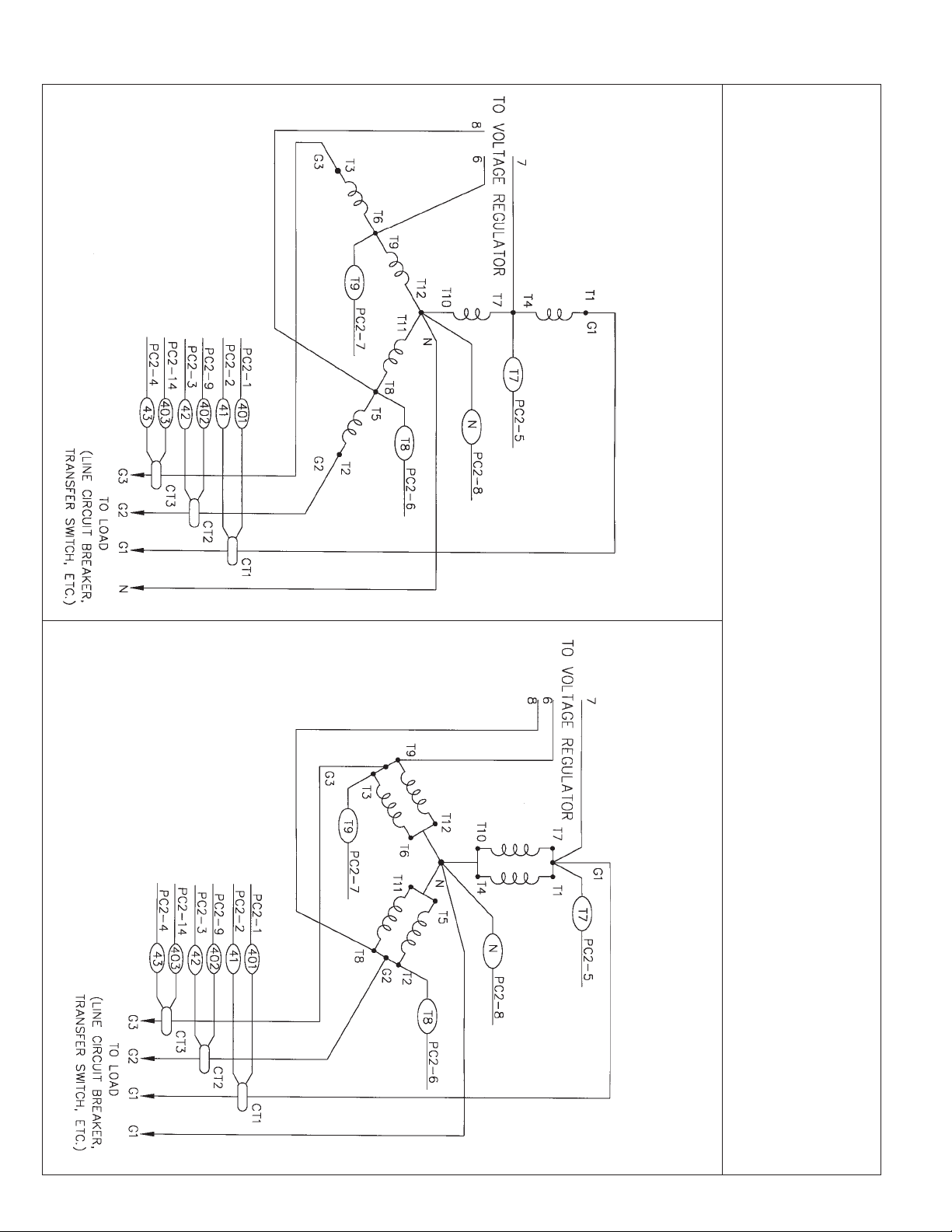
THREE PHASE-HIGH WYE
277/480 VOLTS
HIGH AND LOW WYE
THREE PHASE AC WIRING
U6 - T10
U2 - T4
U5 - T7
W6 - T12
W2 - T6
W5 - T9
U1 - T1
V6- T11
W1- T3
W =L3
N = N
V5 - T8
Lead Cross Ref.
U =L1
V =L2
V1 - T2
V2 - T5
THREE PHASE-LOW WYE
120/208 VOLTS
3113-00
Page 12
60706-156
Page 15
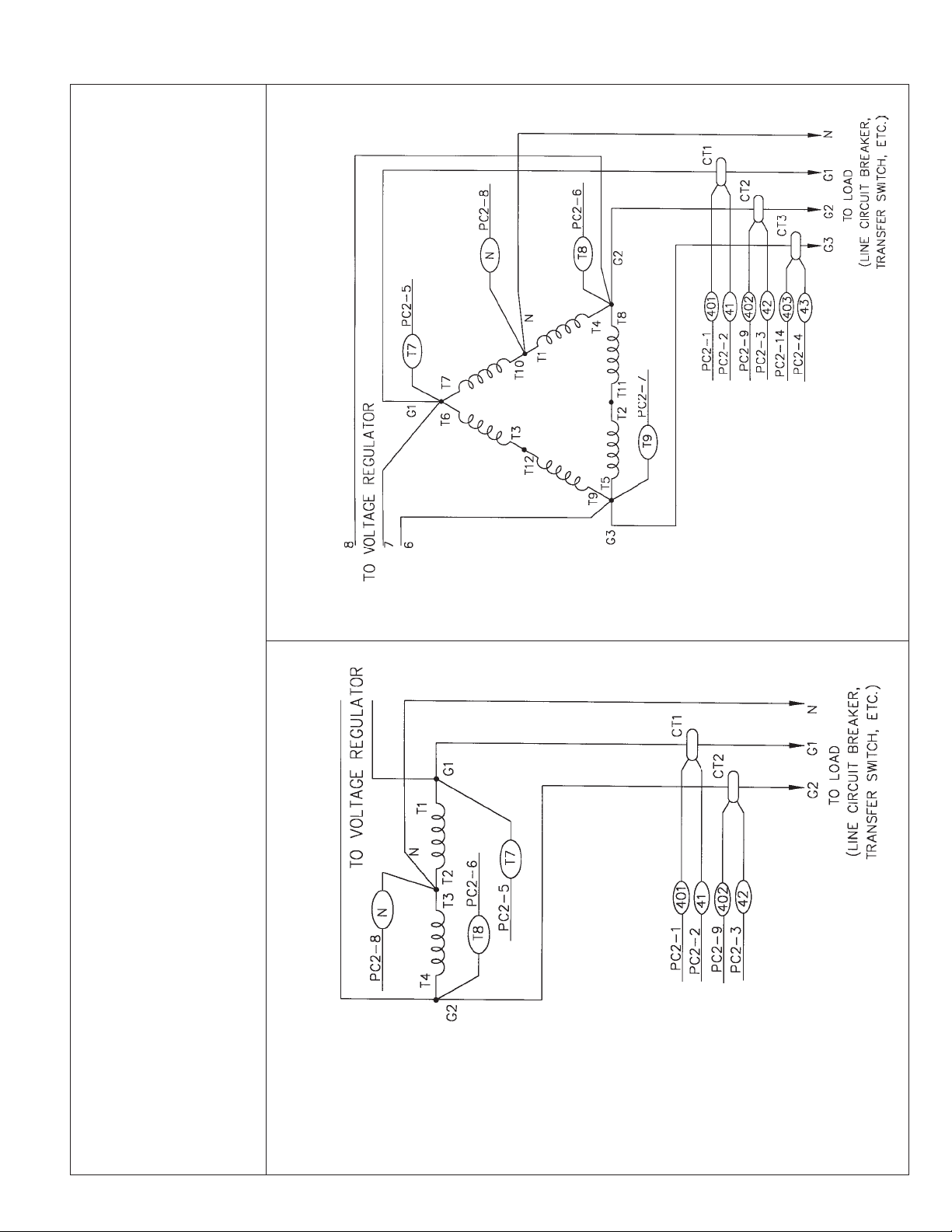
THREE PHASE -DELTA
120/240 VOLTS
V1 - T2
V2 - T5
V5 - T8
W1- T3
V6- T11
W2 - T6
W5 - T9
W6 - T12
SINGLE PHASE
120/240 VOLTS
V =L2
W =L3
N = N
U =L1
Lead Cross Ref.
U1 - T1
U2 - T4
U5 - T7
U6 - T10
60706-156
THREE PHASE AC WIRING - DELTA
SINGLE PHASE AC WIRING
Lead Cross Ref.
Page 13
N = N
U1 =L1
U6 =L3
U1 - T1
U2 - T2
U5 - T3
U6- T4
3113-00
Page 16

VOLTAGE REGULATOR WIRING
THREE PHASE AND SINGLE PHASE
3113-00
Page 14
60706-156
Page 17

DC SCHEMATIC
60706-156
Page 15
3113-00
Page 18

PSS50 & 75LS OUTLINE DRAWING AND WIRING ENTRANCE
3113-00
Page 16
60706-156
Page 19

12 MONTH LIMITED W ARRANTY
WINCO, Incorporated warrants to the original purchaser for 12 months that goods manufactured
or supplied by it will be free from defects in workmanship and material, provided such goods are
installed, operated and maintained in accordance with WINCO written instructions.
WINCO’s sole liability, and Purchaser’s sole remedy for a failure under this warranty, shall be
limited to the repair of the product. At WINCO’s option, material found to be defective in material
or workmanship under normal use and service will be repaired or replaced. For warranty service,
return the product within 12 months from the date of purchase, transportation charges prepaid, to
your nearest WINCO Authorized Service Center or to WINCO, Inc. at Le Center Minnesota.
THERE IS NO OTHER EXPRESS WARRANTY.
To the extent permitted by law, any and all warranties, including those of merchantability and
fitness for a particular purpose, are limited to 12 months from date of purchase. In no event is
WINCO liable for incidental or consequential damages.
Note: Some states do not allow limitation on the duration of implied warranty and some states do
not allow the exclusion or limitation of incidental or consequential damages, so the above limitations may not apply in every instance. This warranty gives you specific legal rights which may
vary from state to state.
WINCO reserves the right to change or improve its products without incurring any obligations to
make such changes or improvement on products purchased previously.
EXCLUSIONS:
WINCO does not warrant engines, batteries, or other component parts that are warranted by their
respective manufacturers.
WINCO does not warrant modifications or alterations which were not made by WINCO, Inc.
WINCO does not warrant products which have been subjected to misuse and/or negligence or
D=LAbeen involved in an accident.
60706-156
Page 17
3113-00
Page 20

60706-156-3113-00
225 SOUTH CORDOVA AVE
LE CENTER MN 56057
Phone - 507-357-6831
Fax - 507-357-4857
Website www:wincogen.com
 Loading...