

Page 1
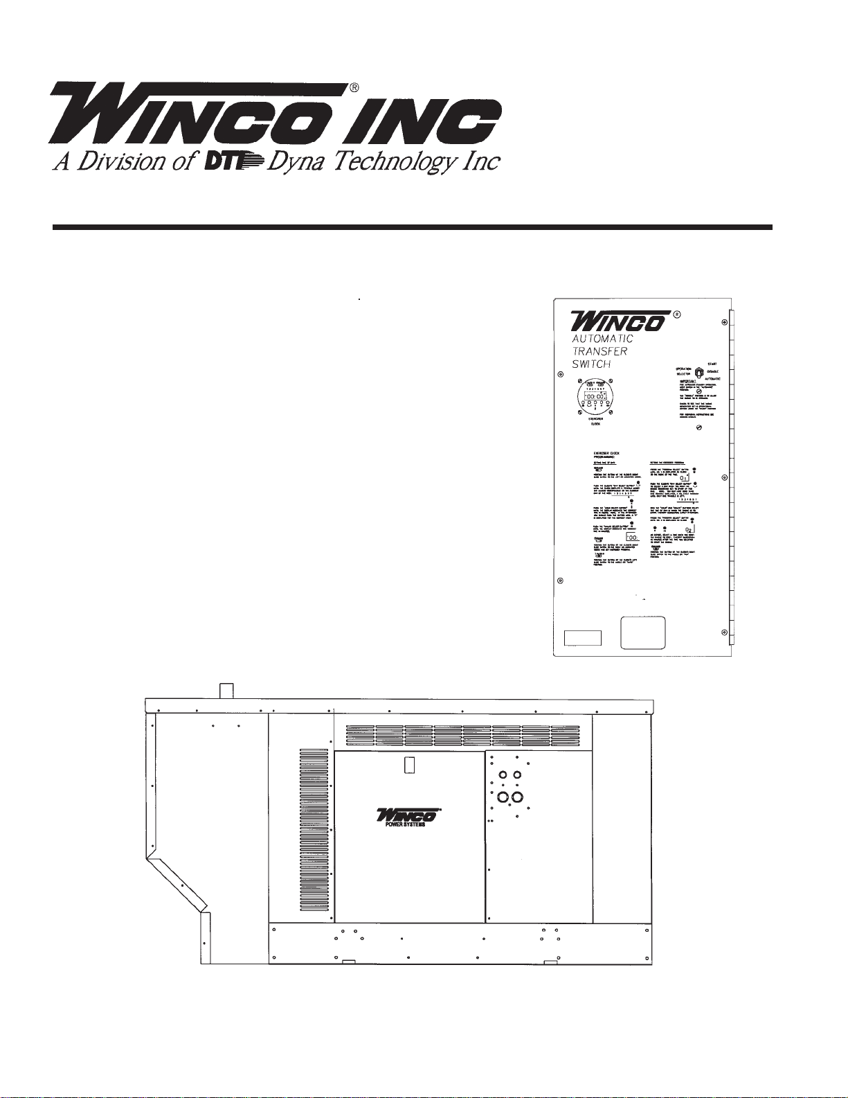
PACKAGED
STANDBY
SYSTEM
INST ALLA TION AND OPERA TORS MANUAL
PSS25000/A
Automatic Transfer
Switch
PSS25000/A
Engine Generator
P/N 60706-171-5076-10
Page 2

Read and understand all instructions in the
manual before starting and operating the
generator set.
USING THIS MANUAL
Congratulations on your choice of a Winco generator set.
You have selected a high-quality, precision-engineered
generator set designed and tested to give you years of
satisfactory service.
To get the best performance from your new engine
generator set, it is important that you carefully read and
follow the operating instructions in this manual.
Should you experience a problem please follow the
“Things To Check” near the end of this manual. The
warranty listed in this manual describes what you can
expect from WINCO should you need service assis-
tance in the future.
TABLE OF CONTENTS
INTRODUCTION i
GUIDE TO PRODUCT SAFETY 1
BASIC INFORMATION 2
Description 2
Specification Table 3
PREPARING THE UNIT 3
Unpacking the Unit 3
ENGINE GENERA TOR INST ALLATION 4
Installation 4
Fuel Installation 4
Vapor Fuel Pressure Tables 5
Liquid Withdrawal 6
Fuel Adjustments 6
Fuel Conversions 6
Lubrication 7
Battery Installation 7
Connecting Battery Charger &
Blockheater 7
TRANSFER SWITCH INST ALLATION 7
AC Electrical Connections 8
DC Electrical Connections 10
Exerciser Clock Set Up 11
INITIAL ST ART-UP 11
PROPER USE AND INSTALLATION
You must be sure your new engine generator set is:
* Properly serviced before starting
* Operated in a well ventilated area
* Properly exhausted and gases safely dispersed
* Wired by a qualified electrician
* Operated only for its designed purposes
* Used only by operators who understand its operation
* Properly maintained
COPY YOUR MODEL AND SERIAL
NUMBER HERE
No other WINCO generator has the same serial number
as yours. It is important that you record the number
and other vital information here. If you should ever
need to contact us on this unit it will help us to respond
to your needs faster.
MODEL____________________________________
SERIAL NUMBER____________________________
PURCHASE DATE____________________________
DEALER___________________________________
DEALER PHONE # ___________________________
TROUBLESHOOTING INFORMATION 12
WIRING DIAGRAMS
NON-UL ATS Wiring Diagram 14
Winco/Zenith UL ATS Schematics 15
ASCO 165 UL ATS Schematics 16
PSS25000 Layout 17
DC Schematic 18
AC Schematic 19
AC Schematic 20
MAINTENANCE LOG 21
12 MONTH WARRANTY 22
P AGE i
Page 3

SAFETY INFORMATION
This engine generator set has been designed and
manufactured to allow safe, reliable performance.
Poor maintenance, improper or careless use can
result in potential deadly hazards; from electrical
shock, exhaust gas asphyxiation, or fire. Please read
all safety instructions carefully before installation or
use. Keep these instructions handy for future
reference. Take special note and follow all warnings
on the unit labels and in the manuals.
ANSI SAFETY DEFINITIONS
************************************************************
DANGER:
DANGER indicates an imminently hazardous
situation which, if not avoided, will result in death or
serious injury. This signal word is to be limited to the
most extreme situations.
***********************************************************
************************************************************
WARNING:
WARNING indicates a potentially hazardous situation
which, if not avoided, could result in death or serious
injury.
***********************************************************
***********************************************************
CAUTION:
CAUTION indicates a potentially hazardous situation
which, if not avoided, may result in minor or moderate
injury. It may also be used to alert against unsafe
practices.
************************************************************
NOTE:
CAUTION is also used on the unit labels and in this
manual to indicate a situation that could result in
serious damage or destruction of the equipment and
possible personal injury.
1. ELECTRIC SHOCK - The output voltage present in this
equipment can cause a fatal electric shock. This
equipment must be operated by a responsible
person.
before refueling.
b. Keep fuel containers out of reach of children.
c. Do not smoke or use open flame near the
generator set or fuel tank.
d. Keep a fire extinguisher nearby and know its
proper use. Fire extinguishers rated ABC by
NFPA are appropriate.
e. Store fuel only in an approved container, and only
in a well-ventilated area.
f. Follow local codes for closeness to combustible
material.
3. DEADL Y EXHAUST GAS - Exhaust fumes from any
gasoline engine contain carbon monoxide, an
invisible, odorless and deadly gas that must be mixed
with fresh air.
a. Operate only in well ventilated areas.
b. Never operate indoors.
c. Never operate the unit in such a way as to allow
exhaust gases to seep back into closed rooms
(i.e. through windows, walls or floors).
4. NOISE HAZARD - Excessive noise is not only tiring,
but continual exposure can lead to loss of hearing.
a. Use hearing protection equipment when working
around this equipment for long periods of time.
b. Keep your neighbors in mind when permanently
installing this equipment.
5. CLEANLINESS - Keep the generator and surrounding
area clean.
a. Remove all grease, ice, snow or materials that
create slippery conditions around the unit.
b. Remove any rags or other material that could
create potential fire hazards.
c. Carefully clean up any gas or oil spills before
starting the unit.
d. Never allow leaves or other flammable material
to build up around the engine intake or exhaust
area.
6. SERVICING EQUIPMENT - All service, including the
installation or replacement of service parts, should be
performed only by a qualified technician.
a. Do not allow anyone to operate the generator
without proper instruction.
b. Guard against electric shock.
c. Avoid contact with live terminals or receptacles.
d. Use extreme care if operating this unit in rain or
snow.
e. Use only three-prong grounded receptacles and
extension cords.
f. Be sure the unit is properly grounded to an
external ground rod driven into the earth.
2. FIRE HAZARD - Natural gas and LP present a hazard
of possible explosion and/or fire.
a. Do not refuel when the engine is running or hot.
Allow the engine to cool at least two minutes
5076-10 60706-171
PAGE 1
a. Use only factory approved repair parts.
b. Do not work on this equipment when fatigued.
c. Never remove the protective guards, cover, or
receptacle panels while the engine is running.
d. Use extreme caution when working on electrical
components. High output voltages from this
equipment can cause serious injury or death.
e. Always avoid hot mufflers, exhaust manifolds,
an d engine parts. They all can cause severe
burns instantly.
f. Installing a generator set is not a “do-it-yourself”
project. Consult a qualified, licensed electrician
or contractor. The installation must comply
with all national, state, and local codes.
Page 4

TESTING POLICY:
Before any generator is shipped from the factory, it is
fully checked for performance. The generator is loaded
to its full capacity, and the voltage, current, and frequency
are carefully checked.
Rated output of generators is based on engineering
tests of typical units, and is subject to, and limited by, the
temperature, altitude, fuel, and other conditions specified
by the manufacturer of the applicable engines.
INTRODUCTION AND DESCRIPTION
The package standby system includes all items
necessary for a completely automatic standby power
system as standard equipment.
DESCRIPTION
This package standby system is designed to automatically provide standby power to unattended loads
during electrical outages. Upon an interruption of normal
electrical service the package standby systems electrical
control circuits will automatically start the engine. The
generator will produce electrical power and the Automatic
Transfer Switch (A.T.S.) will automatically transfer the
electrical loads to the engine-generator set. Upon
restoration of normal electrical service the emergency
transfer switch will sense return of the normal commercial power. The Automatic Transfer Switch will retransfer
the load back to the normal commercial power source.
The engine control circuits will begin a cool-down cycle,
after which the fuel supply will be shut off and the engine
ignition system disabled.
These packaged standby systems consist of two
major components:
1) AUTOMATIC TRANSFER SWITCH
A wall mounted Automatic Transfer Switch (A.T.S.)
designed for inside installation. The A.T.S. consists of a
line side contactor and a generator side contactor. The
contactors are both electrically and mechanically
interlocked. An electronic exerciser clock is installed in
the A.T.S. as standard equipment. The A.T.S. also
contains the power failure sensing circuitry necessary to
send a start/stop signal to the engine generator set.
Optional UL Automatic Transfer Switch Sizes
UNIT LINE SIDE GENERATOR
CONTACTOR SIDE CONTACTOR
PSS25000 100 AMPS 100 AMPS
200 AMPS 200 AMPS
Both the 100 amps and the 200 amps UL Switches are
available in single and three phase.
Additional optional A.T.S. sizes are available to meet
specific needs. Contact your local WINCO Rep. or the
WINCO Sales Department for a quote.
2) ENGINE/GENERATOR
PSS25000 - The engine generator set consists of a
Ford Industrial, four cylinder, water cooled engine
equipped to run on LP or NG fuel. The engine operates at
3600 rpm and frequency regulation is maintained at 60
Hz, by an electronic governor mounted on the engine.
The 25,000 watt (25kW) generator is a single bearing,
direct drive, rotating field design, with an automatic
voltage regulator installed to maintain normal voltage
under full load conditions. The generator is connected to
the engine flywheel via a flexible drive disk. The engine
generator is mounted in a water tight enclosure for
outside installation. Connection boxes are provided for
all customer connections (both AC output and DC
control). A customer supplied 500 CCA (BCI group 24)
battery is required to complete the installation. Engine
operation is controlled by an Electronic Engine Control
Module (E.C.M.) mounted in the engine generator
enclosure. The E.C.M. is equipped standard with a 3
second start delay, 3 minute cool down delay and cycle
cranking consisting of five, 12 second on/12 second off
cycles. The E.C.M. has both oil pressure and high water
temperature delays build into the starting circuit. During
initial start up the oil pressure delay is 12 seconds, to
allow the engine time to build oil pressure, before a
shutdown will occur. The high water temperature
shutdown has a 60 to 90 second lockout, allowing the
engine time to clear the hot water out of the block in case
of a hot restart. In addition if the generator should lose
output during a run cycle the engine will continue to run
for about 60 seconds and then shutdown and display an
overcrank light. The starter will not re-engage until the
generator selector switch has been cycled off and back
on. This is the only way to clear a fault light.
Standard Automatic Transfer Switch Sizes
(NON-UL)
UNIT LINE SIDE GENERATOR
CONT ACT OR SIDE CONTACTOR
PSS25000 230 AMPS 150 AMPS
** NOTICE **
This unit will automatically transfer if a power outage
occurs while running in an exercise mode.
PAGE 260706-171
5076-10
Page 5

SPECIFICATIONS
UNPACKING INSTRUCTIONS
GENERATOR
MODEL WATTS* VOLTS Pf AMPS* HZ pH RPM
PSS25000 25,000 120/240 1.0 104.0 60 1 3600
PSS25000-4 25,000 120/208 . 8 86.8 60 3 3600
PSS25000-17 25,000 120/240 .8 75.3 60 3 3600
PSS25000-18 25,000 277/480 .8 36.6 60 3 3600
*Derate 10% for Natural Gas operation. Derate 3.5%
per 1000 feet elevation above sea level.
FUEL CONSUMPTION
NG LP
1000 BTU/CU FT 2520 BTU/CU FT
MODEL CF/HR BTU/HR #/HR GAL/HR CF/HR BTU/HR
PSS25000* 375 375,000 17.1 4.1 148 375,000
*Based on full load operation
LP TANK SIZING
Required LP Tank size for LP Vapor withdrawal operating at various outside temperatures given in degrees
Fahrenheit (Celsius)
TANK TEMPERA TURE
MODEL 60 f(16 c) 32 f(0 c) 0 f(-18 c) -20 f(-29 c)
PSS25000* 250 Gal. 500 Gal. 500 Gal. 1000 Gal.
* Fuel tank sizes for PSS25000 on liquid withdrawal are
considerably smaller consult your local fuel supplier.
** NOTICE **
When unpacking the generator set, be sure to inspect it
carefully for freight loss or damage. If loss or damage is
noted at the time of delivery, require that the person
making the delivery make note of the loss or damage on
the freight bill, or affix his signature under the consignor’s
memo of the loss or damage. Contact the carrier for
claim procedures.
When loss or damage is noted after delivery, segregate
the damaged material, and contact the carrier for claim
procedures. Be sure to retain the packaging material for
carrier inspection.
“Concealed Damage” is understood to mean damage
to the contents of a package which is not evident at the
time of delivery by the carrier, but which is discovered
later. The carrier or carriers are responsible for merchandise lost or damaged in transit. The title to goods
rests with the consignee when generators are shipped
F.O.B. factory, and only the consignee can legally file a
claim.
**** CAUTION ****
The PSS25000 is shipped with oil, and a 50/50 mix of
coolant. Be sure to check all fluid levels before operating. See engine manufacturer’s instruction manual for
recommended oil requirements before initial starting.
ENGINE SPECIFICATIONS:
Refer to engine operating and maintenance instructions.
** NOTICE **
Regarding Engines - This manual covers the generator
portion of these units. See the separate engine instruction manual for engine-related problems, detailed engine
information and engine warranty.
** CAUTION **
Be sure to check the engine oil level frequently, as
specified in the engine manual.
The engine manufacturer has established an excellent
worldwide engine service organization; engine service is
available from a nearby authorized dealer or distributor;
check the yellow pages of the telephone directory under
“engines,” or ask the dealer from whom you purchased
the power plant.
The rated power of each engine-generator is limited by
the temperature, altitude and all other ambient conditions
specified by the engine manufacturer. Engine power will
decrease 3-1/2% for each 1000 ft. above sea level, and
will decrease an additional 1% for each 10 degrees
Fahrenheit above 60 degrees Fahrenheit.
UNPACKING:
1. Carefully remove the carton.
2. After inspecting the engine-generator and transfer
switch for external physical damage, check for the
following items packed inside the carton.
a. Owner’s manual, wiring diagram and parts list.
b. Engine manufacturer’s instruction manual.
3. Remove main frame hold down bolts, (4).
4. Unit can now be lifted from shipping pallet.
5076-10 60706-171
PAGE 3
Page 6

INSTALLATION
FUEL INSTALLATION
General Information
*************
***** WARNING ****
*************
Before proceeding with the installation, be sure the
operation selector switch is in the stop position.
These engine/generator sets are designed to be
mounted on a concrete pad outdoors only. The transfer
switch is mounted next to your electrical entrance or
distribution panel inside the building. Consult a qualified, licensed electrician or contractor to install and wire
the transfer switch. The installation must comply with all
national, state and local codes.
***** CAUTION ****
EQUIPMENT DAMAGE - The PSS25000 must be
mounted on a full length solid concrete pad to prevent air
from exiting under the unit. Allowing air to exit under the
unit may cause the unit to overheat from lack of proper
air flow.
Before beginning the installation process recheck the
rating of the generator set and its transfer switch rating.
Be certain they can handle the intended load and are
compatible with the entrance voltage, phase and current
ratings. Plans for installation should be prepared with
proper attention to mechanical and electrical engineering
detail to assure a satisfactory system installation. The
information in this manual is offered only as a guide to
finalizing your installation plans. For full service switching
the A.T.S. must have a fusible disconnect (circuit breaker)
installed before the switch to protect transfer switch.
ENGINE GENERATOR SET MOUNTING
The unit’s main frame should be bolted solid to a four to
six inch thick cement pad. The engine-generator is
mounted on a sub-frame which is isolated with special
shock mounts on the main frame. This allows the
engine-generator to vibrate without affecting the control
panel on the main frame.
Do not install any shock mounts between the base
frame and the concrete pad. Engine vibration will be
transmitted to the control panel causing erroneous start/
stop cycles and premature control failure.
The unit should be mounted to allow for ample working
room around it. Particular attention should be paid to the
direction of the hot air discharge and exhaust discharge.
Unit location should be such that these discharges are not
allowed to be drawn back in through an open window or
door. A general rule to follow is five (5) feet of clearance
on all sides. (Code NFPA 37requires five feet from any
combustible surface.)
NOTE: All PSS25000 units are tested on Natural Gas
and shipped configured for Natural Gas. See page 6 for
conversion to LP
The fuel supply should be as close as possible to the
engine. This will reduce the installation cost of fuel runs.
The information in this manual is offered to assist you in
providing the proper fuel for your engine. However, this
information is only provided to inform you of the engine’s
requirements and assist in making you aware of the
decisions you must make. In no case should the
instructions or information provided be interpreted to
conflict with any local, state or national codes. If in doubt,
always consult your local fire marshal or gas supplier.
*************
***** WARNING ****
*************
FIRE HAZARD - All fuel runs should be installed by a
licensed fuel supplier.
Connect the fuel supply to the inlet of the fuel solenoid
(see table for recommended line size). For all vapor fuel
systems the delivery pressure of the fuel to the fuel
solenoid on the unit must be four to six ounces psi (per
square inch) or 7 to 11 inches W.C. (Water column).
Units equipped with liquid withdrawal kits must be
connected to the liquid withdraw valve on the tank. Full
tank pressure must be delivered to the 3/8” fuel fitting on
the fuel lock strainer at the generator. These fuel
pressures are critical, failure to provide the proper fuel
pressure can cause many problems ranging from a unit
that will not start to causing damage to the fuel system.
INSTALLING THE FUEL LINE
** NOTICE **
The engine generator sets are properly adjusted before
they leave the factory. A tag is attached to the unit that
specifies the fuel, natural gas (NG) or propane vapor (LP)
that the unit was set up and tested on. A slight adjustment may be necessary on NG depending on local BTU
content. This adjustment will be discussed later.
Line Size
Unit location will determine the size of fuel line that is
required to supply the engine with a constant fuel
pressure and volume. Refer to the tables below for fuel
line size, fuel consumption and recommended tank size.
For distances of 50 feet and over, a two regulator fuel
system is recommended. This is accomplished by
installing a primary regulator at the tank which will reduce
the tank pressure down to 10 to 15 lbs. A secondary
regulator is installed to further reduce the fuel pressure
to the required four (4) to six (6) oz. operating pressure.
This secondary regulator must be at least 10 feet from the
engine generator set, any closer installation will require a
larger line be installed to provide a fuel reservoir. This is
PAGE 460706-171
5076-10
Page 7
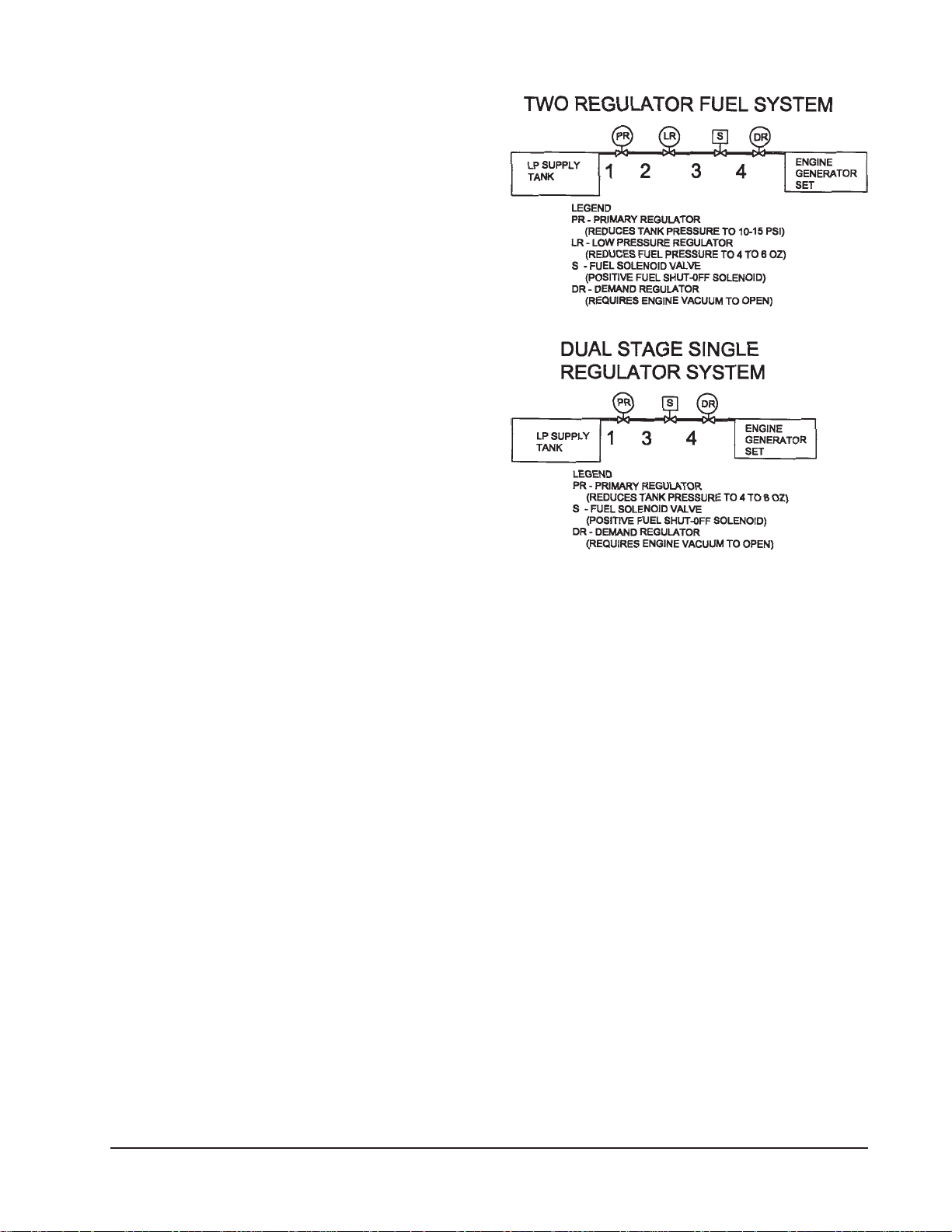
also true for the single dual stage regulators, they should
also be minimum of 10 feet from the unit. If this is not
done the demand regulator on the unit and the pressure
regulator in the fuel line will interfere with each other.
When this two (2) stage regulator system is used, a fuel
line size of 1/2 to 5/8 inch is generally adequate for
distances up to 300 feet from the primary to the secondary regulator. (Consult your local fuel supplier for your
exact requirements.) The appropriate line size from the
table below is then installed from the second regulator to
the generator set.
*************
***** WARNING ****
*************
PERSONAL DANGER - Do not use galvanized pipe in
fuel line runs. The galvanized coating can become
eroded and flake off, causing possible obstructions in the
regulator or fuel valve. The results could range from
inoperative engine start to hazardous fuel leaks.
NATURAL GAS or LP V APOR
Size of pipe normally required for generators operating
on NATURAL GAS or LP V APOR
up to 25 feet* 25 - 100 feet* over 100 feet*
use a two
PSS25000 1" pipe 1.25" pipe regulator system
*Allow an additional 3 feet for each standard elbow. Do not use
‘street ells’ (restrictive)*
LP LIQUID WITHDRAW AL (ONL Y)
Size of pipe normally required for generators operating
on LP LIQUID WITHDRAWAL
PSS25000 - 3/8” line for all distances.
**** CAUTION ****
Be careful when sealing gas joints. Excessive sealing
compound can be drawn into the solenoid, regulator or
carburetor causing an engine malfunction.
FUEL PRESSURE
Below is a table of the fuel pressure reading at each
reference in the system.
Fuel Pressure Table
Single Regulator (LP Vapor only)
1 3 4
UNIT OFF TANK PSI 7-11 in 7-11 in
4-6 oz. 4-6 oz.
STARTING TANK PSI 7-11 in 7-11 in
4-6 oz. 4-6 oz.
NO LOAD TANK PSI 7-11 in 7-11 in
4-6 oz. 4-6 oz.
FULL LOAD TANK PSI 7-11 in 7-11 in
4-6 oz. 4-6 oz.
LP & NG VAPOR FUEL
Correct fuel pressure cannot be stressed enough. The
most common cause for inoperative systems is an
inadequate or incorrect fuel pressure. Performance of
the engine is in direct relation to the correctness of the
fuel system. Shown below is a block diagram of a
typical LP or NG vapor fuel installation.
Notice the following tables give two (2) different units of
measuring fuel pressure. The first and most accurate is
the use of a simple water manometer. A manometer is
Two (2) Regulator System (LP Vapor only)
1 2 3 4
UNIT OFF TANK PSI 10-15 lbs 7-11 in 7-11 in
4-6 oz. 4-6 oz.
STARTING TANK PSI 10-15 lbs 7-11 in 7-11 in
4-6 oz. 4-6 oz.
NO LOAD TANK PSI 10-15 lbs 7-11 in 7-11 in
4-6 oz. 4-6 oz.
FULL LOAD TANK PSI 10-15 lbs 7-11 in 7-11 in
4-6 oz. 4-6 oz.
calibrated in inches of water column. The second is with
a pressure gauge calibrated in ounces per square inch.
Reference number 4 is the engine generator set.
5076-10 60706-171
PAGE 5
Page 8

Natural Gas
1 3 4
UNIT OFF LINE PSI 7-11 in 7-11 in
4-6 oz. 4-6 oz.
STARTING LINE PSI 7-11 in 7-11 in
4-6 oz. 4-6 oz.
NO LOAD LINE PSI 7-11 in 7-11 in
4-6 oz. 4-6 oz.
FULL LOAD LINE PSI 7-11 in 7-11 in
4-6 oz. 4-6 oz.
LP LIQUID WITHDRAW AL
The following is a block diagram of a typical L/P Liquid
Withdrawal fuel system for the PSS25000.
Tank Fuel Solenoid Converter Engine
1 2 3 4
Reference number 1 is the fuel tank. No regulator is
required but the tank must have a liquid withdrawal drop
tube installed in it and a liquid valve on the tank.
Reference numbers 2 through 4 are installed on the
engine generator set.
Liquid fuel is delivered from the tank directly to the fuel
solenoid on the generator at full tank pressure. This
system requires no pressure regulator be installed any
where in the system. The converter mounted on the
engine generator set will take the liquid fuel at tank
pressure and convert it to vapor at the proper delivery
rate.
LP/NG FUEL ADJUSTMENTS
**** CAUTION ****
Do not make any fuel adjustments or governor adjustments until all pressure readings are in compliance with
specification. See fuel pressure charts (tables 1, 2, and
3).
NATURAL GAS (NG)
Due to variations in NG fuel characteristics and BTU
levels throughout the country, it may be necessary to
readjust the fuel mixture once the engine has been
installed and serviced.
**** CAUTION ****
Never make a fuel mixture adjustment on a unit when it is
stopped or running no load. A mixture adjustment is only
effective when the engine is operating under load.
ADJUSTMENT PROCEDURE
1. Insure the unit is operating with an 80 to 100% load
or at the highest anticipated load.
Note: The mixture adjustment is located on the carbure-
tor just behind the fuel inlet hose. This mixture
adjustment is a partial turn, lean to rich, load block.
2. Begin making a mixture adjustment. Adjustments
should be made very slowly. Adjust back and forth until
the engine is running as smooth as possible.
3. The PSS25000 is equipped with an electronic
governor which requires no speed adjustment.
FUEL TYPE CONVERSION
If it should be necessary to change the type of fuel used
after a unit is received, the following procedures are
provided.
NA TURAL GAS TO PROPANE
1. Turn off fuel supply.
2. Remove the fuel line from the carburetor at the
demand regulator.
3. Remove the cap on the upright column of the
regulator. This will expose the pressure spring adjusting
screw. Back off the spring adjusting screw so there is just
enough room to replace the cover. Replace the cover.
4. Invert the regulator so it is positioned with the column
pointing down.
5. Reconnect the fuel line at the regulator.
6. Remove the 1/8 NPT plug (the one closest to fuel
solenoid) located on what is now the top of the regulator.
Connect a fuel pressure meter or a manometer where
the plug has been removed. Move the generator control
switch to the run position. As the unit starts to crank the
fuel solenoid will open and you should get a pressure
reading of between 4 to 6 ounces (7 to 11 inches of water
column).
7. If the pressure is correct, remove the meter and
reinstall the pipe plug.
8. You are now ready to make the final fuel mixture
adjustment. Refer to adjustment section in this manual.
PROP ANE TO NA TURAL GAS
1. Turn off fuel supply.
2. Remove the fuel line from the carburetor at the
demand regulator.
3. Invert the regulator so the column is in the upright
position. Remove the cap on the upright column of the
regulator. This will expose the pressure spring adjusting
screw. Turn the screw all the way out (CCW) and then
back in (CW) about 8 turns. The plug should be approximately half way down for initial starting.
4. Reconnect the fuel line at the regulator.
5. Remove the 1/8 NPT plug (the one closest to fuel
solenoid) located on what is now the bottom of the
regulator. Connect a fuel pressure meter or a manometer
where the plug has been removed. Move the generator
control switch to the run position. As the unit starts to
crank the fuel solenoid will open and you should get a
pressure reading of between 4 to 6 ounces (7 to 11
inches of water column).
PAGE 660706-171
5076-10
Page 9

6. If the pressure is correct, remove the meter and
reinstall the pipe plug. Next remove the 1/8 inch NPT plug
on the carburetor side of the regulator and install the
pressure meter. Move the generator switch to the run
position. As soon as the solenoid opens the pressure
should rise 2.5 to 3 oz. just as the engine starts to crank.
If it is within this range replace the cap on the column. If
not, adjust the screw down to increase and up to
decrease and retest.
7. You are now ready to make the final fuel mixture
adjustment. Refer to adjustment section in this manual.
LUBRICATION
Before starting the engine, check the oil and, refill if
required, the crankcase with the proper weight/grade of
oil, as recommended by the engine manufacturer’s
maintenance instructions. The necessity of using the
correct oil, and keeping the crankcase full cannot be over
emphasized.
INSTALLING THE BATTERY
**** CAUTION ****
In the following battery installation procedure, check to
be sure the selector switch remains in the “stop” position.
This should be your last step before initial start-up.
A customer supplied twelve-volt battery is required to
complete the installation. Installation of the highest CCA
rated battery, within the correct BCI group, will increase
cold weather starting performance. Use only Mainte-
nance Free batteries, this will reduce the need to refill the
battery with water. Gel batteries should not be used with
the battery tender installed in the generator enclosure.
MINIMUM
Model BCI Group CCA Rating
PSS25000 2 4 650
*****CAUTION*****
*****CAUTION*****
EQUIPMENT DAMAGE - NEVER jump start these units.
Doing so will destroy the engine control module rendering
the unit non-operational. Remove and fully recharge the
battery before attempting to start.
CONNECTING THE BATTERY CHARGER &
BLOCKHEATER
The battery tender and frost plug heater require a
GFCI circuit breaker protected AC circuit from your
distribution panel be run out to the engine generator set.
These AC wires can be run in the same conduit as the
other AC leads from the generator. It is suggested that
this GFCI circuit be fused for 15 amps, as both the battery
charger and the block heater are connected to this circuit.
These units have a duplex receptacle mounted on the
control panel just below the operational switches. The
wires for this receptacle have been routed up into the
generator connection box for your convenience. You will
make your connection from your 120 volt power feed in
the connection box.
A two-stage battery tender is provided on all these
generators. This battery tender charges at a rate of 750
mA until the battery is fully charged and then automatically switches to a 13.2 VDC float charger. The charger
has an indicator light on it, red indicates it is charging,
and green indicates it is in the storage mode (float
charge). The battery tender was shipped already plugged
into the duplex receptacle. All DC connections from the
battery tender to the battery have already been made.
A frost plug heater and thermostat are installed as
standard equipment. The thermostat used on these units
has a operating range of on at 22 degrees and off at 32
degrees air temperature. The heater is plugged into the
other receptacle on the duplex which has a thermostat in
series with the power feed. Do not reverse the recep-
tacles that the devices are plugged into or you will
end up with the battery charge on the thermostat
controlled circuit.
EQUIPMENT DAMAGE - Always connect the positive
cable first and the negative cable last, when disconnecting it is negative cable first and positive last. Failure to
connect and disconnect in the proper sequence can
cause equipment damage.
Observe polarities: connect the positive (+) battery
terminal to the (+) cable from the control panel; the
negative (-) battery terminal is connected to the negative
cable (ground) from the engine generator assembly.
All connections must be clean and tight. Check the
electrolyte (fluid) in the battery monthly to be sure it is
above the plates. Never allow the battery to remain in a
discharged condition.
5076-10 60706-171
PAGE 7
** NOTICE **
The battery tender is not intended to recharge a battery
which has become completely discharged. It is designed to produce enough current to recharge a slightly
low battery, maintaining it fully charged.
MOUNTING THE Non-UL
AUTOMA TIC TRANSFER SWITCH (A.T.S.)
*************
***** WARNING *****
*************
EQUIPMENT DAMAGE- Protect the switch from construction grit and metal chips to prevent a malfunction or
shortened life of the switch. Contactors returned for
warranty consideration with foreign material inside of them
will not be warranted.
Page 10

The Automatic Transfer Switch connects the load (lights,
furnace, outlets, etc.) to the normal power line during
standby. When normal power fails, the A.T.S. starts the
engine generator set, disconnects the power line and then
connects the load to the standby generator set. When
normal power is restored, the automatic switch retransfers
the electrical load to the normal service and stops the
engine. The A.T.S. panel should be mounted as close to
the distribution panel as possible.
*****NOTE*****
EQUIPMENT DAMAGE- The standard NON-UL Winco
Single Phase ATS does not protect against undervoltage.
If you are in an area that is suspectable to brown outs
(low voltage) you may want to consider adding an
undervoltage sensor to standard ATS panel.
*************
***** WARNING *****
*************
All wiring must be done by a licensed electrician, and
must conform to the national electrical code and comply
with all state and local codes and regulations. Check with
your electrical inspectors before proceeding!
The standard Non-UL Automatic Transfer Switch used
with the PSS25000 system has a 230 Amp line side
contactor installed to handle your normal power needs
and a 150 Amp generator side contactor to handle the
emergency generator output. Before installing the A.T.S.
you must first ensure that the 230 Amp line side contactor will be sufficient to handle your complete service. See
Figure 3. (i.e. the main line breaker must not be larger
than 230 Amps). If you have a larger main line breaker,
you will not be able to transfer the complete electrical
system. In this case it will be necessary to install a
secondary emergency distribution panel. See Figure 4.
NOTE: THE MAXIMUM OUTPUT OF THE GENERAT OR IS
104 AMPS A T 240 VOL TS SINGLE PHASE, 86 AMPS A T
208 VOLTS, 75 AMPS A T 240 VOL TS AND 37 AMPS A T
480 VOLTS THREE PHASE. You must also take this into
consideration when deciding whether to install an
emergency distribution panel.
*************
***** DANGER *****
*************
Be certain the operation selector switch on the front of the
A.T.S. Control is in the “stop” position and the main power
switch “off”. For your own protection, verify these important safety precautions yourself with reliable instruments
before proceeding.
Single Phase
Generator Connections
To gain access to the customer connections, remove
the panel the warning light and the selector switch are
mounted on, inside the left hand access door. Both AC
and DC connections are made behind this panel. For
your convenience you may also access these connections
by removing the housing end panel on the generator end
of the housing and removing the back panel of the
engine control box. Four AC power leads are required
between the generator and the A.T.S. The power leads
coming into this connection box from the generator end
are labeled G1, G3, N for neutral and a ground wire to the
grounding lug. The engine control leads are currently
connected to some of the generator leads. These leads
must remain with the generator leads they are connected
to. The neutral lead is shipped not bonded to the ground,
current code requires the generator to be wired with an
isolated neutral. This will require you to run four AC leads
from the generator to the A.T.S. as you will need to run
both a neutral and a ground lead. All wires must be sized
to handle 104 amps minimum, the type of wire you use
will determine the gauge required. Consult your local wire
supplier for proper gauge and type for your installation.
A.T.S. Connections (Winco NON-UL Only)
The standby generator terminals in the A.T.S are
marked “GENERATOR - G1, G-N, G3”. The “hot” leads
G1 and G3 from the generator are wired to the generator
FIGURE 3
Full System
Single Phase
A.C. ELECTRICAL CONNECTIONS
*************
***** WARNING *****
*************
A FUSED DISCONNECT OR CIRCUIT BREAKER
MUST BE INSTALLED BETWEEN THE GENERATOR
AND THE A.T.S. PANEL TO PREVENT OVERLOADING
AND BURNING OUT THE GENERATOR. FAILURE TO
PROVIDE A FUSED DISCONNECT OR CIRCUIT
BREAKER, RATED AT GENERATOR RATING WILL
VOID YOUR WARRANTY IN CASE OF GENERATOR
FAILURE.
PAGE 860706-171
5076-10
Page 11

FIGURE 4
P ARTIAL SYSTEM
SINGLE PHASE
FIGURE 5
FULL SYSTEM
THREE PHASE
The load terminals in the A.T.S. are marked “LOAD - T1,
T-N, T3”. The “hot” leads T1 and T3 will wire directly to
the lugs between the two contactors marked “LOAD”.
Copper jumper straps have already been installed
between the upper terminals on the generator contactor
and the lower terminals on the line side contactors. The
T-N connection will be made on the stand-off in the
bottom of the ATS.
The Ground leads can be connected to the ground lug
in the ATS, or they can be bonded together along with a
lead from the ground lug. The ATS must be grounded to
the system ground.
PSS25000 Three Phase (FIGURE 5)
The three phase units are installed the same as the
single phase units above, except a fifth power lead is
added, (i.e. a G2 from the generator, L2 on the line side
and a T2 on the load side). In the 120/240 volt configuration the G3, L3 and T3 will be the high voltage (wild) leg.
The other difference is a three phase power monitor
has been installed in the A.T.S. to monitor each phase for
low voltage. This three phase monitor is phase rotation
sensitive and comes from the factory set up for A-B-C
phase rotation. If you have trouble getting the A.T.S. to
pickup the line power on initial installation, try switching
the A and B phase on the monitor. Your rotation may be
C-B-A. If so, be sure to match the generator rotation to
your current line rotation or your three phase motors will
try to turn backwards.
*************
***** WARNING *****
*************
When installing a Three Phase 240 Volt Delta system be
sure you know which lead is the high voltage leg (208
Volt line to neutral). The generator has the high voltage
lead connected at G3.
INSTALLATION NOTES
The load current carrying wires (L) and (T) must be
sized to handle the maximum load current without
excessive voltage drop. By code, the wire must be heavy
enough to handle the full current rating of the main line
circuit-breaker (or fuse) in the entrance (or sub-panel)
protecting the contactor switch.
All wires should be installed in rigid or flexible conduit.
(Knockouts are provided in the control box).
Because of the many different types of service, feeder,
and distribution equipment, no specific wiring instruc-
side contactor, terminals G1 and G3. The G-N connection
will be made on the stand-off in the bottom of the ATS.
The line terminals in the A.T.S. are marked “LINE - L1,
L-N, L3”. The “hot” load leads L1 and L3 are wired line
side contactor, terminals L1 and L3. The L-N connection
will be made on the stand-off in the bottom of the ATS.
5076-10 60706-171
PAGE 9
tions can be provided. It is, however, recommended that
only copper wire be used. In all cases it is essential that
while the load is connected to the generator, there can be
absolutely no feedback from the generator to the power
line or the power line to the generator. When properly
installed, the normal A.T.S. Control and safety systems
will eliminate all paths for feedback. Check with your local
electrical inspector on applicable local, state and federal
codes.
Page 12

NOTE:
Code requires a fuse disconnect (circuit breaker) be
installed in the incoming power line wiring directly in front
of the A.T.S. panel. This will allow you to test the generator under load. Should you ever have to work on the
switch, you will be able to disconnect the power and work
on the switch cold without having the power company pull
your meter.
To wire the automatic transfer switch into the existing
wiring, first determine which circuits will be on the
emergency load circuit. If the entire load is to be transferred, the transfer switch can be wired in directly after the
watt-hour meter or main entrance providing the service
entrance ampere rating is within the transfer switch’s
rated capability.
If only specific circuits are to be powered under
emergency power failure conditions, an additional
distribution panel designated “emergency distribution
panel” must be installed.
All selected emergency circuits are removed from main
distribution panels and reinstalled in the emergency
distribution panel. Suggested circuits: freezer, refrigerator, furnace, emergency lights, sump pump, emergency
outlet circuits, etc. Total running load must not exceed
generator rating.
The control wires will be connected as follows in the
generator control terminal box:
ATS Panel Generator Control Panel
Start 1 to Wire #S1
Start 23 to Wire #S23
The control wires will be connected in the generator
control terminal box and in the A.T.S. to small terminal
blocks. Both are labeled “Start 1” and “Start 23”. The
wires are run between identical terminals, i.e. “Start 1” to
“Start 1” etc.
UL ATS
Winco\Zenith
The only significant difference when make your DC
connections in the UL ATS is the terminal markings in the
UL ATS. Instead of being marked “Start 1” and Start 23”
they are marked start contacts “X1” and “X2”. The wire
labeled “Start 1” is routed to start contact X1” and the wire
labeled “Start 23” is routed to start contact “X2”
AUTOMATIC TRANSFERS SWITCH
CONNECTIONS UL-ATS
See the manual shipped with the Automatic Transfer
Switch for connection locations in the switch. Connections in each switch will vary depending on the type of
switch and the manufacturer.
*************
***** WARNING *****
*************
All UL transfer switches are phase rotation sensitive
and voltage sensitive. If you can not get the line power
or the generator to operate the ATS properly check
both your phase rotation on three phase switches and
proper voltage levels on all switches.
D.C. ELECTRICAL INTERCONNECTION
*******CAUTION******
Never run the AC and DC wiring in the same conduit.
WINCO NON-UL ATS
Two control wires are required to be installed between
the A.T.S. panel and the generator control terminal box.
Depending on the distance 14 to 16 gauge stranded wire
should be used. These wires will be labeled “Start 1”,
and “Start 23”.
X1
X2
ASCO 165 UL SWITCH
Your DC connection points in the ASCO 165 ATS are
terminals “4” and “5 on the interface terminal block.
PAGE 1060706-171
5076-10
Page 13

ASCO 300 UL SWITCH
Your DC connection points in the ASCO 300 ATS are
terminals “14” and “15”. Depending on the size of the
switch they are located in different locations. See below:
want the engine generator set to start up and run. Note:
You can get more than one triangle displayed on the
clock. If this happens just keep pressing the button and it
will work back through the cycle and display only one
triangle under whichever day you desire.
5. With the “Hour” and “Minute” buttons select the time of
day you want the engine to start up.
6. Press the “Program Select Button” until No. 2 is
displayed on the clock.
7. Push the “Day Select Button” to select the day you
want the engine to stop. This must be the same day you
selected in step 4 above.
8. With the “Hour” and “Minute” buttons, select the time
you want the engine to stop. It is recommended you let
the engine run at least 15 minutes during any exercise
period.
9. Position the top right hand (RUN) slide switch to the
center (RUN) position.
CLOCK NOTES:
This seven day exerciser clock has seven additional
program cycles available. Always keep in mind the odd
number turns the unit on and the even number shuts the
unit off. (i.e. (3 on, 4 off) (5 on, 6 off) etc.)
SETTING THE EXERCISER CLOCK
For Winco Non-UL only for all UL ATS see the instruction
manual shipped with the ATS.
Setting the current time and date.
1. Position the top right hand (RUN) slide switch to the
left position.
2. Push the clock’s “Day Select Button” until the clock
displays a triangle under the number corresponding to
the current day of the week. (Monday is day 1, Sunday is
day 7)
3. Push the “Hour Select Button” until the display
indicates the correct time in hours. Note: In the afternoon
you should push the button until a “P” is displayed
beside the correct hour.
4. Push the “Minute Select Button” until the display
indicates the correct time in minutes.
5. Position the top right hand (RUN) slide switch to the
center position. The correct time and date should now
be displayed.
Setting the Exerciser Program:
1. Position the top right hand (RUN) slide switch to the
right hand position.
2. Position the top left hand (AUTO) slide switch to the
center position.
3. Press the “Program Select Button” until No. 1 is
displayed on the clock to the right of the time.
4. Push the “Day Select Button” to select the day you
The relay in the clock will not work unless the transfer
switch is installed and powered up. The relay needs 120
volts AC to operate.
If, when you finish programming the clock, you get an
“EEEE” on the display, it stands for error. The most
common error is that the day of operation has not been
properly set at each step or a program has been turned
on and not turned off. (i.e. programs not properly grouped
1& 2, 3 & 4, 5 & 6, etc.)
On the face of clock is a small button marked “R”, this
is a reset switch. Depressing this switch will remove all
programming in the clock including the time. Use a small
screwdriver or the tip of a pencil to depress this button.
This should be used only as a last resort.
INITIAL START UP
*************
***** WARNING *****
*************
DO NOT jump start these engine generator sets. Starting
these units on a low battery or jump starting them will
cause damage to the engine control module.
Use the following check list to verify correct installa-
tion before starting the engine:
F Engine oil.* Check level & fill as required with
proper grade/qty.
F Engine coolant.* Check level & fill as required
with proper mixture.
F Unit mounting base properly bolted down.
F Clearance for service and maintenance on all
sides.
5076-10 60706-171
PAGE 11
Page 14

F Proper fuel line material, and size.
F All fuel line connections tight.
F Fuel line protected and a moisture trap installed
(may be required for NG).
F LP/NG pressure O.K. 4-6 Oz. (7-11" WC).
F Battery connections clean and tight.
F Battery fully charged.
F All A.C. and D.C. wiring installed and properly
protected.
* Refer to engine owners manual for proper
levels and type.
After completing the above checklist, the engine-
generator set is ready for the initial start-up test.
PROCEDURE
Move the selector switch on the engine generator to the
“RUN” position. The engine-generator will crank and
start automatically. If the engine fails to start, return
selector switch to the “stop” position and correct the
trouble before proceeding.
With the engine running smooth, check the no load
voltage and frequency at terminals G1 and G3 on the
generator terminal block in the A.T.S. The voltage
between G1 and G3 should be between 235-245 volts.
The frequency should be between 60.0 to 60.5 hertz. The
voltage should also be checked between the hot termi-
nals (G1 and G3) and the G-N to be certain of a balanced
voltage output and a solid neutral connection. The
voltage between G1 and G-N should be about one half of
the line to line (G1 to G3) voltage.
** Notice **
If for any reason during the check out procedure the
voltage and frequency are not correct, turn the selector
switch to the “STOP” position and correct the trouble
before proceeding.
After verifying the voltage and frequency are correct, turn
the selector switch to the “STOP” position. The unit
should shut off with no time delay. You are now ready to
test the automatic start function.
Move the selector switch on the engine generator set to
the “AUTOMATIC” position. For Non-UL Winco Automatic
Transfer Switches follow the instruction below. For All UL
Transfer Switches follow the instruction in the operators
manual you received with your transfer switch. For the
UL A.T.S. if you get a fault light during the initial start up or
prior to start up it is most likely a false warning light.
Simply reset the A.T.S. and start over.
Next you need to test the complete system. To accomplish this you will have to fail the incoming line power to
the A.T.S. panel. First move both selector switches to the
automatic position. Then fail the incoming power. All the
loads connected to the A.T.S. should now be dead. The
engine generator set will go into a 10 second start delay.
At the end of the start delay the unit will start up. As soon
as the engine generator set reaches operating speed the
generator side contactor will close and the load will be
applied to the engine generator.
Restoring the line power will cause the generator side
contactor in the A.T.S. to open. The line side contactor
will close as soon as the generator side contactor clears
the mechanical interlock and closes the electrical interlock. These interlocks ensure that you get a clean ‘break
before make’ action in the transfer switch.
The restoration of line power also sends a stop signal
to the engine generator set. This stop signal will activate
a cool down timer circuit. The engine generator will shut
down 3 minutes later.
This completes your installation and unit testing.
ALWAYS leave the system in automatic mode unless
servicing the unit. For automatic operation, keep both the
generator set and transfer selector switches in the
“AUTOMA TIC” position.
TROUBLESHOOTING TABLES
UNIT WILL NOT CRANK WHEN THE
POWER FAILS.
1. Alarm light on from previous run cycle.
2. Generator control switch not in “AUTOMATIC”
position.
3. Transfer control switch not in “AUTOMATIC”
position.
4. Low or dead battery.
5. Incorrect wiring between transfer switch and
generator.
6. Defective start stop relay in the transfer switch.
7. Circuit breaker tripped on engine control panel.
8. 3/4 amp fuse blown inside engine control.
9. Defective engine control module.
10. Loose or dirty battery terminals.
11. Defective “Run/Auto” switch on generator or
transfer switch.
12. Defective starter.
13. Defective start solenoid.
14. Defective remote start solenoid
Next move the selector switch on the A.T.S. panel to the
“START” position. The unit will go into a 10 second start
delay and then start up. If it fails to start at this time, check
your DC inter connection wiring. When the selector
switch on the A.T.S. is moved to the “DISABLE” position
the unit will go into a cool down period and then shut off.
The cool down period is 3 minutes. As long as line
power is still applied to the transfer switch during this test
period the A.T.S. will not transfer the load to the generator.
ENGINE WILL NOT CRANK WITH GENERATOR
SELECTOR SWITCH IN THE RUN POSITION.
1. Battery dead.
2. DC circuit breaker on control module tripped.
3. 3/4 amp fuse blown inside control module.
4. Defective engine controller.
5. Loose or dirty battery terminals
6. Defective “Run/Auto” switch on generator.
7. Defective starter.
PAGE 1260706-171
5076-10
Page 15

8. Defective start solenoid.
9. Defective remote start solenoid.
10. Locked up engine generator set.
ENGINE CRANKS BUT WILL NOT START.
1. Improper fuel pressure being delivered to unit.
2. Fuel supply shut off.
3. Fuel tank empty.
4. Defective spark plug.
5. Defective engine ignition module.
6. Dirty air cleaner filter.
7. Defective fuel solenoid valve.
8. Low voltage from battery to fuel solenoid, must
hold 12 volts during cranking.
ENGINE ST ARTS AND THEN STOPS AND
A F AULT LIGHT COMES ON.
1. Engine is low on oil.
2. Engine has high water temperature.
3. Engine has gone into overspeed.
4. Engine has gone into overcrank.
5. No output signal from engine ignition module to
engine control module.
NO AC OUTPUT FROM GENERATOR.
1. Defective rectifier.
2. Defective capacitor.
3. Defective armature.
4. Defective field coils.
5. AC short in the output leads.
6. Unit has lost its residual voltage.
7. Low engine speed, must be 3600 RPM.
8. Defective Voltage Regulator
PREVENTIVE MAINTENANCE
Reasonable care in preventive maintenance will insure
high reliability and a long life for the engine generator set
and the Automatic Transfer Switch.
*************
***** WARNING ****
*************
When performing any type of maintenance on this
equipment make sure the selector switch on the engine
generator is in the off position. If you are working in the
Automatic Transfer Switch, confirm with a reliable meter
that all power has been disconnected.
ENGINE WILL NOT COME UP TO SPEED
AFTER IT ST ARTS.
1. Insufficient fuel volume getting to the unit.
a. Fuel line too small.
b. Fuel pressure to low.
2. Fuel load block needs to be adjusted.
3. Governor is out of adjustment.
4. AC short in generator components.
5. Wiring to the A.T.S. panel crossed or shorted.
6. Unit is overloaded, check load amperage.
ATS P ANEL WILL NOT TRANSFER TO
EMERGENCY SUPPLY (GENERATOR).
1. No AC generator output from generator.
2. Broken or defective mechanical/electrical inter
locks.
3. Defective holding coil in the generator side
contactor.
4. Wiring error between generator and transfer
switch.
5. Defective start/stop relay in ATS.
ATS PANEL WILL NOT PULL IN ON
NORMAL POWER.
1. Proper normal line power not available at line
terminals in ATS panel.
2. Defective holding coil in line side contactor.
3. Broken or defective mechanical/electrical
interlocks.
4. Defective start/stop relay in ATS.
5. Three phase AC is wrong rotation for three phase
power monitor. (Three phase units only)
AUTOMATIC TRANSFER SWITCH
Clean and inspect the switch once a year. De-energize
all power sources, both line and engine generator set,
then brush and vacuum away any excessive dust and
dirty accumulation. You can at this time with the contactor
de-energized remove the contactor covers and check the
contacts. Make sure the contacts are clean and not
burned or pitted.
ENGINE GENERATOR SET
Service the engine in accordance with the engine
manufacture manual provided with your new equipment.
Routinely remove debris and dirt from around and inside
generator enclosure. Insure that the air intakes are free
from leaves and other debris at all times.
Clean and inspect battery terminals at least twice a
year. Check the battery water level at least twice a year
also.
Other than keeping the generator clean and free of
debris there is no other routine or preventive maintenance required, as long as the generator is run once a
week to keep it dry and in good working order.
5076-10 60706-171
PAGE 13
Page 16

110/60ATS-3/C
230/150ATS-3/C
NON-UL ATS SCHEMATIC
230/150ATS-4/D
230/150ATS-17/D
NON-UL ATS SCHEMATIC
LEGEND
LTS Line Side Contactor GTS/AUX Generator Side Auxiliary
GTS Generator Side Contactor LTS/AUX Line Side Auxiliary
SSR Start/Stop Relay UVR Under Voltage Relay
E C Exerciser Clock SSS Start/Stop Switch
Indicates Wire Number
PAGE 1460706-171
5076-10
Page 17

WINCO/ZENITH UL A TS
Complete installation instructions for WINCO/ZENITH UL Automatic Transfer Switches are contained in the operator manual with each switch. Read the complete instructions before installing.
ULATS100-17120/240 3 Phase
ULATS100-4 120/208 3 Phase
ULATS200-17120/240 3 Phase
ULATS200-4 120/240 3 Phase
5076-10 60706-171
PAGE 15
Page 18

ASCO 165 UL ATS
Complete installation instructions for the ASCO 165 UL Automatic Transfer Switches are contained in the operator manual with each switch. Read the complete instructions before installing.
ULATS100-3 120/240 Single Phase
ULATS200-3 120/240 Single Phase
PAGE 1660706-171
5076-10
Page 19

NON-UL ATS PANEL
OUTLINE DIMENSIONS
A TS SIZE REF A REF B REF C REF D REF E
110/60 ATS 17.00” 8.00” 8.10” 20.00” 12.375”
230/150 ATS 22.90” 14.00” 10.63” 28.00” 18.375”
400/320 ATS 28.00” 16.00” 12.68” 36.00” 23.875”
PSS25000 LAYOUT
5076-10 60706-171
PAGE 17
Page 20

PSS25000 DC SCHEMATIC
PAGE 1860706-171
5076-10
Page 21

PSS25000 AC SCHEMATIC
277/480 VOLT THREE PHASE
120/208 VOLT THREE PHASE
5076-10 60706-171
PAGE 19
Page 22

PSS25000 AC SCHEMATIC
120/240 VOLT SINGLE PHASE
120/240 VOLT THREE PHASE
PAGE 2060706-171
5076-10
Page 23

MAINTENANCE LOG
DATE ITEM
WORK PERFORMED
Page 24

WINCO, Incorporated warrants to the original purchaser for 12 months that goods manufactured
or supplied by it will be free from defects in workmanship and material, provided such goods are installed, operated and maintained in accordance with Winco written instructions.
WINCO’s sole liability, and Purchaser’s sole remedy for a failure under this warranty, shall be limited to
the repair of the product. At WINCO’s option, material found to be defective in material or workmanship
under normal use and service will be repaired or replaced. For warranty service, return the product
within 12 months from the date of purchase, transportation charges prepaid, to your nearest WINCO
Authorized Service Center or to WINCO, Inc. at Le Center Minnesota.
THERE IS NO OTHER EXPRESS WARRANTY.
To the extent permitted by law, any and all warranties, including those of merchantability and fitness for
a particular purpose, are limited to 12 months from date of purchase. In no event is WINCO liable for
incidental or consequential damages.
Note: Some states do not allow limitation on the duration of implied warranty and some states do not
allow the exclusion or limitation of incidental or consequential damages, so the above limitations may
not apply in every instance. This warranty gives you specific legal rights which may vary from state to
state.
WINCO reserves the right to change or improve its products without incurring any obligations to make
such changes or improvement on products purchased previously.
EXCLUSIONS:
WINCO does not warrant Engines. Engines are covered exclusively by the warranties of their
respective manufacturers, see enclosed warranties.
WINCO does not warrant Batteries, or Other Component Parts that are warranted by their respective manufacturers.
WINCO does not warrant modifications or alterations which were not made by WINCO, Inc.
225 SOUTH CORDOV A
LE CENTER, MN 56057
507-357-6821
P/N 60706-171 5079-10
 Loading...