

Page 1

Page 1 of 5
st
Lane
CUSTOMER INSTRUCTIONS
Oxygen Tank Holder
Assembly Kits
For Models: 5400, 5570, 5580, 6550-6551, 6570-6571, 6700, 6940, 6950,
6980, 6988, 6990, 6998
PLEASE READ AND FAMILIARIZE YOURSELF WITH ALL INSTRUCTIONS BEFORE PROCEEDING WITH ASSEMBLY
PLEASE READ AND FAMILIARIZE YOURSELF WITH ALL INSTRUCTIONS BEFORE USING THIS PRODUCT.
If you have trouble understanding these instructions contact your dealer or Winco customer support, (800) 237-33 77
before attempting to use this product; otherwise injury may occur.
Winco assumes no responsibility for damage or injury caused by improper assembly,
installation, use, or maintenance of these products.
TO REDUCE THE RISK OF INJURY TO PERSONS:
1. READ AND FOLLOW ALL DIRECTIONS.
2. DO NOT use the IV pole for pulling, moving, or holding the chair in place.
3. DO NOT use this attachment in any location or on products other than those listed in these
instructions.
4. DO NOT make any modifications to the bracket or pole.
5. IV Pole and included bracket are designed for hanging IV solutions ONLY.
6. Immediately remove from service; Any chair with mechanical or visible damage.
7. USE ONLY WINCO AUTHORIZED REPLACEMENT PARTS.
8. SAVE THESE INSTRUCTIONS for future reference and training.
5516 Southwest 1
Ocala, FL 34474
1-800-237-3377 / 352-854-2929 / Fax: 352-854-9544
e-mail: customerservice@wincomfg.com
Visit us on the web: www.wincomfg.com
006321 REV. B Date 09-07-11 JWC
Page 2
●O
Holder Assembly (Kit # 250030): 5400-5570-5580-6700
2
●Parts Included:
Description: Qty. Part Number
WELDED, OXYGEN TANK HOLDER 1 250015
O2 MOUNTING BRACKET (540 STYLE) 1 250035
STAR KNOB, MODIFIED, O2 HOLDER 1 201215
●Tools needed:
• Phillips-Head Screwdriver
• Power tools are NOT recommended
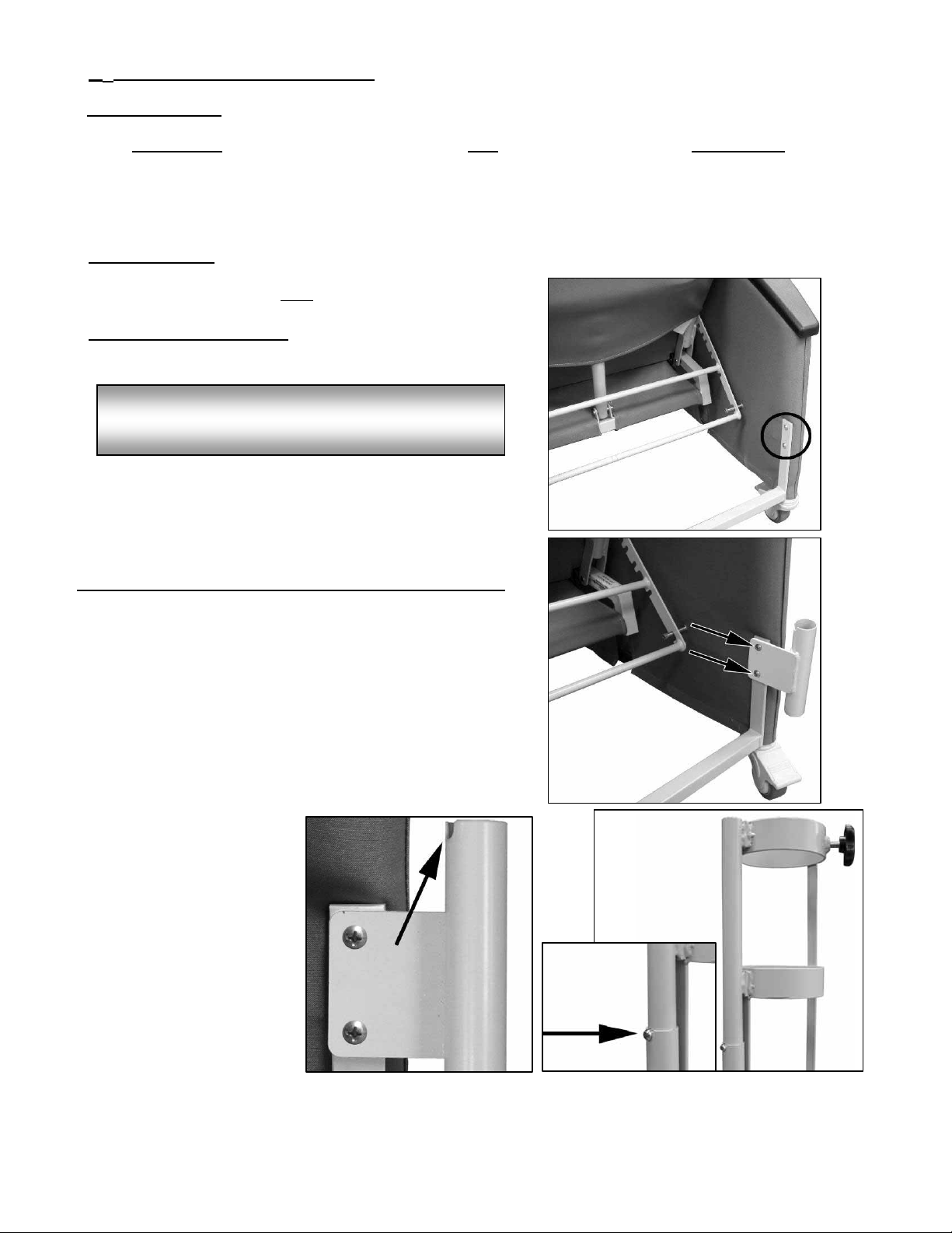
●Assembly Instructions
1. Locate the rear-right side of the chair. (FIG. 1)
Left & Right is determined – as if sitting in the chair
NOTE:
2. Using a Phillips-head screwdriver remove the 2 screws
from the rear brace. (FIG.1)
3. Line up the “O2 Mounting Bracket” with the holes in the
rear brace.
Be sure the notch in the mounting bracket is facing up. (FIG.3)
4. Re-intall the screws removed in STEP 2 and tighten to a snug
Fit. (FIG.2)
5. Insert O
holder into bracket until the silver snap-button
2
sits in the notch of the bracket. (FIG.4)
Page 2 of 5
FIG. 1
FIG. 2
FIG. 3
006321 REV. B Date 09-07-11 JWC
FIG. 4
Page 3

●O
Holder Assembly: 6550-6551-(Kit # 227615K), 6570-6571-(Kit # 227617K)
2
●Parts Included:
OXYGEN TANK HOLDER 1 250015
Description: Qty. Part Number
O2 U-BRACKET 1 227615
IV SPACER
(655 model ONLY) 1 227607
1” GRAY SQUARE CAP 2 700700
STAR KNOB 1 201215
1/4-20 x 2 3/4" PHILLIPS-HEAD SCREW 2 566571
1/4-20 NYLON LOCKNUT 2 566204
●Tools needed:
• Phillips Head Screwdriver
• 7/16” wrench (multiple size wrench included)
• Powered tools NOT recommended –
FIG. 1
●Assembly Instructions
1. Locate the REAR RIGHT-SIDE of the chair. (FIG.1)
Left & Right is determined – as if sitting
2. Insert the “Spacer” into the U-Bracket”
(FIG. 2) and place onto chair frame.
The “Spacer” is for the 655 model ONLY
and should be placed as shown. (FIG.2)
3. Insert the two screws through the holes in the
“U-Bracket”.
4. Screw on the nylon lock-nuts and, using the wrench
provided, tighten the lock-nuts to the bracket. (FIG.3)
5. Insert O
holder into bracket until the silver snap-button
2
sits in the notch of the bracket. (FIG.4)
NOTE:
in the chair
IMPORTANT:
FIG. 3
FIG. 2
FIG. 4
Page 3 of 5
006321 REV. B Date 09-07-11 JWC
Page 4

●O
Holder Assembly (Kit # 250010): 6940-6950
2
●Parts Included:
Description: Qty. Part Number
WELDED, OXYGEN TANK HOLDER 1 250015
O2 MOUNTING BRACKET 1 227613
STAR KNOB, MODIFIED, O2 HOLDER 1 201215
●Tools needed:
• ½” Wrench
• 3/16” Allen Wrench
• Power tools are NOT recommended
●Assembly Instructions
1. Locate the rear-right side of the chair. (FIG. 1)
Left & Right is determined – as if sitting
2. CAREFULLY place the chair on it’s side &
And open the swing arm all the way. (FIG.1)
3. Using a ½” wrench & a 3/16” allen wrench unscrew
the swing-arm hinge bolt. (FIG.2)
Some FORCE may need to be applied to the
allen wrench in order to loosen the hinge bolt
4. Take the loosened bolt out of the arm bracket, lift
upholstered swing-arm off of frame, and place on
floor.
5. Use a ½” wrench and REMOVE the bolts from the
hinge bracket. (FIG.3)
6. Line up the “O2 Mounting Bracket” with the holes in
the upholstered arm. Be sure the notch in the
mounting bracket is facing up. (FIG.3A)
7. Place the arm bracket on top of the “IV Bracket”
and re-install the 2 bolts using a ½” wrench. (FIG.3A)
8. Re-install the upholstered arm onto the chair frame
(FIG.4)
9. Insert O
holder into bracket until the silver snap-button
2
sits in the notch of the bracket. (FIG.5)
NOTE:
in the chair
NOTE:
FIG. 1
FIG. 5
FIG. 3
Page 4 of 5
FIG. 2
FIG. 3A
FIG. 4
006321 REV. B Date 09-07-11 JWC
Page 5

●O
Holder Assembly (Kit # 250040): 6980-6988-6990-6998
2
●Parts Included:
Description: Qty. Part Number
WELDED, OXYGEN TANK HOLDER, BLACK 1 250015B
O2 MOUNTING BRACKET, BLACK 1 227613B
STAR KNOB, MODIFIED, O2 HOLDER 1 201215
1/4-20 X 3/4 PHILLIPS-HEAD SCREW 2 566504
●Tools needed:
• Phillips-Head Screwdriver
• Power tools are NOT recommended
●Assembly Instructions
6. Locate the rear-right side of the chair. (FIG. 1)
Left & Right is determined – as if sitting in the chair
NOTE
7. Use (FIG.2) as reference to assist in locating the holes for the
IV bracket in the arm panel.
8. Use an awl or a Phillips-head screwdriver to pierce the vinyl
once you’ve located the bracket holes in the arm panel.
When piercing the vinyl be sure the tool DOES NOT
pierce through the outside of the arm panel.
WARNING
9. Line up the “O2 Mounting Bracket” with the holes in the
arm panel. (FIG.2)
Be sure the notch in the mounting bracket is facing up. (FIG.3)
10. Secure the IV bracket to the chair using the 2 phillips-head
screws provided. Tighten to a snug fit. (FIG.3)
11. Insert O
holder into bracket until the silver snap-button
2
sits in the notch of the bracket. (FIG.4)
FIG. 3
Page 5 of 5
FIG. 1
FIG. 2
FIG. 4
006321 REV. B Date 09-07-11 JWC
 Loading...