

Page 1
OWNERS
MANUAL
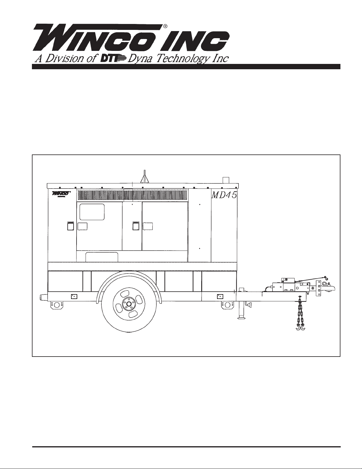
Mobile Diesel
Systems
MDS45
INSTALLATION AND OPERATION MANUAL
60706-154
Page 2

Read and understand all instructions in the manual
before starting and operating the generator set.
TABLE OF CONTENTS
USING THIS MANUAL
Congratulations on your choice of a Winco generator set.
You have selected a high-quality, precision-engineered
generator set designed and tested to give you years of
satisfactory portable service.
To get the best performance from your new engine
generator set, it is important that you carefully read and
follow the operating instructions in this manual.
Should you experience a problem please follow the
“Things To Check” near the end of this manual. The
warranty listed in this manual describes what you can
expect from WINCO should you need service assistance
in the future.
PROPER USE AND INSTALLATION
You must be sure your new engine generator set is:
* Properly serviced before starting
* Operated in a well ventilated area
* Exhaust gases are dispersed safely
* Wired by a qualified electrician
* Operated only for its designed purposes
* Used only by operators who understand its operation
* Properly maintained
COPY YOUR MODEL AND SERIAL NUMBER
BELOW FOR FUTURE REFERENCE.
No other WINCO generator has the same serial number
as yours. It is important that you record the number and
other vital information here, if you should ever need to
contact us on this unit it will help us to respond to your
needs faster.
PRODUCT SAFETY 1
SPECIFICATIONS 2
PREPARATION
UNPACKING 2
OIL REQUIREMENTS 2
FUEL REQUIREMENTS 2
COOLANT REQUIREMENTS 3
BATTERY CONNECTIONS 3
OPERATIONS
FRONT PANEL DESCRIPTION 3
RECEPTACLE AND BREAKERS 5
FULL POWER CONNECTIONS 5
ENGINE CONTROL MODULE 5
VOLTAGE REGULATOR 6
SELECTING THE CORRECT
VOLTAGE 7
START-UP CHECKLIST 7
ELECTRIC STARTING 7
REMOTE STARTING 8
CONNECTING THE LOADS 8
UNIT STORAGE 9
50 CYCLE OPERATION 9
MAINTENANCE 9
PREVENTIVE MAINTENANCE 9
WIRING DIAGRAMS
DC ELECTRICAL SCHEMATIC 10
RECEPTACLE PANEL 11
CIRCUIT BREAKER PANEL 11
CONTROL PANEL 12
CONTROL PANEL WIRING DETAIL 13
AC SCHEMATIC 14
AC WIRING DIAGRAM 15
WARRANTY 16
MODEL____________________________________
SERIAL NUMBER____________________________
PURCHASE DATE____________________________
DEALER___________________________________
Page i
Page 3

GUIDE TO PRODUCT SAFETY
This engine generator set has been designed and
manufactured to insure your personal safety. Improper
use can result in potential deadly hazards, from electrical
shock, exhaust gas asphyxiation, or fire. Please read all
safety instructions carefully before installation or use.
Keep these instructions handy for future reference. Take
special note and follow all warnings on the unit and in the
manuals.
************************************************************
CAUTION: Possible Damage to Equipment.
CAUTION notes indicate any condition or practice, which
if not strictly observed or remedied, could result in
damage or destruction of the equipment.
************************************************************
************************************************************
WARNING: Personal Danger.
WARNING notes indicate any condition or practice,
which if not strictly observed, could result in personal
injury or possible loss of life.
***********************************************************
1. ELECTRIC SHOCK - The output voltage present in
this equipment can cause a fatal electric shock. This
equipment must be operated by a responsible person.
A. Do not allow anyone to operate the generator without
proper instruction.
B. Guard against electric shock.
C. Avoid contact with live terminals or receptacles.
D. Use extreme care if operating this unit in rain or snow.
E. Use only three-prong grounded receptacles and
extension cords.
F. Be sure the unit is properly grounded to an external
ground rod driven into the earth.
2. FIRE HAZARD - Diesel fuel and other fuels always
present a hazard of possible explosion and/or fire.
A. Do not refuel when the engine is running or hot. Allow
the engine to cool at least two minutes before refueling.
B. Keep fuel containers out of reach of children.
C. Do not smoke or use open flame near the generator
set or fuel tank.
D. Keep a fire extinguisher nearby and know its proper
use. Fire extinguishers rated ABC by NFPA are appropriate.
E. Store fuel only in an approved container, and only in a
well-ventilated area.
4. NOISE HAZARD - Excessive noise is not only tiring,
but continual exposure can lead to loss of hearing.
A. Use hearing protection equipment when working
around this equipment for long periods of time.
B. Always operate with the housing doors closed to
reduce the operational noise level.
5. CLEANLINESS - Keep the generator and surrounding
area clean.
A. Remove all grease, ice, snow or materials that create
slippery conditions around the unit.
B. Remove any rags or other material that could create
potential fire hazards.
C. Carefully wipe up any gas or oil spills before starting
the unit.
D. Never allow leaves or other flammable material to
build up around the engine exhaust area.
6. SERVICING EQUIPMENT - All service, including the
installation or replacement of service parts, should be
performed only by a qualified technician.
A. Use only factory approved repair parts.
B. Do not work on this equipment when fatigued.
C. Never remove the protective guards, cover or receptacle panels while the engine is running.
D. Never wear neckties or other loose clothing that can
be caught in moving parts while you are servicing or
operating this equipment.
E. Use extreme caution when working on electrical
components. High output voltages from this equipment
can cause serious injury or death.
F. When servicing this unit always avoid hot mufflers,
exhaust manifolds, and engine parts. They all can cause
severe burns instantly.
G. Installing and wiring a standby generator is not a “do it
yourself” project. Consult a qualified, licensed electrician
or contractor. The installation must comply with all
national, state, and local codes.
7. LIFTING THE EQUIPMENT - When lifting always
make sure that the area under the equipment is kept
clear.
A. Be certain rigging is designed to lift unit safely.
B. Never attempt to lift the equipment unless you are
certain the lifting device has sufficient capacity.
C. Never allow the equipment to swing while suspended.
D. Be certain the supporting structure is adequate to
handle the load.
3. DEADLY EXHAUST GAS - Exhaust fumes from any
internal combustion engine contain carbon monoxide, an
odorless and deadly gas that must be mixed with fresh
air.
A. Operate only in well ventilated areas.
B. Never operate indoors.
C. Never operate the unit in such a way as to allow
exhaust gases to seep back into closed rooms (i.e.
through windows, walls or floors).
8. TOWING THE EQUIPMENT - When towing this
equipment always use a vehicle large enough for safe
operation.
A. Never tow without the safety chains secured.
B. Always use the proper size hitch ball on the vehicle.
C. Never attempt to tow with a vehicle that does not have
side mirrors installed.
Page 1
Page 4

SPECIFICATIONS
UNPACKING
GENERATOR SPECIFICATIONS
MDS45
KILOWATT 35 kW
KILOVOLT-AMPS (.8 PF)43.5 KVA
AMPERAGE 277/480 VOLT 3 PHASE 52 AMPS*
120/240 VOLT 3 PHASE 105 AMPS*
120/208 VOLT 3 PHASE 121 AMPS*
120/240 VOLT 1 PHASE 146 AMPS
*Based on .8 power factor at 130 degrees C.
Derate 3% per 1000 feet (305 meters) between 300 feet
(90 meters) and 7,500 feet (2,286 meters) above sea
level. Contact the factory for rating data for operation in
altitudes above 7,500 feet (2,286 meters).
GENERATOR RESISTANCE
MDS45
Main Stator 0.085 ohms
Main Rotor 3.2 ohms
Exciter Stator 0.35 ohms
Exciter Rotor 25 ohms
Exciter Voltage (F1-F2)
No Load 9.5 VDC
Full Load 36 VDC
Exciter Amperage (F1-F2)
No Load 0.4 Amps
Full Load 1.3 Amps
ENGINE SPECIFICATIONS
When receiving the unit, be sure to inspect it carefully for
freight loss or damage. Check the nameplate to be sure it
is what you ordered (proper kW, voltage, fuel, etc.). If
you have questions, contact your local authorized dealer.
If you see evidence of loss or damage at the time of
delivery, have the driver sign and describe the loss or
damage in the “memo of loss or damage” section on the
freight bill. Then contact the carrier to get instructions on
filing a claim.
When loss or damage is discovered after the equipment
is delivered, but not seen at the time of delivery, it is
referred to as “concealed damage.” Separate any damaged material and contact the carrier for proper procedures to file a “concealed damage” claim.
OIL REQUIREMENTS
This engine was filled at the factory. Before starting
check the oil level and ensure it is full. If not, fill to the
proper level with 15W-40 Cummins Premium Blue or
equivalent.
OIL QUANTITY US Qt. Liters
MDS45 8.0 7.5
FUEL REQUIREMENTS
See your engine operator's manual for complete type and
grade fuel information.
See Cummins Operation and Maintenance Manual for
complete engine specifications.
TRAILER/HOUSING
MDS45
Capacity 5000 lb.
Fuel Capacity 80 Gallons
Axles Single
Hitch Height Adjustable
Tires P225/75R-15
Tire Pressure 35 psi
Sound Attenuated ULTRA QUIET
Housing Housing Standard
PREPARATION
NOTE: This booklet covers the entire unit, EXCEPT THE
ENGINE. See the engine manufacturer’s operator
manual for specific maintenance and care information
regarding the engine. Read ALL instructions in the
manuals provided before attempting to operate the
generator set.
Filling the Fuel Tank
Standard Trailer - The standard trailer is equipped with a
single 80 gallon fuel tank. Use caution when filling the
tank not to overflow the tank into the trailer.
WARNING PERSONAL DANGER
Never refuel a running engine. Always stop the engine
and allow to cool before refueling.
Never allow the fuel tank to run completely empty, as air
may enter the fuel system making it necessary to bleed
the engine when restarting.
Page 2
Page 5
COOLANT REQUIREMENTS
The cooling system of this engine has been filled at the
factory with a 50% water and 50% ethylene-glycol
antifreeze and the proper amount of supplemental
coolant additives. This mixture provides protection to -37
degrees F.
The MDS45 requires a customer supplied 12 volt group
27 battery with minimum 675 CCA. A battery mounting kit
has been supplied loose with the unit. When connecting
the battery, ALWAYS CONNECT THE POSITIVE CABLE
FIRST and THE NEGATIVE CABLE LAST! Disconnecting
the battery is done in reverse, disconnecting the negative
cable first and then the positive cable.
When replenishing coolant or changing coolant refer to
your Cummins engine manual for the proper type and
mixture of water, antifreeze and supplemental coolant
additives.
WARNING: EQUIPMENT DAMAGE
Failure to properly follow Cummins requirements for
antifreeze and supplemental coolant additives can lead to
permanent damage to your engine cylinder liner walls.
COOLANT QUANTITY US Gal Liters
MDS45 6.67 25.3
BATTERY CONNECTION INSTRUCTIONS
WARNING! EQUIPMENT DAMAGE
FAILURE TO PUT THE ENGINE CONTROL SWITCH IN
THE ‘OFF’ POSITION PRIOR TO CONNECTING THE
BATTERY CABLE(S) MAY RESULT IN DAMAGE TO
THE ECM. (SOLID STATE ENGINE CONTROL MODULE).
WARNING - POTENTIAL BATTERY EXPLOSION
THIS UNIT USES A NEGATIVE GROUND. CONNECTING THE NEGATIVE CABLE FIRST MAKES THE
BATTERY POSITIVE TERMINAL HOT. CONNECTING
THE POSITIVE CABLE LAST MAY RESULT IN ACCIDENTAL SHORT CIRCUIT OF THE POSITIVE BATTERY TERMINAL TO ANY OF THE SURROUNDING
METAL SURFACES. (I.E. DROPPING A TOOL,
WRENCH SWING ETC.) USE EXTREME CAUTION
WHENEVER MAKING OR BREAKING THE BATTERY
CONNECTIONS AND FOLLOW THE CORRECT
SEQUENCE CAREFULLY.
NEVER ATTEMPT TO JUMP START THIS ENGINE.
If the battery should accidentally become discharged
disconnect the battery cables and recharge the battery
before attempting to start the unit. Boost/jump starting
this unit improperly will result in PERMANENT DAMAGE
TO THE ENGINE CONTROL MODULE (ECM).
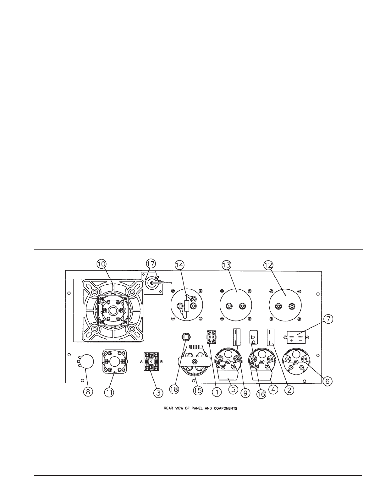
DESCRIPTION AND IDENTIFICATION
A. FRONT PANEL
1. Starting Controls (1)- This unit is equipped for
manual or automatic start. A three position switch controls
the engine starting.
Page 3
a. “Off” - This switch position stops the engine and
disconnects the power from the engine control module. It
is intended to safely allow service and maintenance
checks on the engine
b. “RUN” - This switch position engages the start
circuitry in the engine control panel. The engine control
module goes into a 12 second start delay and then the
Page 6
starter is engaged. The engine control module in the
control panel will disengage the starter when the unit
starts and engage the engine monitoring sensors.
c. “AUTO” - This switch position is used when the
MDS45 is used in a standby mode. With the switch in this
position a remote contact (i.e. Automatic Transfer Switch)
can be closed to engage the start circuitry. A terminal
block has been provided behind the customer connection
door for you to wire your remote contact into. This remote
contact must close to provide a path between the start
wire and battery negative.
2. DC Control Circuit Breaker (DCCB) (2)- The 15
amp DC Circuit Breaker protects the engine controller and
wiring harness against faults in wiring or control equipment. The DCCB also prevents a discharge of the battery
due to a circuit fault.
3. Emergency Stop Switch (3)- When depressed this
switch will disconnect all the 12 volt power to the engine
control panel shutting the engine down. The lamp in the
emergency stop switch will light up when the switch is
depressed showing that the power to the panel has been
disconnected.
b. Field circuit breaker (FCB) (9)- Protects voltage
regulator and exciter field in the event of a load short
circuit or equipment malfunction.
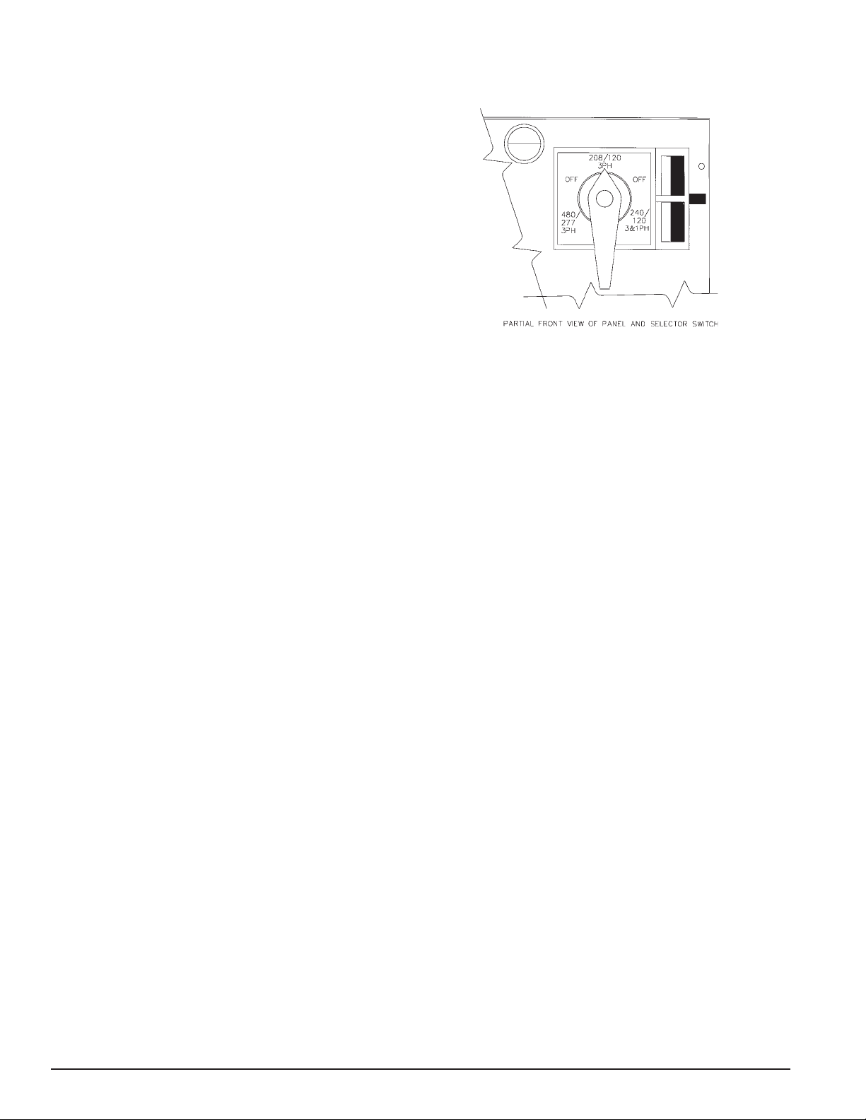
c. Voltage selector power switch (10)- This heavy
duty three position switch allows the operator to quickly
and safely reconnect the 12 lead generator to any one of
three output voltages. Once the output voltage is selected, the switch may be locked to prevent it from
accidentally being changed during operation. Three
output voltage combinations are available with this
selector switch:
4. Engine Instruments
a. Oil pressure monitor gauge (OPG) (4)- The oil
pressure gauge is mounted on the front control panel and
indicates the engine oil pressure. The gauge serves a
dual function. In addition to displaying the oil pressure it
also provides the shutdown signal to the engine control
module if the pressure should drop too low. The shutdown signal is factory preset at 15 psi (103 kPa/m sq).
b. Coolant temperature monitor gauge (CTG) (5)-
The coolant temperature gauge indicates engine coolant
temperature. The gauge serves a dual function. In
addition to displaying the water temperature it also
provides the shutdown signal to the engine control
module if the water temperature gets too high. The
shutdown signal is preset to operate at 225 f (407 k)
c. Battery Voltage Meter (6)- This DC voltmeter
monitors the VOLTAGE of the battery under static (at
rest) conditions, and under cranking and charging
conditions. The voltmeter indicates not only the condition
of the charging system, but also indicates the battery
reserve under cranking load in cold weather.
d. Running Time Meter (7)- This DC meter records
the total hours the engine has run.
5. AC Generator Controls
a. Voltage adjust rheostat (8)- Controls the output
voltage of the generator by varying voltage regulators
reference voltage.
1. 120/240 Three Phase* (series Delta
configuration)
2. 120/208 Three Phase (Low or Parallel “WYE”
configuration)
3. 277/480 Three Phase (High or series “WYE”
configuration)
*This selector position is also used for single phase 120/
240 output by using only the L1 and L2 leads. The three
phase L3 output lead is the “wild” leg in the Delta configuration.
6. AC Generator Instruments
a. VM/AM Selector Switch (11)- This selector switch
allows you to check the amperage being drawn from
each generator leg and your line to line voltage.
b. AC Voltmeter (VM) (12)- Monitors generator
output line to line voltage, for all voltage operations.
c. AC Ammeter (AM) (13)- Monitors the amperage
that is being drawn from each leg of the generator.
d. AC Frequency Meter (14)- Monitors the generator
frequency.
7. Warning Light Cluster (15)- This light cluster
contains the indicator lamps for the four engine shutdowns controlled by the engine control module. The
lamps will stay lit after a shutdown until the selector
switch has been moved to the off position. All the shutdowns are reset when the selector switch is turned off or
the DC circuit breaker is turned off.
Page 4
Page 7

a. Low Oil Pressure Lamp (LOP) - Indicates that the
unit did not maintain a minimum oil pressure of 15 psi.
C. FULL POWER LOAD CONNECTIONS and
BREAKERS
b. High Water Temperature Lamp (HWT) - Indicates
the coolant temperature in the engine exceeded upper
coolant temperature limits.
c. Overspeed Lamp (OS) - Indicates the engine
speed exceeded the allowable speed limit while operating. An OS light may also indicate that the ECM has lost
its frequency sensing signal (from the engine alternator)
during the last run period.
d. Overcrank Lamp (OC) - Indicates the engine
tried to start and went through five (5) twelve (12) second
crank cycles without starting. Before attempting to restart
the unit, first investigate why it didn’t start.
8. Lamp Test Switch (16)- The lights can be tested by
pressing the lamp test switch. When depressed all four
lights will come on. As soon as the switch is released the
light will go out.
9. Panel Light (17)(18)- A panel light is provided for
your convenience. It is activated by the panel light switch.
B. RECEPTACLES and CIRCUIT
BREAKERS
1. 120 Volt 20 Amp Ground Fault Interrupter Duplex.
This duplex receptacle is protected by a 20 Amp circuit
breaker mounted just above the duplex. With the “T” slot
design both 15 and 20 amp 120 volt cords can be
plugged in.
2. 120 Volt 20 Amp 3 wire twist lock, NEMA Spec L5-
20. This twistlock receptacle is also protected by a 20
Amp circuit breaker. This receptacle is wired in series
with the GFCI receptacle which provides it with GFCI
protection.
3. 240 Volt 20 Amp 3 wire twist lock, NEMA Spec L6-
20. This twistlock receptacle is protected by a two pole
240 volt circuit breaker.
4. 120/240 Volt 50 Amp 4 wire twistlock. This receptacle
is rated for dual voltage, 120 or 240 volt use. It is a four
wire receptacle, with a center grounding pin. Four wire
drop cords plugged into this receptacle may be split into
120 volt receptacles at a distribution box. This receptacle
is protected by a two pole 50 amp circuit breaker mounted
just above it. THIS RECEPTACLE UTILIZES A SPECIAL
HUBBELL PLUG.(HUBBELL PART NUMBER “CS
6365”.)
This Mobile Diesel Power System is equipped with both
high voltage (480) and low voltage (208/240) main line
breakers. The breakers are interlocked with a lockable
bar to insure that only one breaker can be turned on at a
time.
A full power output terminal block is provided. This
terminal block is located below the main power breakers
and is accessible through the access door located just
below the main line breakers. If this access door is
opened with the unit running a safety switch will disable
the 12 volt system shutting the unit down. This door must
remain closed and latched at all times during normal
operations.
DANGER: PERSONAL INJURY
This unit will start as soon as the door is closed if the
start switch is in the run position. Do not use the switch
on this door to shutdown a unit to connect to the full load
terminal block , this is a safety switch only.
D. ENGINE CONTROL MODULE (ECM)
The ECM is a microprocessor based module that controls the complete unit. It monitors all the engine safety
sensors such as oil pressure, water temperature,
overspeed, and overcrank and shuts the unit down
should any one of the sensor circuits show a fault.
1. Control Switch Inputs
The following front panel controls and instruments are
wired into the microprocessor through the ECM terminal
blocks.
a. Run-Off-Auto switch:
1. “Run” - This is your local operation position.
In this position the engine will start immediately.
2. “Off” - position prevents unit operation by
disconnecting all power to the ECM.
3. “Auto” - position powers up the ECM in a
standby mode. A remote switch closure is
required to activate the start circuits.
2. Safety Inputs:
a. Low oil pressure shutdown -(LOP)- Monitoring of
oil pressure begins 12 seconds after the unit starts, and
remains in effect until unit is shut down by normal control
circuits (except as noted in “loss of frequency input”
below). The ‘LOP’ signal is derived from an oil pressure
gauge mounted in the engine control panel.
Page 5
Page 8

b. High water temperature shutdown -(HWT)- The
engine coolant sensor temperature monitoring begins
immediately with the start signal. If water temperature is
excessive at time of start, (i.e. heat soak after shutdown),
the unit is still permitted to start. The ‘HWT’ condition is
permitted to exist for up to 60 seconds after the unit
initially starts before a shutdown WITH ALARM occurs. If
the excessive water temperature condition is corrected
within the initial 60 second period, the ‘HWT’ circuit
begins normal monitoring of the engine temperature and
the ‘safety shutdown’ circuit is reactivated. The ‘HWT’
signal is derived from a temperature gauge mounted in
the engine control panel.
c. Overspeed adjustment -(OS)- Overspeed protection is provided by a frequency sensing network within the
controller. The trip point of the frequency network is
adjustable via a rheostat located in the center of the
controller. The adjustment is accessed through the small
hole in the center of the engine control module.
NOTE: Use a plastic or non-metallic screwdriver when
making any adjustment to the overspeed. Clockwise
(CW) rotation increases the trip frequency, and thereby
raises the shutdown speed. The frequency input is
obtained from the engine battery charging alternator.
d. Overcrank -(OC)- The MDS45 is designed to use
cycle cranking. This feature provides a series of five
cranking cycles lasting 12 seconds with a 12 second rest
period between each. Failure of the engine to start by
the end of the fifth crank period results in an “overcrank”
shutdown and alarm indication.
3. Cranking Disconnect Signal
TROUBLE SHOOTING HINT: This is of particular note
since the tendency is to pursue only overspeed faults.
The overspeed signal source (battery charging alternator)
is a key component in this system and must be checked
out thoroughly whenever an “OS” shutdown occurs.
Please note: The controller does not provide protection
against loss of signal during start-up. A shutdown with
alarm due to any of the above conditions will prevent any
subsequent operation of the generator set. The control
switch on the control panel must be momentarily placed
in the “off” position to reset.
E. VOLT/HERTZ VOLTAGE REGULATOR
The purpose of the voltage regulator is to maintain the
voltage output of the Generator Set within a specified
percentage of its rated output from no load to full load.
The voltage regulator controls the voltage output of the
main generator by regulating the amount of current
delivered to the exciter field.
1. Location -Access to the voltage regulator assembly
is gained by removing the control panel access door
located through the left rear housing door.
2. Description - The Basler model VR63-4C voltage
regulator is a completely encapsulated unit. The regulator
controls the DC exciter field voltage on brushless generators to regulate the output voltage. Regulation is provided
by sensing the generator output voltage, converting it to
a DC signal and comparing the signal to a reference
voltage signal. An error signal is developed and used to
control the DC field power in order to maintain a constant
generator output.
The cranking disconnect signal is obtained from the
frequency sensing network within the controller. The trip
point of the crank disconnect is not directly adjustable but
is a percentage of the overspeed adjustment.
4. E.C.M. - Program Notes
a. Loss of frequency input - In the event the input
frequency goes to zero (engine runs out of fuel, battery
charging alternator fails, etc.), the LOP shutdown circuit
is by-passed, and a 12 second wait period is initiated. If
frequency returns within this time period, LOP monitoring
resumes and operation continues normally. If frequency
has not returned at the end of this time period, the engine
oil pressure status is observed to determine whether the
engine is actually running or stopped. If the engine has
stopped (i.e.- air in fuel, etc., the unit is shut down with
an “overspeed” indication and alarm.
b. “Overspeed” indicator light can mean a loss of
control signal during the previous run period (i.e.- bat.
charging alternator belt broken).
3. Operation of Voltage Regulator - The voltage
regulator has been installed in the Mobile Diesel Generator set and tested at the factory prior to shipment. No
additional set-up is required when changing from one
voltage to another. The only adjustment required is to
fine tune the exact voltage you want using the voltage
adjustment rheostat located on the front panel. The
adjustment range is 10% of the nominal voltage.
Some minor changes must be made for 50 cycle operation. Refer to 50 Hz operation later in this section for setup procedures.
a. During periods of operation at reduced speed use
the field circuit breaker to remove the power from the
regulator.
b. If the exciter field voltage exceeds 95 VDC, the
regulator senses over excitation and automatically
removes the field current after a time delay. This time
delay is inversely proportional to the magnitude of the
detected over voltage condition. At approximately 140
VDC, the field voltage is removed instantaneously.
Page 6
Page 9

Upon detection of over excitation and the resulting field
voltage shutdown, the regulator will not reset or return to
an operational condition until the generator output voltage
drops to less than 6 VAC for ten seconds (minimum). TO
ACCOMPLISH THIS ON A MOBILE DIESEL GENERATOR SET THE FIELD CIRCUIT BREAKER MUST BE
TURNED OFF FOR TEN SECONDS.
OPERATING THE UNIT
A. SELECTING THE CORRECT VOLTAGE
A variety of voltages are available from the three position
selector switch. The three basic connection patterns are,
Delta (120/240), Low or Parallel WYE (120/208), and
High WYE (277/480). Single phase 120/240 is available
with the switch in the 120/240 (Delta) position.
3. 277/480 Three Phase (High/Series WYE configura-
tion) This configuration will produce the following line-to-
line and line-to-neutral outputs. The 120 volt receptacles
are the only panel receptacles powered in this voltage
configuration. They are limited to 12 Amps total.
L1 - L2 - L3 480 Volts three phase
L1 - L2 480 Volts single phase
L2 - L3 480 Volts single phase
L1 - L3 480 Volts single phase
L1 - N 277 Volts
L2 - N 277 Volts
L3 - N 277 Volts
After you have selected the correct voltage for your
application and locked the selector switch, do the same
with the main line circuit breakers. Be sure to secure the
lock bar in place. This will prevent the incorrect breaker
from being turned on.
Before connecting this unit to a distribution panel or any
other loads, be sure you have the selector switch set for
the right voltage and locked. If you have any doubts as to
the voltage in your area compare your incoming power or
load name plates to the voltage table below.
1. 120/240 Three Phase* (Delta/Series configuration) This configuration will produce the following line-to-line
and line-to-neutral voltage. In this selector switch position, all of the receptacles on the front panel are powered.
L1 - L2 - L3 240 Volts three phase
L1 - L2 240 Volts single phase
L2 - L3 240 Volts single phase
L1 - L3 240 Volts single phase
L1 - N 120 Volts
L2 - N 120 Volts
L3 - N 208 Volts
*This selector position is also used for single phase 120/
240 output, using only the L1 and L2 leads. The L3 three
phase output lead is the “wild” leg in the delta configuration and is used only for three phase loads.
B. STARTUP CHECKLIST
Before initial start up and each subsequent start com-
plete the following checklist:
1. Check oil level, refill with proper grade oil.
2. Check coolant level, refill with proper mixture of
coolant. See engine manual.
3. Check for loose bolts or hardware.
4. Check tire pressure. (35 psi)
5. Trailer level to within 15 degrees.
6. Battery securely fastened, connection clean and
tight, and proper fluid level.
7. Fuel tank filled with the proper grade of diesel
fuel.
8. Check the fan belt for tightness and excessive
wear.
9. Check hoses and clamps for leakage.
10. Check the air cleaner indicator. Service only
when indicated. Do not over-service.
11. Clean out dust cup on the air cleaner.
C. ELECTRIC STARTING (Normal portable use)
2. 120/208 Three Phase (Low/Parallel WYE configuration) This configuration will produce the following line-toline and line-to-neutral voltage. Use of this selector
switch position allows utilization of the 120 volt receptacle
only. The 240 volt receptacles cannot be used as the
voltage at them will be 208 volts, the line to line voltage.
L1 - L2 - L3 208 Volts three phase
L1 - L2 208 Volts single phase
L2 - L3 208 Volts single phase
L1 - L3 208 Volts single phase
L1 - N 120 Volts
L2 - N 120 Volts
L3 - N 120 Volts
Page 7
CAUTION: EQUIPMENT DAMAGE
DO NOT ATTEMPT TO JUMP/BOOST START THIS
UNIT. TO DO SO MAY DAMAGE THE ELECTRONIC
MICROPROCESSOR IN THE ENGINE CONTROL.
TURN THE DC BREAKER “OFF” AND RECHARGE
THE BATTERY WITH A BATTERY CHARGER.
1. Select the desired voltage on the voltage selector
switch and lock in place.
2. Turn off both main line circuit breakers.
3. Turn the control switch to the “run” position. In this
position the unit will go into an automatic start routine.
The control goes into a start delay and the starter will
engage 12 seconds later. The starter will automatically
disengage as the engine comes up to proper operating
speed.
Page 10

4. After the engine is running at proper speed, adjust the
voltage to the desired level using the external voltage
rheostat.
5. Turn on the proper main line breaker (either high or
low voltage) and padlock the lock bar to prevent the
incorrect breaker from being turned on.
D. REMOTE STARTING AND CONNECTION
(Standby applications)
1. Complete the manual starting procedure above to
insure the system is set up properly.
2. Insure the start switch is in the “off” position during
installation of the remote start connections.
3. Locate the remote start terminal block. This terminal
block is located next to the full power connections,
behind the access door at the bottom of the control
panel.
4. Locate the remote start terminals in your remote
automatic transfer switch (ATS). The ATS terminal block
and wire numbers will vary with each ATS manufacturer.
The MDS45 requires a contact closure for start.
WARNING: EQUIPMENT DAMAGE
THE REMOTE “SIGNAL” MUST BE A “DRY” (NONPOWERED) CONTACT CLOSURE. USING A POWER
CONTACT WILL CAUSE PERMANENT DAMAGE TO
THE ENGINE CONTROL MODULE.
5. For most installations sixteen gauge wire is sufficient
to handle the control signal. On extremely long runs
increase wire size to minimize voltage drop.
10. For isolated neutral operation remove the jumper wire
between the ground lug and neutral connection block.
11. Ground the Mobile Diesel Generator set using an 8 ft
copper ground rod or other approved grounding system.
Connect #4 Awg Copper cable from the ground lug on
the generator to the ground rod.
12. Set the selector switch on the transfer switch to the
“off” position.
13. Move the start switch on the MDS45 to the “RUN”
position. The generator set will now start.
14. Check the voltage at the transfer switch. Verify that
it matches the incoming power line voltage line-to-line
and line-to-neutral on each leg.
15. Check the three phase rotation pattern. Insure that
you have the same rotation, with both the generator and
the normal power source.
16. Move the start switch on the MDS45 to the “STOP”
position. Let the unit stop and then move the switch to
the “AUTO” position. This is the normal position for the
switch to be in for automatic start operations.
17. Move the selector switch on the transfer switch to the
“AUTO” position. This is the normal position for the
switch to be in for automatic start operation.
18. Use the test switch on the transfer switch or shut off
the incoming power to test the complete system. The
MDS45 should start up and the transfer switch should
transfer the load to the generator.
6. Locate the neutral and full power output load connection terminal on the generator.
7. Locate and identify the “neutral” and “generator”
connections in the automatic transfer switch.
8. Connect the load block to the transfer switch using
the proper wire sizes. Refer to the National Electric
Code Handbook (NFPA 70) for proper wire type and
sizing. Use Table 310-16 for wiring run through conduit
and table 310-17 for free air wiring.
Use extreme caution when installing the delta voltage
pattern. One power leg of this 3 phase pattern produces
208 volts measured from line to neutral. Be sure to
match the location of the generator wild leg to the location of the wild leg on the incoming power service.
Failure to do so will cause equipment damage to any 120
volt load incorrectly connected to this line.
9. Connect the neutral to the transfer switch using the
same wire size.
19. Compare the amperage reading from each leg on the
generator and insure that none of the legs is exceeding
the nameplate rating on the generator.
20. Upon completion of the test, leave all control mode
switches in the “AUTO” position.
21. The system is now ready to start and power the
loads should the power fail.
E. CONNECTING THE LOADS
There are two ways the loads may be connected to a
Mobile Diesel Generator.
1. FRONT PANEL - A variety of receptacles have been
provided for your convenience on the front panel. The
120 volt receptacles are powered when the voltage
selector switch is in the 120/240 or 120/208 volt position.
The 240 volt receptacles (although powered in both
positions) are only usable in the 120/240 volt position. In
the 120/208 volt position the 240 volt receptacles have
only 208 volts at them.
Page 8
Page 11

2. FULL POWER LOAD CONNECTION TERMINAL
BLOCK - For remote connections and connecting load
distribution boxes, heavy duty terminal blocks have been
provided. These terminal blocks are located on the rear
of the unit just below the main line circuit breakers. The
neutral and ground are connected together at this panel.
For use with an isolated neutral, remove the jumper strap
between the neutral connection block and the ground lug.
This will isolate the neutral from the ground and allow you
single point grounding at a distribution panel. When using
these terminal blocks be sure to use wire rated large
enough to carry your full load or the full rated load of the
generator.
3. GROUNDING THE UNIT - To comply with current
safety standards this generator set must be properly
grounded. Ground the Mobile Diesel Generator set by
driving an 8 ft copper ground rod into the earth. Then
connect a #4 AWG ground cable from the grounding lug
on the generator to the ground rod.
F. UNIT STORAGE
Certain precautions must be taken if a Mobile Diesel
Generator set is to be stored for a long period of time.
The unit must be stored in a dry location to prevent the
generator winding from drawing moisture. The unit should
also be thoroughly cleaned prior to storage.
For engine storage procedures consult your local
Cummins engine dealer. They have certain procedures
that must be followed in order to prevent engine damage,
i.e. cylinder rust and injector deterioration.
MAINTENANCE
The ultimate aim of a preventive maintenance program is
to maintain the equipment in optimum condition, either in
service or ready for service, for the maximum amount of
time during the useful life of the equipment. The detection of faults before they develop into major sources of
difficulty will decrease the incidence of repair. To this
end, a regular schedule of cleaning and inspection will go
far toward assuring trouble-free operation. Personnel
responsible for maintenance should set up a schedule for
inspection, and cleaning at intervals calculated to keep
the equipment in good condition. In making up a schedule, keep the following in mind:
A. New equipment must be carefully monitored until
extended operation has demonstrated that it is performing satisfactorily.
B. Old equipment requires more frequent inspection
(and possibly servicing) than similar equipment that has
seen less service.
C. Time spent in cleaning, inspecting and correcting
minor defects before they become major troubles means
time saved in overhaul and repair.
PREVENTIVE MAINTENANCE
A. Daily Maintenance Checklist
** Oil level is between the “L” low mark and the “H” high
mark on the dipstick
** Fuel tank full of proper grade of diesel fuel
50 CYCLE (HZ) OPERATION
With a couple of minor changes these Mobile Diesel
Generators are capable of producing 50 Hz power. Two
changes must be made:
A. The engine must be reduced to 1500 RPM governed
speed. Consult your local Cummins Service Center for
the proper procedure for reducing the engine speed and
setting up the governor to operate at 1500 RPM.
B. The automatic volt/hertz regulator must also be reset
to operate at 50 HZ instead of the standard 60 HZ. This
is done by cutting the two leads marked HZ that come
out of the regulator. This will change the regulator for 60
HZ operation to 50 HZ operation. If it should become
necessary to change it back to 60 HZ, you would need to
splice the leads together again.
** Water and sediment drained from water separator
** Radiator filled with the proper coolant mixture
** Check air cleaner service indicator. Change the filter
element when the red indicator flag is at the raised
position
** Inspect for any fluid leaks
** Look for any loose or damaged parts
** Check belts for cracks or frays
** Check trailer hitch and safety chains for fitness
** Check tires for proper pressure
** Check battery for proper fluid level
** Check the generator control panel for loose or dam-
aged parts
** Check the unit for general appearance and cleanliness
Page 9
Page 12

DC ELECTRICAL SCHEMATIC
Page 10
Page 13

RECEPTACLE PANEL WIRING
CIRCUIT BREAKER PANEL
Page 11
Page 14

WIRING DIAGRAM
CONTROL PANEL
Page 12
Page 15

CONTROL PANEL
WIRING DETAIL
Page 13
Page 16

AC SCHEMATIC
Page 14
Page 17

AC WIRING DIAGRAM
Page 15
Page 18

WINCO, INC.
12 Month Limited Warranty
WINCO, Incorporated warrants to the original purchaser for 12 months that goods manufactured or supplied by it will be free from defects in workmanship and material, provided such
goods are installed, operated and maintained in accordance with WINCO written instructions.
WINCO’s sole liability, and Purchaser’s sole remedy for a failure under this warranty, shall
be limited to the repair of the product. At WINCO’s option, material found to be defective in
material or workmanship under normal use and service will be repaired or replaced. For
warranty service, return the product within 12 months from the date of purchase, transportation charges prepaid, to your nearest WINCO Authorized Service Center or to WINCO, Inc.
at Le Center Minnesota.
THERE IS NO OTHER EXPRESS WARRANTY.
To the extent permitted by law, any and all warranties, including those of merchantability and
fitness for a particular purpose, are limited to 12 months from date of purchase. In no event
is WINCO liable for incidental or consequential damages.
Note: Some states do not allow limitation on the duration of implied warranty and some
states do no allow the exclusion or limitation of incidental or consequential damages, so the
above limitations may not apply in every instance. This warranty gives you specific legal
rights which may vary from state to state.
WINCO reserves the right to change or improve its products without incurring any obligations
to make such changes or improvement on products purchased previously.
EXCLUSIONS:
WINCO does not warrant engines, batteries, or other component parts that are warranted by
their respective manufacturers.
WINCO does not warrant modifications or alterations which were not made by the WINCO,
Inc.
WINCO does not warrant products which have been subjected to misuse and/or negligence
or have been involved in an accident.
60706-154 - 2204-00
225 South Cordova Avenue
Le Center, Minnesota 56057
1-507-357-6821
 Loading...