

Page 1
INSTALLATION INSTRUCTIONS
LOW PRESSURE FUEL SOLENOID KIT
FOR MODELS:
HPS6000HE/I, HPS9000VE/E
** For older version HPS gen-set instruction sheets go to
www.wincogen.com/service support/winco downloads/portable generators. **
3
1
4
5
6
2
7
8
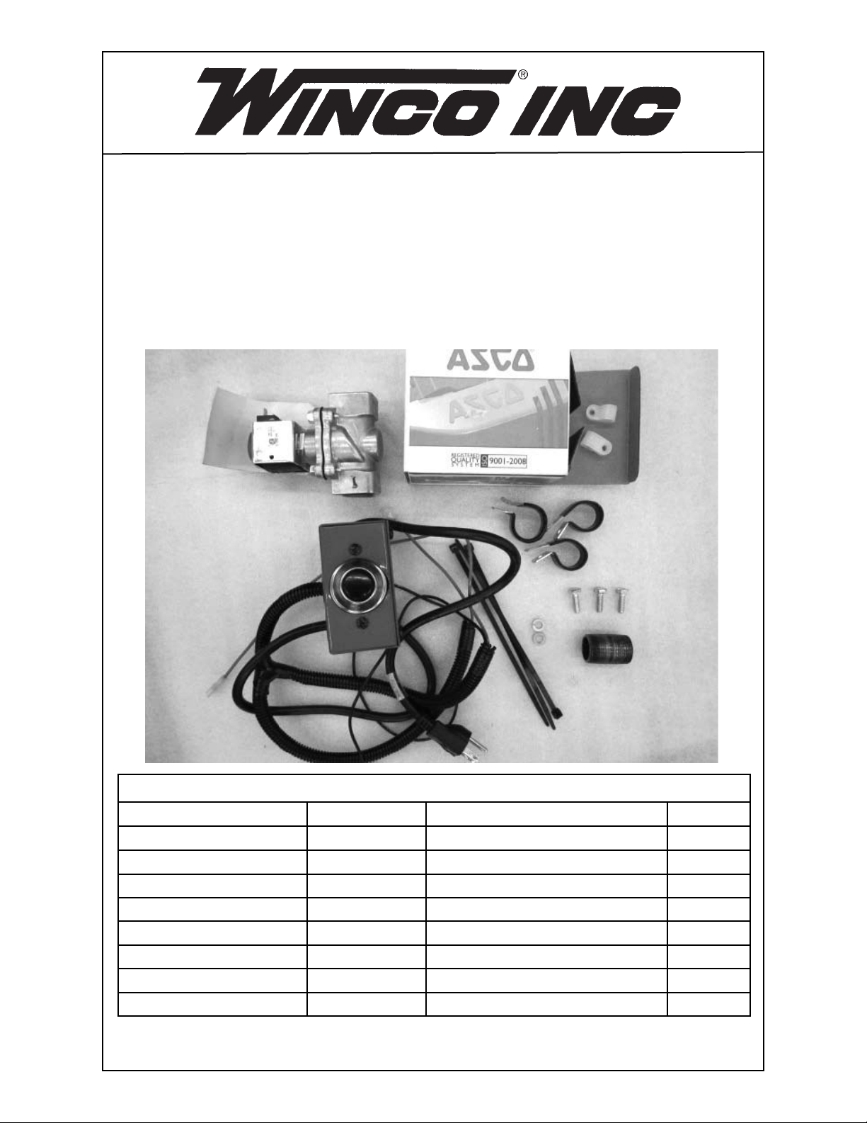
COMPONENT LIST
REF. # PART # DESCRIPTION QTY.
1 42942-000 Gas Solenoid Valve 1
2 64856-006 Control Box Assembly 1
3 48039-006 Nylon Clamp 2*
4 97391-003 Tube Clamp 3**
5 479-000 Lock Washer 2
6 466-000 1/4” X 20 X 3/4” Bolt 3
7 54074-006 Pipe Nipple 1
8 49975-011 Cable Tie 3
* Not used on HPS6000HE/I and HPS9000VE/E models
** Used on HPS models prior to 2013.
113256-00 64854-005I
Page 2
STEP 1
Install control box assembly (ref. 2) onto the frame of the gen-set (battery side) us-
•
ing 2 bolts (ref. 6) and lock washers (ref. 5).
•
Tighten with a 1/2” end wrench.
Run the cord to the rear of the generator and plug into one of the receptacles.
•
STEP 2 HPS6000HE/I
Thread the pipe nipple (ref. 7) onto the 90° elbow using pipe sealant.
•
•
Thread the gas solenoid valve (ref. 1) onto the pipe nipple using pipe sealant.
Make sure the solenoid end marked “OUT” is toward the generator and the
•
solenoid end marked “IN” is toward the supply line.
Tighten with a pipe wrench.
•
•
Connect wires labeled 1 & 21 from control box harness to the solenoid. Polarity
does not matter.
7
213256-00 64854-005I
Page 3

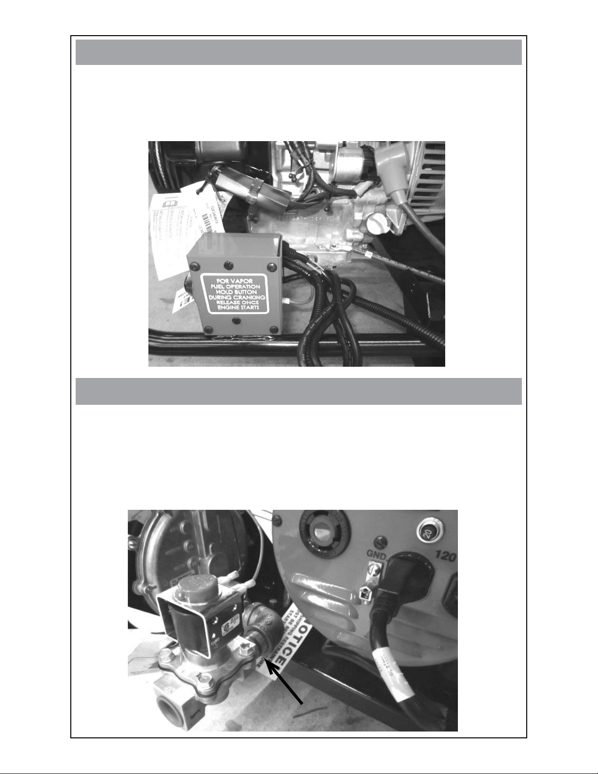
STEP 2 HPS9000VE/E
Remove the bolt (A) holding the demand regulator down and rotate the demand
•
regulator. This allows for turning of the pipe nipple and solenoid.
Thread the pipe nipple (ref. 7) onto the 90° elbow using pipe sealant.
•
•
Thread the gas solenoid valve (ref. 1) onto the pipe nipple using pipe sealant.
Make sure the solenoid end marked “OUT” is toward the generator and the
•
solenoid end marked “IN” is toward the supply line.
Tighten with a pipe wrench.
•
Replace demand regulator bolt.
•
•
Connect wires labeled 1 & 21 from control box harness to the solenoid. Polarity
does not matter.
A
STEP 3 HPS6000HE/I
Take battery positive cable loose from starter solenoid (A). Route RED wire # 2
•
through the rubber cable protector (B) and re-tighten starter solenoid nut (C).
•
Take battery negative cable loose from engine base (D). Place BLACK wire # 1
under the bolt and re-attach battery negative cable to engine base.
C
A
B
D
313256-00 64854-005I
Page 4

STEP 3 HPS9000VE/E
Take battery positive cable loose from starter solenoid (A). Route RED wire # 2
•
through the rubber cable protector (B) and re-tighten starter solenoid nut (C).
•
Take battery negative cable loose from engine base (D). Place BLACK wire # 1
under the bolt and re-attach battery negative cable to engine base.
C
A
B
D
STEP 4
Using the cable ties (ref. 8) provided, neatly tie excess wire loom, wire and power
•
cable to prevent rubbing on the engine. HPS9000VE/E shown below.
TO START: Hold down control box button, turn key, engine will start. Once unit
•
generates power (about 1 second) release button.
8
Winco Inc.
Service Dept.
507-357-6831
413256-00 64854-005I
 Loading...