

Page 1
Operator Manual
Auto St art Generator Controller
Mechanical Diesel or Gaseous Engines
Part Number: GM100 14 (102-2003)
Version 1.0
______________________________________________________________________________________________________________________________________
Copyright © Controls, Inc.
P.O. Box 368 • Sharon Center, OH 44274
Phone 330.239.4345 • Fax 330.239.2845 • www.controlsinc.com
Page 2

Basic Controller Operation
1) Manual Start
a. Place selector switch in the RUN position.
b. Controller will begin start sequence.
• Preheat (if programmed).
• Crank and fuel systems are energized.
• Control will crank disconnect
automatically once the engine has
been started.
2) Manual Stop
a. Place selector switch in the OFF position.
• Power to fuel solenoid will be turned
off.
3) Automatic Operation
a. Place selector switch in the AUTO position.
b. Close the “REMOTE START” circuit to ground
for engine start.
• Preheat (if programmed).
• Crank and Fuel energized.
• Control will crank disconnect
automatically once the engine has
been started.
c. Open the “REMOTE START” circuit to stop the
engine.
1
Page 3

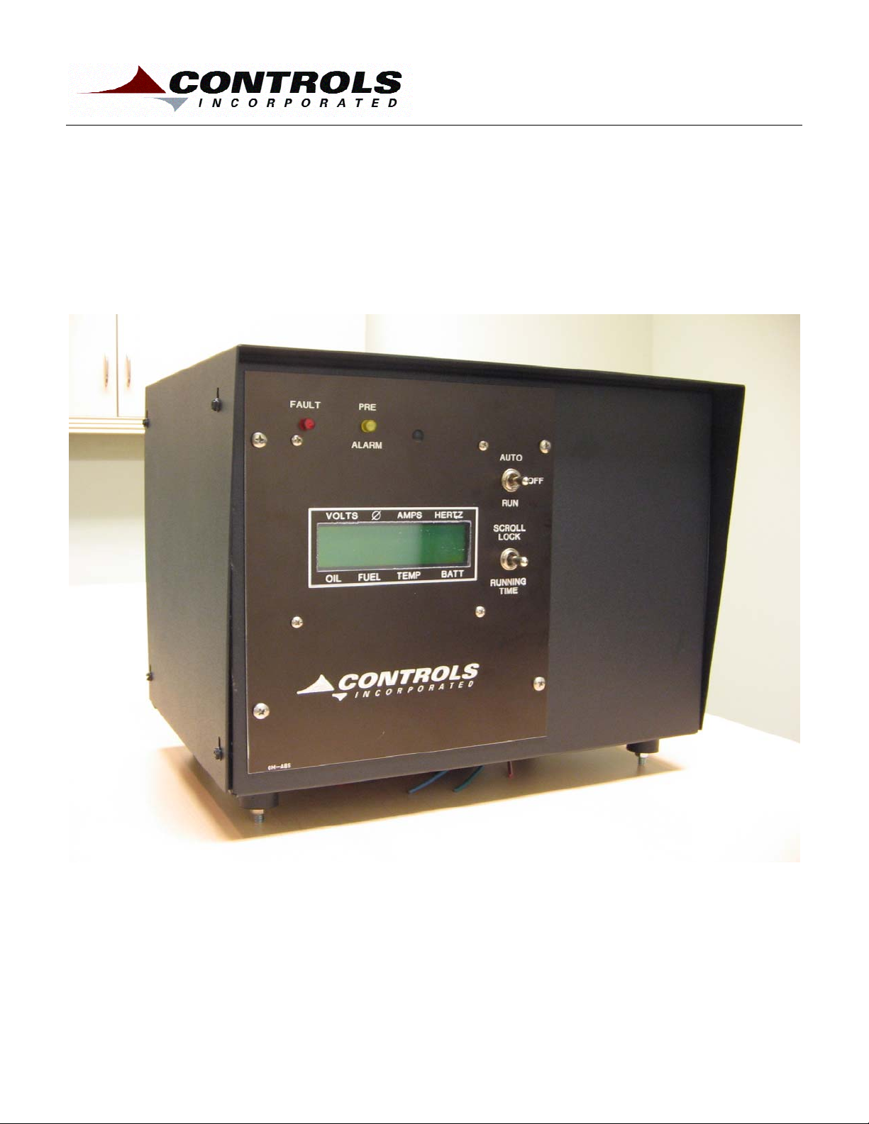
1. Introduction
The GM100 is a microprocessor-based controller for industrial engines. It is
based on the Controls, Inc. 1100-000 series controller platform.
• The product is housed in an 14”W x 10”H x 10”D
metal enclosure.
• The controller is designed to accept generic wiring
harnesses using circuit board mounted Molex
connectors.
• Color-coded engine and AC wiring harnesses are
available from Controls, Inc. for simple installations.
• The backlit digital display is 1”H x 4”W with two rows
of 16 characters. Character height is approximately
½”. Operating temperature is –20C to +70C.
Extreme temperature ranges available.
Model
• Operating voltage is 12 or 24 VDC.
• AC Voltages can range from single or three phase
systems up to 600 VAC. Controller automatically
senses.
• Current transformers can be used up to 2000:5
amps.
• Engine pre alarm and alarm parameters are
monitored with corresponding amber or red LED
illuminations above the digital display.
• Optional Remote Annunciation or Remote Relay
modules available for expansion.
PART NUMBER BREAKDOWN
GM100 14 252 K
Enclosure
14X10X10
CT Size (250:5)
And Qty (2)
“Kit” Includes
Harness
Press / Temp Senders
(2) Diodes, Fuse
2
Page 4
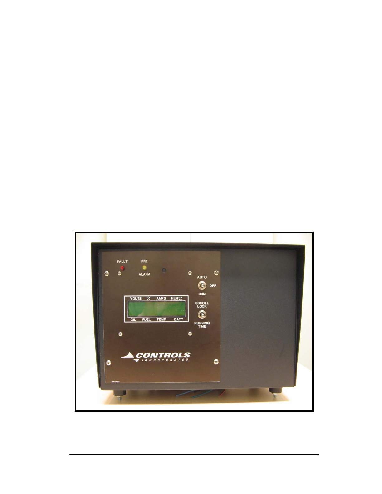
2. Interface
• LCD Display – The backlit digital display is 1”H x
4”W with two rows of 16 characters. Character
height is approximately ½”.
• Eight full-time display parameter are:
· Water Temp (Degrees F) · Batter Volts
· Oil Pressure (PSI) · Fuel Level
· AC Current · AC Voltage
· Frequency (Hertz) · Phase
• Panel Operation Toggle Switch – Auto / Off / Run
• Running Time / Scroll Lock Toggle Switch
• Amber (Pre Alarm) LED and Red (Alarm) LED
located above the digital display.
3
Page 5
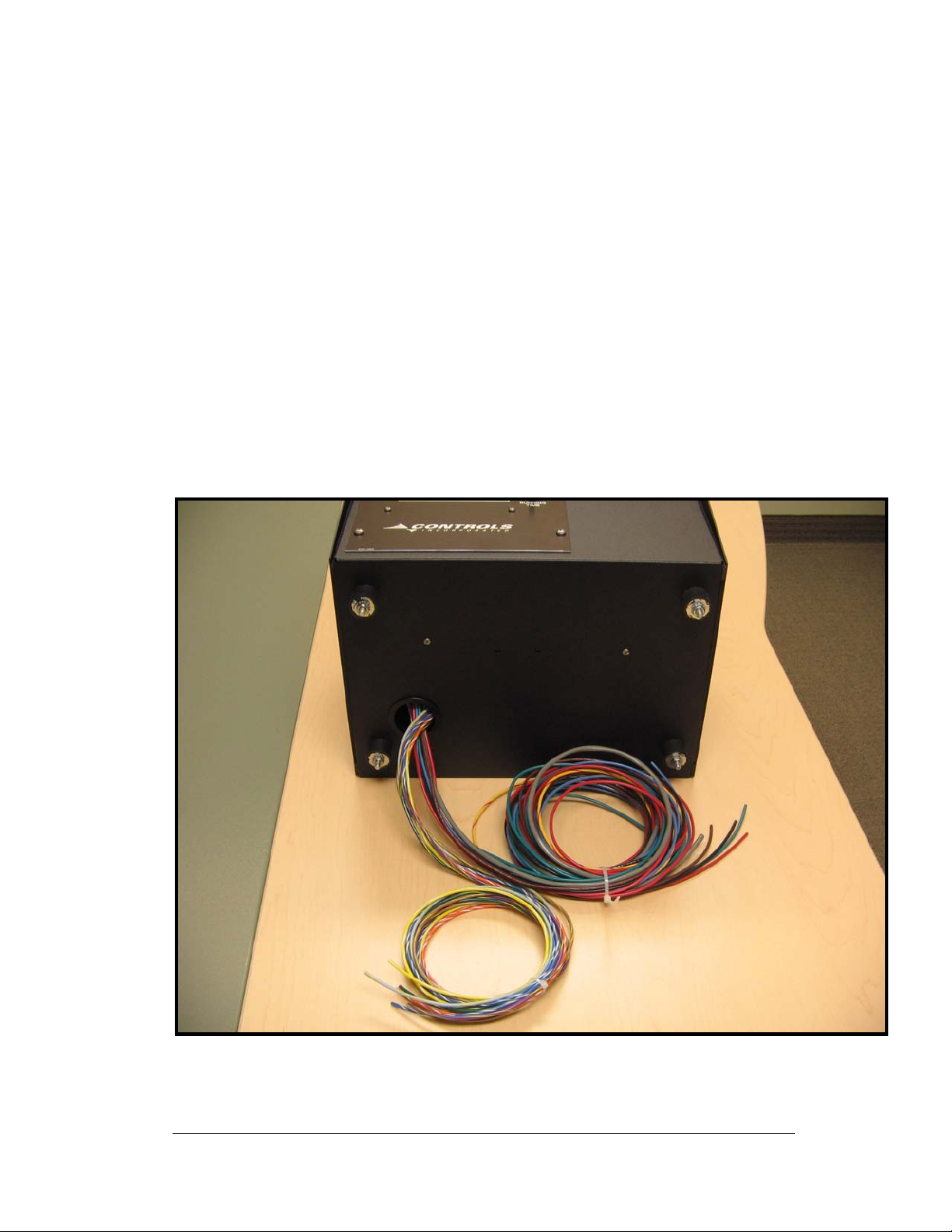
3. Enclosure
• The product is housed in an 14”W x 10”H x 10”D
metal enclosure and supplied with four vibration
isolators to mount the unit to a horizontal surface.
• Removing the eight sheet metal screws holding the
wrapping lid in place can access the inside of the
enclosure.
• Wiring harness exits out a guarded hole in the
bottom of the enclosure.
Wire Harness Exit
AC Harness
GM-H-5-AC
(Sold Separately)
Vibration Isolators
X 4
Engine Harness
GM100-H-10-E
(Sold Separately)
4
Page 6

4. Engine Start & Stop
4.1 The controller is manual and auto start capable.
4.1.1 Manual Operation
4.1.1.1 Turn the panel selector switch to RUN.
4.1.1.2 A message of “Starting Engine” will appear on the display.
4.1.1.3 The controller will engage the starter and fuel systems.
4.1.1.4 The controller automatically crank disconnects when the unit
detects 450 RPM from the engine’s speed sensor or 100+
VAC from the generator output.
4.1.1.5 To stop the engine, move the toggle switch back to the OFF
position.
4.1.1.6 Once the engine has started the controller will begin
monitoring and displaying the engine and generator
parameters.
4.1.1.7 If a fault occurs while the engine is running, the control panel
will open the run circuit to the engine’s fuel system.
4.1.1.8 To clear a fault, the panel selector switch must be cycled to the
OFF position.
4.1.2 Automatic Operation
4.1.2.1 Set the panel selector switch to AUTO.
4.1.2.2 A message of “Unit in Auto” will appear on the display.
4.1.2.3 Closing the remote start circuit to ground will initiate an engine
start sequence.
4.1.2.4 The controller has a cycle crank routine programmed for 5
crank attempts of 10 seconds each.
4.1.2.5 Opening the circuit will initiate an engine shutdown.
4.1.2.6 Note: Ground must be common to the engine battery negative
for reliable remote start signals.
5
Page 7

5. Engine Speed (Frequency) Calibration
5.1 Panel must be calibrated to engine flywheel for proper
frequency display.
5.2 Controller default is 180 pulses per revolution (180 fly wheel
teeth)
5.3 Start engine by placing the toggle switch in the RUN
position.
5.4 Move the Running Time toggle to the Scroll Lock position.
5.5 Adjust engine speed to 1800 RPM. Verify with a hand held
tachometer.
5.6 Locate the hole in the front panel above the LCD. Using
the wooden dowel supplied, press the pcb mounted button
behind the faceplate for 1 second and release.
5.7 Upon release, the Hertz will display 60.0. The control is
now calibrated to the engine flywheel.
6
Page 8

6. Engine Pre Alarms & Alarms
The controller monitors engine oil pressure, engine temperature and engine
speed directly using sensors. If measured parameters become out of
tolerance, the controller will begin to prealarm the specific condition. If the
parameter exceeds the fault values, the controller will open the run signal
causing the engine to shutdown.
6.1 Engine Pre Alarms
6.1.1 In the case of an engine pre alarm, the yellow LED will illuminate.
6.1.2 The engine will continue to run.
6.1.3 If the out of tolerance value is one of the full time display items, the
number will flash every second on the display. (Defaults shown
below)
• Low Fuel Level < 20%
7
Page 9

6.2 Engine Faults
6.2.1 In the case of an engine alarm, the red LED will illuminate.
6.2.2 The controller will open the run circuit causing the engine to stop.
6.2.3 A fault message will be displayed indicating which parameter
caused the controller to stop the engine. (Defaults shown below)
• Low Oil Pressure > 15 PSI for 5 Seconds
• High Engine Temp < 225 F for 5 Seconds
• Low Fuel Level < 1% for 5 Seconds
• Over Speed < 67.0 for 1 Second
• Over Crank
6.2.4 The control panel will keep this message displayed unit a manual
reset done by placing the Auto / Off / Run toggle switch back in the
OFF position.
6.2.5 A fault will also be cleared if a power cycle occurs.
8
Page 10

7. Auxiliary Input / Output Connections
7.1 Aux Inputs
7.1.1 Fuel Level
terminal strip inside the controller. Plug 1 Pin 12 (Light Blue Wire)
7.1.1.1 When a Stewart Warner sender type (240 – 33 ohm) is
connected, fuel level will be displayed in percentage on the LCD.
7.2 Aux Outputs
7.2.1 None
- An analog fuel level sender input is located on the
9
Page 11

8. Engine Sender Types
• Oil Pressure – Stewart Warner 240 – 33 ohm, 0-100
PSI (SD0006 Including with K part numbers)
• Engine Temperature – Stewart Warner 280-EA
Type, 100-255 F (TS4042 Including with K part
numbers)
• Engine Speed – Magnetic Pick Up, 3 VAC minimum
• Fuel Level – Stewart Warner 240 – 33 ohm, 0-100%
TS4042
½” NPT
Temp Sensor
11410-097
5/8”
MPU
SD0006
1/8”
Press Sensor
10
Page 12

9. Generator Sensing
• AC Voltage – Directly from generator output, Up to
600 VAC
• AC Current – Current transformers, 5 Amp output
(XXX: 5). Two required for single phase operation.
Three required for three phase operation. (CTs
Including with K part numbers)
Current
Transformers
11
Page 13

oard
10. Control AC / DC Adjustments
AC Volts
Adjust
AC Circuit
B
CT Input
AC Amps
Adjust
AC Voltage
485 Port
Battery
Adjust
Input
10.1 AC Voltage Adjustment – Using the pcb mounted calibration pots, the
displayed voltage can be adjusted to match
the output of the generator.
10.2 AC Amps Adjustment
– Using the pcb mounted calibration pots, the
displayed current can be adjusted to match the
output of the generator. The adjustment is
limited to the pre-programmed range of the
current transformer inputs. The size of CT’s to
be used must be known at the time of ordering.
12
Page 14

11. Product Warranty
CONTROLS, INC. is herein called “Seller”. The person, firm or corporation to whom
or which the sale is made is herein called “Buyer”. Seller warrants to the Buyer that
all products furnished under this order will conform to Seller’s specification, drawings
as described in its current catalog or quotation and will be free from defects in
materials and workmanship. Seller must approve other special requirements asked
for by the Buyer in its purchase order in writing. Parts replaced or repaired in the
warranty period shall carry the unexpired portion of the original warranty. The
foregoing is subject to the provisions that in no case will the total warranty period
extend beyond twelve (12) months from date seller ships equipment from point of
sale.
The Liability of Seller thereunder is limited to replacing or repairing at Seller’s factory
any part or parts which have been returned to the Seller and which are proved by
buyer as defective or not conforming to Seller’s specifications, drawings or other
written descriptions, accepted by Seller, provided that such part or parts are returned
by the buyer within thirty (30) days after such defect is discovered. All items
returned to Seller for repair or replacement must be sent freight prepaid to its factory.
Buyer must obtain Seller’s Return Goods Authorization prior to returning items. The
above conditions must be met if warranty is valid. Seller will not be liable for any
damage done by unauthorized repair work, unauthorized misapplication in nonsuitable environment.
In no event shall the Seller be liable for loss, damage, or expense directly or
indirectly arising from the use of the units, or from any other cause, except as
expressly stated in the warranty. Seller makes no warranties, express or implied,
including any warranty as to merchantability of fitness for a particular purpose or use.
Seller is not liable for and buyer waives any right or action it has or may have against
seller for any consequential or special damages arising out of any breach of
warranty, and for any damages buyer may claim for damage to any property or injury
or death to any person arising out of its purchase or the use, operation or
maintenance of the product. Seller will not be liable for any labor subcontracted or
performed by buyer for preparation of warranted item for return to Seller’s factory or
for preparation work for field repair or replacement. The Seller will not consider
invoicing of Seller for labor either performed or subcontracted by buyer as a liability.
This warranty shall be exclusive of any and all other warranties express or implied
and may be modified only by a writing signed by an officer of the Seller. With
respect to accessories supplied by Seller, but manufactured by others, there is no
warranty of any kind, express or implied, and specifically there is no warranty of
merchantability or fitness, except as may be set forth in any warranty the
manufactures have made to Seller and which can be passed to the Buyer.
13
 Loading...