

Page 1
5570 Comfort Care, Premier Recliner
p
5580 Cozy Comfort, Premier Recliner
NO TOOLS REQUIRED FOR ASSEMBLY!
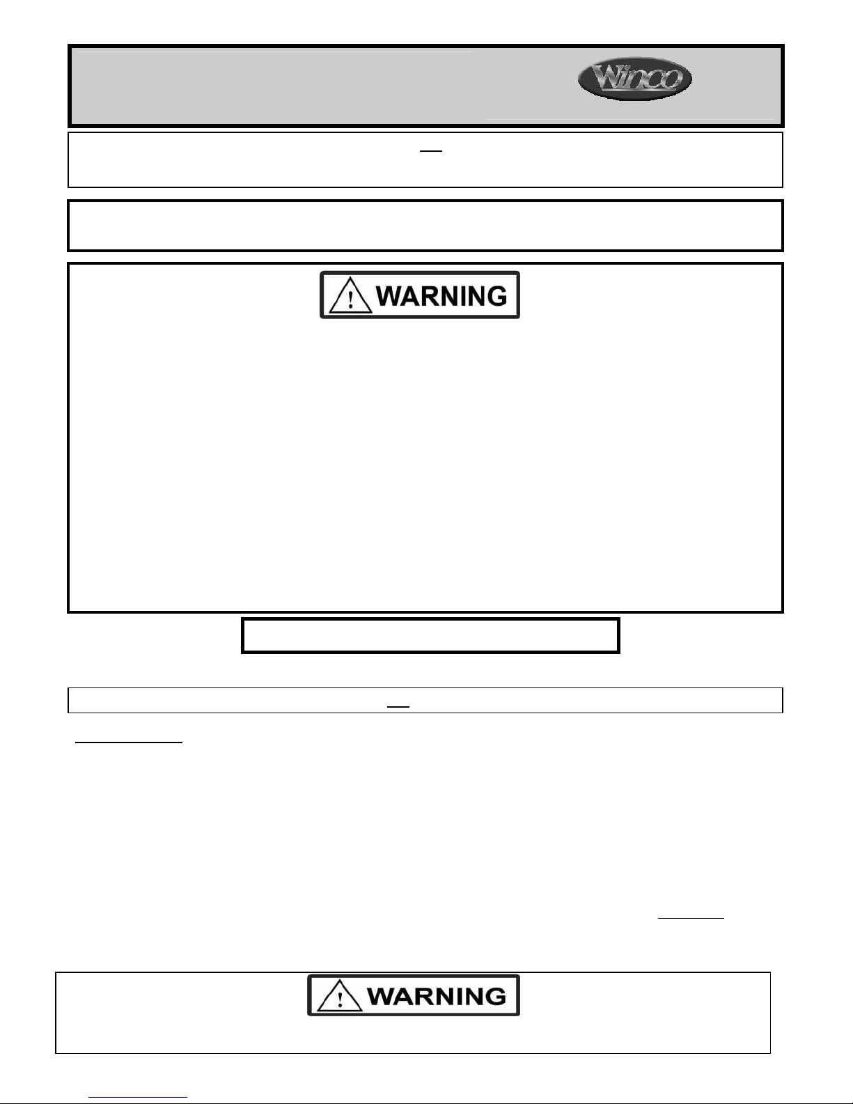
Failure to correctly install clevis pins connecting Back Frame fork holes and Seat Frame Rail ho les, will cause back
to o
006325 Revision A Date 01-28-11 JWC
PLEASE READ AND FAMILIARIZE YOURSELF WITH ALL INSTRUCTIONS BEFORE USING THIS PRODUCT.
If you have trouble understanding these instructions contact your dealer or Winco customer support, (800) 237-3377
before attempting to use this product; otherwise injury may occur.
Winco assumes no responsibility for damage or injury caused by the improper assembly, installation
or use of these products; or during assembly or maintenance of these products.
1. READ AND FOLLOW ALL DIRECTIONS.
2. NEVER use side tables as a seat.
3. DO NOT put hands, feet or clothing into any openings when changing positions on recliner. Attendant MUST
confirm that users hands and feet are safe while changing recliner positions or INJURY MAY RESULT .
4. Stay clear of the recline mechanisms.
5. Periodically, recheck tightness of all nuts, bolts and screws.
6. NEVER use the side-tables or chair arms or backrest or legrest as a seat; SERIOUS INJURY MAY OCCUR.
7. Chair MUST be in full upright position with casters locked when a patient enters or exits chair.
8. 5570 ONLY - NEVER allow a patient to exit a reclined chair with position-lock engaged or SERIOUS INJURY MAY
RESULT.
9. Lock casters at all times, except when transporting chair.
10. Chair must ALWAYS be positioned on a level surface.
11. DO NOT use recliner for Transporting in or with ANY type of vehicle or trailer. Winco recliners have not been
tested or approved for use by an occupant in any type of vehicle or trailer.
12. Immediately remove from service; Any recliner with broken recline mechanisms, torn upholstery, or other
mechanical or visible damage.
13. USE ONLY WINCO AUTHORIZED REPLACEMENT PARTS.
14. NEVER EXCEED the recommended weight capacity of 275 lbs. (124.7 kg).
15. SAVE THESE INSTRUCTIONS for future reference and training.
5570-5580 Weight Capacity = 275 lbs. (124.7 kg)
PLEASE READ AND FAMILIARIZE YOURSELF WITH ALL INSTRUCTIONS BEFORE PROCEEDING WITH ASSEMBLY
Install the Back:
1. After checking your product for any shipping damage, chair needs to be positioned upright on level surface.
Remove all packing material and hardware that was secured for shipping. Remove tape and plastic. If using
scissors or knife, please be careful not to damage upholstery.
2. Make sure footrest is in closed position & LOCK ALL CASTERS before installing chair back.
3. Remove the (2) Bow Tie Cotter Pins and the (2) Clevis Pins from the lower Back Frame Forks. DO NOT
LOOSE THESE PARTS, YOU WILL NEED THEM AGAIN!
4. Using a second person to help; Position the Back Frame Forks over the Seat Frame and align holes
HINT: If you do not have a helper; Rest the bottom of the Upholstered Back on the rear portion of the Upholstered
Seat and push the Back Assembly slightly forward to help steady the chair back.
erate poorly and may cause injury to the user or damage the chair and void warranty.
Page 1 of 4
CUSTOMER INSTRUCTIONS
.
Page 2
Page 2 of 4
FIG.1
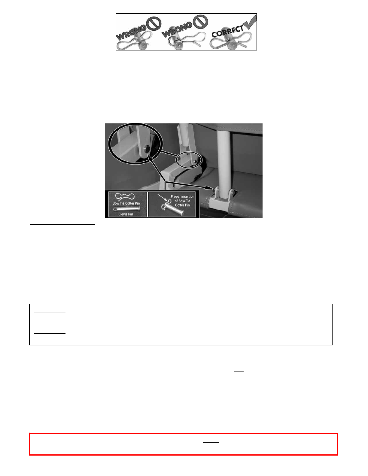
5. Use (1) one of the Clevis Pins and insert it THROUGH the inside of Back Frame Fork
, THROUGH hole in
Seat Rail Tube and; THROUGH outside of Back Frame Fork.
REPEAT FOR OPPOSITE SIDE OF CHAIR. (FIG.2)
6. Insert (2) Bow Tie Cotter Pins, into the small holes on ends of the (2) Clevis Pins you just installed. (FIG.1)
7. Remove the Bow Tie Cotter Pin and the Clevis Pin from the Back Support Strut (attached to backframe).
8. Align the holes of the Back Support Strut with the holes in the Angle Brackets (on chair frame) and insert
the Clevis Pin into these aligned holes and secure with the Bow Tie Cotter Pin.
FIG.2
Operation of the Chair:
1. NON-RESTRAINT (5570 only): To make the chair permanently non-restraint, unbolt the Position Lock Bar
from the back of the chair.
2. The 5570 & 5580 recliners have three (3) positions; UPRIGHT, SEMI-RECLINE, and RECLINE, which can be
achieved by user or attendant. 5570 Only: The position lock bar can only be engaged or disengaged by
attendant. Not all notches on Position Lock Bar are used for this model chair.
3. POSITION LOCK (5570 only): Attendant may hold the chair in a reclined position by engaging the Position
Lock. To safely accomplish this, recline the chair to the 2
with your hand until the notches on the Position Lock bars engage with the Position Lock Pins.
To release Position Lock, raise the Position Lock off of the Pins and return chair to upright position.
WARNING: Attendant must release Position Lock before patient can exit chair – If patient attempts to
exit chair with Position Lock engaged, SERIOUS INJURY MAY RESULT.
WARNING:
chair and void the warranty.
Failure to release the Position Lock before changing positions will result in damage to the
4. This chair is equipped with (3) Total Lock casters & (1) Directional Lock Caster.
Total-Lock Caster: Engaging the light grey brake tab will lock the wheel and
caster for added safety and security.
Directional-Lock Caster: Engaging the dark grey brake tab will ONLY lock the swivel mechanism, still
allowing the wheel to roll for additional steering control.
To ensure proper operation of the reclining mechanism, lubricate all pivot points with a silicone type lubricant (or lubricant
approved by your facility) at least twice yearly. Periodically recheck tightness of all screws and bolts.
Wrinkles in Vinyl – Storage and shipping can cause wrinkles of the vinyl on your Winco chair. This is normal. Please allo w 1- 2
weeks at room temperature (approx. 70 degrees) to allow for vinyl to expand back to original appearance
Periodically recheck tightness of all screws and bolts, and never use the chair arms, backrest, legrest or
006325 Revision A Date 01-28-11 JWC
tray as a seat.
nd
or 3rd recline position and lower the position lock
the swivel mechanism of the
Page 3

Operating Instructions for Table OPTIONS available for your recliner:
*Side-Table (LT, RT, DT)
To position side-tables
1. To raise table, grasp center of table and gently raise into place.
Table will automatically lock into place when released.
2. To lower table, grasp table at the center, raise and pivot down in
one movement.
“Lap Position”
1. From the sitting position, raise table up (vertical).
2. Lower table over lap
“Away” Position
1. With the table in the “lap” position, push table away
from user.
“Side-Storage” Position
1. To return table to the side-storage position, pull table into
“lap” position.
2. Push table up into vertical position then slowly lower table into
its side-storage position. (FIG.4 NOTE)
“Lap Position”
1. To place pivot-table in “lap” position, pivot the table away
from chair and pull over lap. (FIG.5)
2. Tighten star-knob to secure the pivot-table in the lap position
“Exit” Position
1. With the table in the “lap” position, loosen star-knob & push
table away to exit chair.
Remove Pivot-Table
1. Loosen pivot-table star knob
2. Pull up on pivot-table until the table stem comes out of the
black bracket.
006325 Revision A Date 01-28-11 JWC
(FIG.4)
IV Pole
*Versa-Table (VS, VN, VP)
(For chair entry & exit)
*Pivot Table (NP, PN)
Contoured Headrest
IV
(FIG.3)
FIG.3
FIG.4
Other available Options:
Torso Support
CH00
TS00
Page 3 of 4
DO NOT DROP TABLE INTO
ANY POSITION
FIG.5
Side Cushion
SC00
Page 4

Page 4 of 4
Visit our website www.wincomfg.com/product-documents/parts-lists for a complete part s list catalog of your chair or
call Customer Service @ 1-800-237-3377 to request it by mail.
006325 Revision A Date 01-28-11 JWC
 Loading...