

Winco 50PTOC4-03/1, 50PTOC4-04/1, 50PTOT4-03/1, 50PTOT4-17/1, 50PTOC4-18/1 Installation And Operator's Manual
...Page 1
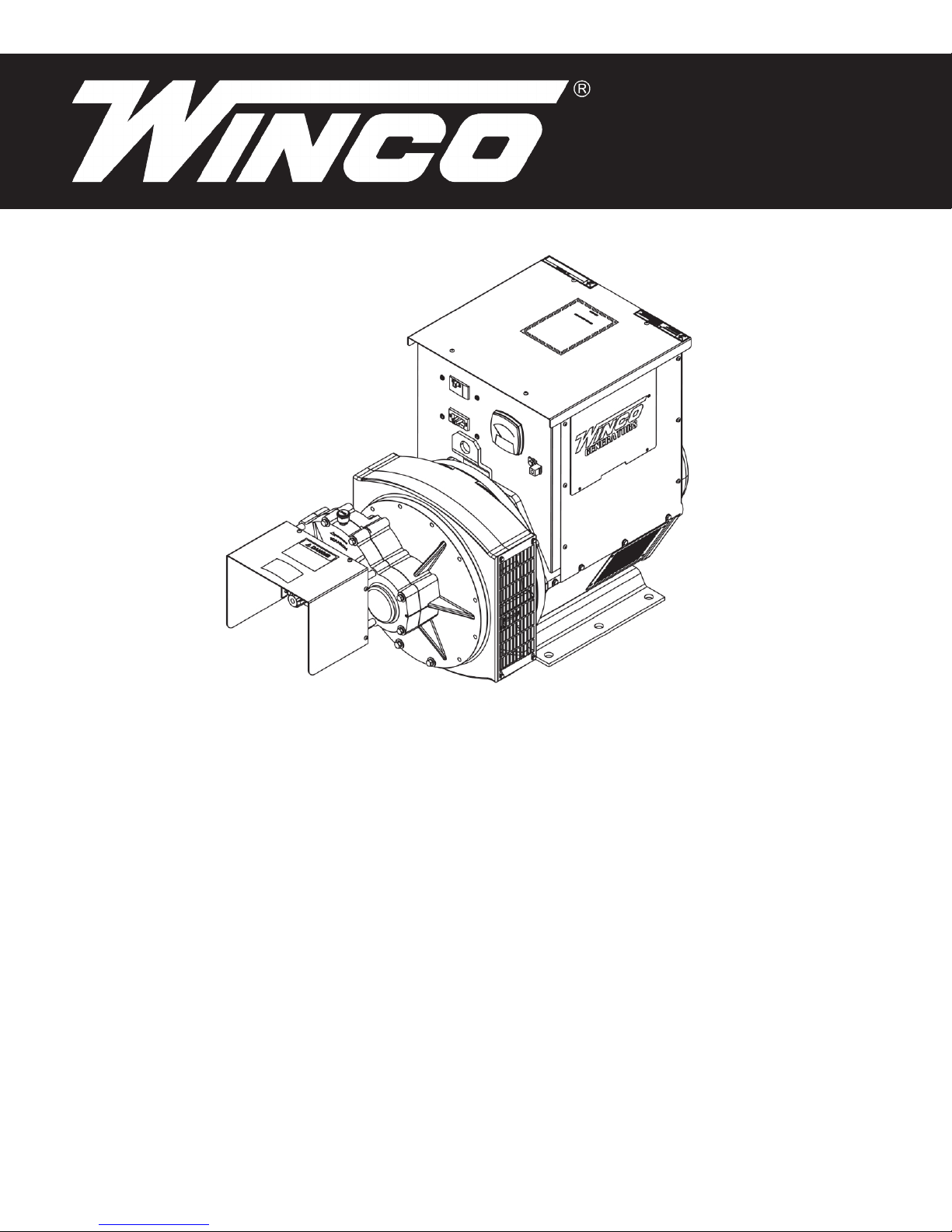
50kW-55kW
PTO GENERATORS
INSTALLATION AND
OPERATORS
WINCO INC. 225 S. CORDOVA AVE. LE CENTER, MN 56057 507-357-6821
MANUAL
SERVICE DEPT. 507-357-6831
www.wincogen.com
Page 2

TABLE OF CONTENTS
SAVE THESE INSTRUCTIONS 2
TESTING POLICY 2
SPECIFICATIONS 3
50PTOC4-03/1
50PTOT4-03/1
50PTOC4-04/1
50PTOT4-04/1
50PTOC4-17/1
50PTOT4-17/1
50PTOC4-18/1
50PTOT4-18/1
SAFETY 4
IMPORTANT SAFETY INSTRUCTIONS
CALIFORNIA PROPOSITION 65
ANSI SAFETY DEFINITIONS
PREPARING THE UNIT 5
UNPACKING
SAVE THESE INSTRUCTIONS
This manual contains important instructions that should be followed
during installation and maintenance of the generator. Read and
understand all instructions in the manual before starting and operating
the generator.
USING THIS MANUAL
Congratulations on your choice of a WINCO generator. You have
selected a high-quality, precision-engineered generator designed and
tested to give you years of satisfactory service.
To get the best performance from your new generator, it is important
that you carefully read and follow the operating instructions in this
manual.
Should you experience a problem please follow the “Troubleshooting
Tables” near the end of this manual. The warranty listed in the manual
describes what you can expect from WINCO should you need service
assistance in the future.
INTRODUCTION 5
INSTALLATION 5
FOUNDATION MOUNTING
TRAILER MOUNTING
ELECTRICAL CONNECTIONS 6
GROUNDING
THREE-POINT HITCH KIT
PLUG KIT
OPERATION 9
PRE-START CHECKS 9
GENERATOR PROCEDURES 10
START-UP
SHUTDOWN
MAINTENANCE 11
GENERAL INFORMATION
PERIODICAL MAINTENANCE
LUBRICATION
CLEANING & INSPECTION
GENERATOR STORAGE
TROUBLE SHOOTING TABLE 13
WIRING DIAGRAM 14
COPY YOUR MODEL AND SERIAL NUMBER HERE
No other WINCO generator has the same serial number as yours. If
you should ever need to contact us concerning this unit, it will help us
to respond to your needs faster.
MODEL __________________________________________________
SERIAL NUMBER _________________________________________
PURCHASE DATE _________________________________________
DEALER NAME ___________________________________________
DEALER PHONE # ________________________________________
TESTING POLICY
Before any generator is shipped from the factory, it is fully checked for
performance. The generator is loaded, and the voltage, current, and
frequency are carefully checked.
WIRING DIAGRAM 15
36 MONTH LIMITED WARRANTY 16
OPM-137
Rated output of generator is based on engineering tests of typical units,
and is subject to, and limited by, the temperature, altitude, fuel, and
other conditions specied by the manufacturer of applicable engines.
2
REV A
Page 3

SPECIFICATIONS
50PTOC4-03/1
Watts 50,000
Volts 120/240
Phase Single
Amps 208
Input Speed 540 RPM
Generator Speed 1800 RPM
AVR AS440
Input Shaft 1 3/8” 6-spline
Required Tractor PTO HP 100
Gear Lube
Volume 0.875 Pint
Type SAE 80-90W-140
50PTOT4-03/1
Watts 50,000
Volts 120/240
Phase Single
Amps 208
Input Speed 1000 RPM
Generator Speed 1800 RPM
AVR AS440
Input Shaft 1 3/8” 6-spline
Required Tractor PTO HP 100
Gear Lube
Volume 0.875 Pint
Type SAE 80-90W-140
50PTOC4-17/1
Watts 50,000
Volts 120/240
Phase Three
Amps 120
Input Speed 540 RPM
Generator Speed 1800 RPM
AVR AS440
Input Shaft 1 3/8” 6-spline
Required Tractor PTO HP 100
Gear Lube
Volume 0.875 Pint
Type SAE 80-90W-140
50PTOT4-17/1
Watts 50,000
Volts 120/240
Phase Three
Amps 120
Input Speed 1000 RPM
Generator Speed 1800 RPM
AVR AS440
Input Shaft 1 3/8” 6-spline
Required Tractor PTO HP 100
Gear Lube
Volume 0.875 Pint
Type SAE 80-90W-140
50PTOC4-04/1
Watts 50,000
Volts 120/208
Phase Three
Amps 138
Input Speed 540 RPM
Generator Speed 1800 RPM
AVR AS440
Input Shaft 1 3/8” 6-spline
Required Tractor PTO HP 100
Gear Lube
Volume 0.875 Pint
Type SAE 80-90W-140
50PTOT4-04/1
Watts 50,000
Volts 120/208
Phase Three
Amps 138
Input Speed 1000 RPM
Generator Speed 1800 RPM
AVR AS440
Input Shaft 1 3/8” 6-spline
Required Tractor PTO HP 100
Gear Lube
Volume 0.875 Pint
Type SAE 80-90W-140
50PTOC4-18/1
Watts 55,000
Volts 277/480
Phase Three
Amps 66
Input Speed 540 RPM
Generator Speed 1800 RPM
AVR AS440
Input Shaft 1 3/8” 6-spline
Required Tractor PTO HP 110
Gear Lube
Volume 0.875 Pint
Type SAE 80-90W-140
50PTOT4-18/1
Watts 55,000
Volts 277/480
Phase Three
Amps 66
Input Speed 1000 RPM
Generator Speed 1800 RPM
AVR AS440
Input Shaft 1 3/8” 6-spline
Required Tractor PTO HP 110
Gear Lube
Volume 0.875 Pint
Type SAE 80-90W-140
3REV A
OPM-137
Page 4

SAFETY
IMPORTANT SAFETY INSTRUCTIONS
SAVE THESE INSTRUCTIONS
This manual contains important information that should be understood
and followed before the installation, operation and maintenance of the
generator. Failure to follow the safety instructions in this manual could
result in serious injury or death. Keep this manual available for future
reference.
CALIFORNIA PROPOSITION 65
WARNING: This product contains crude oil, gasoline,
diesel fuel and other petroleum products, Antifreeze to
which can expose you to chemicals including toluene
and benzene, Ethylene glycol (ingested) which are
known to the State of California to cause cancer, birth defects or other
reproductive harm and developmental issues.
For more information go to www.P65Warning.ca.gov.
3. NOISE HAZARD -
Excessive noise is not only tiring, but continual exposure can lead to
loss of hearing.
A. Use hearing protection when working around this
equipment for long periods of time.
B. Keep your neighbors in mind when permanently installing this
equipment.
4. CLEANLINESS -
Keep the generator and surrounding area clean.
A. Remove all grease, ice, snow or materials that create slippery
conditions around the unit.
B. Remove any rags or other materials that could create a
potential re hazard.
C. Carefully clean up any gas or oil spills before starting the unit.
5. SERVICING EQUIPMENT -
ANSI SAFETY DEFINITIONS
DANGER:
DANGER indicates an imminently hazardous situation which, if not
avoided, will result in death or serious injury. This signal word is to be
limited to the most extreme situations.
WARNING:
WARNING indicates a potentially hazardous situation which, if not
avoided, could result in death or serious injury.
CAUTION:
CAUTION indicates a potentially hazardous situation which, if not
avoided, may result in minor or moderate injury. It may be used to alert
against unsafe practices.
NOTE: CAUTION is also used on the unit labels and in this manual to
indicate a situation that could result in serious damage or destruction of
the equipment and possible personal injury.
1. ELECTRIC SHOCK -
The output voltage present in this equipment can cause a fatal electric
shock. This equipment must be operated by a responsible person.
A. Do not allow anyone to operate the generator without proper
instruction.
B. Guard against electric shock.
C. Avoid contact with live terminals or receptacles.
D. Use extreme care if operating this unit in rain or snow.
E. Use only three-prong grounded plugs and extension cords.
F. Be sure the unit is properly grounded to an external ground rod
driven into the earth.
2. FIRE HAZARD -
A. Keep a re extinguisher nearby and know its proper use. Fire
extinguishers rated ABC by NFPA are appropriate.
OPM-137
All service, including the installation or replacement of service parts,
should be performed only by a qualied technician.
A. Use only factory approved repair parts.
B. Do not work on this equipment fatigued.
C. Use extreme caution when working on electrical components.
High output voltages from this equipment can cause serious
injury or death.
D. Installing a generator is not a “do-it-yourself” project. Consult
a qualied, licensed electrician or contractor. The installation
must comply with all national, state, and local codes.
6. INSTALLATION -
Installing a PTO generator is not a “do-it-yourself” project. Consult
a qualied, licensed electrician or contractor. The installation must
comply with all national, state, and local codes.
A. Never operate the PTO drive generator without having it
properly mounted to a concrete base or approved trailer.
b. Never connect the PTO generator to an existing electrical
system without installing an isolation transfer switch.
C. Always insure the drive shaft is straight and level before
operating the generator.
8. OPERATION - PTO drive shafts (tumbling bars) have many inherent
dangers, extreme caution must be exercised when using them.
A. NEVER allow children around the drive shaft when it is in
operation.
B. Keep all safety guards and shields in place and securely
tightened.
C. Never operate a drive shaft that has been damaged or had the
safety shield removed.
D. Never step over a drive shaft while it is running.
E. Never wear a necktie, loose articles of clothing, or anything else
that can be caught in moving parts.
F. Never try to stop drive shaft with your hand or your foot.
4
REV A
Page 5
PREPARING THE UNIT
INSTALLATION
UNPACKING
CAUTION: EQUIPMENT DAMAGE
When you unpack your new generator, be sure to remove all of the
information sheets and manual from the carton.
1. As you receive your unit, it is critical to check it for any damage. If
any damage is noted, it is always easiest to refuse the shipment and
let WINCO take care of the freight claim. If you sign for the unit, the
transfer of the ownership requires that you le the freight claim
2. Before proceeding with the preparations of your new generator
for operation, take a couple of minutes to ensure the unit you have
received is the correct model and review the specication pages in
this manual to ensure that this unit meets your job requirements.
INTRODUCTION
The WINCO power take-off generators are designed primarily for farm
use as a standby electrical power supply, utilizing the power take-off
of a tractor or truck as the prime mover. This PTO drive generator will
provide, 120/240V 1-PH, 120/208V 3-PH, 120/240V 3-PH, 277/480V
3-PH, or 346/600V (depending on model), 60Hz electrical service when
properly driven.
DO NOT operate and/or store the unit outside during inclement
weather without adequate protection from the elements. Failure to do
so will damage the unit.
NOTE:
It is acceptable to use this generator with a tractor with less HP
output than required for full power operation. The generator will work
but produce only as much kW output as the tractor can supply HP
for. For example, a 20 HP output tractor will deliver a maximum of
approximately 10 kw.
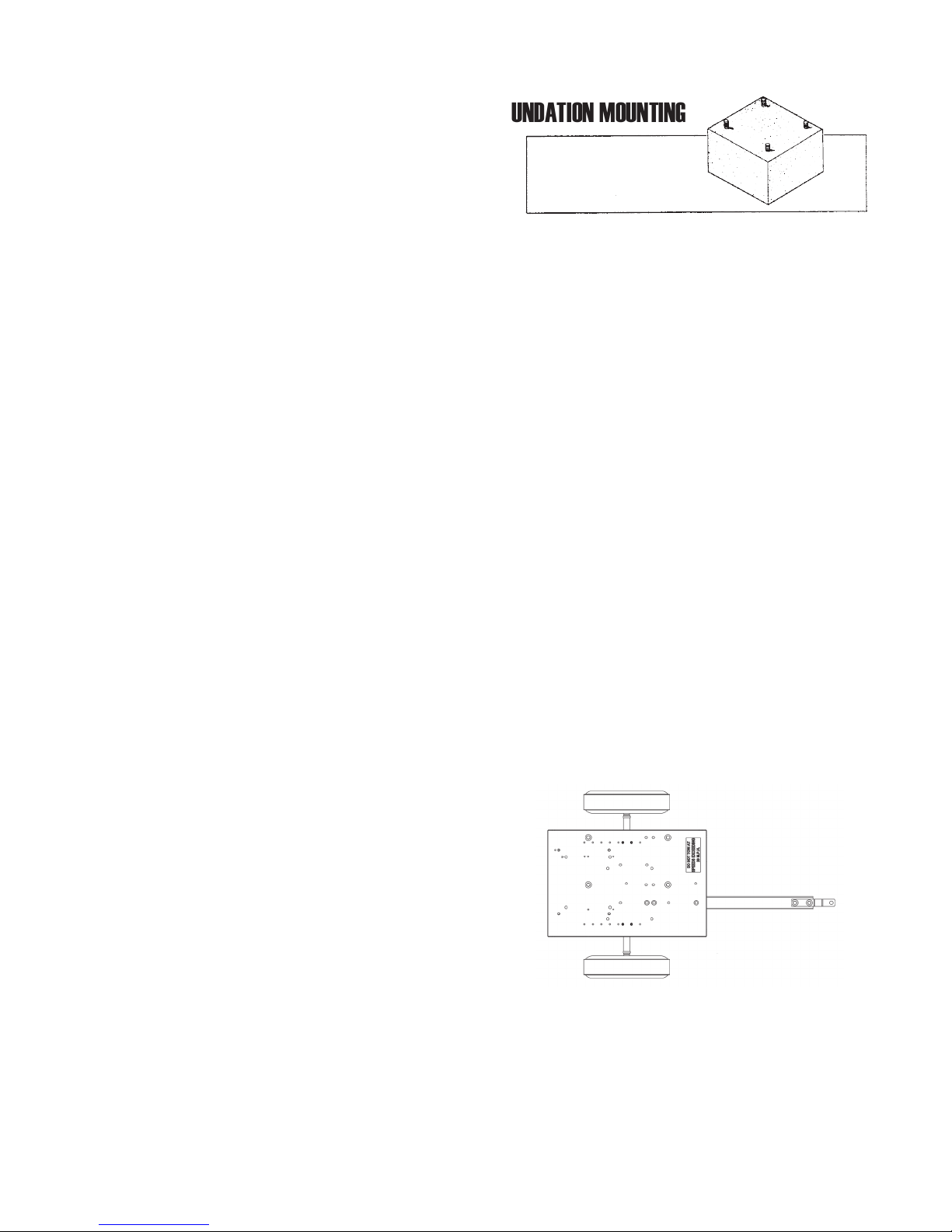
FOUNDATION MOUNTING
Mount the generator on a foundation if it is to be used as a permanent
or standby power source. When planning a foundation consider the
following points:
A. The foundation location should enable aligning the drive shaft
(tumbling bar) in a straight or nearly straight line between the power
take-off and the generator input shaft. Misalignment must be
less than 5 degrees during generator operation, even though
the mechanical design of the tumbling bar would allow greater
misalignment.
B. The foundation must be solid enough to absorb generator starting
and reected load torque during operation.
C. The foundation surface should be at.
D. Space is required around the generator for mounting switching
devices, making connections, and for servicing.
E. For dimensions needed for install for your specic generator, please
refer to it’s outline drawing. The hardware needed is dependent on
your distinct application.
F. The generator mounting bracket must rest evenly and rmly on the
foundation. Install shims if necessary to even out the foundation
under the mounting pads then bolt the generator rmly in place.
TRAILER MOUNTING
Optional
If you are using a tractor with more HP than required to run the
generator care should be taken to ensure that you do not overload the
generator causing overheating and equipment damage. Observe input
RPM specications.
The generator may be foundation mounted for use as standby power
source, or trailer mounted, and used as portable electrical power
sources for areas where commercial power is not readily available,
such as out buildings.
This generator includes a frequency meter to warn against high or
low frequency, three output power receptacles, an overload protection
circuit, and an electronic excitation circuit. To reduce maintenance
problems, the coupling between the generator input shaft and rotor
consists of precision helical gearing rather than a chain link drive. The
input shaft is a 1 3/8in. 6-spline.
IMPORTANT: THE MANUFACTURER STRONGLY RECOMMENDS
RUNNING THE GENERATOR UNDER LOAD AT
LEAST ONCE A MONTH IN ORDER TO EVAPORATE ANY
ACCUMULATED MOISTURE CONDENSATION.
Mount the generator on a trailer if you plan to use it as a portable
power source. When selecting or building a trailer to mount the
generator, consider the following points:
A. The trailer construction must be strong enough to support the
generator.
B. The design of the trailer must enable the trailer to remain stable
during operation, and to resist tipping caused by generator starting
and reected load torque.
5REV A
OPM-137
Page 6

C. The trailer height and mounting position of the generator on the
trailer should enable aligning the drive shaft (tumbling bar) in
a straight or nearly straight line between the power take-off and
generator input shafts. Misalignment must be less than 5 degrees
during generator operation, even though the mechanical design of
the tumbling bar would allow greater misalignment.
D. The generator mounting area of the trailer bed should be at.
The frame pads must rest rmly on the trailer bed. Install shims if
necessary to even out the bed under the mounting pads, then bolt the
generator rmly in place.
ELECTRICAL CONNECTIONS
GROUNDING
Proper grounding of your generator is application dependent. Carefully
evaluate your planned use of your generator to understand which
grounding you require. If you are not sure what to do, contact a
competent professional to assist you. The NFPA 70 250:34-35 are good
technical references.
STANDARD PORTABLE GENERATOR
WARNING: PERSONAL INJURY & EQUIPMENT DAMAGE
Trailer may tip over and cause injuries if wheels are not spaced far
enough apart.
THREE-POINT HITCH KIT
Optional
WARNING: PERSONAL INJURY & EQUIPMENT DAMAGE
When using the 3-point hitch assembly all three points must be
attached to the tractor. Failure to do so will cause the generator to tip
when lifting it, damaging both the t-bar and the generator.
A. The three point hitch must be attached to the tractor at all times
during operation.
B. When operating the generator the three point hitch and generator
must be sitting on at level ground. All four deck pads must be
in constant contact with the ground at all times. This will reduce the
vibration in both the generator and the tumbling bar.
C. For safety the generator must be bolted to the three point hitch deck
using all four mounting bolts.
Your WINCO portable generator ships with a bonded neutral. You can
safely use this generator without external grounding as long as all
loads are powered through the receptacle panel.
VEHICLE-MOUNTED GENERATOR
Your WINCO portable generator ships with a bonded neutral. When
mounted to a vehicle to safely distribute power it is necessary that
the generator frame is bonded to the vehicle frame. The generator
should only supply equipment that is cord and plug connected through
receptacles mounted on the generator or the vehicle.
PERMANENTLY INSTALLED GENERATORS
This WINCO portable generator ships with a bonded neutral and
overcurrent protection. NFPA 70 refers to this as a “separately derived
system.” When connecting it to a building a transfer switch specically
designed for GFCI and bonded neutral generators is required.
CAUTION:
Only qualied electricians should install electrical wiring. Wiring must
conform to all applicable national, state, and local codes. (Reference:
National Fire Protection Association Manual No. 70, National Electrical
Code.)
OPM-137
DANGER: PERSONAL INJURY:
A manual transfer switch must be installed to separate the generator
and the commercial power lines. The switch must isolate the generator
from the commercial power lines and the load when the generator is
on standby, and must isolate the commercial power lines from the load
and the generator when the generator is supplying power. See the
following diagrams.
A properly rated and installed double throw manual power isolation
transfer switch must be used with a standby generator. The transfer
switch isolates the load from the power line and allows you to safely
operate your loads without endangering the power line repair crew. See
diagram on page 8.
The load, connected to the normal terminals of the transfer switch, is
energized by the normal power line when the switch is in the normal
position. The generator, connected to the emergency terminals of the
switch, furnishes power when the switch is in the emergency mode
position.
6
REV A
Page 7

There are two ways to install a manual transfer switch. The rst
shown on the left side of the diagram on page 8, is to install the switch
between the watt-hour meter and the normal distribution panel. As
with any system you must install an entrance rated breaker before the
manual transfer switch. The manual transfer switch must in all cases be
equal to or greater than the rating of the entrance rated breaker.
The second way to install the system is to purchase and install an
emergency distribution panel and move the circuits you wish to back
up to the new distribution panel. In this case the manual transfer switch
only has to be sized to the amperage of the circuit breaker in the main
distribution panel that is feeding it. See the right hand drawing of the
diagram on page 8.
WINCO recommends a 1 GA wire size for these units. If a smaller
gauge is desired, you will need to use bushings for the three-phase
units. Bushings do come standard with the 480V Anderson Connection
plug kit.
If you require different inserts or contacts for local code, WINCO has a
variety of different inserts and contacts available. Contact the factory at
507-357-6831 for pricing.
WARNING: EQUIPMENT DAMAGE
Never use acid core solder. When soldering insure no excess solder
runs down on the contact surface - Solder on the contact surface will
not allow the contacts to mate properly causing them to burn up.
Before deciding which system to install, rst determine which loads you
can safely run on your PTO generator and the cost of buying a large
manual transfer switch versus the cost of a smaller switch and the
additional distribution panel.
PLUG KIT
The bag contains an instruction sheet, 2 plug bodies, four or six
contacts, two handle and the hardware to assembly the disconnect
plug. You will need to purchase the appropriate length of ne stranded
copper wire for your application in order to complete the assembly of
the disconnect plug.
Single Phase
120/240V
Each wire should be stripped back 7/8 of an inch and inserted into
one of the contacts in the plug kit. You will then either need to solder
them together using a good grade of resin core solder or they can be
crimped with an appropriate compression crimper or both.
Approved Crimping tools are:
1. Anderson Power Products
2. ETC Model HHS hydraulic crimper
3. ITT Blackburn NO. 1640
4. T&B (Thomas & Betts) #TBM5
To complete the assembly of the disconnect plug refer to the instruction
sheet in the plug kit.
WARNING: ELECTRICAL SHOCK
DURING THE NEXT STEP, THE LOAD DISCONNECT PLUG
SHOULD NOT BE PLUGGED INTO ITS RECEPTACLE. ALSO, MAKE
SURE THAT THE EQUIPMENT TO WHICH THE PLUG LEADS
(CABLES) ARE BEING CONNECTED IS NOT ENERGIZED (LIVE).
Strip the insulation off the free end of each of the plug leads (cables),
and connect them to the load transfer switch (or directly to the load).
Three Phase
120/208V & 120/240V
Three Phase
277/480V
7REV A
OPM-137
Page 8

Typical Connection Methods for Generator Power Service
Emergency
Distribution
IMPORTANT: When making standby service hook up, make sure load to be
transferred to standby generator will not exceed generator rating.
Emergency
Power
System
Standby
Generator
TYPICAL HOOK UP FOR
SUPPLYING ALL CIRCUITS
SUPPLYING ONLY ESSENTIAL CIRCUITS
WITH EMERGENCY POWER
To Power Line Master Switch To Power Line Master Switch
Watthour
Meter
L1
G3
G1
L3
Transfer
Switch
To
Range
To
Water
Heater
TYPICAL HOOK UP FOR
WITH EMERGENCY POWER
Watthour
Meter
Main
Distribution
Panel
To Air
Conditioner
To
Range
To
Water
Heater
To Lights
To Lights
To Lights
T1
T3
Distribution
Panel
To Air
Conditioner
To Refrig.
To Appliances
To Furnace
Standby
Generator
To
Lights
To
Lights
To
Lights
G3
G1
T1
L1
L3
Transfer
Switch
T3
Emergency
Power
System
To
Refrig.
To
Appliances
To
Furnace
Panel
OPM-137
8
REV A
Page 9

0
"
1
7. Check all electrical connections in the system to be ener-
gized by the generator. Make sure the connections are cor-
rect and are tight.
8. Make sure all loads are turned off. Do not start the genera-
tor under load.
GENERATOR STARTING PROCEDURE
1. With the power take-off drive disengaged, start the engine
which will drive the generator. Run the engine long enough
to warm it up before proceeding, so that it will run smoothly
and achieve full power under generator load.
2. With engine idling, engage the power take-off drive.
3. Watch the voltmeter on the generator and slowly increase
engine speed until the output reaches approximately 260
volts, in green portion of voltmeter scale.
4. With engine and generator running smoothly, switch on
the electrical load while watching the voltmeter.
NOTE: Equipment Damage
If the load includes motors turn them on one at a time, highest
starting current motor first, next highest second, etc.
Readjust engine throttle to keep generator output under load
at 240V (in green portion of voltmeter scale). If engine is
equipped with speed governor, it may automatically readjust
the throttle as the load changes and keep the generator output
at the proper level. However, some governors are not sensitive
enough to maintain proper output under changing load, and in
such cases the throttle will have to be manually readjusted .
OPERATION
PRE-START CHECKS
OUTPUT POWER AVAILABLE AND LOAD DETERMINATION
Before using the generator, read and understand the following
information.
Generator output current (amperage) is internally limited by three circuit
breakers. If too much demand is placed on a generator output (if you
try to drive too many motors with it, for example), one of the circuit
breakers will trip, cutting off the output in order to protect the generator.
A 20 Amp push-to-reset circuit breaker protects the 120V duplex
receptacle output circuit. 20 Amps is the total limit for both outputs
of the duplex receptacle. The 480V is equipped with the Anderson
receptacle only.
A 50 Amp toggle circuit breaker protects the 240V receptacle output
circuit. The 480V is equipped with the Anderson receptacle only.
A large two pole (three pole for three phase) switch type main circuit
breaker protects the generator windings and output circuits, including
the load disconnect receptacle outputs. The load disconnect receptacle
is the largest gray receptacle on the generator output panel.
To aid in determining how much load can be applied to the generator,
and how it should be distributed among the generator output
receptacles, the following formulas may be useful. Get load voltages,
current, and wattage from the nameplates on the equipment in the
load.
Load current (in Amps) x Load voltage = Load wattage
Amps x Volts = Watts
Watt/1000 = kW
WARNING: PERSONAL INJURY
When working on or around these generators, do not wear loose tting
clothing or any articles that may get caught in moving parts.
1. Visually inspect the generator. Check for:
A. Correct mounting
B. Physical damage
C. Debris in cooling vents and screens (could cause generator to
overheat)
IMPORTANT: The manufacturer recommends that, if the generator
has been stored for any length of time, before using it, the operator
removes the control box cover and cooling fan screen. Then inspect
the generator for rodent nests or other objects that could cause the
generator binding and/or overheating. See “cleaning portion of the
Maintenance section.
2. Check gearcase oil level by removing the plug located on the
backside of the gearcase marked “OIL LEVEL”. To rell oil, see
LUBRICATION in the MAINTENANCE section in this manual.
NOTE: Either too little or too much oil can harm the equipment.
Oil Level Plug
Load wattage / Load voltage = Load current (in Amps)
Example: 250W, 120V oodlight load: 250W / 120V = 2 Amps
NOTE:
Electric motors require more current to start than to run. Commonly,
the current rating given on a motor nameplate is the full load (running)
current required by the motor, not its starting current, which is a lot
higher. Motor starting current requirements vary greatly, by motor size
and type. Repulsion-induction type motors are the easiest to start,
typically using 1 1/2 to 2 1/2 times as much current to start as to run.
Capacitor type motors usually require 2 to 4 times as much current
to start as to run. Split-phase type motors are the hardest to start,
normally using 5 to 7 times as much current to start as to run.
3. Make sure the drive shaft (tumbling bar) is assembled with its
universal joint knuckles “synchronized”. If the knuckles are not
synchronized, the bar will chatter when rotating, which will cause the
generator output voltage to icker.
9REV A
OPM-137
Page 10

DANGER: PERSONAL INJURY
Power take-off must be DISENGAGED at this time.
GENERATOR PROCEDURES
4. Couple the tractor to the generator with the drive shaft (tumbling
bar). Couple the tumbling bar to the generator input shaft rst, then
to the power take-off shaft. Check alignment, tractor, power take off shaft (tumbling bar), and the generator input shaft should form a
straight (or nearly straight) line, with less than 5 degrees
misalignment between the shafts Misalignment will cause generator
output voltage to icker.
CAUTION:
Make sure that all tumbling bar lock pins are engaged and that all
safety shields are in place before operating the PTO generator.
5. Make sure no binding exists in generator or gearbox. If binding is
found, locate the cause and correct it before proceeding.
6. Make sure that the electrical loads to be driven by the generator will
not draw more current than the ratings of the generator receptacle or
cord set which will supply the current.
7. Check all electrical connections in the system to be energized by the
generator. Make sure the connections are correct and are tight.
8. Make sure all loads are turned off. Do not start generator under load.
START-UP
1. With the power take-off drive disengaged, start the engine which will
drive the generator. Run the engine long enough to warm it up
before proceeding, so that it will run smoothly and achieve full power
under generator load.
2. With the engine idling, engage the power take-off drive.
3. Watch the frequency meter on the generator and slowly increase
engine speed until frequency reaches approximately 60 Hz. The
voltage output of the generator is controlled by an Automatic Voltage
Regulator (AVR). Before turning on any load, check your voltage
output from the generator using a Volt/OHM meter. If the voltage
is either high or low, adjust the voltage level by turning the voltage
adjustment screw on the AVR. The AVR is located inside the
generator control cabinet. Once the proper voltage level is set, the
AVR should bring the voltage back to the same levl each time the
unit is started up. But, as a precaution, it should be checked each
time you use the generator. As a quick check you can plug in a
trouble light and check for normal brightness.
4. With engine and generator running smoothly, switch on the electrical
load while watching the frequency meter
NOTE: EQUIPMENT DAMAGE
If the load includes motors, turn them on one at a time, highest starting
current motor rst, next highest second, etc.
Adjust engine throttle to keep generator output under load at 60Hz.
If the engine is equipped with a governor, it may automatically adjust
the throttle as the load changes and keep the generator output at the
proper level. However, some governors are not sensitive enough to
maintain proper output under changing loads, and in such cases, the
frequency will have to be monitored closely and manually adjusted.
SHUTDOWN
1. Switch off electrical load.
2. Reduce Speed of engine driving generator to idle.
3. Disengage power take-off drive and allow generator to coast to a
stop.
WARNING: PERSONAL INJURY
Never try to manually stop the generator. Always let it coast until it
stops.
OPM-137
4. Shut off the engine.
5. Disconnect drive shaft. Power take-off end rst, then the generator
end.
10
REV A
Page 11

0
"
1
MAINTENANCE
GENERAL INFORMATION
The main components of the generator are: rotor and stator assembly,
cooling fan, brushes, brush holder assembly, end brackets. Before
performing any maintenance on the generator, isolate and/or disable
the drive system so the unit can not be accidentally started while being
repaired.
NOTE:
Do not over lubricate the universal joints.
The trouble shooting chart lists various symptoms of poor generator
operation with possible causes and the appropriate corrective action.
You will need a volt-ohm meter or test light to check some of the
causes. For some of the other causes you will need to check generator
speed. To check generator speed, you can use a frequency meter, a
tachometer, or a 120V-60Hz electric clock and a correctly operating
wrist watch (run the electric clock and a correctly power and compare
the clock’s second hand movement with that of the wrist watch. They
should run at the same speed. If the clock runs faster, generator speed
is too high, and vice versa).
CAUTION: EQUIPMENT DAMAGE
Most electrical equipment in North America operates satisfactory at
frequencies between 58.5 and 62 Hz (cycles per second). Operating
the generator at frequencies outside that range may cause damage to
the generator and/or to electrical equipment driven by the generator.
PERIODICAL MAINTENANCE
Service/maintenance items include periodic external physical
inspection for missing hardware or damage to mounting or drive
system and checking the oil level in the gearcase. It is recommended
that the generator be operated at least monthly under normal loads to
familiarize operators with the procedures and controls as well as to dry
out any accumulated condensation or other moisture in the generator
electrical windings. The maintenance and service attention invested will
ensure getting the peak performance that was designed to the unit.
Check the generator gearcase oil level before each use of the
generator. Maintain the oil level at the oil level plug height. The
generator is shipped with lubricant in the gearcase. Specications for
the gearcase lubricant are:
API Serice: GL-5
Grade: SAE 85W-90-140
Amount: 0.85 Pints
The following kind of oil are recommended for use in the generator
gearcase: Mobile SAE 85W-90-140 API Service GL-5, Sunonco/
DX XL80W90-140, Kendal Three Star 85W-140, Amoco 85W140 or
equivalent.
CAUTION: EQUIPMENT DAMAGE
Do not overll generator gearcase. Overlling causes overheating and
oil seal failure.
Change oil at least once every twelve months or 150 hours of
operation. Change it more often if you use the generator in bad
weather. Use the following procedure to change generator gearcase oil:
1. Remove gearcase breather. Soak breather in cleaning solvent, then
allow to dry.
Breather Vent
Routine preventative maintenance minimizes costly repairs and
generator down-time. Before each use, inspect the generator: gearcase
oil level should be correct, cooling vents and screens should be
clear, and generator mounting hardware should be tight. Clean and
inspect the generator after storing it for long periods, and after using
it in extremely dusty conditions or in severe weather, such as rain or
blowing snow.
LUBRICATION
The generator bearings are factory lubricated and sealed, and require
no further lubrication.
The generator input shaft should be cleaned and lubricated with a
thin lm of grease before installing the drive shaft and each time it is
removed.
The drive shaft (tumbling bar) requires greasing. Keep the universal
joints in the coupling shaft free from grease and dirt build-up.
2. Remove oil level check plug.
Oil Level Plug
3. Remove the oil drain plug, drain the oil into a clean oil resistant
container, 1 quart or larger. Check the oil for metal. Fine metal dust
11REV A
OPM-137
Page 12

in the oil does not indicate trouble, but metal chips do. Dismantle the
gearcase and look for damaged gears if you nd metal chips in the oil.
4. Replace the oil drain plug. Rell the gearcase through the breather
port with new oil of the recommended type. Fill the case until a little bit
of oil comes out of oil level check plug hole (it will take less than 1 pint
when dry).
5. Replace the oil level check plug.
6. Replace the breather.
CLEANING & INSPECTION
Use a vacuum cleaner or dry low pressure compressed air (regulated
at 25-35 PSI) to clean the generator periodically.
WARNING:
Do NOT clean the generator while it is running.
Proceed as follows:
1. Remove control box cover. Vacuum or blow dust or debris from the
control box. Inspect all wiring for correct routing, fraying insulation, and
secure connections.
2. Remove end cover. Vacuum or blow dust and debris from the inside
of the generator. Inspect wiring for loose connections, fraying insulation
and correct wire routing.
3. Replace end cover and control box cover.
GENERATOR STORAGE
Before storing the generator, apply a heavy coat of grease to the
splined input shaft. Store the generator in a sheltered area, where it is
protected against snow, rain, and excessive dust.
OPM-137
12
REV A
Page 13

TROUBLE SHOOTING TABLE
SYMPTOM POSSIBLE CAUSE CORRECTIVE ACTION
Low Output Voltage 1. Engine speed too slow.
2. Generator overloaded.
3. Inadequate engine horse power.
4. Defective or misadjusted AVR
High Output Voltage 1. Engine speed too fast.
2. Defective or misadjusted AVR
Excessive Vibration 1. Power take-off misalignment excessive.
2. Loose mounting nuts and bolts or hold-down studs.
3. Universal joints in coupling shaft worn or dry.
4. Defective bearings
No Output Voltage 1. Circuit breaker open.
2. Short circuit in the load.
3. Defective receptacles.
4. Loose (or broken) wires or connections in control
box.
5. Defective rotating rectier.
6. Defective AVR
7. Shorted or open rotor.
8. Shorted or open stator.
Output Voltage Flickering or
Fluctuating
Generator Overheating 1. Poor ventilation.
Oil Leak 1. Loose plug in gearcase.
1. Tumbling bar (shaft) misalignment
2. Engine governor may be worn or improperly
adjusted.
3. Loose connection in eld circuit
4. Tumbling bar u-joints not synchronized.
2. Generator overloaded.
3. Shorted turns in eld or armature windings.
2. Defective seal, gasket, or plug in gearcase.
1. Check engine speed. Increase RPM if necessary.
2. Reduce load if it is higher than the rated capacity of the
generator. See generator nameplate.
3. Generator requires 2.0 HP/1000 Watt output. Obtain
larger engine if necessary.
4. Adjust, repair, or replace as required
1. Check engine speed for correct input RPM.
2. Adjust, repair, or replace as required
1. Correct misalignment. It should be less than 15°.
2.Tighten mounting nuts and bolts; repair hold-down stud
mountings.
3. Repair or replace defective parts.
4. Check for possible causes. Replace defective bearings.
1. Reset circuit breakers, replace if defective.
2. Disconnect the load. Check voltage at receptacle cord set.
Check motors, appliances, and load leads for short circuit,
repair short..
3. Remove panel cover and check for voltage to the
receptacles. Replace defective receptacles..
4. Remove panel cover and check all wiring and connections.
Tighten and/or replace where necessary.
5. Test rectier. Replace if defective.
6. Repair or replace as required
7. Measure rotor resistance. Replace rotor if open or shorted.
8. Measure between leads for open or short. Replace stator if
defective.
1. Reduce tumbling bar misalignment to less than 15 degrees.
2. Set or repair defective governor.
3. Check and tighten connections.
4. Reassemble tumbling bar.
1. Clean ventilation and cooling fan screens.
2. Reduce load, then check voltage and current.
3. Replace defective components.
1. Tighten plug.
2. Replaces seal(s), gasket or plugs. Maintain correct oil level.
13REV A
OPM-137
Page 14

WIRING DIAGRAM
G1
G1
G2
G2
GND
GND
GND
GND
GND
G2
G2
G2
G2
G1
G1
G1
N
N
N
G1
G1
G1
G2
G3
G3
G2 G2
G2
G2
N
N
N
G2
GND
GND
GND
GND
GND
G1
G1
120/240V SINGLE PHASE
OPM-137
120/208V & 120/240V THREE PHASE
14
REV A
Page 15

WIRING DIAGRAM
G1
G3
G3
N
GND
GND
GND
N
N
N
N
G2
G2
G1
G1
G1
G1
G1
277/480V THREE PHASE
15REV A
OPM-137
Page 16

36 MONTH LIMITED WARRANTY
WINCO, Inc., warrants for thirty-six months from date of shipment, that it will repair or replace at its option, for the original
user, the whole or any part of the product found upon examination, by WINCO at its factory at 225 South Cordova
Avenue, Le Center, Minnesota, or by any factory-authorized service station, to be defective in material or workmanship
under normal standby use (average less than 50 hours per month) and service.
For warranty service, return the product within 36 months from the date of purchase, transportation charges prepaid, to
your nearest factory-authorized service station or the WINCO factory. THERE IS NO OTHER EXPRESS WARRANTY.
There is no other express warranty. To the extent permitted by law, any and all warranties, including those of
merchantability and tness for a particular purpose, are limited to 36 months from date of shipment, and liability for
incidental or consequential damages or expenses is excluded. Some states do not allow limitations on the duration of an
implied warranty, and some states do not allow the exclusion or limitation of incidental or consequential damages, so that
above limitation or exclusion may not apply to you. This warranty gives you specic legal rights; you may have other
rights which vary from state to state. Note: Some states do not allow limitation on the duration of implied warranty and
some states do not allow the exclusion or limitation of incidental or consequential damages, so the above limitations may
not apply in every instance. This warranty gives you specic legal rights which may vary from state to state.
EXCLUSIONS:
WINCO does not warrant drive lines, trailer tires, receptacles, or certain other component parts of the product installed by
others, since such items are warranted by their manufacturers.
WINCO does not warrant modications or alterations which were not made or authorized by the WINCO factory and
which affect the stability or reliability of the product.
WINCO does not warrant products which have been exposed to misuse and/or negligence or have been involved in an
accident.
WINCO does not warrant products which have been installed in such a manner as not to protect them from the adverse
environmental conditions (water, mud, insects, etc.) or have not been kept clean.
WINCO reserves the right to change or improve its products without incurring any obligations to
make such changes or improvements on products purchased previously.
This warranty is limited to bench labor and parts only, no allowance will be made for travel time, or removal and
reinstallation of the PTO unit.
WINCO INC. • 225 S. CORDOVA AVE. • LE CENTER, MN 56057 • 507-357-6821
OPM-137
16
REV A
 Loading...