

Page 1
INSTRUCTION BOOK
1B20
1B30
1B40
43380204-ENG-01.01-2.5
Printed in Germany
Page 2
A new HATZ Diesel engine - working for you
This engine is intended only for the purpose determined by the manufacturer of the equipment in
which it is installed. Using it in any other manner contravenes the intended purpose.
For danger and damage due to this, Motorenfabrik HATZ accepts no warranty. The risk is with the
user only.
Use of this engine in the intended manner presupposes compliance with the maintenance and repair
instructions laid down for it.
Please do not fail to read this operating manual before starting the engine. This will help you to avoid
accidents, ensure that you operate the engine correctly and assist you in complying with the maintenance intervals in order to ensure long-lasting, reliable performance.
Please pass this Instruction Manual on to the next user or to the following engine owner.
The worldwide HATZ Service Network is at your disposal to advise you, supply with spare parts and
undertake servicing work.
You will find the address of your nearest HATZ service station in the enclosed list.
Use only original spare parts from HATZ. Only these parts guarantee a perfect dimensional stability
and quality. The order numbers can be found in the enclosed spare parts list. Please note the spare
part kits shown in Table 1.
We reserve the right to make modifications in the course of technical progress.
MOTORENFABRIK HATZ GMBH & CO KG
1
Page 3

Contents
Page
1. Important safety notes when operating the engine 3
2. Description of the engine 5
3. General notes 6
3.1. Technical data
3.2. Transport
3.3 Notes on installation
3.4. Load on engine
3.5. Type plate
4. Operation 7
4.1. Prior to first-time start-up
4.2. Starting
4.3. Switching off - Stopping
5. Maintenance 12
5.1. Maintenance chart
5.2. Maintenance every 8–15 operating hours
5.3. Maintenance every 250 operating hours
5.4. Maintenance every 500 operating hours
5.5. Maintenance every 1000 operating hours
6. Malfunctions–causes–remedies 19
7. Work on the electrical system 23
8. Storage out of use 23
9. Warranty 23
This symbol identifies important safety precautions.
Please comply with these most carefully in order to avoid any risk of injury to persons or
damage to materials.
General legal requirements and safety regulations issued by the competent authorities or
industrial accident insurers must also be complied with.
2
Page 4

1. Important safety notes when operating the engine
HATZ diesel engines are efficient, strong and durable. For this reason they are frequently installed on
equipment used for commercial purposes.
The manufacturers of such equipment must observe any relevant equipment safety regulations when
the engine forms part of an overall system.
A few general points concerning operating safety should none the less be noted.
Depending on the engine's operating and installation conditions, equipment manufacturers and their
users may have to fit safety or protective devices in order to prevent improper use. Examples:
– Exhaust system components as well as the surface of the engine will naturally be hot and must not
be touched while the engine is running or until it has cooled down after being stopped.
– Incorrect wiring or improper operation of the electrical system may cause sparking and must there-
fore be avoided.
– Provide protection against contact with rotating parts once the engine is connected to the driven
equipment or machine.
HATZ protective guards are available for the belt drive of the cooling fan and alternator drive systems.
– Always observe the start-up information in the operating instructions before starting the engine:
this is particularly important when starting an engine with the recoil starter.
– Mechanical starting devices should not be operated by children or persons deficient in physical
strength.
– Check that all safety devices are in place before starting the engine.
– Ensure that operation, maintenance and repair of the engine are undertaken by suitably trained per-
sonnel only.
– Protect the starter key against unauthorised use.
– Do not run the engine in closed or badly ventilated rooms.
Do not breath in emissions – danger of poisoning!
– Also fuel and lubricants could contain poisonous components. Please follow the instructions of the
mineral oil producer.
3
Page 5

Important safety notes when operating the engine
– The engine must be stopped before performing any maintenance, cleaning- or repair work.
– Stop the engine before refilling the fuel tank.
Never refuel near a naked flame or sparks which could start a fire. Don't smoke. Don't spill fuel.
– Keep explosive materials as well as flammable materials away from the engine because the exhaust
gets very hot during operation.
– Wear close-fitting clothing when working on the engine while it is running.
Please don't wear necklaces, bracelets or any other things which you could get caught with.
– Please pay attention to all advice- and warning stickers placed on the engine and keep them in legi-
ble condition. Contact your next HATZ Servicestation, if a sticker comes off or is illegible and ask
for a new one.
– We accept no liability for damage resulting from improper modifications to the engine.
Regular maintenance in accordance with the details given in these operating instructions is essential
to keep the engine in good working order.
When in doubt, consult your local HATZ service station before starting the engine.
4
Page 6
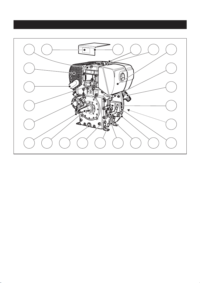
2. Description of the engine
5
Fig. 1
1 Type plate
2 Cylinder head cover
3 Exhaust silencer
4 Exhaust mesh insert
5 Oil pressure switch
6 Starter motor
7 Voltage regulator
8 Crankshaft - power take-off
9 Oil drain plug
10 Speed adjustment lever
11 Oil filter
12 Engine mountings
13 Ignition key
14 LED display
15 Intake opening for cooling and
combustion air
16 Oil filler pipe and dipstick
17 Recoil starter
18 Engine shutdown pin
19 Dry-type air cleaner
20 Lifting lug (see also Fig 32, Pos. 1)
21 Fuel tank cap
22 Noise insulating hood
12
3
4
5
6
7
8910
2122
9
11
12
20
13
19
18
17
16
15
14
Page 7

3. General notes
3.1. Technical data
Type 1B20 1B30 1B40
Design Air-cooled four-stroke diesel engine
Combustion system Direct injection
Number of cylinders 1 1 1
Bore / stroke mm 69 / 62 80 / 69 88 / 76
Displacement cm
3
232 347 462
Lubricating oil capacity l, approx. 0.9* 1.1* 1.5*
Difference between
“max” and “min” levels l, approx. 0.5* 0.5* 0.8*
Lubricating oil consumption
(after running in) approx. 0.5 % of fuel consumption at full load
Lubricating oil pressure
(oil temperature 100 °C) approx. 2.5 bars at 3000 r.p.m.
Direction of rotation,
power take-off end anti-clockwise
Valve clearance 10 - 30 °C
Inlet and exhaust valve mm 0.10
Max. tilt angle in operation, Flywheel 25° down
in direction all other directions 35°
Weight (incl. fuel tank, air-cleaner,
exhaust silencer, recoil starter and kg,
electric starter) approx. 33 38 55
Battery capacity Amp/h max. 12 V / 60 Amp/h
* These values are intended as an approximate guide. The max. marking on the dipstick is the
determining factor, Fig. 7.
Tightening torques
Item Nm
Oil drain plug 50
6
Page 8

3.2. Transport
Standard lifting lug „20“ is to allow
the engine and its auxiliaries to be
transported safely, chap. 2. It is not suitable or
approved for lifting the complete equipment to
which the engine is attached.
3.3. Notes on installation
The „Guide to selecting and installing an engine“
contains all the necessary information on engine
applications if you have an engine which has not
yet been installed in equipment and still has to
be fitted or set up.
This guide is available from your local
HATZ service station.
Do not exceed the forces and torques
indicated on the speed adjustment
lever and the stop pin, otherwise you may
damage the stops and internal governor components. Figure 2.
3.4. Load on engine
Operating the engine for a lengthy period offload or at very low loads can affect its running
quality.
We therefore recommend a minimum engine
load of 15 %. If operated at such low loads, it is
best to operate the engine at a significantly higher load for a short period before switching it off.
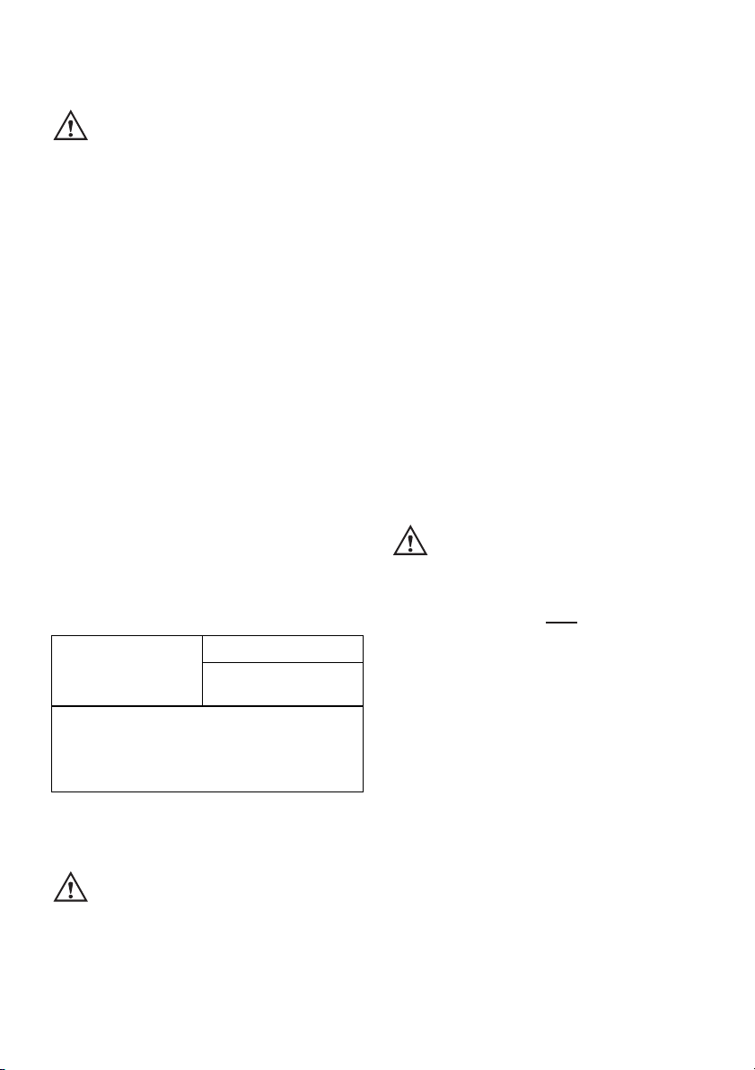
3.5. Type plate
The type plate is placed on the noise insulating
hood (Fig. 1, pos. 1) and includes the following
engine information (Fig. 3):
➀ engine type
➁ code (only for special equipment)
➂ engine number (also stamped on crankcase,
Fig. 4)
➃ max. engine speed
For any offer as well as spare parts orders it is
necessary to mention these data (also see spare
parts list, page 1).
4. Operation
4.1. Before starting up for the first time
Engines are normally supplied dry, i.e. not containing fuel or oil.
4.1.1. Engine oil
Oil quality
CCMC- D4 - D5 - PD2 or
API - CD - CE - CF - CG or
SHPD
If engine oil of a poorer quality is used, reduce
oil change intervals to 150 hours of operation.
Oil viscosity
Select the viscosity class according to the
ambient temperature for cold starts (Fig. 5).
When adding oil or checking the oil level, the
engine must be horizontal.
– Remove oil filler screw and add engine oil,
Fig. 6.
Lubricating oil capacity: see Chapter 3.1.
– To check the oil level, remove the dipstick,
clean it - then screw it back in and finally
remove it again, Fig. 7.
Check the oil level on the dipstick and, if
necessary, top up to the max. level.
4.1.2. Version with oilbath air cleaner
– Take off oil reservoir „1“ and fill with engine oil
as far as the mark, Figs. 8 and 9.
– Insert the filter element into the oil reservoir
with the long end „2“ leading, Fig. 8.
– Attach the oil reservoir, making sure that
sealing ring „3“ is correctly seated and
fasteners „4“ are tight.
7
Page 9
4.1.3. Fuel
Stop the engine before refilling the
fuel tank. Never refuel near a naked
flame or sparks which could start a fire. Don't
smoke. Use only pure fuel and clean filling
equipment. Take care not to spill fuel.
All diesel oils which satisfy the following specifications are suitable:
EN 590 or
DIN 51601 - DK or
BS 2869 A1 / A2 or
ASTM D 975 - 1D / 2D
– Remove fuel tank cap, Fig. 10.
– Fill the fuel tank at least half full with diesel oil,
Fig. 11.
The fuel system does not require to be bled
as this is done automatically.
– Replace fuel tank cap, Fig. 12.
At temperatures below 0 °C, winter-grade fuel
should be used or paraffin added to the fuel well
in advance.
4.2. Starting
Do not run the engine in closed or
badly ventilated rooms – danger of
poisoning! Before starting the engine, ensure
that no-one is in the danger area close to the
engine or equipment, and that all protective
guards are fitted.
4.2.1. Starting procedure
If possible, disengage the engine from any
driven equipment.
The auxiliary equipment should always be placed
in neutral.
– First of all set the speed adjuster to the STOP
position, Figures 13 and 14, then move it to
the starting position.
Speed adjuster, standard version
– Set speed adjustment lever „1“ either to 1/2
START or max. START position, as desired or
necessary (Fig. 13).
Starting at a lower speed will help to prevent
exhaust smoke.
Speed adjuster with pull rod
– Move speed adjuster to the „START/RUN“
position, Figure 14.
Never use starting sprays!
Fig. 15.
4.2.2. Recoil starter with decompression
device (down to –6 °C)
– Starting procedure, see Chapter 4.2.1
The engine has an automatic decompression
system, which allows for a start from any position. However, we would like to recommend the
following procedure:
– Pull the starting cable out by the handle until
you feel a slight resistance, Fig. 16.
– Let the cable run back; in this way the entire
length of the starting cable can be used to
start the engine.
– Devices which are not securely fastened
should be restrained with the foot.
– Grip the handle with both hands, Fig. 17.
8
Lowest ambient
temperature when
starting, in °C
0 up to –10 20 % –
–10 up to –15 30 % –
–15 up to –20 50 % 20 %
–20 up to –30 – 50 %
Paraffin content for:
Summer Winter
fuel fuel
Page 10

– Commence pulling the starting cable vigorous-
ly and at an increasing speed (do not jerk it
violently) until the engine starts, Fig. 18.
On engines with an electric start system the
recoil starter also acts as an emergency-starter.
In this case the automatic decompression
system will switch back to normal compression
at a very low speed.
For this reason, please note that the starting
procedure described previously must be
followed exactly.
Note:
If after several attempts of starting the exhaust
begins to emit white smoke, move the speed adjustment lever to the STOP position and pull the
starting cable out slowly 5 times.
Repeat the starting procedure, Chapter 4.2.1.
4.2.3. Recoil starter without decom-
pression device (special version)
For use in regions with ambient temperatures of
–18 °C or lower, the engines are supplied without a decompression device.
At such low temperatures, only the electric
starter should be used.
The recoil starter serves as an emergency
starting device at higher temperatures (–6°C or
above).
– Prepare the engine for starting;
see Chapter 4.2.1.
– Pull out the handle with the cord slowly until
compression resistance is clearly felt; Fig. 16.
– Continue to pull slowly but with greater force
until the resistance becomes noticeably less
(compression overcome).
– Now let the cord run back - the engine is in
the correct starting position.
In this way the engine can be accelerated
through about one and a half revolutions with
the starting cord, to overcome compression resistance and achieved the required momentum
for starting.
– Support equipment with the foot if it is too
light in weight or liable to tip over.
– Take hold of the handle with both hands;
Fig. 17.
– Pull the starting cord up forcefully and at an
increasing speed (but do not jerk it) - the engine should then start.
4.2.4. Electric starter
– For starting preparations, see Chapter 4.2.1.
– Insert the key and turn it to position I, Fig. 19
and Fig. 20.
Depending upon the model, the battery charge
telltale „2“ and the oil pressure warning light „3“
will come on.
– The engine temperature display „4“ (additional
equipment) lights up if the temperature at the
cylinder head becomes too high.
Switch off the engine and trace and eliminate the cause of the problem, see chapter 6.
– Turn the key to position II.
– Release the key as soon as the engine runs.
The starting key must spring back to position I
and remain there during engine operation.
– The battery charge and oil pressure lights
should extinguish directly after the engine
starts. The display lamp „1“ lights up to show
that the engine is running.
– Prior to starting up again, the key has to be
returned to position 0. When the engine is
running the starter repeat lock in the ignition
switch will prevent the starter from engaging
and suffering damage.
9
Page 11

Preheater system (optional extra)
When starting a cold engine, the preheat indicator „5“ will light, Fig. 19 and Fig. 20.
– Start the engine immediately after the light
goes out.
Fuel shut-off valve, stop solenoid
(additional equipment)
As soon as the starting key is at Position I, fuel
shut-off valve „1“ is electrically released; Fig. 21.
The fuel feed to the injection pump is then open
and the engine is ready to start.
When the engine is running, turning the starting
key to position 0 closes the cut-off valve and interrupts the fuel supply to the injection pump, so
that the engine stops; Chapter 4.3.
This shut-off valve is also used for the automatic
electrical shutdown system.
Emergency start
If the shut-off valve is blocking the fuel supply
as a result of an electrical fault and the engine
therefore cannot be started, an emergency start
can be attempted.
Proceed as follows for this:
– Turn the emergency start lever „1“ approx.
180° counter-clockwise as far as its stop,
using suitable pliers (the lead seal wire will
break off); Fig. 22.
– As soon as the emergency start lever is in the
starting position, the electric starter or recoil
starter can be used; Chapter 4.2.2 and 4.2.3.
The oil level must always be checked before an
emergency start, as insufficient oil pressure
can lead to complete damage of the engine
within a very short time.
After this, the engine can only be
stopped with the starting key in the
emergency operating mode if the emergency
starting lever is first turned back clockwise to
the stop position.
Immediately after a period of emergency running, ascertain the cause of the fault and have it
rectified; Chapter 6.
Have the emergency-starting lever sealed once
again by a HATZ service point.
When the automatic electrical shutdown system
is used, the emergency start described above
means that liability for risks must be accepted
by the operator (not covered by our warranty!)
In case of difficulty contact the nearest HATZ
service point.
Automatic electrical shutdown system
(additional equipment)
Engines with the automatic shutdown system
can be recognised by the externally located instrument box with preheat indicator „5“, Fig. 20.
Important!
If the engine cuts out immediately after starting
or switches off by itself during operation, a
monitoring element in the automatic shutdown
system has tripped. The corresponding indicator
light (Fig. 20, positions 2 - 4) will come on.
After the engine has stopped, the display continues to glow for about 12 seconds.
The electrical device then switches itself off automatically.
The display lights up again after the start key
has been turned back to position 0 and then to
position I again.
Trace and eliminate the cause of the operating
fault before trying to restart the engine
(see chapter 6).
The display light goes out when the engine is
next started.
Even with automatic shutdown monitoring the
oil level must be checked every 8 – 15 operating hours (Chapter 5.2.1.).
10
Page 12

4.3. Stopping the engine
Speed adjuster, standard version
– Move the speed adjustment lever „1“ back
to the STOP position. The engine cuts out,
Fig. 13.
Note:
Engines with a fixed lower idling speed cannot
be switched off using the speed adjustment
lever. See the paragraph entitled „Other ways of
switching off the engine“.
Speed adjuster with pull rod
(optional extra)
– Move the speed adjuster to the „STOP“ posi-
tion and press it until the engine cuts out,
Fig. 14.
Other ways of switching off the engine
1. Fuel shut-off valve, stop solenoid
(optional extra)
– Turn ignition key to the 0 position. The engine
cuts out, Fig. 19 and Fig. 20.
2. Stop pin (optional extra)
– Press the stop pin „2“ until the engine cuts
out, Fig. 13.
– Once the engine has cut out, release the
pin „2“ and ensure that it returns to its initial
position.
Depending upon the model, the battery charge
indicator „2” and oil pressure warning indicator
„3“ will come on again after the engine comes to
a stop, Fig. 19 and Fig. 20.
– Turn the key to position 0 and remove it.
All the indicator lights must go out, Fig. 19
and Fig. 20.
Note:
Failure to return the starter key to position 0
may result in the battery being totally
discharged.
If operation of the engine is inter-
rupted for any reason, or at the end of
the working day, the starter key should be kept
out of reach of unauthorised persons.
11
Page 13

5. Maintenance
Only carry out maintenance work with the engine switched off.
Observe all relevant laws and regulations governing the handling and disposal of used
oil, filters and cleaning agents.
Protect the starting key against unauthorised use.
On engines with an electric starter, disconnect the battery's negative terminal.
When maintenance work has been completed, check that all tools have been removed from
theengine and all protective guards fitted again.
Before starting the engine, ensure that there are no persons in the danger area close to the
engine or equipment.
5.1. Maintenance chart
12
Maintenance interval Maintenance work required
Chap.
Every 8 – 15 operating
hours, or before each
daily start-up
Check oil level.
Examine the lower section of the oilbath air
cleaner to ensure correct oil level and freedom
from contamination; change the oil if it contains
sludge.
On version with cyclone-type dust trap, empty the
dust collector.
Check combustion and cooling air intake zone.
Check air-cleaner maintenance indicator.
Check the water trap.
5.2.1.
4.1.2.
5.3.1.
5.3.1.
5.2.2.
5.2.3.
5.2.4.
Every 250
operating hours
Oilbath air cleaner maintenance.
Change engine oil.
Check and adjust valve clearances.
Clean cooling air area.
Check screw connections.
Clean mesh insert for exhaust.
5.3.1.
5.3.2.
5.3.3.
5.3.4.
5.3.5.
5.3.6.
Every 500
operating hours
Change fuel filter element.
Dry-type air cleaner maintenance.
5.4.1.
5.4.2.
Every 1000
operating hours
Clean the oil filter. 5.5.1.
8-15
250
500
1000
Page 14

The above maintenance chart is supplied with
every engine. This label should be affixed to the
engine or equipment in an easily visible position.
The maintenance chart governs the maintenance
intervals.
On new or reconditioned engines, after the
first 25 operating hours, always
– Change engine oil, Chapter 5.3.2.
–
Check valve clearances and adjust if necessary,
Chapter 5.3.3.
– Check screw connections for tightness,
Chapter 5.3.5.
If the engine is not used frequently, change the
engine oil after 12 months at the latest, regardless of the actual number of hours it has been in
operation.
13
8-15
250
IN 0.1 mm
0.004 "
EX 0.1 mm
0.004 "
°C°F
OIL: SAE...
122
4050104
30
86
20
68
5W/40
10
50
5W/30
10W / 3 0
0
32
10W
-10
14
-20
-4
-30
-22
-40
-40
OIL
OIL
40
30
15W / 4 0
10W / 4 0
500
1000
051 104 02
1B20
Page 15

5.2. Maintenance every 8 - 15
operating hours
5.2.1. Checking engine oil level
To check the oil level, the engine must be
standing level and be switched off.
– Remove any dirt from the oil dipstick area.
– Remove dipstick and clean it.
– To check the oil, screw the dipstick back in
and then remove it again, Fig. 7.
– Check the dipstick oil level and, if necessary,
add oil to the max. mark, Chapter 4.1.1.
5.2.2 Check air intake area for
combustion and cooling
Heavy contamination is an indication that increased dust accumulation necessitates a correspondingly shorter maintenance interval,
Chapter 5.3.1., 5.3.4. and 5.4.2.
– Check air intake points for severe blockage
due to leaves, heavy dust accumulation etc.,
and if necessary clean them, Fig. 23.
On version with oilbath air cleaner, also check
air intake area „2“, Fig. 28.
5.2.3. Check air cleaner maintenance
indicator (optional extra)
Mechanical service indicator
– Increase the speed of the engine briefly to the
maximum.
If the rubber bellows shrinks and covers the
green area „1“, the air cleaner system should
be serviced, Figure 24, Chapter 5.4.2.
Under dusty conditions, check the rubber bellows several times per day.
5.2.4. Checking the water trap
The intervals at which you should check the
water trap depend entirely on the amount of
water in the fuel and the care taken when refuelling. The normal interval is once a week.
– Loosen hexagon screw „1“ with approx.
3-4 rotations; Fig. 25.
– Trap the drops which emerge in a transparent
vessel. Since water has a greater specific gravity than diesel fuel, the water emerges before
the diesel fuel. The two substances separate at
a clearly visible line.
– As soon as diesel only emerges at screw „1“,
this can be tightened again.
If an external water trap is attached, check its
water content every day, when the engine oil
level is checked. The water which has collected
is separated at a clearly visible line from the
diesel fuel above it.
– Open drain plug „1“ and drain the water out
into a suitable vessel; Fig. 26.
– If the drain plug is difficult to reach, an exten-
sion hose can be attached to it.
14
Page 16

5.3. Maintenance every 250
operating hours
5.3.1. Oilbath air cleaner maintenance
– Take off oil reservoir „1“ and clean it, Fig. 27.
– Rinse out filter element „2“ in diesel oil; allow
it to drip thoroughly and wipe it down before
re-assembling the air cleaner.
– If severely contaminated, clean filter
housing „3“.
Never attempt to repair the oilbath air cleaner by
welding, brazing etc., as this could damage the
filter beyond repair and cause engine damage.
– Re-attach parts previously removed from the
air cleaner and add oil so that it is ready for
use, Chapter 4.1.2.
Version with cyclone-type dust trap
– Take off dust collector „1“, empty it and
wipe clean (dust collector must remain dry),
Fig. 28.
– Clean intake aperture „2“ (also keeping it dry).
Important:
Do not add any oil to the dust collector.
– Attach the cyclone-type dust trap and secure
with the wing nut.
5.3.2. Changing engine oil
The engine must be standing level and be
switched off.
Only change the oil when the engine is warm.
Danger of scalding from hot oil!
Trap the old oil and dispose of it in
accordance with local legislation.
– Take out oil drain plug „1“ and allow the oil to
drain out, Fig. 29.
– Clean the oil drain plug „1“, fit a new washer
„2“,
insert and tighten.
Tightening torque: 50 Nm.
– Add engine oil, Chapter 4.1.1.
5.3.3. Checking and adjusting valve
clearances
Only carry out adjustments when the engine is
cold (10 - 30 °C).
– Remove air cleaner cover, fig. 30 and noise-
insulating hood, Fig. 31.
– On version with oilbath air cleaner, remove
screw „2“ and take off cover plate with noiseinsulating hood, Fig. 32.
– Remove any contamination adhering to the
cover for the cylinder head.
– Remove screws „1“ (two screws on 1B20 and
1B30 engines, three screws on 1B40 engines)
and take off the cylinder head cover with gasket „2“, Fig. 33.
– Remove rubber cap from the inspection hole
cover, Fig. 34.
– Turn the engine over in the normal direction of
rotation until the valves are in the overlap position (exhaust valve not yet closed, inlet valve
starts to open).
– Turn the crankshaft through 360° in the
normal direction of rotation and align exactly
to the • • •-marking, Figure 34.
– Check valve clearances with feeler gauge „1“
(0.10 mm), Fig. 35.
– If valve clearances require adjusting, slacken
off screw „2“ and turn hex nut „3“ until feeler
gauge „1“ can be pulled through with just
slight resistance when screw „2“ is retightened.
– Fit cover for cylinder head and tighten evenly,
always using a new gasket.
15
Page 17

– Re-attach parts previously removed from
engine.
Do not forget: replace the rubber cap at the
inspection hole cover.
– Carry out a brief test run, then check the cover
for leaks.
5.3.4. Cleaning the air cleaner zone
The engine must be switched off and
cooled down before cleaning!
– If severely contaminated, clean the cooling fins
on the cylinder and cylinder head, and also the
fan blades in the flywheel. If necessary, contact your local HATZ service station.
5.3.5. Checking screw connections
– Check the engine mounting screws for tight-
ness.
The adjusting screws at the engine
governor and on the injection system
are sealed with lacquer and are not to be tightened or adjusted, Fig. 36.
5.3.6. Cleaning the exhaust mesh inlet
Exhaust system components will natu-
rally be hot and must not be touched
while the engine is running or until it has
cooled down after being stopped.
– Unscrew hex nut and remove the exhaust
mesh insert, Fig. 37.
– Remove any deposits in the mesh insert by
means of a wire brush.
– Check the exhaust mesh insert for cracks or
damage and, if necessary replace with a new
one.
– Screw on hexagon nut „1“ by approx. 1 turn,
Fig. 38.
– Insert exhaust screen with hoop „1“ into hole,
them pull outwards again so that the hoop is
retained, Fig. 39.
– Tighten the hexagon nut fully.
16
Page 18

5.4. Maintenance every 500
operating hours
5.4.1. Renewing fuel filter
The maintenance intervals for the fuel filter are
dependent upon the purity of the diesel oil being
used and, if necessary, may have to be reduced
to 250 hours.
When working on the fuel system, do
not expose it to naked flames; do not
smoke.
Important:
Keep the entire area clean so that no dirt
reaches the fuel.
Model with fuel filter in fuel tank
– Open the tank cover and pull the fuel filter out
of the tank by its cord; Fig. 40.
– Pull fuel supply line „1“ off fuel filter „2“ and
insert a new filter, Fig. 41.
– Fit the fuel filter again and close the tank cap.
Bleeding of the fuel injection system takes
place automatically.
Model with external fuel filter
– Empty the fuel tank by taking out screw „1“,
Fig. 25 or Fig. 26 and allow the fuel to drain
into a clean vessel. This fuel can be re-used
later.
– Unscrew the fuel filter from its mount, Fig. 42.
– Place a suitable vessel under the filter to trap
the residual fuel.
– Pull off fuel supply line „1“ at both ends of fuel
filter „2“ and insert the new filter, Fig. 43.
– Always renew the fuel filter. Note the arrows
indicating the correct direction of flow.
– Secure the filter to its mount.
– Fill the fuel tank with diesel oil; Chapter 4.1.3.
Air is vented from the fuel system automatically.
– Check the fuel filter and lines for leaks after a
short test run.
5.4.2. Air cleaner maintenance
The filter cartridge should only be cleaned when
the maintenance lamp lights at maximum speed,
Chap. 5.2.3.
However, the filter cartridge should always be replaced after 500 operating hours at the latest.
– Remove the air cleaner cover, Fig. 30.
– Unscrew and remove knurled nut „1“ and take
off air cleaner element „2“, Fig. 44.
– Clean the filter compartment and the cover.
Dirt and other foreign bodies must not be
allowed to enter the engine’s air inlet points.
– On versions with a mechanical air cleaner
service indicator, check the condition and
cleanliness of valve plate „1“, Figure 45.
– The filter cartridge should either be renewed
or, depending upon the degree of contamination, cleaned, or checked, as follows:
Cleaning the filter cartridge
Dry contamination
Use compressed air to blow through the filter
cartridge from the inside outwards, until no further dirt emerges, Fig. 46.
Important!
The pressure must not exceed 5 bar.
Moist or oily contamination
Renew the filter cartridge.
17
Page 19

Checking the filter cartridge
– Check filter cartridge's gasket surface „1“ for
damage, Fig. 46.
– Check the filter cartridge for cracks or any
other type of damage to the paper filter by
holding it inclined towards the light or by
shining a light source through it.
Important!
The slightest damage to the paper filter rules
out it being used any longer.
– Re-assemble the filter cartridge in the reverse
order of work.
5.5. Maintenance every 1000
operating hours
5.5.1. Cleaning the oil filter
The oil filter should be cleaned at the same time
as the engine oil is changed, since oil escapes
when the filter is removed.
The engine must be standing horizontally and
switched off.
Danger of scalding from hot oil!
Trap the old oil and dispose of it in
accordance with local legislation.
– Loosen screw „1“ with approx. 5 rotations,
Fig. 47.
– Remove oil filter from housing, Fig. 48.
– Use an air line to blow out oil filter dirt from
the inside outwards, Fig. 49.
– Check joint washer „1“ whether it is damage;
replacement if necessary, Fig. 50.
– Check joint washer „2“ whether it is damage
and correctly fitted, replace oil filter if neces-
sary.
– Lubricate joint washer before fitting.
– Put in oil filter and press until limit stop,
Fig. 51.
– Check whether tension springs sit close to oil
filter with both ends „1“, before tightening
screw.
– Check the oil level and restore to the max.
level if required, Chapter 4.1.1.
18
Page 20

6. Malfunctions – causes and remedies
Malfunctions Possible causes Remedy Chap.
19
6.1.
Engine does not
start, or not immediately, but can be
turned over easily
as usual.
At low
temperatures.
Speed control lever in stop or
idle position.
Engine shutdown pin in STOP
position.
No fuel in the injection pump.
Insufficient compression:
-Incorrect valve clearance.
-Valves worn.
-Cylinders and/or piston rings
worn.
Injector not functioning.
Below starting threshold
temperature.
Equipment not disengaged.
Preheating system faulty
(optional extra).
Fuel has inadequate resistance
to low temperatures.
Move lever to START position.
Move to operating position by
pulling the pin gently.
Add fuel.
Systematically check the entire
fuel supply system:
If still no fault found,
-check engine feed line
-check fuel filter
Check valve clearances, adjust if
necessary.
See workshop manual.
See workshop manual.
See workshop manual.
Operate preheater
(optional extra).
Disengage engine from equipment, if possible.
See workshop manual.
Check whether clear (not turbid)
fuel emerges at the fuel line detached from the injection pump.
If turbid or separated - either
warm up the engine or drain the
complete fuel supply system.
Refill with winter-grade fuel to
which paraffin has been added.
4.2.1.
4.3.
4.1.3.
5.4.1.
5.3.3.
4.2.4.
4.1.3.
Page 21

Malfunctions Possible causes Remedy Chap.
20
At low
temperatures:
If equipped with a
stop solenoid or
automatic electrical shutdown system (additional
equipment)
6.2.
Engine fires but
does not run.
Automatic
electrical shut-off
device
(optional extra)
6.3.
Starter motor does
not operate or engine does not turn
over.
Starting speed below 400 min
-1
-Viscosity of oil too high.
-Battery charge too low.
Solenoid faulty and/or fault in
the electrical system.
Speed control lever not moved
far enough towards „START“.
Equipment not disengaged.
Fuel filter blocked.
One of the automatic shutdown's monitoring elements
has initiated a stop signal.
(See also Chapter 6.4.)
Fault in the electrical system:
-Battery and/or other cables
incorrectly connected up.
-Cable connections loose and/or
oxidised.
-Battery faulty and/or flat.
-Starter motor faulty.
-Faulty relays, monitoring
element.
Change lubricating oil and add
oil of the correct viscosity class.
Check the battery, if necessary
contact a service station.
See workshop manual.
Move lever to „START“ position.
Disengage engine from equipment if possible.
Renew fuel filter.
Localise the monitoring element
responsible and clear the fault,
or contact a
HATZ service station.
Check electrical system and its
component. See also the workshop manual.
5.3.2.
4.1.1.
7.
4.2.1.
5.4.1.
7.
Page 22

Malfunctions Possible causes Remedy Chap.
21
Fuel supply interrupted
-Tank has run empty.
-Fuel filter blocked.
-Tank venting inadequate.
Mechanical faults.
One of the automatic shutdown's
monitoring elements has initiated a stop signal.
Monitoring element for:
-oil pressure too low
-engine temperature too high
-defective alternator.
Fuel supply interrupted:
-Tank has run empty.
-Fuel filter blocked.
-Tank breathing inadequate.
-Speed control lever does not
remain in desired position.
Air cleaner contaminated.
Valve clearances incorrect.
Injector not functioning.
Add fuel.
Change fuel filter.
Ensure adequte tank venting.
Contact a HATZ service station.
Localise the monitoring element
responsible and clear the fault,
or contact a
HATZ service station.
Check oil lubrication.
Check air cooling zone for contamination.
See workshop manual.
Add fuel.
Change fuel filter.
Provide adequate tank breathing.
Lock the lever into position.
Clean or renew the air cleaner.
Adjust valve clearances.
See workshop manual.
4.1.3.
5.4.1.
5.2.1.
5.3.4.
4.1.3.
5.4.1.
5.3.1.
5.4.2.
5.3.3.
6.4.
Engine cuts out of
its own accord
during operation.
Automatic
electrical shut-off
device
(optional extra)
6.5.
Engine output and
speed both drop.
6.6.
Engine output and
speed fall, black
smoke from exhaust.
Page 23

Malfunctions Possible causes Remedy Chap.
22
6.7.
Engine becomes
very hot. Indicator
lamp for cylinder
temperature
(optional extra)
comes on.
6.8.
Moisture condensate emerging
from exhaust.
Too much lubricating oil
in engine.
Inadequate cooling:
-Contamination of entire
cooling air zone.
-Air duct panels not
properly sealed.
Operation off load for a prolonged period.
Drain off lubricating oil as far as
upper mark on dipstick.
Clean cooling air zone.
Check cooling air deflector
plates and shafts for completeness and airtight seal.
Operate the machine at about
70 % load until moisture no
longer emerges from the exhaust.
5.3.2.
5.3.4.
Page 24

7. Work on the electrical
system
Batteries generate explosive gases.
Keep them away from naked flame and
sparks which could cause them to ignite.
Do not smoke.
Protect eyes, skin and cloth against the corrosive battery acid. Pour clear water over acid
splashes immediately. In case of emergency
call doctor.
Do not place any tools on top of the battery.
– Do not confuse the positive (+) and
negative (–) terminals of the battery.
– When fitting the battery, first connect up the
positive lead, then the negative lead.
Negative terminal to earth = engine block.
– When removing, first disconnect the negative
lead, then the positive lead.
– Always take care to avoid short-circuits and
earth (ground) contact of live cables.
– If malfunctions occur, first of all check that
cable connections make good contact.
– Replace a failed indicator light without delay.
– Do not remove the ignition key while the en-
gine is running.
– Do not disconnect the battery while the en-
gine is running.
– Do not spray water on to components of the
electrical system when cleaning the engine.
If this is unavoidable, disconnect the battery
first and carefully blow all components dry
before reconnecting.
– When carrying out welding work on the en-
gine or equipment, fit the earth clip of the
welding equipment as close to the welding
point as possible and disconnect the battery.
The connecting plug for the voltage regulator
must be removed.
The relevant circuit diagrams are enclosed with
the engine if it is equipped with an electrical system. Additional circuit diagrams can be supplied
to order.
Electrical systems that do not comply with HATZ
circuit diagrams are excluded from warranty.
8. Storage out of use
The new engine can normally be stored dry for
up to one year.
In very humid climates or coastal regions, the
protective treatment is sufficient for up to about
6 months.
For longer periods of storage, please contact
your nearest HATZ service station.
9. Warranty
Not applicable for the U.S.A. and Australia.
The right to claim under guarantee lasts for a
period of 12 up to 24 months (according to the
equipment) or for a maximum of 2000 working
hours, depending which criteria are met first.
Warranty is granted according to the terms stated in our warranty agreements, details of which
are available from every HATZ service station.
23
Page 25

F<15 N STOP
2
GMBH
CO
+
3
6
7
4
5
MOTORENFABRIK HATZ KG
D-94099 RUHSTORF
TYP
MOTOR/ FABRIK NO.
KENNZ.
ABE/AUSF.
GMBH
+
CO
<
F 30 N
<
M 2.3 Nm
-1
MIN NH PV CM
3
76.5°
STOP
START
MADE IN GERMANY
°C°F
OIL: SAE...
50
122
40
104
30
86
20
68
10
50
0
32
-10
14
-20
-4
-30
-22
-40
-40
5W/40
5W/30
15W/40
10W/40
10W/30
10 W
30
40
2438 / 1
max.
Page 26

2440 / 10
8
9
12 13
10
11
2444 / 5
2439 / 12
2439 / 16
2439 / 9
Page 27

14
050 145 00
15
18 19
16
17
2438 / 17
2441 / 3
2444 / 17
Page 28

1
20 21
24
25
22
23
2
3
4
5
2438 / 12
1
1
Page 29

26
27
30 31
28
29
1
2444 / 3
2440 / 13
2443 / 12
2445 / 3
Page 30

2442 / 18
32
33
36
37
34
35
2
1
23
1
2
3
2119 / 3
2442 / 6
Page 31

2441 / 12
38 39
42 43
40
41
2441 / 8
Page 32

2442 / 3
44
45
48
49
46 47
2444 / 10
1
2445 / 10
Page 33

50 51
Page 34

CALIFORNIA
Proposition 65 Warning
Diesel engine exhaust and some of its
constituents are known to the State
of California to cause cancer, birth
defects, and other reproductive harm.
 Loading...